Article

Porous Cores in Small Thermoacoustic Devices for Building Applications

by
Fabio Auriemma
1,*,
Elio Di Giulio
2,
Marialuisa Napolitano
2 and
Raffaele Dragonetti
2
1
Department of Mechanical and Industrial Engineering, Tallinn University of Technology—TalTech, 19086 Tallinn, Estonia
2
Department of Industrial Engineering, University of Naples Federico II, 80125 Naples, Italy
*
Author to whom correspondence should be addressed.
Energies 2020, 13(11), 2941; https://doi.org/10.3390/en13112941
Submission received: 5 May 2020 / Revised: 29 May 2020 / Accepted: 2 June 2020 / Published: 8 June 2020
(This article belongs to the Special Issue Applied Thermodynamics and Heat Transfer for Buildings)

Abstract

:
The thermoacoustic behavior of different typologies of porous cores is studied in this paper with the goal of finding the most suitable solution for small thermoacoustic devices, including solar driven air coolers and generators, which can be used in future buildings. Cores provided with circular pores, with rectangular slits and with arrays of parallel cylindrical pins are investigated. For the type of applications in focus, the main design constraints are represented by the reduced amount of the input heat power and the size limitations of the device. In this paper, a numerical procedure has been implemented to assess the behavior of the different core typologies. For a fixed input heat power, the maximum acoustic power delivered by each core is computed and the corresponding engine configuration (length of the resonator and position of the core) is provided. It has been found that cores with parallel pins provide the largest amount of acoustic power with the smallest resonator length. This conclusion has been confirmed by experiments where additive manufactured cores have been tested in a small, light-driven, thermoacoustic prime mover.

Graphical Abstract

1. Introduction

This paper addresses the main technical problems involved with the use of small thermoacoustic heat engines—prime movers and heat pumps—in building applications. Different destinations in future buildings, including net zero-energy buildings [1], can be foreseen for thermoacoustic devices, especially solar driven air coolers and electric generators with small input powers [2,3]. In case of coolers, two heat engines are required: the first one is a prime mover which uses heat from solar radiation to generate acoustic power; the second one is a heat pump which uses the acoustic power to subtract heat from surrounding air [4]. For electric energy generation, a linear generator, a reversed loudspeaker or a piezoelectric device can be combined with the prime mover to perform the acoustic-to-electric power conversion [5,6]. This kind of solutions can help reducing the total emissions of future buildings.
Thermoacoustic heat engines (TAHE) exploit the thermal diffusion process occurring in internal porous cores in order to pump mechanical energy into the working fluid or to extract heat from it [7]. These cores act as thermal reservoirs, providing heat exchanges between the solid surface of the pores and the oscillating fluid. Heat exchanges take place within the thermal boundary layer (δk), which has sub-millimeter thickness and requires a similar order magnitude of the pore size. However, the thickness of the viscous boundary layer (δv) has also same order magnitude as the pore size. As a consequence, large viscous losses take place in the fluid within the porous core. This condition, typically utilized in sound absorptive elements, is undesired in thermoacoustic devices which, inevitably, suffer from substantial viscous losses [8,9].
Thermoacoustic heat engines can be categorized into two groups, standing-wave and travelling-wave, according to the phase difference—nearly π/2 and nearly zero, respectively—between sound pressure and particle velocity. In other words, the first heat engine typology requires porous cores with Sh = O(1), whilst travelling-wave devices require Sh = O(−1), being Sh = d/2δv the Shear wavenumber and d is the characteristic dimension of the pores.
Only standing-wave devices are studied in this paper, for which the porous core is equivalently referred to as “stack”.
By looking at the pore shape, an unlimited number of stack typologies can be found and studied. Practical solutions include mainly slit shaped pores, circular, triangular, honeycomb shapes and pin arrays. Fundamental studies in thermoacoustics, conducted by Rott [10] and Arnott et al. [11] on circular, square, rectangular and triangular pores point out that parallel sided pores exhibit better performance than other hollow pore geometries. The use of laminae in spiral configurations is one way to build cores with approximately parallel sided pores [7,12]. Semi-phenomenological models for porous materials have been used to study the thermoacoustic behavior of different cores in [13,14].
In another fundamental study [15], Swift et al. theoretically showed that cores with convex pores geometries, e.g., longitudinal pin array stacks, perform better than any hollow pore stack, including cores with parallel plates, due to the reduced amount of viscous losses when the working fluid has Prandtl number (Pr) < 1 (e.g., air). However, the approach used in [15] to assess the performance of pin cores is based on a figure of merit which is a rather qualitative approach, because neither the acoustic power generated nor the input heat power are accounted for. The literature related to pin array stacks is quite narrow because manufacturing issues have limited the use of this type of cores [15,16]. Among the main investigations, it is worth mentioning the studies related to cores with parallel pins, but displaced transversally to the fluid in order to reduce the heat transfer along the core [17,18].
Recently, the manufacturing issues of pin array cores have been largely overcome with the advent of additive manufacturing, as shown in the studies [19,20]. For this reason, the goal of this paper is to investigate additive manufactured cores with parallel pins and to provide a thorough comparison with traditional porous geometries. In this way, it is possible to detect which core typology is more suitable for building applications, where the input thermal power is limited and size constraints bind the length of the resonator. To this aim, the behavior of cores constituted by parallel pins, slits and circular tubes, but provided with equivalent thermo-viscous properties, has been modelled by means of one dimensional thermoacoustic simulations. An optimization procedure has been implemented where, per each core typology and for a given thermal input power, the resonator length and the position of the core which maximize the output power are found [21,22]. By comparison, it is possible to detect the best solution for the above mentioned thermoacoustic applications. It will be shown that cores made of circular tubes and slits greatly differ from cores which include parallel pins, providing less acoustic power and requiring longer resonator tubes. In a first approximation, the results provided here can be extended to more complex concave pore geometries, e.g., square and honeycomb pores, as well as to more complex convex pore arrangements, e.g., diamond pin cells and oblique pin cells. The numerical results are confirmed by an experimental comparison between different stacks in a light powered standing-wave prime mover.
This study will be followed by upcoming investigations on additive manufactured lattice cells with oblique or predominantly parallel pins, including optimization of the pore geometries and the use functionally graded materials [23,24].

2. Materials and Methods

2.1. Theoretical Background

2.1.1. Standing Wave TAHE

A schematic representation of a standing-wave TAHE prime mover is shown in Figure 1. The device consists of:
  • A resonator tube with diameter Dr and length Lr.
  • A porous core (stack) of length Ls located at a distance La from the rigid wall of the resonator.
  • A hot heat exchanger (HX) which heats up the first end of the stack, and a cold heat exchanger (CX) which cools down the second end of the stack.
  • Possibly, a utilizer. For instance, a thermoacoustic heat pump (i.e., reversed prime mover) for air cooling applications or a linear generator, a reversed loudspeaker, an impulse turbine or a piezoelectric device for electric energy conversion.
The presence of two microphones (M1, M2) and of two thermoacouples (TC1 and TC2) is envisaged in Figure 1 to monitor, respectively, the acoustic pressure at specific locations and the temperatures TH and TC at the hot and cold ends of the stack.
The core acts as a series of thermal reservoirs at different temperatures, due to the presence of the hot and cold heat exchangers and to the heat capacity of the core itself. At the frequency of the first—most unstable—acoustic mode of the resonator, the heat provided by the hot exchanger is delivered, through the stack, to the working fluid during the phase of greatest condensation. Similarly, the heat taken away by the cold exchanger is subtracted, through the stack, from the working fluid during the phase of greatest rarefaction. This condition, usually referred to as Rayleigh’s criterion, results in thermal-to-mechanical power conversion in the form of the amplification of sound waves at the expense of the heat provided. The acoustic emission takes place if the thermal gradient between the hot and cold end of the stack is greater than a critical value ΔTc.
In an open standing-wave thermoacoustic device, the resonator tube is basically a quarter-wave resonator and the operating frequency is c/4L, being c the speed of sound. Sound pressure gradient and particle velocity have ~π/2 phase shift and, in order to meet the Rayleigh’s criterion, imperfect heat transfer between the fluid and the porous material of the core is necessary. In fact, if the thermal contact was perfect, the phase shift would result in zero net heat transfer from any particular location of the stack to the fluid parcels, thus no net work would be converted. Imperfect thermal contact is realized by using stacks with a hydraulic radius of the pores which is roughly a few times larger than the thermal penetration length. Contrariwise, in travelling-wave thermoacoustic devices, where pressure and particle velocity are in phase, perfect thermal contact is required, therefore the hydraulic radius of the pores is similar to or smaller than the thermal penetration length.

2.1.2. Momentum and Thermal Diffusion

Thermal and viscous penetration depths are, respectively, defined as δ k = 2 k / ω and δ v = 2 μ / ω , where k is the thermal diffusivity of the medium and μ is the dynamic viscosity. δk and δv are the distances from the solid wall where heat and momentum can diffuse laterally during the time T/π, being T the period of the acoustic oscillation [25]. At longer distances, the fluid responds adiabatically to the acoustic perturbation. Instead, in proximity of the walls, the response is isothermal. At intermediate distances, a few times larger than δk, the response is somehow in between (imperfect thermal contact), which is the condition required by standing-wave thermoacoustic devices. δk and δv are linked by means of the Prandtl number of the fluid, P r = v / k = ( δ v / δ k ) 2 .
Viscous and thermal penetration depths are comparable lengths, which implies that thermoacoustic devices are affected by substantial viscous losses, especially in the porous core. However, in many fluids, Pr is less than one, which means that δv is smaller than δk, although the sizes remain comparable. For instance, Pr = 0.71 in air at 20 °C and slightly decreases up to 350 °C. This circumstance motivates the use of cores provided with convex—rather than concave—radii of curvature of the pores. In Figure 2, the thermal and momentum diffusion regions are schematized in the cross section of two different cores: one provided with convex pores (Figure 2a) and one with concave pores (Figure 2b). In both cases, the radii are supposedly identical and a fluid is chosen with Pr < 1, which means δv < δk. Since the momentum diffusion occurs in a region of fluid of thickness δv and the thermal diffusion in a region of thickness δk, the ratio Ak/Av between the thermal and viscous diffusion areas is higher in case of convex pores. As a consequence, for convex pores, the total volume involved in thermal diffusion, Vk, is sensibly larger than that involved in viscous losses, Vv. The circumstance represented in Figure 2a is the best-case scenario (pin array pores) for cores with convex surfaces, whilst the case in Figure 2b (circular tube pores) is the worst-case scenario for cores with concave surfaces. When the core is constituted by parallel plates, the pore surfaces are flat and concave at the vertexes, thus the amount of viscous losses reduces, but not as much as for pin cores.

2.1.3. Equivalent Cores

In order to compare the thermoacoustic performance of cores provided with different types of pores, the geometrical parameters must be chosen in order to have cores which are “equivalent” from the thermoacoustic point of view. A possible choice is enforcing the same hydraulic radius for the cores, conventionally defined as the ratio of the channel’s cross-sectional area to its perimeter, HR = A/Π [19]. More generally, the thermal characteristic length Λ can be used instead of HR. This parameter was first introduced by Champoux and Allard to study thermal effects inside porous material, following a primary work by Johnson et al. related to viscous effects [26,27]. The thermal characteristic length is defined as Λ = 2 V f l u i d / A w e t , where V f l u i d is the volume of fluid and A w e t is the wet area, namely the area of the solid skeleton of the core which is in touch with the fluid.
Imposing the same thermal characteristic length Λ for different cores represents the first condition to have equivalent cores, since the wet area is responsible for thermal diffusion and the volume of the fluid moving within the core is strictly linked to the viscous losses. Based on the definition of Λ , it is simple to obtain thermal characteristic length for circle, plate and pin geometries, as reported in Table 1.
However, the sole condition of equal Λ’ is not sufficient to completely define the geometries of the cores. By assuming that the manufacturing capabilities allow us to produce similar thicknesses for the solid parts of different cores, it is reasonable to impose a second condition to have equivalent cores, that is 2 r p = 2 h = 2 d . As a consequence, the distance between adjacent pins and the thickness of the solid skeleton (for slits and circular tubes) are also characterized. As shown in Table 1, these two geometrical parameters are related to the porosity of the core, ϕ = V f l u i d / V t o t a l , with V t o t a l being the total volume of the core.
Cores provided with parallel pins typically have pin arrays distributed in hexagonal or in square patterns. The first configuration was studied by Swift [15], while the second one has been used for the experiments in the present work, since it better fits the additive manufacturing process for the cores. Once the geometry of the cell with parallel pins in hexagonal array is fixed, imposing the same thermal characteristic length for pins in a square array results in equal radii of the equivalent dashed circles shown in Table 1: r1 = r0. Imposing the same diameters of the pins for the two patterns results in the same porosity but different pin spacing: y1 ≠ y0.
For infinitely long slits, imposing the same thermal characteristic length as for the pins in hexagonal array provides the distance 2a between plates. Furthermore, imposing 2 h = 2 r p results in the same porosity as for the pins.
For cores provided with circular tubes arranged in a hexagonal pattern, imposing thermal characteristic length equal to that of the pins in hexagonal array yields to radius R of the tubes equal to the characteristic length. The second condition which has been imposed, 2d = 2rp, does not provide the same porosity as for the pins.
A list of pore characteristics is reported in Table 2, obtained by imposing rp = 9 × 10⁻⁵ m and by varying rp/b in the range [0.001–2]. The value rp = 9 × 10⁻⁵ m and the specific case rp/b = 0.29 listed in Table 2 represent, respectively, the smallest thickness which can be manufactured by means of additive manufacturing and the characteristic ratio of the porous core with parallel pins which has been used in the experiments.

2.1.4. Governing Equations

For the thermoacoustic simulations of different porous cores, the spatially averaged velocity and temperature functions, fv and fk, as well as the heat capacity ratio εs of the pores to be modelled, must be used. In this section these three parameters are introduced for the geometries in focus.
Analytic solutions exist for the one-dimensional momentum equation of a fluid of mean density ρm, dynamic viscosity μ, oscillating at the angular frequency ω, undergoing a spatial gradient dp1/dx of the fluctuating pressure p1:
i ω ρ m u 1 = d p 1 d x + μ 2 u 1
In Equation (1), u1 is the complex velocity amplitude and i is the imaginary unit. As shown by Arnot et al., this is the only differential equation which must be solved for determining the first order acoustic quantities and second order heat and work flows [11]. For all types of pores, the common boundary condition (BC) to be fulfilled by the solution of Equation (1) is the no-slip on the rigid walls, i.e., u1(wall) = 0.
When the velocity field is spatially averaged in the pore section, the general solution for the problem can be written in the form:
u 1 = 1 i ω ρ m d p 1 d x ( 1 f v )
where < > is the symbol for the space average and fv is the spatially averaged velocity function, also known as velocity Rott’s function. Exact solutions exist for fv for infinitely wide slits and for circular tubes. For pins, the situation is more complicated because another BC must be applied, since the pins are mutually influencing. The second BC is u 1 , (hexagon) = 0 or u 1 , (square) = 0, where u 1 , is the gradient in directions perpendicular to the geometry of the pattern indicated in brackets (see figures in Table 1). It can be proved that for pins displaced in a regular, hexagonal pattern with size y 0 = r 0 π / 2 3 , the condition du1(r0)/dr = 0 is still a valid approximation [11]. In this case, an approximate, analytic solution exists [15]. The fv for parallel pins in hexagonal pattern can be used also for parallel pins in square pattern provided that the cells are equivalent according to the definition given in the previous subsection (r1 = r0 and same diameter of the pins).
The expressions for fv for parallel pins, infinitely wide slits and circular tubes are:
f v = f v , p ( r p , r 0 , s ) = 2 ( s r 0 ) 2 ( s r p ) 2 Y 1 ( s r 0 ) J 1 ( s r p ) J 1 ( s r 0 ) Y 1 ( s r p ) Y 1 ( s r 0 ) J 1 ( s r p ) J 1 ( s r 0 ) Y 0 ( s r p )
f v = f v , s ( a , s ) = tanh ( s a ) s a
f v = f v , c ( R , s ) = 2 s i J 1 ( s R ) J 0 ( s R )
J0 and J1 are the Bessel function of order 0 and 1, respectively, Y0 and Y1 are the Neumann functions of order 0 and 1, respectively, s = i ω ρ m / μ = ( i 1 ) / δ v and = i ω ρ m / μ = ( i + 1 ) / δ v , both related to the viscous penetration depth δ v .
The fv-s are dimensionless functions depending on s and s’, and thus on ω, ρm and μ. For circular tubes, f v , c = f v , c ( R , ω , μ , ρ m ) , but also for slits (fv,s), the same dependence occurs, provided that the plate semi-distance a replaces R. For pins (fv,s), rp replaces R, but there is also dependence on the fifth parameter, y0: f v , p = f v , p ( r p , y 0 , ω , μ , ρ m ) . n is the number of independent variables, and m is the number of independent physical units; n = 5 for pins and n = 4 for slits and tubes, while m = 3 (length, time and mass) in all cases. By using the Buckingham π-theorem for dimensional analysis, the number of dimensionless parameters (the π–groups) necessary to describe the functions fv is p = nm, which is equal to 2 for pins and 1 for circles and slits. It is easy to figure out that fv,c and fv,s depend exclusively on the dimensionless parameter μ / ρ m ω R 2 , whilst fv,p depends on μ / ρ m ω b 2   and r p / b . The dimensionless parameter involving the dynamic viscosity is the Shear wavenumber S h = R ω ρ m / μ .
As previously mentioned, it can be shown that, under the assumption of solid material of the core having sufficient heat capacity to keep the solid-fluid interface isothermal, the solution for differential equation of the excess temperature T1 in the fluid is
i ω ρ m c p T 1 + ρ m c p u 1 d T m d z = i ω β T m p 1 + k 2 T 1
which is similar to Equation (1) [11]. However, fv must be modified into fk, by replacing μ with k in the expressions of fv (k is the thermal conductivity of the fluid, cp is the isobaric heat capacity per unit mass). Equivalently, the viscous penetration length δv can be replaced by the thermal penetration length δ k in the terms s and s’ of fv in Equations (3)–(5). Both fv and fk are also referred to as Rott’s functions.
The use of non-dimensional analysis for fk leads to identical functions as the fv but dependent on the parameter R ω / k , which is the dimensionless parameter related to the averaged solution of the excess temperature. Compared to the fv, the fk functions are simply “stretched” along the horizontal axis by the factor P r . In Figure 3, a generic, spatially averaged function f is shown for different types of core. The function can be read as fv by using the bottom horizontal axis (dimensionless parameter Sh) and as fk by referring to the upper horizontal axis (dimensionless parameter Sh P r ).
Another parameter which plays an important role for the porous cores is the heat capacity ratio εs, which is defined as:
ε s = ρ m c p f k A f l u i d / ρ s c s f k , s A s o l i d
with density, specific heat, averaged thermal function and area of the fluid in the core appearing at the numerator of the fraction and the same parameters, referred to the solid part of the stack, at the denominator. εs represents the ratio between the thermal powers required by the fluid within the core and by the solid part of the core to have a temperature increase of 1 K. It expresses the fact that the solid may not have enough heat capacity to successfully impose the boundary condition T1 = 0 on the fluid—solid interface. As shown in the next subsection, εs appears in the expression of the total power involved in the thermoacoustic conversion, within a core, subject to temperature differential.
The analytic expressions for the heat capacity ratio εs for cores provided with pins, slits and circular tubes, are:
ϵ s , p = ( k ρ m c p k s ρ s c s ) 1 2 J 0 ( i ω / k s r i ) J 1 ( i ω / k s r i )   f k i ω / k r 0 2 r i 2 2 r i
ϵ s , s = ( k ρ m c p k s ρ s c s ) 1 2 tan h [ ( 1 + i ) y 0 / δ k ] tan h [ ( 1 + i ) l / δ s ]  
ϵ s , c = ( k ρ m c p k s ρ s c s ) 1 2 f k ( 1 + i ) r 0 / 2 δ k tanh [ ( 1 + i ) l / δ s ]  

2.2. Thermoacoustic Performance

2.2.1. Power and Efficiency

By following Rott’s theory, heat and work flows, as well as powers involved in thermoacoustic processes, can be expressed as functions of fv and fk, which therefore are of critical importance [7]. The time averaged acoustic power per unit area of fluid in a duct is:
E ˙ 2 = 1 2 A f l u i d ( p 1 u ˜ 1 ) = 1 2 A f l u i d | p 1 | | u 1 | cos ϕ w
where subscript 2 indicates second order quantity (given by the product of two first order quantities), the tilde ~ indicates the complex conjugate and ϕ w is the phase between pressure and particle velocity. This phase is π/2 for pure standing waves and 0 for travelling waves, which would mean no power in the first case. However, in thermoacoustic devices, the phase is neither exactly 0° nor 90°, but the viscous dissipations due to the presence of the stack, accounted for in fv, make the actual ϕ w varying from 85° to 95° in standing-wave devices, which is enough to produce power. The time averaged acoustic power per unit area converted by the unit length of a thermoacustic core is:
E ˙ 2 d x = 1 2 A f l u i d ( p 1 d u ˜ 1 d x + u ˜ 1 d p 1 d x ) = 1 2 A f l u i d ( p 1 d u ˜ 1 d x )
The right-hand side of Equation (12) is justified by the fact that the last term in the brackets contains the product u ˜ 1 u 1 which is purely imaginary. Equation (12) can be rearranged in the form:
E ˙ 2 A f l u i d d x = r v 2 | u 1 | 2 1 2 r k | p 1 | 2 + 1 2 ( g p ˜ 1 u 1 )
In Equation (13), the terms, r v = ω ρ m ( f v ) / | 1 f v | 2 , 1 / r k = ( f v ) ω ( γ 1 ) / γ p m and g = ( d T m / d x T m ) ( f k f v ) / [ ( 1 f v ) ( 1 P r ) ] represent, respectively, the viscous resistance per unit length, the thermal relaxation conductance per unit length and the complex gain/attenuation constant for volume flow rate. γ is the specific heat ratio. The term g, responsible for the energy pumping into the acoustic waves (sound generation), arises only when there is a temperature differential (dTm/dx, Tm being the temperature of the fluid) along the channels of the core. In the hypothesis of inviscid fluid, the last term of Equation (13) becomes:
E ˙ 2 , g A f l u i d = 1 2 ( g p ˜ 1 u 1 ) = 1 2 1 T m d T m d x ( p ˜ 1 u 1 ) ( f k ) + 1 2 1 T m d T m d x ( p ˜ 1 u 1 ) ( f k )
In travelling-wave devices, ( p ˜ 1 u 1 ) is negligible, and thus the acoustic power is proportional to Re(fk). Instead, in standing-wave devices, ( p ˜ 1 u 1 )   is negligible and the acoustic power is proportional to Im(-fk). Finally, the expression of the total power H ˙ 2 (intake heat power for engines and intake acoustic power for refrigerators) per fluid area is:
H ˙ 2 A f l u i d = 1 2 [ p 1 u ˜ 1 ( 1 ( f k f ˜ v ) ( 1 + P r ) ( 1 f ˜ v ) ) ]       + ρ m c p u 1 2 2 ω ( 1 P r 2 ) | 1 f v | 2 [ f v + ( f k f ˜ v ) ( 1 + ε s f v / f k ) ( 1 + ε s ) ( 1 + P r ) ] d T m d x       ( k + A s o l i d A f l u i d k s ) d T m d x
In this equation, Afluid is the cross-sectional area occupied by the fluid in the solid skeleton and Asolid is the cross-sectional area of the solid skeleton. The total power is equal to the heat power delivered to the stacks by means of the heat exchangers. The first term in Equation (15) is related to the acoustic power, the second term is the second-order hydrodynamic entropy flux and the last term is simply the conduction of heat due to both fluid and solid conductivities. The heat capacity ratio εs, introduced in the previous subsection, appears in Equation (15). Notice that the last two terms of this equation must be minimized, having negative effects on the global efficiency of the thermoacoustic engine:
η = E ˙ 2 H ˙ 2
In order to compare stacks provided with different geometries, Swift introduced the figure of merit M given by Equation (17):
M = P r ( f k ) | 1 f v | 2 ( f v )
M is motivated by the fact that the heat transport and work are proportional to ( f k ) in the standing wave inviscid limit (see Equation (14)) and the acoustic power dissipated by viscosity is proportional to ( f v ) / | 1 f v | 2 when dTm/dx = 0 according to the definition of viscous resistance per unit length (in Equation (13)). Notice that lim ω M = 1 because lim ω f v / f k = P r . Despite the beauty of its compactness, the figure of merit M has the following limitations:
  • The actual dissipated and acoustic powers are not accounted for: the terms involved in M are proportional to these powers but the terms u 1 and p 1 in Equations (14) affect the powers in a substantial way.
  • The total power and the effects of both entropy flux and heat conduction through the core (see Equation (15)) are not accounted for.
  • The power dissipation due to the thermal relaxation, included in Equation (13) is not accounted for.
  • No information is provided regarding the optimal size of the resonator where the core is used.

2.2.2. Simulations and Optimal Configuration Assessment

In order to overcome the limitations of the function M introduced above and to provide a fairer comparison between different typologies of porous cores, a numerical procedure based on thermoacoustic simulations has been used. In this way, it is possible to assess the optimal engine configuration and maximum acoustic power for each typology. This means that, for each core and given initial conditions (operating frequency, thermal input power H ˙ 2 , hot and cold temperatures TH and TC at the ends of the core), the procedure estimates the position (La) and length (Ls) of the core which maximize the acoustic power converted ( E ˙ 2 ) . The process is repeated for different operating frequencies (thus lengths Lr of the resonator), with the final goal of providing the values Lr and La which maximize the acoustic power per each core type.
The thermoacoustic simulations used by the numerical procedure are run by means of a source code written in Matlab® which has been elucidated in previous works [13,14]. The code implements the Rott’s thermoacoustic equations in an iterative way:
d p 1 d x = i ω ρ m ( 1 f v ) u 1
d u 1 = i ω d x γ p m p 1 ( 1 + ( γ 1 ) f k ) + ( f k f v ) ( 1 f v ) ( 1 P r ) d T m T m u 1
d T m d x = H ˙ 2 A f l u i d 1 2 [ p u ˜ 1 ( 1 T m β ( f k f ˜ v ) ( 1 + ε s ) ( 1 + P r ) ( 1 f ˜ v ) ) ] ρ m c p | u 1 | 2 2 ω ( 1 + P r ) | 1 f v | 2 [ f ˜ v + ( f k f ˜ v ) ( 1 + ε s f v / f k ) ( 1 + ε s ) ( 1 + P r ) ] k 1 ϕ ϕ k s
In these equations, dx is the infinitesimal length of the stack, β = ( p T ) p / ρ m is the coefficient of thermal expansion. Once the static pressure P0 has been fixed, the maximum pressure that can be reached in the device to guarantee the validity of the holding equations is pmax = 0.1 P0.
The acoustic field is computed by means of Equations (18) and (19) and the temperature along the core by means of Equation (20). This temperature is a function of the input thermal power and of the acoustic field generated, but also of the length of the core Ls. By iterating the computations for different lengths of the core, it is possible to find the optimal length which maximizes the acoustic power converted, estimated by using Equation (13). In fact, as the length of the core increases, the gain term g in Equation (13) and the corresponding acoustic power grow. However, the viscous and thermal dissipations, rv and rk in the same equation increase too, up to the point where the acoustic power begins to decrease. Thus, a maximum is detected for the acoustic power, whilst for longer lengths the losses might equal or overcome the gain. In this case, the acoustic power is no more converted. Since the acoustic field also depends on the position La of the core within the resonator, per each La and Ls can be found which maximizes the acoustic power.
This is shown, as an example, in Figure 4a, where the values of Ls providing the maximum acoustic powers at different locations La are plotted as a red line. The operating frequency and input heat power are fixed. The acoustic powers so computed are plotted in Figure 4b, where each La on the abscissa is still associated to the Ls of the previous graph. From Figure 4b, one value of the couple (La, Ls) can be found which globally maximizes the acoustic power of the engine for the given core type. Figure 4a also reports, in black line, the temperature simulated at the cold end of the core. For stacks longer than 25 cm, the acoustic power is maximized when the cold temperature is still higher than TC. As a consequence, the acoustic conversion in these cases is strongly penalized by the fact that it is not possible to exploit all the available temperature difference.
The whole procedure above explained is repeated for different operating frequencies, i.e., for different lengths Lr of the resonator. As a final result, it is possible to provide the resonator length and the position of the core (and its length) which maximize the acoustic power converted by the given core type.

3. Results

In this section, the three different typologies of porous cores are compared by means of the numerical procedure previously described. A comparison between the performance of different 3D printed cores in a small thermoacoustic engine is also carried out experimentally. The main goal is to compare different solutions in order to find out the one which better fits building applications where the available input power is limited. Another important parameter which will be assessed is the ability of different cores to work with small resonator lengths, which is often a further constraint for building applications.

3.1. Numerical Results

The numerical procedure described in Section 2.2.2 is used to compare the performance of the porous cores listed in Table 2 in a thermoacoustic standing wave prime mover.
For the simulations, the imposed hot temperature is similar to that reached in the experiments, TH = 200 °C, while the cold one is roughly equal to the environmental temperature, TC = 30 °C. Different thermal powers Q ˙ , ranging from 50 to 150 W, are simulated.
Figure 5 and Figure 6 show the results, in terms of total acoustic power at the hot end of the core, the optimal position and length of the stack, for the case rp/b = 0.29 and rp = 9 × 10⁻⁵ m. As previously mentioned, these are the geometrical values of the cores used in the experiments. The characteristics properties of AISI 316L steel have been used for the cores in the simulations, since it is the constitutive material of the additive manufactured stacks: the thermal conductivity and specific heat are 15.5 and 19.5 W/mK at 100 °C, and 500 and 530 J/kg K at 400 °C, respectively.
The results are plotted as functions of the operating frequency of the engine, which means different lengths of the resonator.
For all input powers simulated, the maximum acoustic power converted by the core with parallel pins is always larger than that converted by other stack typologies. For 150 W input heat power, the maximum acoustic power reached by the core with parallel slit is 10.2% higher than that of the core with circular tubes and the maximum powered converted by the core with parallel pins is 21.1% higher than that of the core with circular tubes. The advantages in percentages for slits over tubes and pins over tubes become, respectively, 11.0% and 22.8% at 100 W, and 11.8% and 23.6% at 50 W. The trends also show that parallel pins provide larger acoustic powers at wider frequency ranges. Cores with slits and circular tubes provide the best performance at low frequency range (from 25 to 75 Hz), whilst cores with pins provide the best performance at higher frequency ranges. This is another fundamental advantage of pin cores, because it allows to reduce the dimensions of the device, which is often a crucial constraint in building installations.
Other numerical results are shown in Figure 6, where curves are plotted in logarithmic scale for readability reasons. Figure 6a indicates that, with high input powers (100 and 150 W) at low frequencies, the optimal lengths of the cores are several tens of centimeters, which is unpractical in most cases. At higher frequencies, the general trend shows a decrease in length at increasing frequencies, for all stack typologies.
Figure 6b shows the optimal position of the stack within the resonator in terms of distance La between the hot end of the core and the closed end of the resonator (see sketch in Figure 1). The optimal La decreases at increasing frequencies, but it is always smaller in case of core with parallel pins.

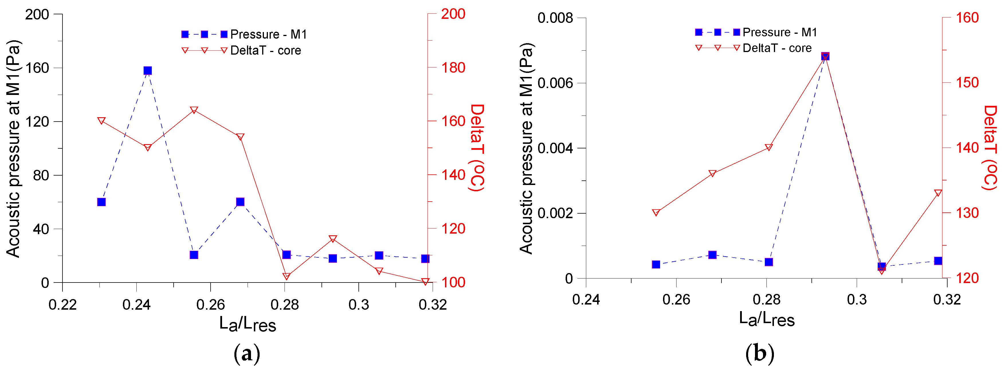
3.2. Experimental Results

Experiments have been carried out by using the setup shown in Figure 7, which emulates a small-scale solar driven standing wave prime mover. The experimental results are not directly related to those obtained by numerical simulations and the comparison between the two is beyond the scope of this paper. The main goal here is to prove that also in “real” conditions, porous cores with parallel pins exhibit better performance in applications with low input powers and small resonator lengths. Obviously, the ideal conditions used in numerical simulations (e.g., perfectly adjustable length of the resonator or changeable working frequency of the device, precise temperature values along the stack, perfectly zero heat conduction along the walls of the resonator, ideal heat exchangers, precise value of the input thermal power) typically result in optimistic estimations of the sound level and acoustic power converted.
The experimental setup is equivalent to that sketched in Figure 1 with the exception represented by the heat exchangers [28]. The hot heat exchanger is replaced by a light parabolic dish collector, which focusses at one end of the porous core the light radiation generated by a 200 W lamp located at 4.5 cm distance. This focalization is possible because of the good transparency of the wall of the resonator to the light radiation. The cold heat exchanger is provided with a copper coil, accommodated around the resonator and carrying cold water at 12 °C, to reduce the heat transfer from the dish to the resonator wall. The length of the resonator is 40 cm and the diameter is 2.8 cm.
The acoustic pressure has been measured in two locations at 3.5 and 6.5 cm away from the resonator open end by using two ¼” pre-amplified G.R.A.S pressure-filled microphones, type 46BD (±0.06 dB uncertainty at 250 Hz). The temperature in proximity of the hot and cold end of the stacks has been measured by using two type-K thermocouples (±2.2 °C uncertainty).
The tests have been carried out for different positions of the porous cores along the resonator, which has been possible because both the dish collector and the heat exchanger could slide along the glass tube, while the distance between the dish and the lamp remains constant.
Two different additive manufactured cores have been tested: one is constituted by predominantly parallel pins and the another one by parallel plates. Both samples have length 3.8 cm. By following the indications provided in Section 2.1.3, the geometrical parameters have been chosen to result in “equivalent” pores for the two stacks: the pins had rp = 9 × 10⁻⁵ m, ratio rp/b = 0.291, supported by a certain number of thin obliquus struts. The parallel plates has semi-thickness h = 9 × 10⁻⁵ m and semi-distance a = 1.98 × 10⁻⁵ m (see Table 1). Also in this case the plates are supported by means thin struts. The constituting material is AISI 316L.
Two examples of the time data acquired during the tests are depicted in Figure 8a,b. The two figures are related to the tests which provided the highest and the smallest acoustic pressure measured for the core with parallel pins. In the first case, the core has been positioned at distance La = 9.5 cm, in the second case at La = 12.0 cm. After a warm-up stage of ~80 s, the temperature differential reaches ~110–130 °C and acoustic instabilities occur, which result in an abrupt increase in the acoustic pressure measured by the microphone M1 at 3.5 cm from the open end. Both the acoustic pressure and the temperature differential increase during the entire test. In case of Figure 8b, the temperature differential between the hot and cold ends remains smaller during the whole test.
By using the two-microphone technique, it is possible to reconstruct the acoustic field (acoustic pressure and particle velocity) [24]. In this way, for the core with pins located at La = 9.5 cm, ~1500 Pa acoustic pressure and ~4 m/s particle velocity have been estimated in proximity of the closed and open end of the resonator, respectively.
In Figure 9, the amplitude of the acoustic pressure measured by the microphone M1 and the temperature differential along the core are plotted for tests at different positions of the cores. The values are obtained by averaging the measurements taken during the last 10 s of each test. Figure 9a,b are, respectively, related to tests with cores with parallel pins and with slits. In both cases, the general trend shows a certain increase in temperature differential at the locations where the emissions increase. It is also confirmed what has been shown by the simulations, i.e., that the optimal position for cores with parallel pins has a small La than the optimal positions for cores with slits. Great differences are noticeable between the performances of the two equivalent cores, with 160 Pa maximum acoustic pressure measured by M1 for the core with pinsand 0.007 Pa maximum acoustic pressure for the core with slits.
This circumstance is better represented in Figure 10, where the contour plots of the spectral components, expressed in sound pressure level, are carried out at each second of the tests for the two cores, once located at the optimal positions (La = 9.5 cm for core with pins and La = 11.5 cm for core with slits) and once at the worst positions (La = 12.0 cm and La = 10.0 cm, respectively). The acoustic emission for tests involving core with pins is always remarkable (Figure 10a,b), up to ~140 dB at 218 Hz, measured by microphone M1, when the core is in the optimal position.
The situation radically changes for the stack with parallel plates because, as visible in Figure 10c,d, which show that, at best, ~80 dB of rather fragmented sound is produced around 216 Hz. In other words, no effective thermoacoustic conversion takes place when this core is used. Noticeably, the same core with parallel plates has been used in a different setup in the paper [19], consisting of a longer resonator (60 cm length) and larger input heat power delivered by a blowtorch. In that case, ~150 dB have been measured at 132 Hz by a microphone located at 10 cm from the open end, suggesting a good thermoacoustic conversion.
Although the geometrical characteristics of the two cores have been chosen to provide equivalent thermoacoustc behaviors, the experimental results confirm what has been indicated by thermoacoustic simulations: cores with parallel pins work properly also in shorted resonators and with small input heat powers.

4. Discussion

Small thermoacoustic devices can have, in principle, numerous applications ranging from harvesting the heat released by biomass-burning cook stoves to cooling electronic devices in space applications. Nevertheless, there is still a wide margin of development for small thermoacoustic devices for building applications. Different destinations in this area can be foreseen, for instance thermoacoustic generators to supply the huge number of sensors in modern buildings, thus to reduce the amount of necessary cables. Thermoacoustic devices can also be used for air cooling and exploiting sun radiation as input thermal power.
At the present date, the main obstacles for the use of small thermoacoustic devices in buildings are represented by small input heat powers available and size constraints which limit the length of the resonator. Since the porous core is responsible for the heat-to-acoustic power conversion, it represents the most important part of the engine. For this reason, the study presented here has assessed the potentialities of different cores typologies and shown which one is more suitable for building applications.
Although cores with parallel pins are not new, manufacturing issues have limited their diffusion and the number of related studies is quite limited. Nowadays, with the advent of modern techniques for additive manufacturing, the production issues have been largely overcome. Cores with parallel pins and cores provided with slits and circular tubes have been thoroughly studied in this paper. The method used for the assessment of the thermoacoustic performance of the cores overcomes the rather qualitative approach provided by previous studies. It consists of a detailed comparison of the best performance exhibited by each core typology and it shows that cores with parallel pins represent the best solution for the problem tackled here.
Future investigations will involve the use of additive manufactured lattice cells with different pin orientations, the optimization of pin-based core geometries and the use of alumina as manufacturing material.

5. Conclusions

In this paper a “fair” comparison between the thermoacoustic performance of different core typologies, including cores with circular tubes, with slits and with parallel pins, has been provided. Thus, the best solution for small thermoacoustic devices in building applications has been suggested. The following steps have been undertaken:
  • The geometrical characteristics of different cores (diameter of the inner tubes, width of the slits, pin diameter and porosities of the cores) have been chosen to result in “equivalent” thermo-viscous behavior.
  • The behavior of each core has been modelled by means of one dimensional thermoacoustic simulations which have been included in a numerical optimization procedure.
  • The optimization procedure has been able to find, per each core analyzed, the engine configuration (length of the resonator, operating frequency and position of the core) which maximizes the acoustic power converted from a fixed small input thermal power. The input power used in the simulations is limited to the range 50–150 W.
The numerical procedure has shown that cores with parallel pins provide the maximum acoustic power by using the smallest length of the resonator. As a consequence, these cores are the best candidates to meet the power and size constraints in buildings. To strengthen this conclusion, a further step has been carried out:
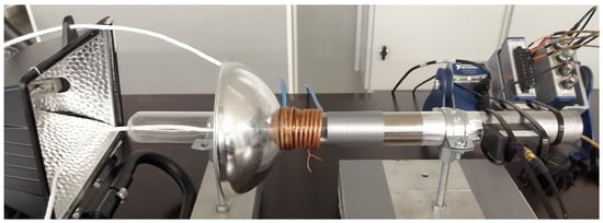
  • An experimental setup has been used to emulate a small-scale solar-driven standing wave prime mover. The setup is equipped with a relatively short resonator (40 cm length) and the input thermal power is delivered by the focussed light of a small projector. An additive manufactured core with parallel pins has been tested at different positions in the resonator and compared with an equivalent core provided with rectangular slits.
The experiments confirmed the trend delineated by the numerical procedure. In fact, for the small thermal power used in the tests, the acoustic emission of the core with parallel pins is remarkable (up to 140 dB close to the open end) and steady over time, while that of the core with slits is negligible (~80 dB) and unsteady.

Author Contributions

Conceptualization, F.A.; methodology, R.D.; numerical simulations, E.D.G., validation and formal analysis, M.N.; writing—original draft preparation, F.A.; writing—review and editing, R.D., E.D.G., M.N. All authors have read and agreed to the published version of the manuscript.

Funding

This research has been funded by: PoC grant EAG28, Smart micro-perforated silencer for heat, ventilation and air conditioning systems financed by Estonian Research Council. Estonian Centre of Excellence in Zero Energy and Resource Efficient Smart Buildings and Districts, ZEBE, grant 2014- 2020.4.01.15-0016 funded by the European Regional Development Fund. Italian Ministry of University and Research (MIUR): Project number PRIN 2017JP8PHK.

Conflicts of Interest

The authors declare no conflict of interest.

Nomenclature

SymbolDescription
aSemi width of the slit
ACross section area of the pore
AfluidFluid area of the core cross section
AsolidSolid area of the core cross section
AwetWet area of the core
AkThermal diffusion area within the pore
AvViscous diffusion area within the pore
b= y0rp
cSpeed of sound
cpIsobaric heat capacity per unit mass of the fluid
csIsobaric heat capacity per unit mass of the solid frame
CXCold heat exchanger
dSemi-distance between two adiacent tubes
DrDiameter of the resonator and of the core
E ˙ 2 Time averaged acoustic power per unit are of the fluid
fkSpatially averaged temperature function within the pore
fk,sSpatially averaged temperature function of the solid part of the pore
fvSpatially averaged viscosity function within the pore
gGain/attenuation constant
hSemi thickness of the plate
H ˙ 2 Total thermal input power
HXHot heat exchanger
HRHydraulic radius
HVACHeat, ventilation and air conditioning
Imaginary part
kThermal conductivity
LaDistance between the hot end of the stack and the closed end of the resonator
LrLength of the resonator
MFigure of merit
M1 and M2Microphone 1 and 2
p and p1Pressure and fluctuating pressure
pmMean pressure
PrPrandtl number
rpRadius of the pin
RDiameter of a tube
ReReal part
r0Radius of the circle inscribed in the hexagonal pattern of pins
r1Radius of the circle inscribed in the square pattern of pins
rvViscous resistance per unit length
rkThermal relaxation conductance per unit length
S(i−1)/δv
ShShear wavenumber
s’(i+1)/δv
T and T1Temperature and fluctuating temperature
TPeriod of the acoustic oscillation
TAHEThermo acoustic heat engine
TC1, TC2Thermocouple 1, 2
u and u1Particle velocity, fluctuating particle velocity
VfluidVolume of fluid in the core
VsolidVolume of solid in the core
VtotalTotal volume of the core
VkThermal diffusion volume
VvViscous diffusion volume
y0Semi distance between adjacent pins in hexagonal pattern
y1Semi distance between adjacent pins in square pattern
γSpecific heat ratio
ΔTcCritical temperature differential
Greek letters
εsHeat capacity ratio
εs,c, εs,s and εs,pHeat capacity ratios of circular pore, slit and pin array pore
δkThermal boundary layer
δvViscous boundary layer
kThermal diffusivity
Λ’Thermal characteristic length
μDynamic viscosity
ηGlobal efficiency
ΠPerimeter of the cross section of the pore
ρ and ρmFluid density and mean fluid density
ϕPorosity
ϕwPhase between acoustic pressure and particle velocity
ωAngular frequency
Subscripts
cCircle
pPin
sSlit
mMean
1First order
2Second order

References

  1. Kurnitski, J. Technical definition of nearly zero energy buildings. REHVA J. 2013, 2013, 22–28. [Google Scholar]
  2. Piccolo, A. Study of standing-wave thermoacoustic electricity generators for low-power applications. Appl. Sci. 2018, 8, 287. [Google Scholar] [CrossRef] [Green Version]
  3. Hong, B.-S.; Lin, T.-Y. System identification and resonant control of thermoacoustic engines for robust solar power. Energies 2015, 8, 4138–4159. [Google Scholar] [CrossRef]
  4. Hariharan, N.M.; Shvashanmugam, P.; Kasthurirengam, S. Experimental investigation of a thermoacoustic refrigerator driven by a standing wave twin thermoacoustic prime mover. Int. J. Refrig. 2013, 36, 2420–2425. [Google Scholar] [CrossRef]
  5. Timmer, M.A.G.; de Blok, K.; van der Meer, T.H. Review on the conversion of thermoacoustic power into electricity. J. Acoust. Soc. Am. 2018, 143, 841–857. [Google Scholar] [CrossRef] [Green Version]
  6. Olivier, C.; Penelet, G.; Poignand, G.; Lotton, P. Active control of thermoacoustic amplification in a thermo-acoustic-electric engine. J. Appl. Phys. 2014, 115, 174905-1-6. [Google Scholar] [CrossRef] [Green Version]
  7. Swift, G.W. Thermoacoustics—A Unifying Perspective for Some Engines and Refrigerators, 2nd ed.; ASA Press Springer: Berlin/Heidelberg, Germany, 2002. [Google Scholar]
  8. Kabral, R.; Rämmal, H.; Lavrentjev, J. Acoustic studies of micro-perforates for small engine silencers. SAE Tech. Pap. 2012, 32, 107. [Google Scholar] [CrossRef]
  9. Lavrentjev, J.; Rämmal, H. Acoustic study on motorcycle helmets with application of novel porous materials. SAE Tech. Pap. 2019, 32, 0531. [Google Scholar]
  10. Rott, N. Damped and thermally driven acoustic oscillations in wide and narrow tubes. Z. Angew. Math. Phys. 1969, 20, 230–243. [Google Scholar] [CrossRef]
  11. Arnott, W.P.; Bass, H.E.; Raspet, R. General formulation of thermoacoustics for stacks having arbitrarily shaped pore cross sections. J. Acoust. Soc. Am. 1991, 90, 3228–3237. [Google Scholar] [CrossRef]
  12. Hofler, T.J. Thermoacoustic Refrigerator Design and Performance. Ph.D. Thesis, Physics Department, University of California, San Diego, CA, USA, 1986. [Google Scholar]
  13. Dragonetti, R.; Napolitano, M.; Di Filippo, S.; Romano, R. Modeling energy conversion in a tortuous stack for thermoacoustic applications. Appl. Therm. Eng. 2016, 103, 233–242. [Google Scholar] [CrossRef]
  14. Napolitano, M.; Romano, R.; Dragonetti, R. Open-cell foams for thermoacoustic applications. Energy 2017, 138, 147–156. [Google Scholar] [CrossRef]
  15. Swift, G.W.; Keolian, R.M. Thermoacoustics in pin-array stacks. J. Acoust. Soc. Am. 1993, 94, 941–943. [Google Scholar] [CrossRef]
  16. Tu, Q.; Zhang, X.; Chen, Z.; Guo, F. Design of miniature thermoacoustic refrigerator with pin-array stack. Acta Acust. United Acust. 2006, 92, 16–23. [Google Scholar]
  17. Matveev, K. Thermoacoustic energy analysis of transverse-pin and tortuous stack at large acoustic displacements. Int. J. Therm. Sci. 2010, 49, 1019–1025. [Google Scholar] [CrossRef]
  18. Asgharian, B.; Matveev, K.I. Influence of finite heat capacity of solid pins and their spacing on thermoacoustic performance of transverse-pin stacks. Appl. Therm. Eng. 2014, 62, 593–598. [Google Scholar] [CrossRef]
  19. Auriemma, F.; Holovenko, Y. Performance of additive manufactured stacks in a small scale thermoacous-tic engine. SAE Tech. Pap. 2019, 1, 1534. [Google Scholar] [CrossRef]
  20. Auriemma, F.; Holovenko, Y. Use of selective laser melting for manufacturing the porous stack of a ther-moacoustic engine. Key Eng. Mater. 2019, 799, 246–251. [Google Scholar] [CrossRef]
  21. Babaei, H.; Siddiqui, K. Design and optimization of thermoacoustic devices. Energy Convers. Manag. 2008, 49, 3585–3598. [Google Scholar] [CrossRef]
  22. Hariharan, N.M.; Shvashanmugam, P.; Kasthurirengam, S. Influence of stack geometry and resonator length on the performance of thermoacoustic engine. Appl. Acoust. 2012, 73, 1052–1058. [Google Scholar] [CrossRef]
  23. Majak, J.; Kuttner, F.; Pohlak, M.; Eerme, M.; Karjust, K. Application of evolutionary methods for solving optimization problems in engineering. In Proceedings of the NordDesign, NordDesign Conference, Tallinn, Estonia, 21–23 August 2008; pp. 39–48. [Google Scholar]
  24. Majak, J.; Pohlak, M.; Karjust, K.; Eerme, M.; Kurnitski, J.; Shvartsman, B.S. New high order Haar wavelet method: Application to FGM structures. Compos. Struct. 2018, 201, 72–78. [Google Scholar] [CrossRef]
  25. Tiikoja, H.; Auriemma, F.; Lavrentjev, J. Damping of acoustic waves in straight ducts and turbulent flow conditions. SAE Tech. Pap. 2016, 1, 1816. [Google Scholar] [CrossRef]
  26. Champoux, Y.; Allard, J.F. Dynamic tortuosity and bulk modulus in air-saturated porous media. J. Appl. Phys. 1991, 70, 1975–1979. [Google Scholar] [CrossRef]
  27. Johnson, D.L.; Koplik, J.; Dashen, R. Theory of dynamic permeability and tortuosity in fluid-saturated porous media. J. Fluid Mech. 1987, 176, 379–402. [Google Scholar] [CrossRef]
  28. Piccolo, A.; Sapienza, A.; Guglielmino, C. Convection heat transfer coefficients in thermoacoustic heat exchangers: An experimental investigation. Energies 2019, 12, 4525. [Google Scholar] [CrossRef] [Green Version]
Figure 1. Schematic of an open standing-wave THAE prime mover.
Energies 13 02941 g001
Figure 2. Thermal diffusion region (parallel red lines) and viscous diffusion region (blue areas) in cores provided with convex (a) and concave cores (b).
Energies 13 02941 g002
Figure 3. Rott’s functions for circular tube, slit and pin arrays.
Energies 13 02941 g003
Figure 4. Example of simulations for optimal configuration assessment. Input data: Q = 50 W, f = 140 Hz, core with parallel pins, temperature at cold end of the stack (TC) = 30 °C, and that at the hot end (TH) = 200 °C. (a) Simulated temperature at cold end and corresponding optimal lengths of the core for different positions along the resonator, (b) simulated acoustic power at different positions for cores provided with length Ls previously determined.
Energies 13 02941 g004
Figure 5. Acoustic power delivered by different porous cores for different input heat powers (50, 100 and 150 W).
Energies 13 02941 g005
Figure 6. Optimization results for different input powers (50, 100 and 150 W). (a) Optimal length of the core. (b) Optimal position of the core.
Energies 13 02941 g006
Figure 7. Experimental setup utilized to emulate a small-scale sun-powered thermoacostic prime mover for building applications.
Energies 13 02941 g007
Figure 8. Time domain values of acoustic pressure measured by microphone M1 and temperatures measured in proximity of the core ends. (a) Optimal position of the core, La = 9.5 cm. (b) Non-optimal position of the core, La = 12.0 cm.
Energies 13 02941 g008
Figure 9. Ten second averaged acoustic pressure (at microphone M1) and pressure differential along the core for different positions. (a) Core with parallel pins. (b) Core with slits.
Energies 13 02941 g009
Figure 10. Spectral components in time, expressed in sound pressure level, of the sound measured by microphone M1. Results for porous core with parallel pins: (a) La = 9.5 cm; (b) La = 11.5 cm. Results for porous cores with slits: (c) La = 12.0 cm; (d) La = 10.0 cm.
Energies 13 02941 g010
Table 1. Geometrical and viscous-thermal relationships between the cores studied in this paper.
Cell TypeΛ’ϕDistance between PinsMinimum Characteristic Dimension of Solid Skeleton
Energies 13 02941 i001
Parallel pins (hexagonal pattern)
( 2 3 y 0 2 π r p 2 ) 2 π r p ( 2 3 y 0 2 π r p 2 ) 2 3 y 0 2 y 0 = r 0 π 2 3 r p
Energies 13 02941 i002
Parallel pins (square pattern)
( 4 y 1 2 π r p 2 ) 2 π r p ( 4 y 1 2 π r p 2 ) 4 y 1 2 y 1 = r 1 π 2 r p
Energies 13 02941 i003
Infinite rectangular slit
2 a 2 a 2 a + 2 h = Λ 2 a + 2 h 2 h = Λ ϕ 2 a
Energies 13 02941 i004
Circular tubes (hexagonal pattern)
R π R 2 2 3 ( d + R ) 2 2 d
Table 2. Geometrical data of the porous cores studied and compared in this paper.
Parallel PinsSlitsCircular Tubes
rp/bΛ’ [m]ϕa [m]h [m]R [m]d [m]
0.0019.05 × 101 1.0004.51 × 101 4.50 × 10⁻⁵ 9.02 × 11 4.50 × 10⁻⁵
0.019.18 × 10−1 1.0004.59 × 10−1 4.50 × 10⁻⁵ 9.18 × 10⁻¹ 4.50 × 10⁻⁵
0.053.96 × 10−2 0.9981.98 × 10−2 4.50 × 10⁻⁵ 3.96 × 10⁻² 4.50 × 10⁻⁵
0.11.08 × 10−2 0.9925.40 × 10−3 4.50 × 10⁻⁵ 1.08 × 10⁻² 4.50 × 10⁻⁵
0.291.69 × 10−3 0.9498.45 × 10−4 4.50 × 10⁻⁵ 1.69 × 10⁻³ 4.50 × 10⁻⁵
0.57.20 × 10−4 0.8893.60 × 10−4 4.50 × 10⁻⁵ 7.20 × 10⁻⁴ 4.50 × 10⁻⁵
12.70 × 10⁻⁴ 0.7501.35 × 10−4 4.50 × 10⁻⁵ 2.70 × 10⁻⁴ 4.50 × 10⁻⁵
1.51.6 × 10−4 0.6408.00 × 10−5 4.50 × 10⁻⁵ 1.60 × 10⁻⁴ 4.50 × 10⁻⁵
21.13 × 10⁻⁴ 0.5565.63 × 10−5 4.50 × 10⁻⁵ 1.13 × 10⁻⁴ 4.50 × 10⁻⁵

