Article

Performance Improvement of a Hydraulic Active/Passive Heave Compensation Winch Using Semi Secondary Motor Control: Experimental and Numerical Verification

by
Geir-Arne Moslått
1,*,
Michael Rygaard Hansen
2 and
Damiano Padovani
2
1
Department of Lifting and Handling, National Oilwell Varco, 4639 Kristiansand, Norway
2
Department of Engineering Sciences, University of Agder, 4879 Grimstad, Norway
*
Author to whom correspondence should be addressed.
Energies 2020, 13(10), 2671; https://doi.org/10.3390/en13102671
Submission received: 28 April 2020 / Revised: 16 May 2020 / Accepted: 18 May 2020 / Published: 25 May 2020
(This article belongs to the Special Issue Intelligent Fluid Power Drive Technology)

Abstract

:
In this paper, a newly developed controller for active heave compensated offshore cranes is compared with state-of-the-art control methods. The comparison is divided into a numerical part on stability margins as well as operational windows and an experimental validation of the expected performance improvement based on a full-scale testing on site with a crane rated to 250 metric tons. Such a crane represents the typical target for the new control method using a combination of active and passive hydraulic actuation on the main winch. The active hydraulic actuation is a hydrostatic transmission with variable-displacement pumps and variable-displacement motors. The new controller employs feedforward control of the motors’ displacement so that the window of operation is increased and, simultaneously, oscillations in the system are markedly reduced.

1. Introduction

There are high demands for motion compensated offshore cranes today, mostly related to oil and gas, but also the offshore wind industry. The purpose of motion compensation is to decouple the vessel motion from the connected payload. There are two main categories of compensation. The first is a full 3D compensation (horizontal and vertical plane), while the second is a 1D compensation (vertical plane alone). The most common solution is equipping the crane with a 1D compensation system, and the vessel with a dynamic positioning system keeps the position in the horizontal plane. This approach works very well for most subsea operations since the payload motion in the horizontal plane due to the vessel’s roll, pitch, and yaw becomes insignificant by the dampening effect when the payload is below the sea surface. If 1D or 3D compensation is used, the most common methods for the vertical compensation of the motion are controlling the wire speed in the winch or using a passive motion compensator mounted directly on the crane’s hook. The wire’s speed control can be done with the drum directly or with a dedicated cylinder [1]. When the system is drum controlled, it is usually done with a hydraulic transmission that can be categorized into five types [1,2,3,4]:
  • Primary controlled systems with variable-displacement pumps and fixed-displacement motors (VPFM) operated in the closed-circuit configuration.
  • Primary controlled systems with variable-displacement pumps and variable-displacement motors (VPVM) operated in the closed-circuit configuration.
  • Secondary control with a VPVM system operated in closed-circuit configuration with an in-line accumulator ensuring constant pressure.
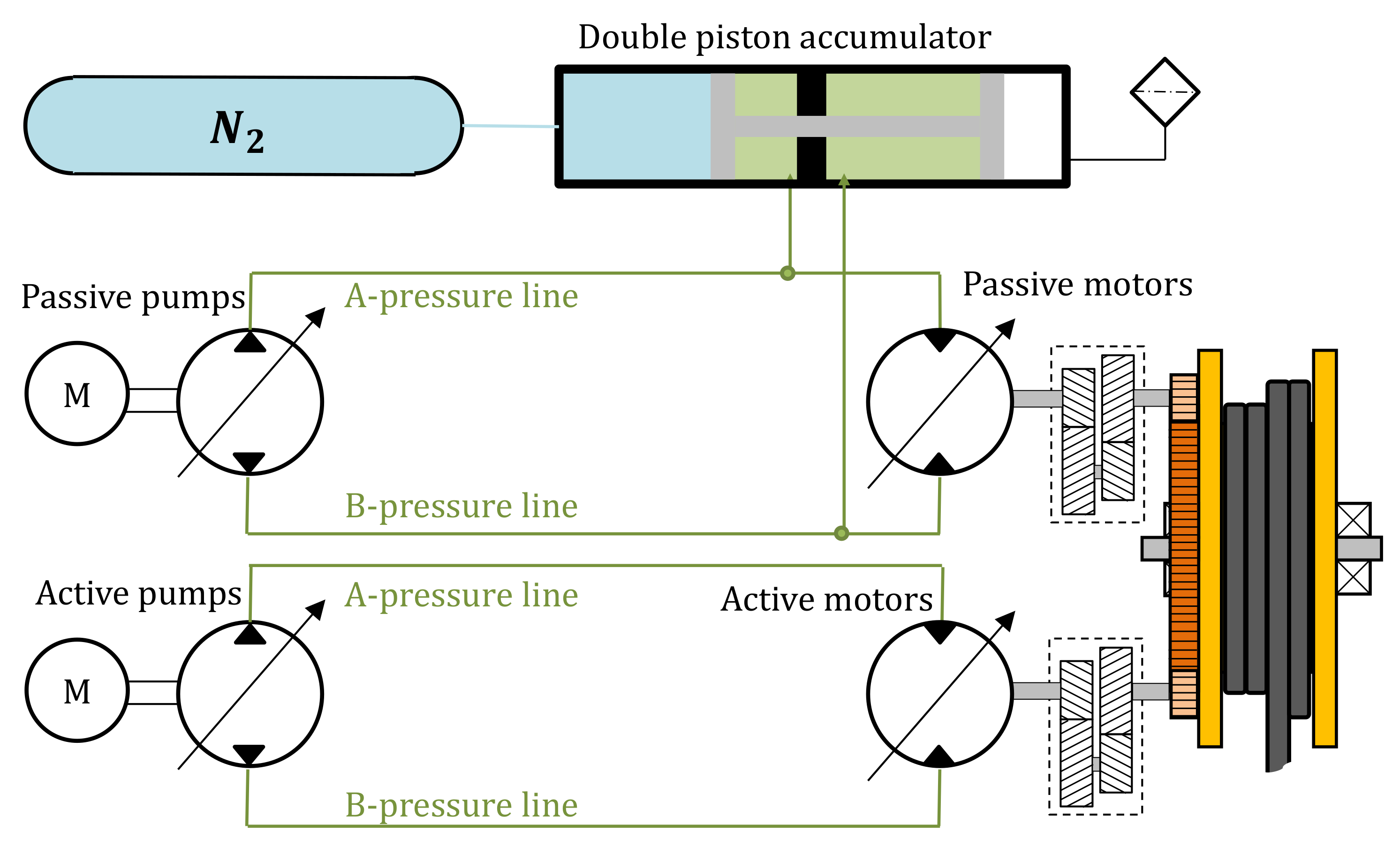
  • Active/passive hydraulic systems (also known as “hybrid”) with two VPVM systems where one of them is secondary controlled, and the other one is primary controlled.
  • Open-circuit systems with a power supply and a pressure-compensated proportional valve.
The active/passive systems dominate the market when looking at crane sizes with lifting capacity above 100 tons. Pure secondary controlled systems are also an option and could be equipped with both analog or digital displacement motors. Although digital displacement motors are not a mature solution at the moment [5], these systems are well suited for the recuperation of energy when subjected to negative loads [3,6,7]. The secondary control units benefit from higher speed capabilities, and improved system response compared to the classic primary pump-controlled systems. Secondary control was introduced in 1977 [8] for hydraulic systems but has still not obtained widespread use in the offshore crane market. The main disadvantage is the demand for expensive components such as over-center hydraulic motors or digital displacement hydraulic motors. The active/passive system is chosen for further investigation in this paper due to its widespread use. Specifically, the active circuit has untapped improvement potential [9]. In the active part of an active/passive system, the motors are equipped with an adjustable displacement. However, the most common active heave compensation strategy is to utilize the motors as if they were fixed-displacement units (like a VPFM system). This approach results in the pumps used as the control element, while the motors’ displacement is not adjusted continuously but simply set to fixed values based on the number of wire layers on the drum. When VPFM systems are used in active heave compensation (AHC), the maximum exploitable speed for the winch is limited because the fixed-displacement motors are set based on the high-torque scenarios. As a result, systems that use this classic control method often have different modes to cover a greater speed range. Typically, different modes comprise a normal-speed mode that allows full load capacity, and a high-speed mode. The high-speed mode operates with reduced motors’ displacement; therefore, the winch gets a lower allowable safe working load (SWL).
Linear control approaches for hydrostatic transmission (HST) systems, like classic PID controllers, are still commonly used in industrial applications. However, the HST is a nonlinear system, and researchers have tried to address this for several years. One of these strategies utilizes nonlinear backstepping methods [10,11]. Others strategies introduce adaptive control techniques [12,13,14,15,16,17], or model-based control [18,19,20,21,22]. Some attempts directly towards active heave compensated systems have also been investigated, like fuzzy PI or PID controller [23,24], position controller with tension feedback [25,26], and cascade controllers [27]. To control the winch-drives, one should consider the use of fault-tolerant control (FTC) approaches [12,28]. There are two main categories of FTC [29], namely, active and passive. The cranes from National Oilvell Varco are, in principle, equipped with parts from both, but should, in general, be seen as a system equipped with passive FTC. The AHC controller is a robust linear controller, which is a type of passive FTC. However, the cranes could also be equipped with systems that detect critical errors, such as sensor faults or power loss. In the event of a power failure, the crane uses parameter reconfiguration in the controller, which is a type of active FTC. E.g., if one of the three hydraulic power units shuts down, the fault is detected, the unit gets isolated, and the control parameters are reconfigured (the process is done on-the-fly without stopping the AHC operation). Further, it has been some interest regarding the vessel’s motion prediction [30,31] that can be used to improve the controller performance or to predict future events. However, all the aforementioned research is concerned with system performance optimization by exclusively focusing on either the primary control unit or the secondary control unit. In [32] such a dual approach was introduced, and it was shown that optimized control of the pumps’ and motors’ displacement could yield a better trade-off between response speed and efficiency. The results were, however, not experimentally verified. Another strategy to improve the performance of an HST system for an AHC winch system was introduced in [9]. It highlighted that the dynamical properties of the winch system are highly affected by the motors’ displacement, and maximizing them at low speed would result in significant improvements in pressure-peaks and control error. The proposed control strategy actively adjusts the motors’ displacement and, at the same time, keep the classic primary pump-controller. Thus, the system is a mix of secondary control and primary control and called semi secondary control (SSC). Since the displacement in SSC is active and also load sensitive, the need for two or more operational modes is removed as well as the corresponding limitations on the SWL. The results from simulations showed increased performance with regards to the maximum winch velocity and permitted load. It also improved the dynamic response of the winch, which resulted in a smaller control error and smoother winch motion.
Even though the SSC system has been introduced, no systematic evaluation of the new system has been put forward, and no full-scale experimental verification of the improved performance has been presented. Both these aspects are, therefore, addressed in this paper. A description of the hydraulic and mechanical winch system is given in the next section, together with a portrayal of the new controller. In the third section, the new controller’s effect on stability is reviewed. Then, in section four, a comparison of the classic control method and the new SSC approach are compared in a simulation model. Section five continues with more comparisons that originated from field tests, followed by the conclusions in section six.

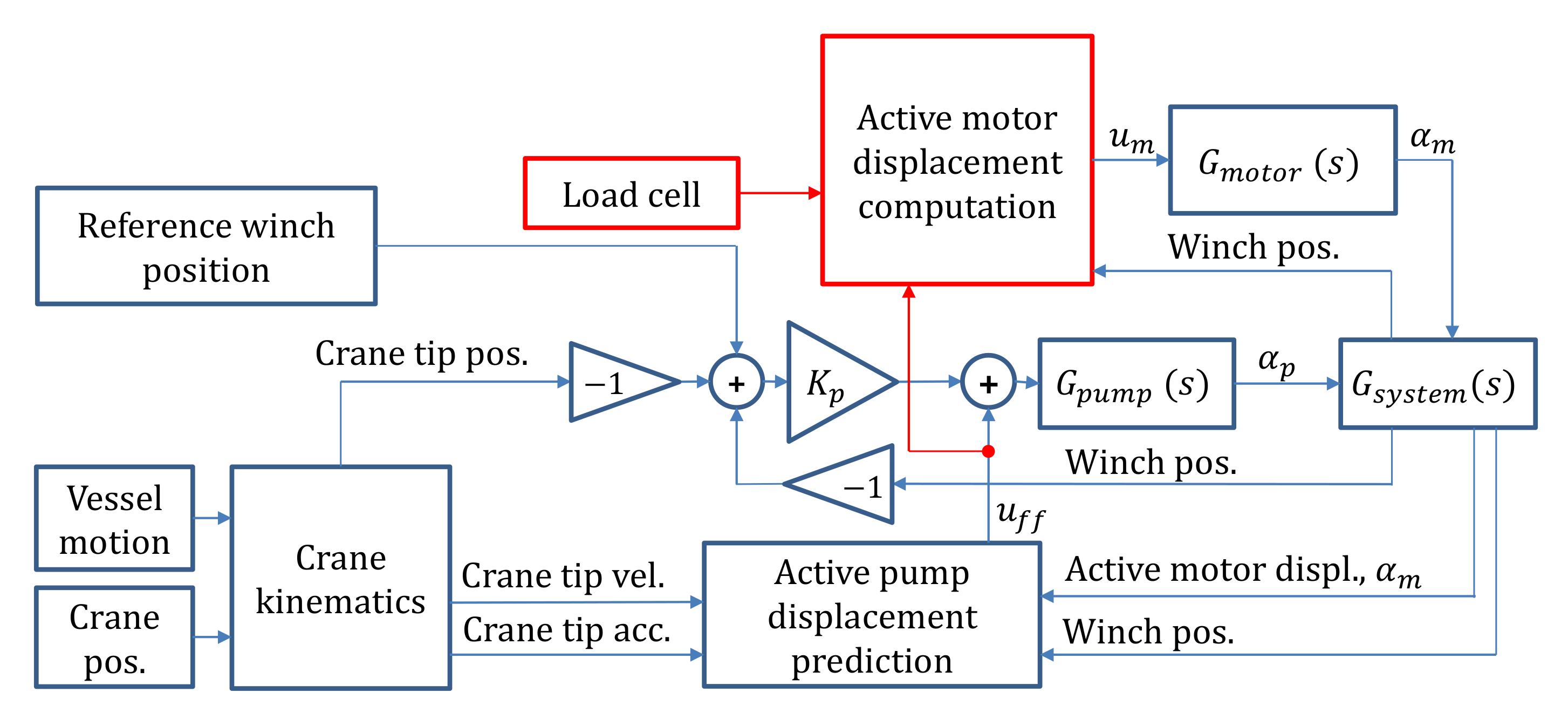
2. Control Algorithm and System Description

The VPVM system under investigation consists of these main components: three over-center variable-displacement pumps for the active side and three for the passive side, five active motors, sixteen passive motors, and a large double piston accumulator connected to nine pressure vessels. The motors are attached to a two-stage gear-transmission, followed by a pinion connected to a ring-gear on the rotating drum. A simplified schematic of the hydraulic transmission is shown in Figure 1, and the total sizes of the main components can be seen in Table 1.
The classic AHC controller works as a VPFM system where the motors’ displacement is only adjusted when the drum layer is changed. The new controller introduced in [9] suggests an active control of the motors’ displacement. The control input is basically a feedforward signal based on the amount of wire on drum, crane’s tip velocity, crane’s tip acceleration, and motors’ displacement.
The control structure is depicted in Figure 2, where the parts marked in red represent changes from the classical PVFM controller.
The classic system’s control uses a conservative fixed value of the motors’ displacement to be able to cope with the required operation, winch stiction, and winch acceleration. The resulting torque peaks when the winch is switching direction (i.e., scenarios with low speed and high acceleration). The new controller is expected to improve the performance compared to the classical controller. One of the main reasons is that the motors are set to maximum displacement whenever the winch is passing zero velocity. This decision will ensure a higher system stiffness and high torque capacity. As a result, lower amplification of the system resonance and smaller pressure peaks are achieved. Considering that the feedforward signal is the most significant part of the pumps’ command signal, it is clear from Figure 3 that the motors’ displacement will be at the maximum value when the pump is passing zero displacement.
Thus, the motors’ displacement is controlled according to Equations (1)–(3):
u m = 1 k v g r e d · D m , m a x D m , m i n D m , m a x ,
k v g r e d = 1 1 u t h r · | u f f | u t h r 1 u t h r , | u f f | u t h r 0 , | u f f | < u t h r .
The relative reduction of the motors’ displacement between the maximum and a dynamically set minimum (load dependent) is referred to as k v g r e d (Equation (2)). If k v g r e d = 1 , it implies that the motors’ displacement is reduced to its minimum allowable displacement, D m , m i n . The factor, k v g r e d , is controlled by the feedforward command, u f f , which is based on the vessel movement, actual displacement, and the exit diameter of the wire on the drum. The threshold-value, u t h r , defines at what point the motors’ displacement should start to be reduced.
The second major benefit of using the variable motors’ displacement control is the increased maximum speed of the winch. At higher speed demand, the torque needed for acceleration is less, and the motors’ displacement can be reduced with low risk of exceeding the admitted pressure levels. The reduction of the displacement dictates a higher velocity capacity as a direct outcome. To ensure that the displacement is not reduced too much, the new controller uses the loadcell sensor (i.e., a measure of the winch load) to calculate a minimum displacement level, D m , c a l c M i n . Additionally, an absolute minimum, D m , a b s M i n , is also set to avoid exceeding the speed limitations of the winch components. The maximum setting of the two defines D m , m i n (Equation (3)).
D m , m i n = m a x ( D m , a b s M i n , D m , c a l c M i n )
Due to the dynamic adjustment of the motors’ displacement, the new controller will be able to reach higher wire velocity without saturating the pumps. An example of this feature is shown in Figure 4. The amount of extra speed that can be obtained will mainly depend on the winch load and minimum allowed motors’ displacement.

3. System Stability

An analysis of both the closed-loop system’s transfer function and the tuning parameter, K p , was performed to investigate the influence of the system changes that the new controller introduces. The system’s governing equations listed in Equations (1)–(11) are the non-linear, time-domain equations. These equations are based on a simplified equivalent hydraulic system representing the active part in the active/passive hydraulic system seen in Figure 1. The controller algorithm described in Equations (1) and (2), where Equation (1) defines the motors’ control signal, u m .
u f f = ( k 1 · v t i p + k 2 · a t i p ) · K w i r e · α m
e = ( v t i p ω m · d D , m a x i h D · 2 · K w i r e ) · d t
u p = u f f + K p · e
α ¨ m = w n m 2 · ( u m α m ) 2 · ζ m · w n m · α ˙ m
α ¨ p = w n p 2 · ( u p α p ) 2 · ζ p · w n p · α ˙ p
v w = ω m · d D , m a x i h D · 2 · K w i r e
J m e f f · ω ˙ m = D m , m a x · ( p A p B ) · α m B v · ω m
V A β · ( p ˙ A p ˙ B ) = D p , m a x · ω p · α p α m · D m , m a x · ω m K l e a k · ( p A p B )
The motors’ control signal depends on the feedforward control signal, u f f , from the crane’s tip motion and winch geometry shown in Equation (4). The position control error, calculated in Equation (5), is used with a proportional controller and a feedforward command to control the pumps (Equation (6)). The second-order equations in Equations (7) and (8), describe the response of the pumps’ and motor’s displacement. Equations (9)–(11) represent the dynamics of the hydromechanical system.
When linearizing the above-mentioned set of equations, it is assumed that u t h r < u f f < 1 , and the low-pressure side, p B , is kept constant. Since a linearization is performed around a steady-state velocity, the a t i p will naturally disappear.
U m = 1 1 U t h r · | U f f | · D m , m a x D m , m i n D m , m a x
U f f = k 1 · v t i p ( s s ) · K w i r e · A m + k 1 · V t i p · K w i r e · α m ( s s )
s · E = V t i p W m · d D , m a x i h D · 2 · K w i r e
U p = U f f + K p · E
s 2 · A m = w n m 2 · ( U m A m ) 2 · ζ m · w n m · s · A m
s 2 · A p = w n p 2 · ( U p A p ) 2 · ζ p · w n p · s · A p
V w = W m · d D , m a x i h D · 2 · K w i r e
J m e f f · s · W m = D m , m a x · ( p A ( s s ) p B ) · A m + D m , m a x · α m ( s s ) · P A B v · W m
V A β · P A · s = D p , m a x · w p · A p α m ( s s ) · D m , m a x · W m w m ( s s ) · D m , m a x · A m K l e a k · P A
G v ( s ) = V w V t i p
By the parameter-variation and use of the Routh-Hurwitz criterion on the transfer function G v ( s ) , the K p for a marginally stable system was found, K p ( m s ) . The added motor control is implemented as a pure feedforward, hence stability is not affected as long as the internal displacement controller of the motors are stable (which is assumed in this case). Therefore, the motors’ natural frequency and damping ratio, ω n m and ζ m , have no effect on the system stability. As seen in Figure 4, the new controller could lead to situations with lower displacement settings than the classic controller. Based on parameters from Table 2, Figure 5 shows the relationship between K p ( m s ) and motor displacement.
Compared to the classical control strategy, the main difference with the SSC system is that the displacement is adjusted actively. The displacement in the classical controller is held constant, while in the SSC, the displacement is adjusted due to the winch’s speed command. In Figure 4, the steady-state command signals are plotted for both pumps and motors. It is seen that for most operating conditions, the motors’ displacement will be higher for most wire-speed scenarios. However, the curves will cross at some point, and the SSC will demand a lower motor displacement than the classical controller. The lower motor displacement will reduce the K p ( m s ) compared to the classically controlled system. However, this characteristic is not seen as critical because, in an active heave compensation scenario, the speed demand will be cyclic, and in every cycle, the speed will return to zero. Zero speed demand will give maximum motor displacement and, therefore, also the highest stability margin. In that way, the system will never stay for many seconds in a scenario with low or negative stability margins. Additionally, these systems do not usually demand high K p , and a slight reduction in the stability margin is not seen as a problem.

4. Comparison of the Classic and New Controller

A simulation model is built and verified with field measurements. Further, it is used to compare the two different strategies. The model allows for testing the complete operating range of the winch, which is not always possible to test on the real crane. A map of different load scenarios was created and compared. The load scenarios include loads from 20% to 100% of the SWL, and crane’s tip velocity profiles with peak velocities from 10 m/min to 120 m/min. The performance is reviewed based on three different characteristics, namely the control error, peak pressures, and settling time.

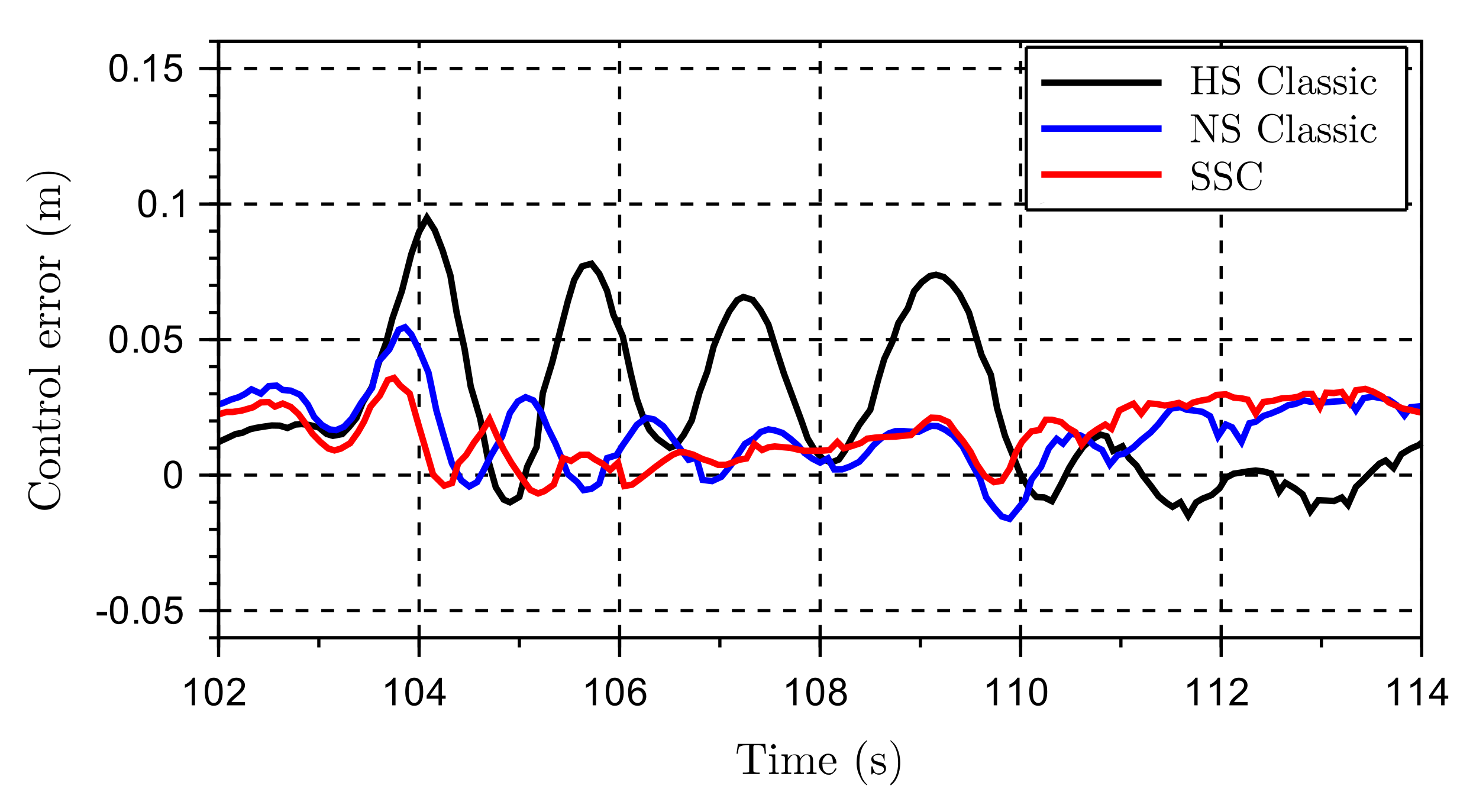
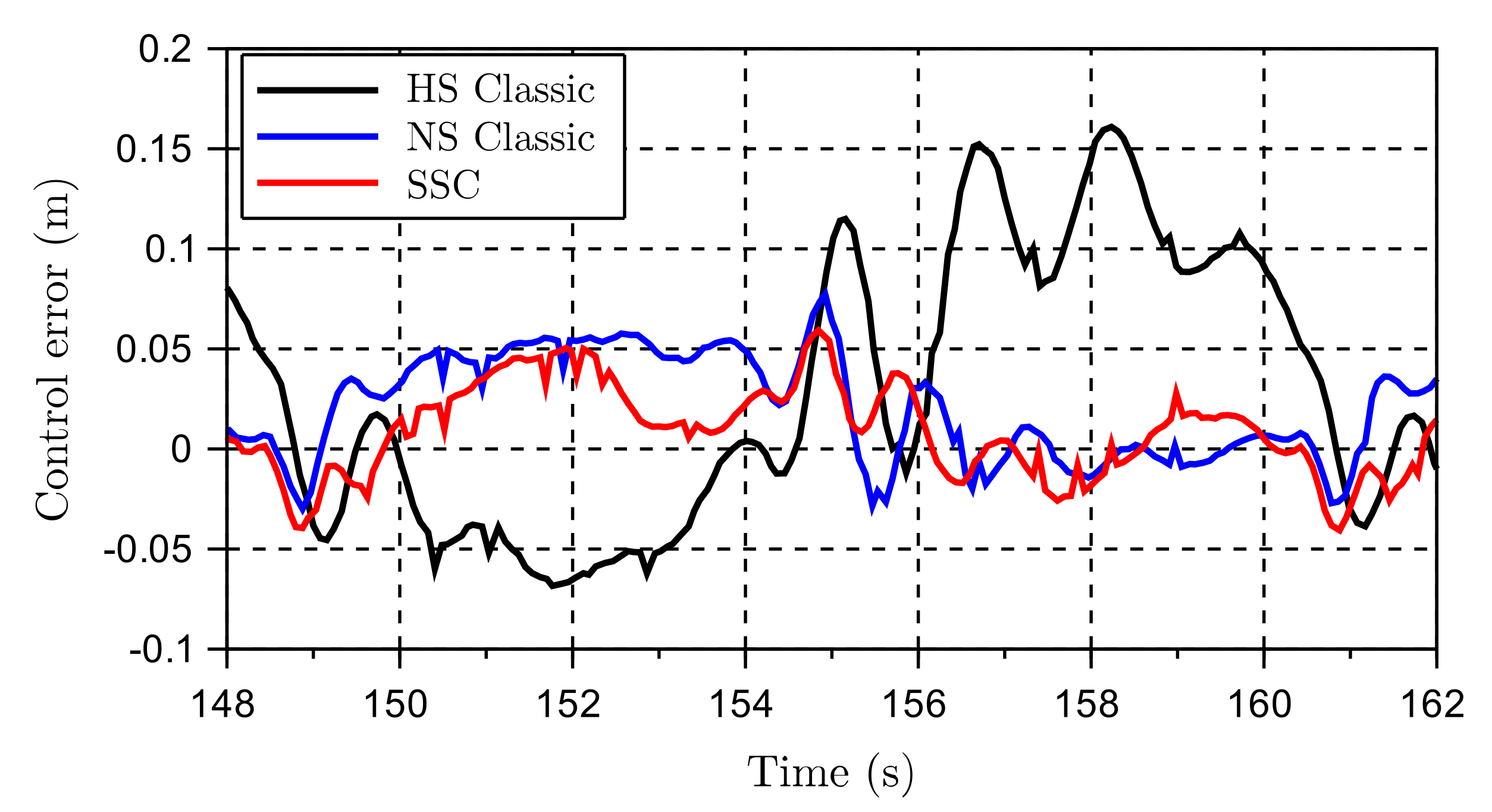
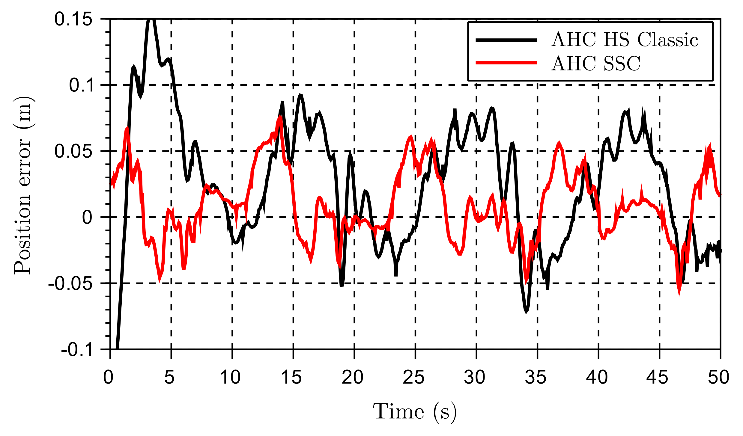
4.1. The Control Error

The test sequence is a representative velocity profile like the one shown in Figure 6. The profile is scaled up and down to match the desired peak velocities so that different conditions are explored. The control error is calculated as the peak-to-peak control error over 20 s (see Figure 7).
The results in Figure 7, show that the classic controller has significantly reduced performance in the high-speed scenarios, and the dark-red areas displays areas where the classic controller is not applicable. In contrast, the SSC strategy show a stable and consistent performance in the whole range.

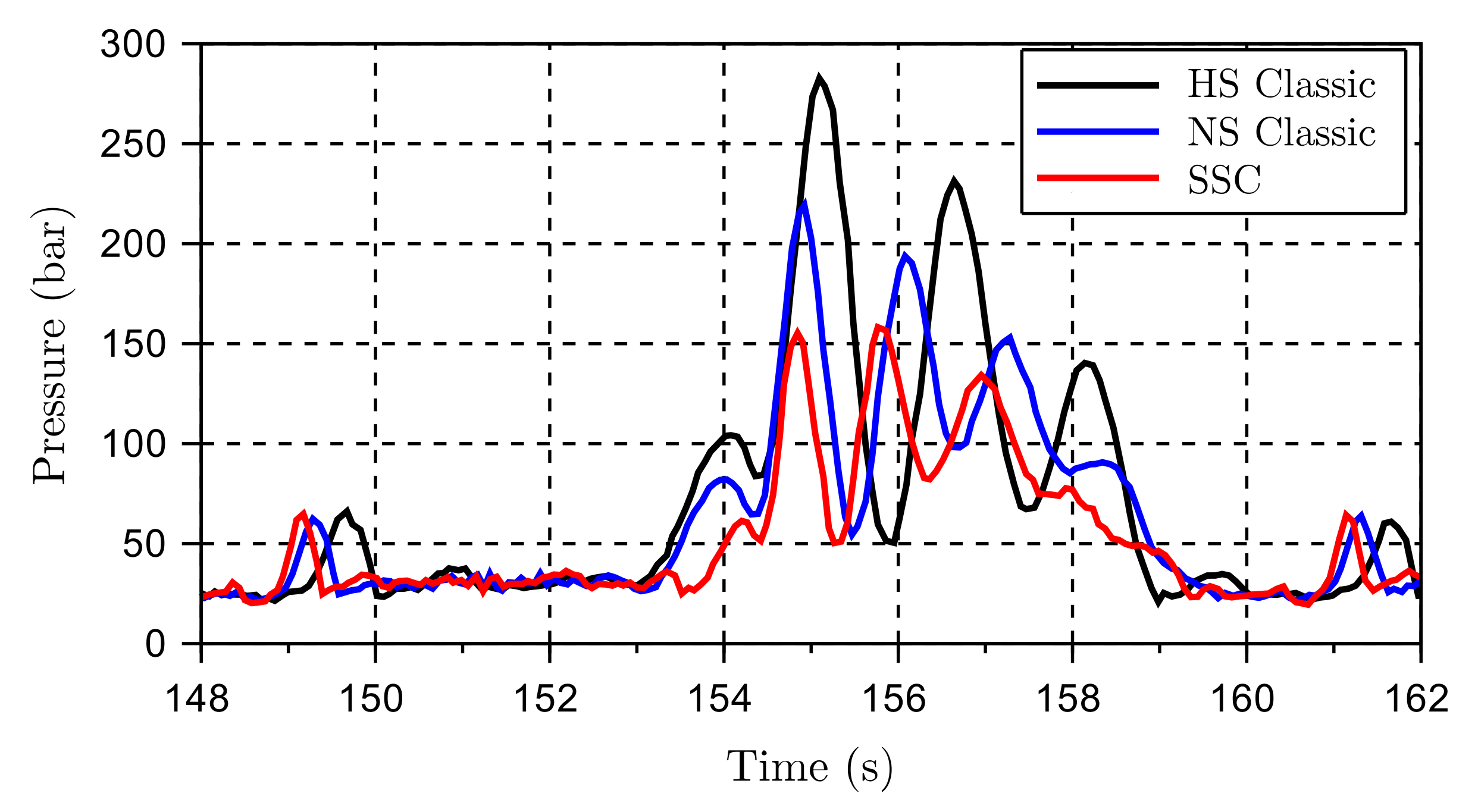
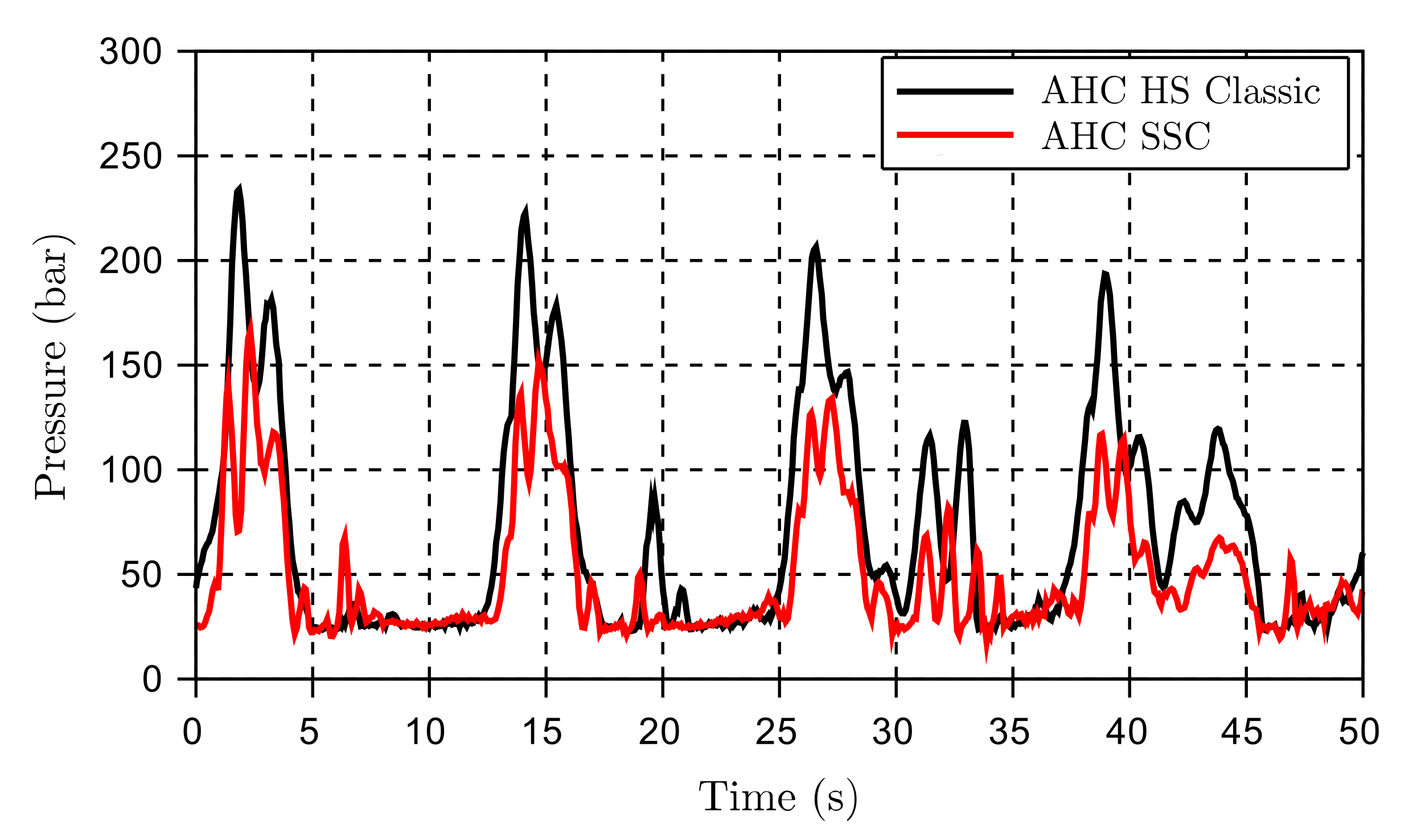
4.2. The Peak Pressures

The peak pressures taking place in the hydraulic system were monitored during the same cycle used for investigating the control error (see Figure 6 and Figure 7). The maximum peak pressure depicted in Figure 8 show that for most cases the differences are small, but in favor of the SCC. The most significant peak pressure reductions are found at velocities above 80 m/min.

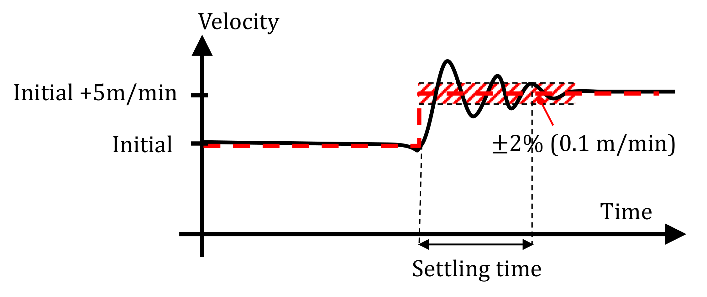
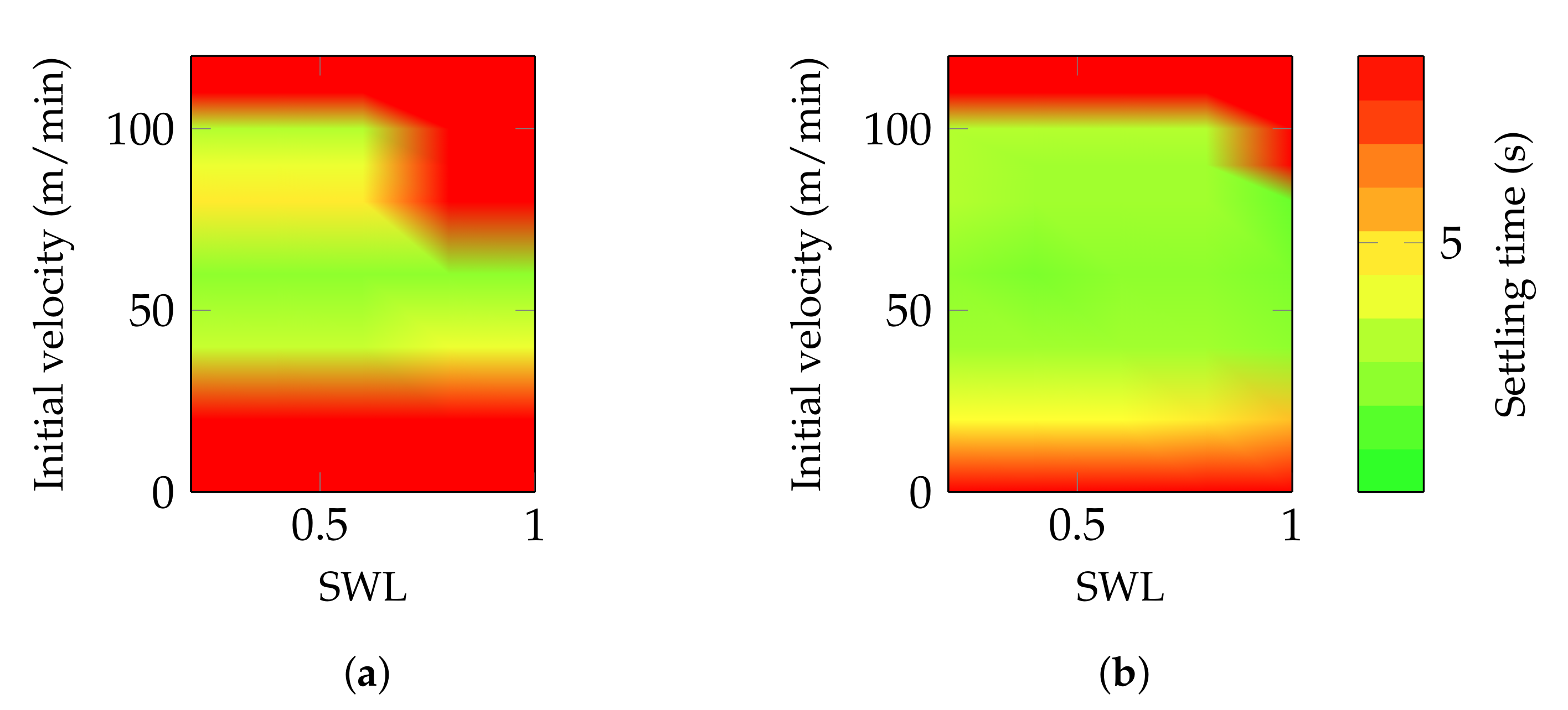
4.3. The Settling Time

Due to the increased motor’s displacement at low speed, the winch is expected to run smoother and give lower settling times. The settling time is tested by setting a fixed wire velocity reference and then step up the reference velocity by 5 m/min. The settling time is defined as the amount of time between the step command and the instant where the velocity is settled close to the target value within a certain tolerance. In this case, this tolerance is 2% of the step size (i.e., 0.1 m/min) as reported in Figure 9.
The results in Figure 10 show a significant improvement when the SSC is applied. The corresponding motors’ displacement, in Figure 11, substantiate the assumptions that improved performance at low speed is highly affected by the motors’ displacement. Additionally, the large displacement variations when using SSC is illustrated compared to the classic controller with only two fixed displacement settings.
As expected, low-speed settling time characterizes the new controller. It is also seen that the new controller performs better at higher speeds and covers part of the map that the classical controller did not. Additionally, it is seen that in the area where the classical controller is close to the speed limitation of the normal-speed mode, around 80 m/min, the SSC performs better.

5. Experimental Results

The full-scale tests performed on a real crane were divided into two main parts. First, the system was tested along a quayside with an empty hook to ensure that the overall functionality and safety could be approved. This step included checking the motors’ displacement response and running the winch in AHC with the simulated crane’s tip motions. Next, a second experiment was conducted offshore with loads up to 200 tons.

5.1. The Quayside Test

The quayside test was conducted with low winch load and simulated crane’s tip motions. The chosen scenario reduces the risk of potential damages to an absolute minimum. Further, the test should reveal how the control of the motors’ displacement performs on the real system and if any unforeseen challenges occur. The test was performed with approximately 15 m of wire paid out and the hook hanging freely in air (Figure 12).

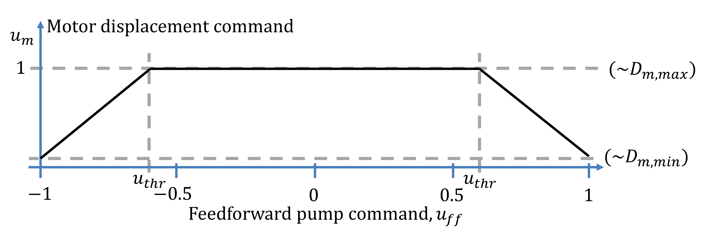
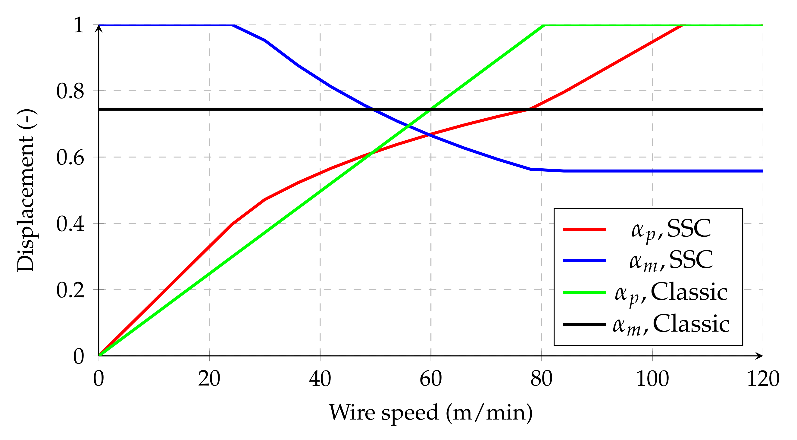
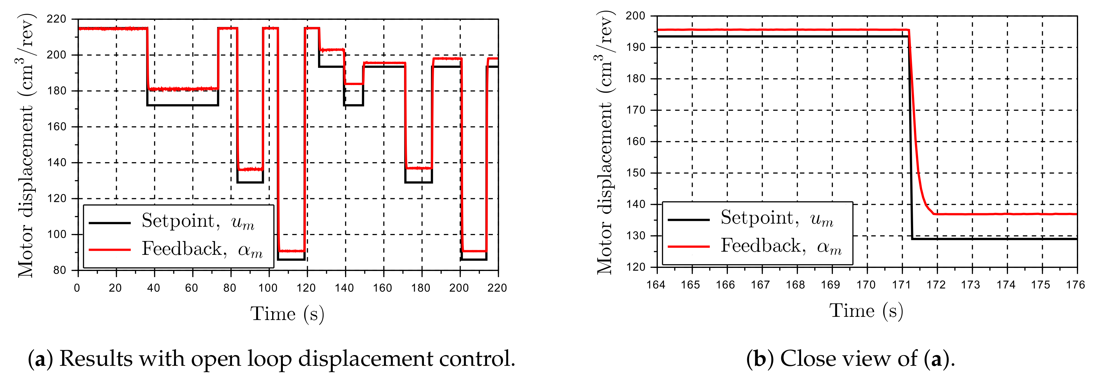
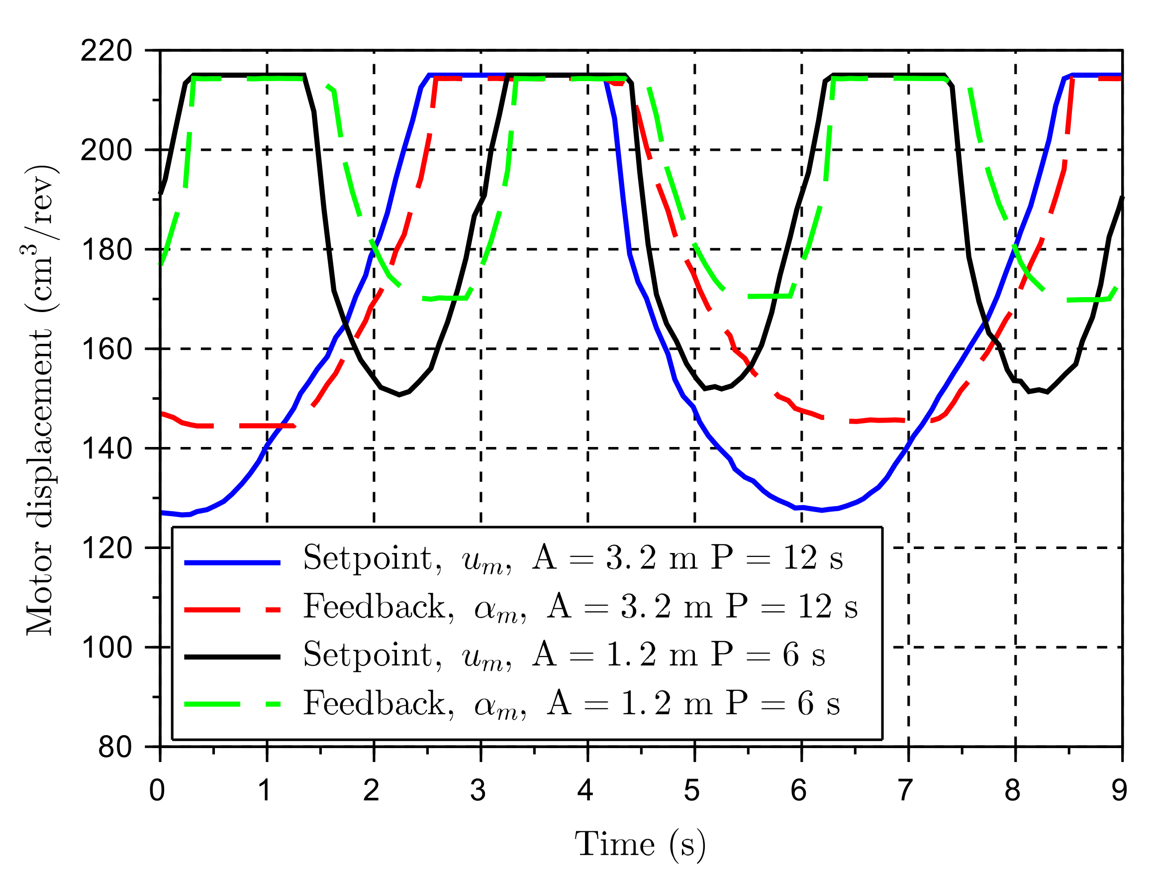
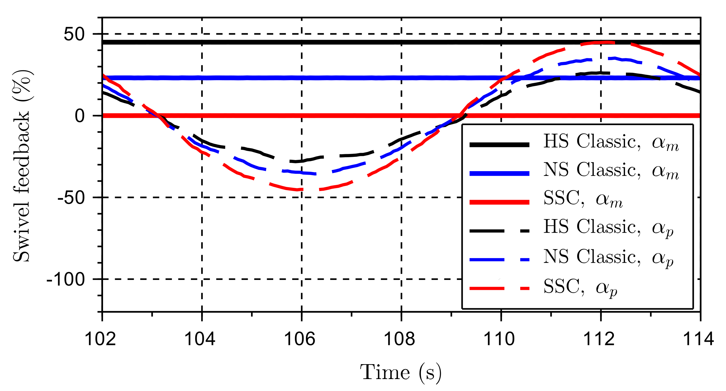
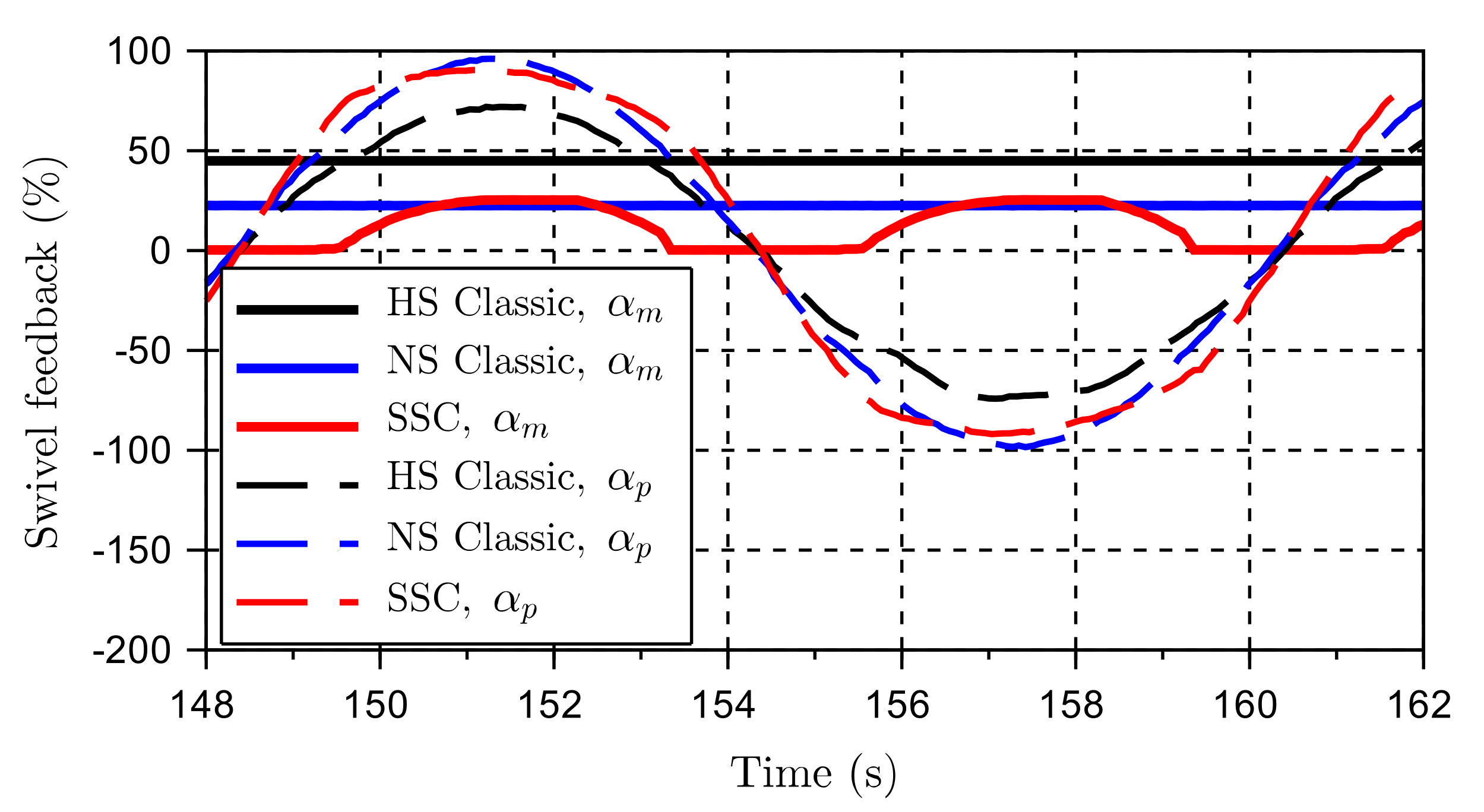
5.1.1. The Control of the Motors’ Displacement

Depending on the particular crane, the inner control of the motors’ displacement is done in closed-loop (CL) with displacement feedback, or open-loop (OL) without feedback. For the optimal displacement control, the CL approach needs to be used. However, due to cost or retrofit limitations, the other options can be preferred. If OL control is used, but the displacement feedback is available, the overall control accuracy is not affected since the actual displacement is always known and can be fed into the heave compensation controller. The downside is that the actual displacement has significant error compared to the displacement reference, affecting the maximum speed capacity. A third option is the OL without feedback. This method undermines the maximum speed capacity compared to the OL with feedback and affects the control error. The control error is now affected because the feedforward command in the heave compensation controller now has to use the motors’ displacement command instead of the measured displacement. Hence, an offset between the actual wire velocity and the desired velocity should be expected. In the crane under investigation, the motors were controlled in OL with feedback, i.e., there is always a certain discrepancy between the commanded and measured displacement, even at steady-state (Figure 13a).
Several tests were conducted to ensure that the motors can change displacement fast enough to track the commanded setting. The motors are generally reacting faster when the CL is used, so the OL control was chosen being the most conservative way to evaluate the new control method. The results with the OL were satisfactory since sufficient displacement variation was achieved in less than one second (Figure 13b). For comparison in a worst-case scenario, the AHC may have to react to a sinusoidal wave with a peak velocity of 110 m/min and the winch working on the outermost layer. If u t h r is set to 0.6, there will be a duration of 1.1 s from when the variable motor control is active to the point of maximum velocity. Therefore, the response time of approximately 1 s is considered more than adequate.
The downside of the OL control is represented by the hysteresis and offset between desired and actual displacement. The offset is not critical since all the motors have a displacement feedback sensor. It introduces some challenges when the system is trying to reach its full capacity, i.e., maximum pumps’ and minimum motors’ displacement. If the motors have not reached the desired displacement, the maximum speed capacity is reduced. It is, however, not seen as critical for the planned tests that the system is not be able to reach its maximum capacity, and it is of little consequence in the evaluation of the new control method. During the test shown in Figure 13b, the motor was standing still and with an idle pressure of 25 bar on the A and B port. The displacement controller was running on a fixed pilot pressure of 150 bar to ensure good controllability. This scenario is representative of the motors operating under normal conditions. It is seen that the displacement has an offset of approximately 5–10% and a noticeable hysteresis.
A more realistic scenario was tested by running the winch with the new controller and a simulated crane’s tip motion. This crane’s tip motion was a pure sine wave, and the test was carried out with two different patterns. The first was a 12 s period with 3.2 m amplitude, while the second involved a 6 s period and 1.2 m amplitude (see Figure 14).
The main issue to notice from those tests was the offset between feedback and setpoint. The offset is up to 20 cm 3 /rev, resulting in a reduced potential for the winch speed. However, the winch could easily meet the speed requirements for these wave-profiles. The tests were performed on the outer layer and wave periods down to 6 seconds. This is the worst-case scenario for the motors because the amount of time where the motors have to reduce and increase their displacement is minimized. One of the reasons the u t h r = 0 . 6 is preferred to a smaller value, for example 0.4, is that 0.6 results in the winch operating more often at maximum motors’ displacement. As the previous analyses have shown, working at maximum displacement improves the overall winch performance.

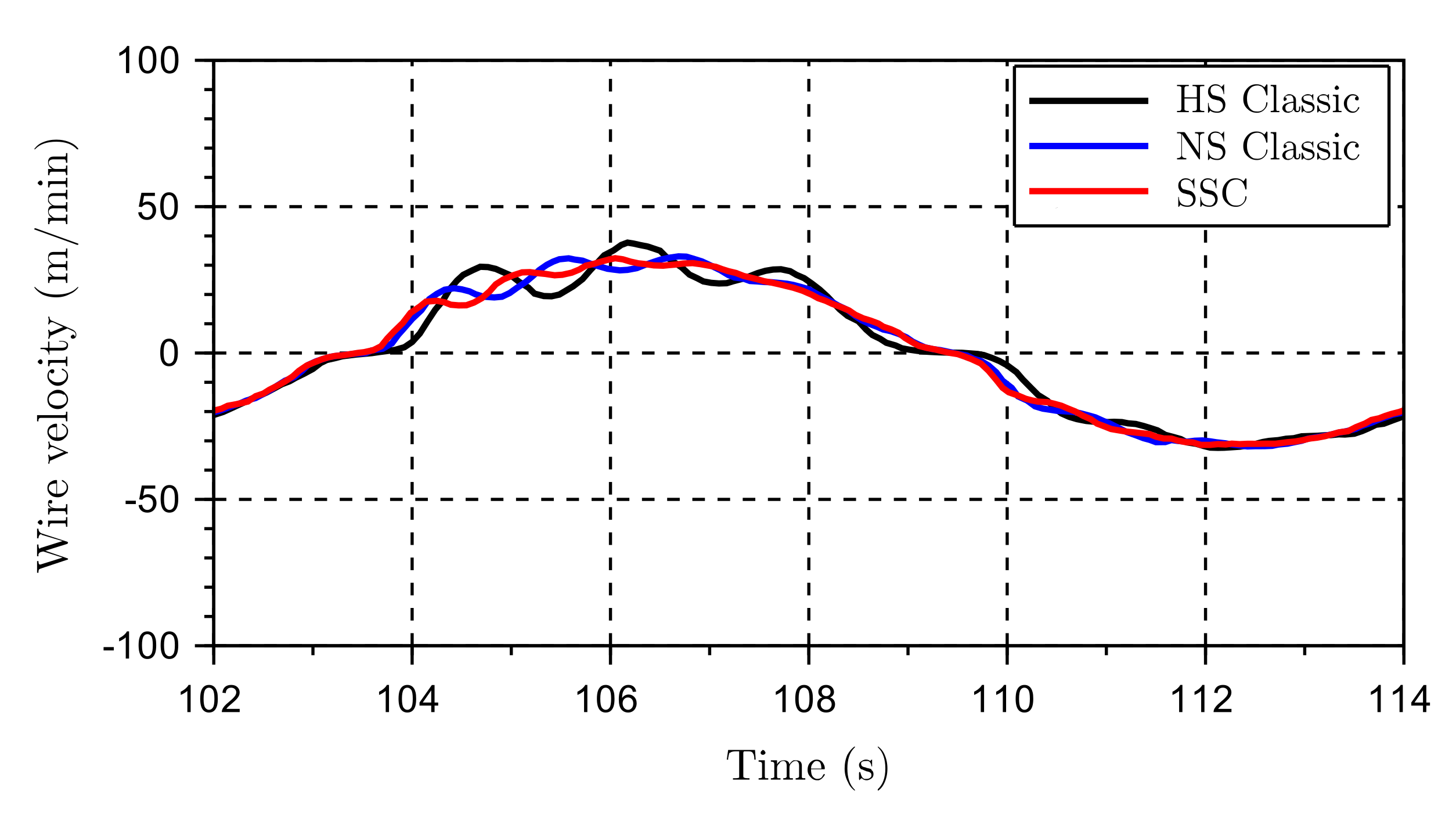
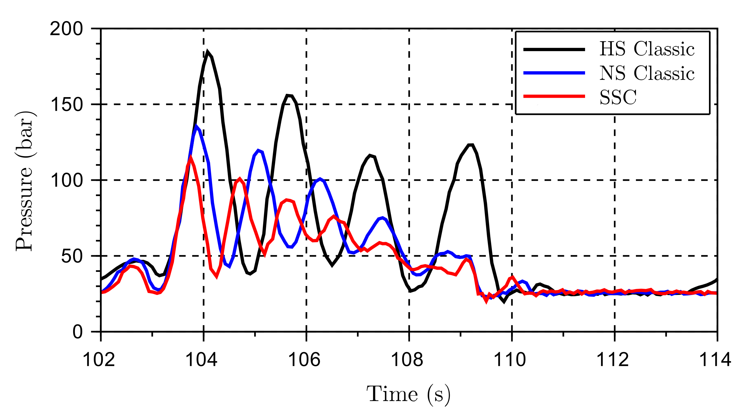
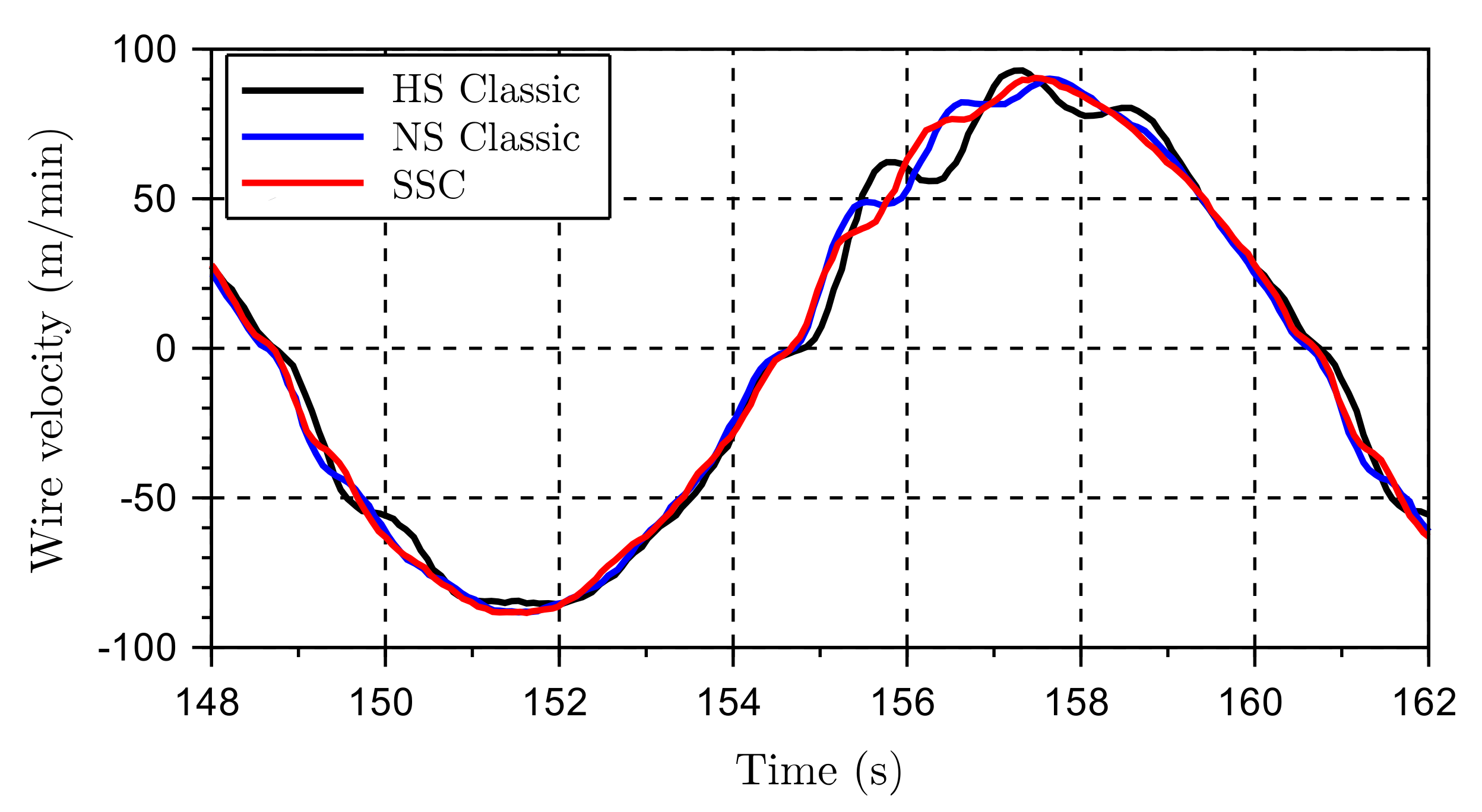
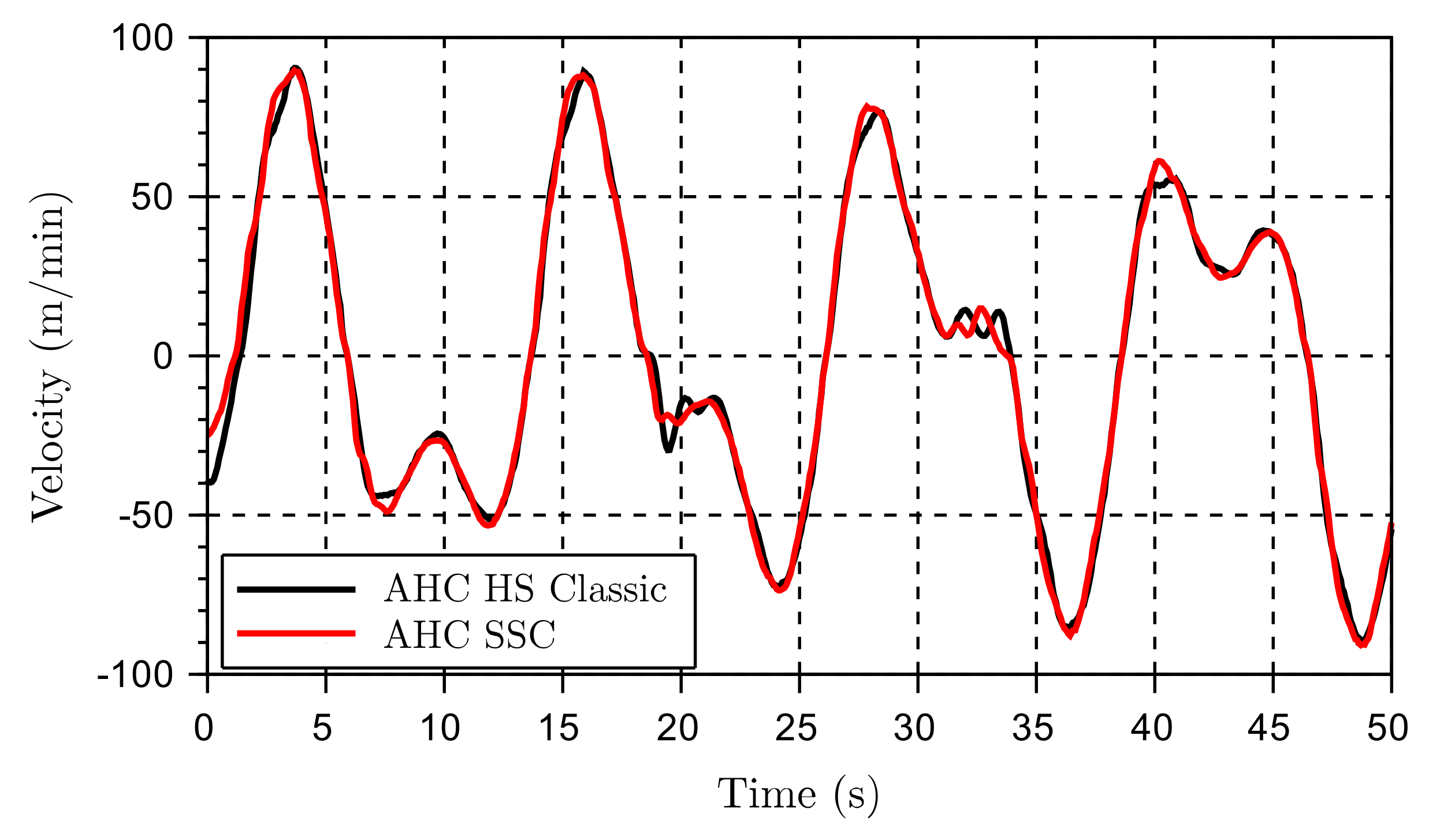
5.1.2. The Winch Performance

From earlier simulated results, by Moslått et al. [9], some of the significant benefits enabled by the new controller is a smoother winch control and lower pressures, especially at low-speed. Three different test scenarios are performed, including high and low wire velocities. Within these three test scenarios, a direct comparison between the classic control and the new SSC control is made. All scenarios were compared under the same conditions.
Scenario 1
The scenario 1 can be defined as a low-speed operation with a peak velocity around 30 m/min, see Figure 15, Figure 16, Figure 17 and Figure 18.
The VPFM methods are clearly more oscillatory in the velocity pattern (Figure 15), and more pronounced in the pressure pattern (Figure 16). The oscillations increase the control error that is kept to a minimum by the proposed method (Figure 17).
Scenario 2
In the second scenario the peak velocity is increased to the maximum capacity for the AHC normal speed (Figure 19).
The velocities are so high that the high speed (HS) mode would be the chosen option from a lift planner perspective. Comparing the proposed method (i.e., the AHC SSC) to the HS mode, the pressure peaks are now reduced by more than 120 bar (Figure 20), that is a significant achievement. Additionally, the control error remains within 10 cm compared to more than 20 cm for the HS mode (Figure 21). The normal speed mode is also performing adequately, but with higher pressures than the AHC SSC. When addressing the classic normal speed (NS), it is worth mentioning that this mode reaches its full capacity, while the AHC SSC still has 10% pump capacity left in addition to a potential motors’ displacement reduction of more than 20% (see Figure 22).
Scenario 3
Finally, a third scenario was tested (Figure 23, Figure 24, Figure 25 and Figure 26). The classic AHC HS controller is compared again with the AHC SSC controller.The wave pattern is made more complex with two overlying sine waves.
The purpose of this modification was exploring the systems’ performance under a scenario closer to a real-life operation. Typically, the vessel has at least two dominant frequency components. One frequency for large swells, often related to the pitch of the vessel, and another one with a bit smaller amplitude but higher frequency. The second frequency is, in many cases, related to the vessel roll. In this case, it was simulated as a 0.5 m amplitude with a 6 s period time on top of a 2 m amplitude with a 13 s period time.
The results from scenario 3 are in line with the previous ones and confirm that the AHC SSC has obvious advantages concerning controllability in the form of reduced oscillations for most conceivable working scenarios. The pressure levels are lowered (Figure 25), and the control error (Figure 26) is minimized.

5.2. Discussion of the Results

The results from the field tests are shown to be very much in line with the previously simulated results. From the empty hook tests at the quayside, the motors’ displacement control was confirmed to behave sufficiently well due to the acceptable response time. The positive effects of keeping a high displacement setting at low speed were confirmed since the classic controller lead to higher and more oscillatory pressures and winch motion, especially at low speeds shown in Figure 16 and Figure 17. This trend was also confirmed with the mapped results from simulations in Section 4. From the different maps, it is seen that the new controller expands the range of the AHC system in terms of both high velocity and high load scenarios. The performance has also been slightly improved, where normal speed mode is working close to its maximum velocity potential. Further, it is discovered that the peak pressures are reduced, especially for scenarios with high wire velocities. Additionally, the low-speed performance is improved (it was measured by the use of the settling time after a step command in the velocity reference). Concerning the crane tested in field, it was not possible to gain any extra speed compared to the classic HS controller due to gearbox speed limitations. Nevertheless, the AHC SSC controller enables higher load capacity and better winch performance. For the offshore testing, the results were similar, although it was not possible to compensate with higher velocities than 40m/min due to the weather conditions (40 m/min is below 50% of the rated winch capacity). The the results were still positive leading to reduced peak pressures and reduced oscillations. The classic HS mode was also tested offshore. The tests, not displayed in this paper, confirmed the same satisfactory behavior that was seen during the quayside tests.

6. Conclusions

The newly developed semi secondary control (SSC) method for offshore heave compensated winches has been investigated and compared to the current state-of-the-art approach with a fixed setting of the motors’ displacement. Firstly, it has been shown that the SSC leads to variations in the marginal stability because of the variations in the motor displacement, but, higher stability margins are achieved compared to the the classical control method at low speeds. Secondly, the increased window of operations expected from the SSC has been verified by comparing the peak-to-peak position error, peak pressure, and settling time for variations in both the payload and reference motion. Finally, the improved dynamic performance has been experimentally verified by means of full scale tests on a 250 ton crane.
In general, the active heave compensated (AHC) SSC system is shown to be the preferred control strategy. Based on the experimental and simulated results, the SSC show better performance in terms of control error and dynamics with significantly fewer oscillations and lower pressure levels (Figure 27). The fact that the new controller covers the whole operational area of both the AHC NS and the AHC HS, clearly suggests that the AHC SSC can succefully replace the two modes. Also, the AHC SSC controller allows higher velocities with more hook load than before and only requires one set of tuning parameters.

Author Contributions

Proposal: Conceptualization, G.-A.M.; methodology, G-A.M., D.P., and M.R.H.; software, G.-A.M.; validation, G.-A.M.; formal analysis, G.-A.M.; investigation, G.-A.M.; data curation, G.-A.M.; writing—original draft preparation, G.-A.M.; writing—review and editing, M.R.H. and D.P.; visualization, G.-A.M.; supervision, M.R.H. and D.P. All authors have read and agreed to the published version of the manuscript.

Funding

This research was funded by the research council of Norway and National Oilwell Varco Norway, grant number 263525. The APC was funded by the University of Agder.

Acknowledgments

Thanks to Anders Meisfjordskar for good conversations on the topic and to National Oilwell Varco Norway (NOVN) for dedicating resources to perform the full scale field tests. An excellent effort was given by Andreas Reppen at NOVN to prepare the crane-software, and the experimental field tests were assisted by Øystein Kolrud and Andreas Reppen.

Conflicts of Interest

The funder, National Oilwell Varco Norway, had a role in the design of the study; in the collection, analyses, and interpretation of data; in the writing of the manuscript, and in the decision to publish the results.

Abbreviations

α m Motor displacement feedback
α p Pump displacement feedback
ω m Rotational velocity of motor shaft
ω n m Natural eigenfrequency of motor displacement control
ω n p Natural eigenfrequency of pump displacement control
ζ m Damping ratio of motor displacement control
ζ p Damping ratio of pump displacement control
A m Laplace transform of α m
A m Laplace transformed α m
A p Laplace transform of α p
A p Laplace transformed α p
a t i p Crane tip acceleration
d D , m a x Maximum drum diameter
D m , m a x Maximum motor displacement
D m , m i n Minimum allowable motor displacement
ELaplace transform of e
eController error
i h D Transmission ratio between hydraulic motor shaft rotation and drum
J m e f f Total inertia on motor shaft
k 1 Proportional gain for crane tip velocity in feedforward controller
k 2 Proportional gain for crane tip acceleration in feedforward controller
K l e a k Laminar leakage factor
K p Proportional gain for feedback control error
k v g r e d Factor for motor displacement reduction
K w i r e Drum diameter factor
P A Laplace transform of p A
p A Pressure A side
p B Pressure B side
U f f Laplace transform of u f f
U f f Laplace transformed u f f
u f f Feedforward signal
U m Laplace transform of u m
U m Laplace transformed u m
u m Command signal for motor displacement control
U p Laplace transform of u p
u p Command signal for pump displacement control
U t h r Laplace transform of u t h r
u t h r Threshold value for when to start reducing motor displacement
V t i p Laplace transform of v t i p
V t i p Laplace transformed v t i p
v t i p Crane tip velocity
V w Laplace transform of v w
V w Laplace transformed v w
v w Wire velocity
W m Laplace transform of ω m
AHCActive heave compensation
AHC HSActive heave compensation, high-speed mode
AHC NSActive heave compensation, normal speed mode
FTCFault tolerant control
HSTHydrostatic transmission
MPCModel-based control
NOVNational Oilwell Varco
VPFMVariable pumps and fixed motors
VPVMVariable pumps and variable motors
SSCSemi secondary control
SWLSafe working load

References

  1. Woodacre, J.K.; Bauer, R.J.; Irani, R.A. A review of vertical motion heave compensation systems. Ocean Eng. 2015, 104, 140–154. [Google Scholar] [CrossRef]
  2. Feuser, A. Hydrostatic Drives with Control of the Secondary Unit; Mannesmann Rexroth GmbH: Lohr am Main, Germany, 1989; Volume 6. [Google Scholar]
  3. Palmgren, G.; Rydberg, K.E. Secondary Controlled Systems—Energy Aspects and Control Strategies. In Proceedings of the International Conference on Fluid Power, Tampere, Finland, 24–26 March 1987. [Google Scholar]
  4. Bosch Rexroth, A.G. Drive and Control Solutions for Marine Engineering: Reliable, Efficient, Durable; Rexroth Bosch B.V., Netherlands. Available online: https://dc-us.resource.bosch.com/media/us/products_13/product_groups_1/industrial_hydraulics_5/pdfs_4/R999001175_2015-1.pdf (accessed on 24 May 2020).
  5. Marien, M.; Wiig, K.E.; Ebbesen, M.K. Secondary Control of a Digital Hydraulic Motor for Winch Applications. Master’s Thesis, University of Agder, Kristiansand S, Norway, 2018. [Google Scholar]
  6. Padovani, D.; Ivantysynova, M. The Concept of Secondary Controlled Hydraulic Motors Applied to the Propulsion System of a Railway Machine. In Proceedings of the 14th Scandinavian International Conference on Fluid Power, Tampere, Finland, 20–22 May 2015. [Google Scholar]
  7. Padovani, D.; Ivantysynova, M. Simulation and Analysis of Non-Hybrid Displacement-Controlled Hydraulic Propulsion Systems Suitable for Railway Applications. In Proceedings of the ASME/BATH 2015 Symposium on Fluid Power and Motion Control, Chicago, IL, USA, 12–14 October 2015; p. 11. [Google Scholar] [CrossRef]
  8. Nikolaus, H. Antriebssystem mit hydrostatischer Kraftubertragung. Deutsches Patent 27,399,684, 6 September 1977. [Google Scholar]
  9. Moslått, G.A.; Padovani, D.; Hansen, M.R. A Control Algorithm for Active/Passive Hydraulic Winches Used in Active Heave Compensation. In Proceedings of the ASME/BATH 2019 Symposium on Fluid Power and Motion Control; American Society of Mechanical Engineers, Sarasota, FL, USA, 7–9 October; 2019; p. 11. [Google Scholar] [CrossRef]
  10. Kaddissi, C.; Kenne, J.P.; Saad, M. Identification and Real-Time Control of an Electrohydraulic Servo System Based on Nonlinear Backstepping. IEEE/ASME Trans. Mechatron. 2007, 12, 12–22. [Google Scholar] [CrossRef]
  11. Yao, J.; Jiao, Z.; Ma, D. Extended-state-observer-based output feedback nonlinear robust control of hydraulic systems with backstepping. IEEE Trans. Ind. Electron. 2014, 61, 6285–6293. [Google Scholar] [CrossRef]
  12. Mahulkar, V.; Adams, D.E.; Derriso, M. Adaptive fault tolerant control for hydraulic actuators. In Proceedings of the American Control Conference, American Automatic Control Council, Chicago, IL, USA, 1–3 July 2015; Volume 2015, pp. 2242–2247. [Google Scholar] [CrossRef]
  13. Yao, J.; Jiao, Z.; Ma, D.; Yan, L. High-accuracy tracking control of hydraulic rotary actuators with modeling uncertainties. IEEE/ASME Trans. Mechatron. 2014, 19, 633–641. [Google Scholar] [CrossRef]
  14. Yao, B.; Bu, F.; Reedy, J.; Chiu, G.T. Adaptive robust motion control of single-rod hydraulic actuators: Theory and experiments. IEEE/ASME Trans. Mechatron. 2000, 5, 79–91. [Google Scholar] [CrossRef]
  15. Yao, J.; Deng, W.; Jiao, Z. Adaptive control of hydraulic actuators with LuGre model-based friction compensation. IEEE Trans. Ind. Electron. 2015, 62, 6469–6477. [Google Scholar] [CrossRef]
  16. Yao, J.; Jiao, Z.; Ma, D. A Practical Nonlinear Adaptive Control of Hydraulic Servomechanisms with Periodic-Like Disturbances. IEEE/ASME Trans. Mechatron. 2015, 20, 2752–2760. [Google Scholar] [CrossRef]
  17. Do, H.T.; Ahn, K.K. Velocity control of a secondary controlled closed-loop hydrostatic transmission system using an adaptive fuzzy sliding mode controller. J. Mech. Sci. Technol. 2013, 27, 875–884. [Google Scholar] [CrossRef]
  18. Meller, M.; Kogan, B.; Bryant, M.; Garcia, E. Model-based feedforward and cascade control of hydraulic McKibben muscles. Sens. Actuators A Phys. 2018, 275, 88–98. [Google Scholar] [CrossRef]
  19. Chatzakos, P.; Papadopoulos, E. On model-based control of hydraulic actuators. Proc. RAAD 2003, 3, 7–10. [Google Scholar]
  20. Rezayi, S.; Arbabtafti, M. A New Model-Based Control Structure for Position Tracking in an Electro-Hydraulic Servo System with Acceleration Constraint. J. Dyn. Syst. Meas. Control 2017, 139. [Google Scholar] [CrossRef]
  21. Guan, C.; Pan, S. Adaptive sliding mode control of electro-hydraulic system with nonlinear unknown parameters. Control Eng. Pract. 2008, 16, 1275–1284. [Google Scholar] [CrossRef]
  22. Zheng, S.; Wang, X.; Lu, Y.; Wang, Y. The sliding mode control for speed system of the variable displacement motor at the constant pressure network. In Proceedings of the 2013 International Conference on Intelligent Control and Information Processing, ICICIP 2013, Beijing, China, 9–11 June 2013; pp. 499–503. [Google Scholar] [CrossRef]
  23. Liu, S.; Guo, Q.; Zhao, W. Research on active heave compensation for offshore crane. In Proceedings of the 26th Chinese Control and Decision Conference, CCDC 2014, Changsha, China, 31 May–2 June 2014; pp. 1768–1772. [Google Scholar] [CrossRef]
  24. Shi, M.; Guo, S.; Jiang, L.; Huang, Z. Active-Passive Combined Control System in Crane Type for Heave Compensation. IEEE Access 2019, 7, 159960–159970. [Google Scholar] [CrossRef]
  25. Michel, A.; Kemmetmüller, W.; Kugi, A. Modeling and control of an active heave compensation system for offshore cranes. At-Automatisierungstechnik 2012, 60, 8–15. [Google Scholar] [CrossRef]
  26. Sanders, R. Modelling and Simulation of Traditional Hydraulic Heave Compensation Systems; Technical Report; University of Twente, Faculty of Engineering Technology: Enschede, The Netherlands, 2016. [Google Scholar]
  27. Wu, J.; Wu, D. Integrated design of an active heave compensation crane with hydrostatic secondary control. In Proceedings of the OCEANS 2018 MTS/IEEE Charleston, OCEAN 2018, Charleston, SC, USA, 22–25 October 2018; pp. 1–7. [Google Scholar] [CrossRef]
  28. Donkov, V.; Andersen, T.; Ebbesen, M.K.; Linjama, M.; Paloniitty, M. Investigation of the fault tolerance of digital hydraulic cylinders. In Proceedings of the 16th Scandinavian International Conference on Fluid Power, Tampere, Finland, 22–24 May 2019. [Google Scholar]
  29. Dijoux, E.; Steiner, N.Y.; Benne, M.; Péra, M.C.; Pérez, B.G. A review of fault tolerant control strategies applied to proton exchange membrane fuel cell systems. J. Power Sources 2017, 359, 119–133. [Google Scholar] [CrossRef] [Green Version]
  30. Küchler, S.; Mahl, T.; Neupert, J.; Schneider, K.; Sawodny, O. Active control for an offshore crane using prediction of the vessels motion. IEEE/ASME Trans. Mechatron. 2011, 16, 297–309. [Google Scholar] [CrossRef]
  31. Kusters, J.G.; Cockrell, K.L.; Connell, B.S.; Rudzinsky, J.P.; Vinciullo, V.J. FutureWaves™: A real-time Ship Motion Forecasting system employing advanced wave-sensing radar. In Proceedings of the OCEANS 2016 MTS/IEEE Monterey, OCE 2016, Monterey, CA, USA, 19–23 September 2016; pp. 1–9. [Google Scholar] [CrossRef]
  32. Del Re, L.; Goransson, A.; Astolfi, A. Enhancing Hydrostatic Gear Efficiency Through Nonlinear Optimal Control Strategies. J. Dyn. Syst. Meas. Control 1996, 118, 727–732. [Google Scholar] [CrossRef]
Figure 1. Simplified schematic for a hydraulic active/passive winch system.
Energies 13 02671 g001
Figure 2. The new control structure.
Energies 13 02671 g002
Figure 3. Motor displacement control due to u f f .
Energies 13 02671 g003
Figure 4. Steady-state motors’ and pumps’ displacement setting ( α m and α p ).
Energies 13 02671 g004
Figure 5. Variation of the motor displacement with all other system parameters fixed.
Energies 13 02671 g005
Figure 6. Velocity reference (the first 10 s are neglected due to the model initialization).
Energies 13 02671 g006
Figure 7. Maximum peak-to-peak control error (PPCE) during the test sequence: (a) Classic; (b) SSC.
Energies 13 02671 g007
Figure 8. Maximum peak pressure during test sequence: (a) Classic; (b) SSC.
Energies 13 02671 g008
Figure 9. Description of the test for the settling time.
Energies 13 02671 g009
Figure 10. Settling time within 2% after a 5 m/min step increase of the reference velocity: (a) Classic; (b) SSC.
Energies 13 02671 g010
Figure 11. Motors’ displacement for the results shown in Figure 10: (a) Classic; (b) SSC.
Energies 13 02671 g011
Figure 12. A 250t AHC crane from National Oilwell Varco placed on a vessel.
Energies 13 02671 g012
Figure 13. Response of the motors to a displacement variation.
Energies 13 02671 g013
Figure 14. Simulated sinusoidal motion with 12 s period and 6 s period. The motors’ displacement controller runs in open-loop.
Energies 13 02671 g014
Figure 15. Wire velocities for scenario 1.
Energies 13 02671 g015
Figure 16. Pressure levels on the A-side of the active system for scenario 1.
Energies 13 02671 g016
Figure 17. Control error for scenario 1.
Energies 13 02671 g017
Figure 18. Pump and motor displacement settings for scenario 1 (0% for the motor means maximum displacement).
Energies 13 02671 g018
Figure 19. Wire velocities for scenario 2.
Energies 13 02671 g019
Figure 20. Pressure levels on the A-side of the active system for scenario 2.
Energies 13 02671 g020
Figure 21. Control error for scenario 2.
Energies 13 02671 g021
Figure 22. Pump and motor displacement settings for scenario 2 (0% for the motor means maximum displacement).
Energies 13 02671 g022
Figure 23. Crane’s tip position for scenario 3.
Energies 13 02671 g023
Figure 24. Wire velocities for scenario 3.
Energies 13 02671 g024
Figure 25. Pressure levels on the A-side of the active system for scenario 3.
Energies 13 02671 g025
Figure 26. Control error for scenario 3.
Energies 13 02671 g026
Figure 27. Significant findings from comparison between the classic controller and the SSC.
Energies 13 02671 g027
Table 1. Main component data.
DescriptionTotal Size
Active motors1075 cm 3 /rev
Passive motors3440 cm 3 /rev
Active pumps1355 cm 3 /rev
Passive pumps1210 cm 3 /rev
Gearbox ratio35.4
Pinion ring-gear ratio14.17
Drum diameter (without wire)2.8 m
Drum width1.9 m
Wire diameter96 mm
Table 2. Parameters.
d D , m a x 5.1 m J m e f f 4.1 kg/m 2 β 17,500 bar
V A 80 l i h D 501.6 ζ p 0.9
D m , m a x 1075 cm 3 /rev D m , m i n 645 cm 3 /rev ω n p 31 rad/s
K p 0.16 m 1 U t h r 0.6 ζ m 1
K 1 0.68 s/m B v 2 . 1 Nm · s rad ω n m 5 rad/s
K l e a k 0 . 4 l min / bar ω p 1800 rev/min K w i r e 1

