Article

Numerical and Circuit Modeling of the Low-Power Periodic WPT Systems

by
Adam Steckiewicz
*,
Jacek Maciej Stankiewicz
and
Agnieszka Choroszucho
Faculty of Electrical Engineering, Bialystok University of Technology, Wiejska 45D, 15-351 Bialystok, Poland
*
Author to whom correspondence should be addressed.
Energies 2020, 13(10), 2651; https://doi.org/10.3390/en13102651
Submission received: 5 April 2020 / Revised: 18 May 2020 / Accepted: 19 May 2020 / Published: 22 May 2020
(This article belongs to the Special Issue Modelling of Wireless Power Transfer)

Abstract

:
This article presents a method for analysis of the low-power periodic Wireless Power Transfer (WPT) system, using field and circuit models. A three-dimensional numerical model of multi-segment charging system, with periodic boundary conditions and current sheet approximation was solved by using the finite element method (FEM) and discussed. An equivalent circuit model of periodic WPT system was proposed, and required lumped parameters were obtained, utilizing analytical formulae. Mathematical formulations were complemented by analysis of some geometrical variants, where transmitting and receiving coils with different sizes and numbers of turns were considered. The results indicated that the proposed circuit model was able to achieve similar accuracy as the numerical model. However, the complexity of model and analysis were significantly reduced.

Graphical Abstract

1. Introduction

In the present days, we have observed a growing number of devices operating due to wireless power transfer (WPT) technology [1], which became more available in extensive scattered grids of many interdependent sources and loads [2]. Current trends in wireless charging of electric vehicles [3,4] and modern electronics [1,5,6] have led to the development of the inductive power transfer (IPT) concept. Among other things, an increasing number of mobile devices processing huge amounts of data [7,8] is directly connected with their computing power and number of sensors. Nowadays, WPT is considered to be an alternative method of charging wireless devices, where a pair of coils [7,9] (accompanied with additional intermediate coils [10,11]) or an array of coils [12,13,14] is utilized. Multi-coil systems operate at high frequencies (f ≥ 1 MHz) [13,15], and in some cases, power transfer is assisted by using metamaterial structures [14]. For low frequencies (f < 1 MHz), an array of coils as domino form resonators [16] and linear resonator arrays [17,18] are considered, where in intermediate space between transmitter and receiver, energy transfer is assisted by using several resonators. However, a detailed analysis was performed for a series configuration of resonators, while parallel-series topology of planar coils, acting as group of energy transmitters and receivers, are still not fully developed. Wireless charging is also considered in the systems of beacons [19] in hard-to-reach places, medical implants in human body [20], and smart buildings with sensors inside rooftops and walls [21].
Energy supply or charging of many devices located in close range to each other may be simplified by using WPT systems as a grid of periodically arranged coils which forms surfaces for transmitting or receiving the energy. This solution increases the density of transferred power, and also simultaneous energy supply (using single power source) for many devices is possible. Potential applications of this system are mainly focused on the simultaneous charging of an array of sensors (embedded in, e.g., walls or floors) and sets of implantable electronic devices placed inside the body [22]. From the point of view of high-power applications, proposed models of periodic WPT surfaces may be utilized as an analysis method when charging vehicles on large parking spaces is considered.
This article presents a wireless power transfer system with periodically arranged planar coils. The main purpose of this work is to introduce and study numerical and circuit model, which can be applied to analyze power transfer conditions in discussed systems. Both approaches reduce size and complexity of typically utilized numerical and circuit models. The proposed unit cell analysis with periodic boundary conditions does not require a full 3D model with many coils [23] in which the number of degrees of freedom is significant. A simplified model in the form of a well-known T-type equivalent circuit is an alternative for more extensive matrix formulation [11,16,17], where a large coefficient matrix with lumped parameters has to be known. Both models make it possible to evaluate the influence of the coil structure on power transfer. Adjusting the geometrical parameters gives an ability to obtain high efficiency of the power transfer to multiple loads. A numerical analysis of the time-harmonic magnetic field in a 3D model of the system is characterized, and, on this basis, the efficiency and power transfer conditions are specified. The simplified circuit model is proposed, and the required lumped parameters are calculated by using analytical formulae. The computational results in the frequency domain of the exemplary periodic WPT systems, performed in numerical software, are compared with the results obtained from an equivalent circuit. The authors analyzed the influence of geometrical parameters (coil radius, number of turns, and distance between coils) on power transfer efficiency, as well as transmitter and receiver currents.

2. Materials and Methods

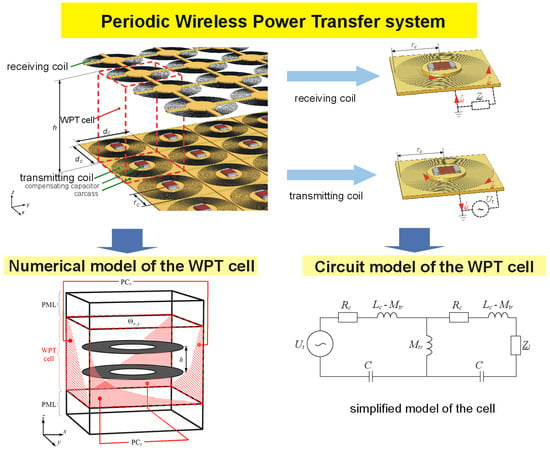
2.1. Periodic Wireless Power Transfer System

Among typical WPT devices consisting of several coils, systems with many inductive elements may also be considered. A pair of transmitting (TR) and receiving (RE) circular inductors at the distance, h, possessing identical radius, rc, and number of turns, nc, are the fundamental parts of the WPT cell with outer dimensions dc × dc (Figure 1). Windings are wound around a dielectric carcass with additional compensating capacitors. The periodic distribution of WPT cells (Figure 1) leads to transmitting and receiving surfaces where the energy transmission occurs. The transmitting surface consists of TR coils connected parallel to the sinusoidal voltage source (RMS value Ut), while RE coils are connected with individual loads, Zl.
Proposed configuration enhances the density of transferred power in an area between transmitting and receiving surfaces. Furthermore, the energy supply conditions can be adjusted. For example, the simultaneous power transfer to many independent devices is possible, where each WPT cell is directly connected with individual energy storage. Another possibility is to connect parallel every RE coil to a single common energy receiver. The series connection of coils and intermediary parallel-series configuration are possible. An analysis of the periodic system can be reduced to the two-dimensional plane, xy (Figure 2), representing a set of TR or RE coils. The considered cell, Θx+a,y+b, is an element of an array with identical inductors, where a is the number of columns and b is the number of rows in a grid; a, bZ, and Z are the set of integers. Adjacent coils (e.g., Θx,y+1 or Θx−1,y) of element Θx,y are separated by the distance, dc. Magnetic coupling, which occurs between coil Θx,y and the others, is undesirable and affects power transfer efficiency between transmitting and receiving surfaces. Due to the small distance between coils (dc ≈ 2rc), magnetic coupling phenomena must be included in models.

2.2. Modeling Approach

The analysis of a periodic wireless charging system may be performed by using numerical methods or experimental research of some prototypes. An application of simulation software gives an ability to create a numerical model of the system and to find a distribution of magnetic field. However, a three-dimensional model is required, as well as complex boundary conditions. Effectiveness and accuracy of the obtained solution arise from model size (number of degrees of freedom, NDOF). A greater number of degrees of freedom results in greater accuracy of solution but also leads to a longer calculation time. On the other hand, during the experimental research, it is necessary to build several prototypes with many coils and specified geometry. While it is possible to examine the impact of electrical parameters (e.g., current frequency and load impedance) on wireless power transfer, the potential identification of geometrical parameters (e.g., coil radius and number of turns) is limited.
At the design stage and initial analysis of periodic WPT charging system and its properties (e.g., efficiency, power losses, and load power), mathematical models are sufficient. Hence, two possible approaches were characterized:
  • Numerical model of periodic WPT system, with necessary simplifications and boundary conditions.
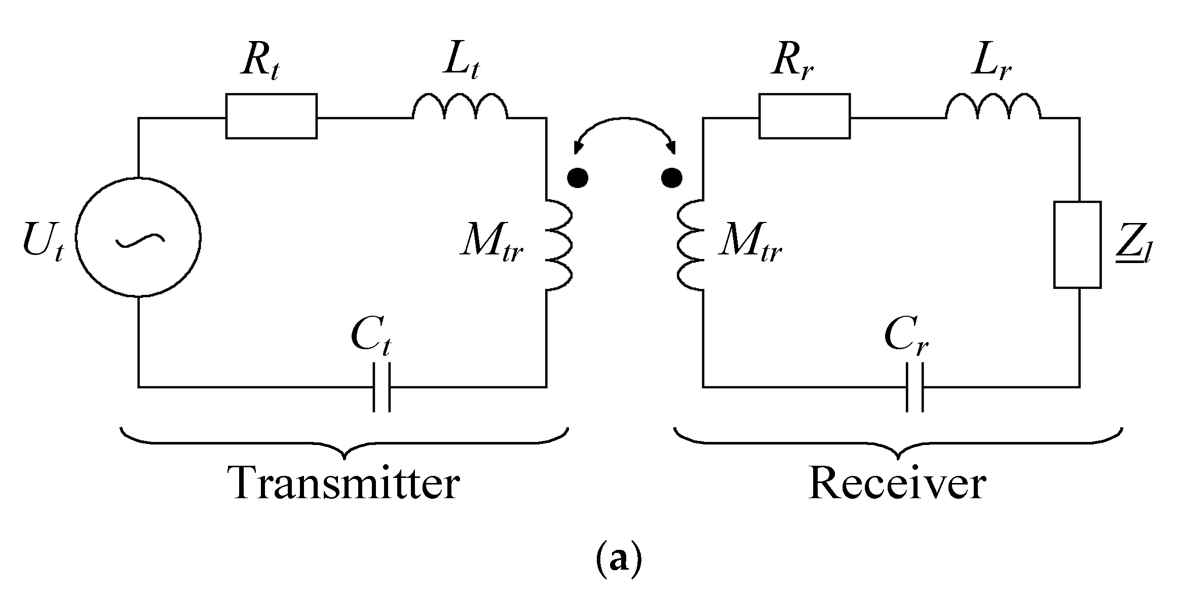
  • Circuit model as an alternative for numerical model.
The usage of electrical circuit helps to avoid the numerical analysis and building a series of prototypes subjected to experiments.

2.3. Numerical Model
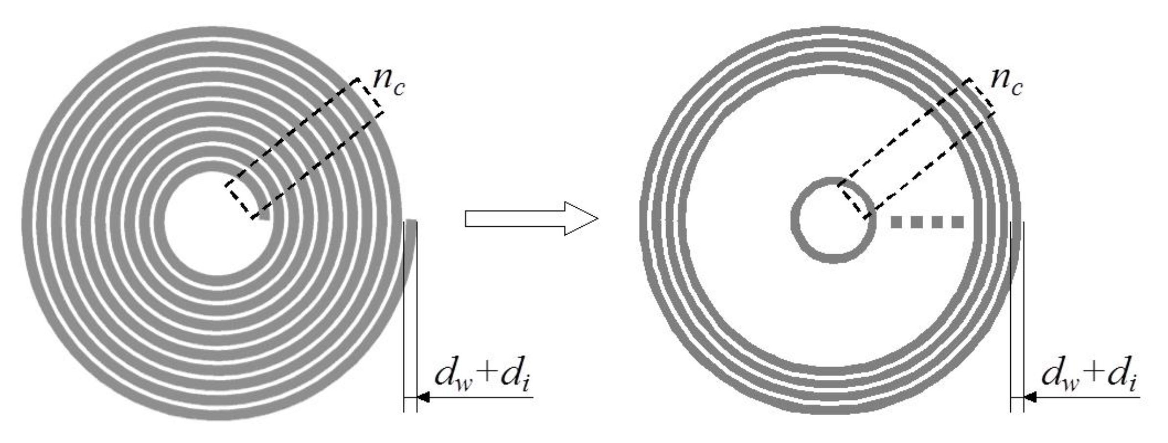
A numerical analysis of energy transfer in the system combined with many WPT cells requires taking into account many details of the model, such as the following:
  • Coil geometry,
  • Winding structure, number of WPT cells,
  • Electrical elements (e.g., compensating capacitors, loads) connected to coils.
Planar spiral coils were wound of several dozens of turns, made of ultra-thin wires with diameter dw. In order to reduce NDOF, current sheet approximation [24,25,26] was applied, which replaces the multi-turn coil with a homogeneous structure (Figure 3). Current sheet is a model for a group of wires wound together around a specified carcass, but still insulated from each other by an electrical insulator of a thickness di. The current flows in the direction of wires (xy plane), while current densities in other directions are omitted. To correctly apply this method of approximation, one may make the following assumptions:
n c 10 ,
d w < δ ,
d i < < d w ,
where nc is the number of turns, δ is the penetration depth, and di is the wire insulation thickness. Without current sheet approximation, Assumptions (1a) and (1c) impose the necessity to include every turn. As a consequence, this increases NDOF, which makes the numerical model difficult to solve using typical computational units.
Compensating capacitor can be modeled as an element with lumped capacity, C. Additionally, it is possible to omit a carcass if it is made of dielectric and non-magnetic material (μ = μ0). A voltage source with RMS value Ut and frequency f is connected to each coil and current It flows through transmitter. Receiving coil, connected with a linear load, Zl, carry induced current Ir.
In order to simulate the periodic WPT system (Figure 1), all the cells forming transmitting and receiving surfaces have to be taken into account. However, for the system with many WPT cells (a, b >> 3), another simplification is possible. Assuming a, b→±∞ periodic boundary conditions (PC) both in x and y direction may be applied. Then, wireless charging system will be simplified to a single cell Θx,y, filled with air and containing a pair of transmitting and receiving coils (Figure 4). Periodic boundary conditions are applied on the left and right (PCx), as well as the front and back (PCy) boundaries, in order to project an infinite array of WPT cells. A perfectly matched layer (PML) is put at the top and bottom of the model, to imitate a dielectric background. The model is complemented by application of simplified multi-turn spiral coils with an attached part of the electrical circuit, as shown in Figure 3b,d.
The energy transport problem in the presented system (Figure 4) can be solved by using magnetic vector potential A = [Ax Ay Az] and formulation of magnetic field phenomena in frequency domain, using the Helmholtz equation:
× ( μ 0 1 × A ) j ω σ A = J e x t ,
where μ0 is the permeability of air (H/m), ω is the angular frequency (rad/s), σ is the electrical conductivity (S/m), and Jext is the external current density (A/m2). Periodic boundary conditions on four external surfaces were defined as a magnetic insulation:
n × A = 0 ,
where n = [1x 1y 1z] is a surface normal vector. Voltage supply (Ut) has direct impact on Jext, and when combined with Equation (3), it enables us to solve Equation (2) by using numerical methods, e.g., finite element method (FEM). Then, the volume distribution of vector potential A(x,y,z) can be found. The capacity of the compensating capacitor may be defined from the parametric analysis of the system for different C. When Im[It] ≈ 0 one may assume, that the resonant state was reached and adjusted value of C is a required capacity.

2.4. Circuit Model

The formulation and solution of a numerical model of a periodic WPT system is a multi-task problem, requiring advanced numerical methods. Despite an ability of performing simulation on typical computational units, it is desirable to propose a simpler model that still will be able to ensure similar analysis, but faster modeling and less-complex calculations. As an alternative, we proposed a circuit model (Figure 5) combining two-port network with analytical formulae for calculating lumped parameters. Similar to the numerical model, the infinite periodic grid would be simplified to analysis of a single WPT cell. The solution of the circuit model in the frequency domain can be performed by using methods of circuit analysis; however, the main issue is to determine the values of several lumped parameters. It is necessary to take into account the impact of adjacent cells on inductances Lt and Lr of TR coil and RE coil, as well as their mutual inductance, Mtr.
Resistance of a coil may be found by replacing spiral structure of windings, using concentering circles possessing identical widths, dw + di (Figure 6). Starting from the outer edge, the mean length of each circle is described by the following:
l n = π [ 2 r c ( 2 n 1 ) ( d w + d i ) ] ,
Hence, total length of all circles is defined as follows:
l c = n = 1 n c l n = π n c [ 2 r c n c ( d w + d i ) ] .
By substituting Equation (5) to the formula determining resistance of a conductor with constant cross section, resistance of an inductor can be found:
R c = l c σ π ( d w 2 ) 2 = 4 n c [ 2 r c n c ( d w + d i ) ] σ d w 2 .
If coils (TR and RE) are identical and the considered frequency bandwidth condition (1b) is met, calculated resistances Rt = Rr = Rc will not be dependent of frequency.
Self-inductance of a spiral planar coil can be calculated by using the following formula [27]:
L s e l f = 1 2 c 1 μ 0 d a v g n c 2 [ ln ( c 2 ρ ) + c 3 ρ + c 4 ρ 2 ] ,
where davg is a mean diameter
d a v g = 2 r c ( d w + d i ) n c ,
and ρ is a fill factor
ρ = ( d w + d i ) n c 2 r c ( d w + d i ) n c ,
while coefficients c1, c2, c3, and c4 are depending on geometry (shape) of a coil [27]. For identical TR and RE coils calculated inductances are equal, Lt = Lr = Lc (Figure 5).
In the periodic grid, coils are adjacent; hence, it is necessary to include magnetic coupling between them. Mutual inductance Mperiod, which came directly from periodic distribution of coils arranged on the surface xy, is a sum of all mutual inductances [28,29]:
M p e r i o d = a b ( M x + a , y + b ) M x , y ,
where Mx+a,y+b is the mutual inductance between coil at coordinate (x,y) and coil at a-th column and b-th row; Mx,y = Lself is self-inductance. The following assumptions are then taken into account:
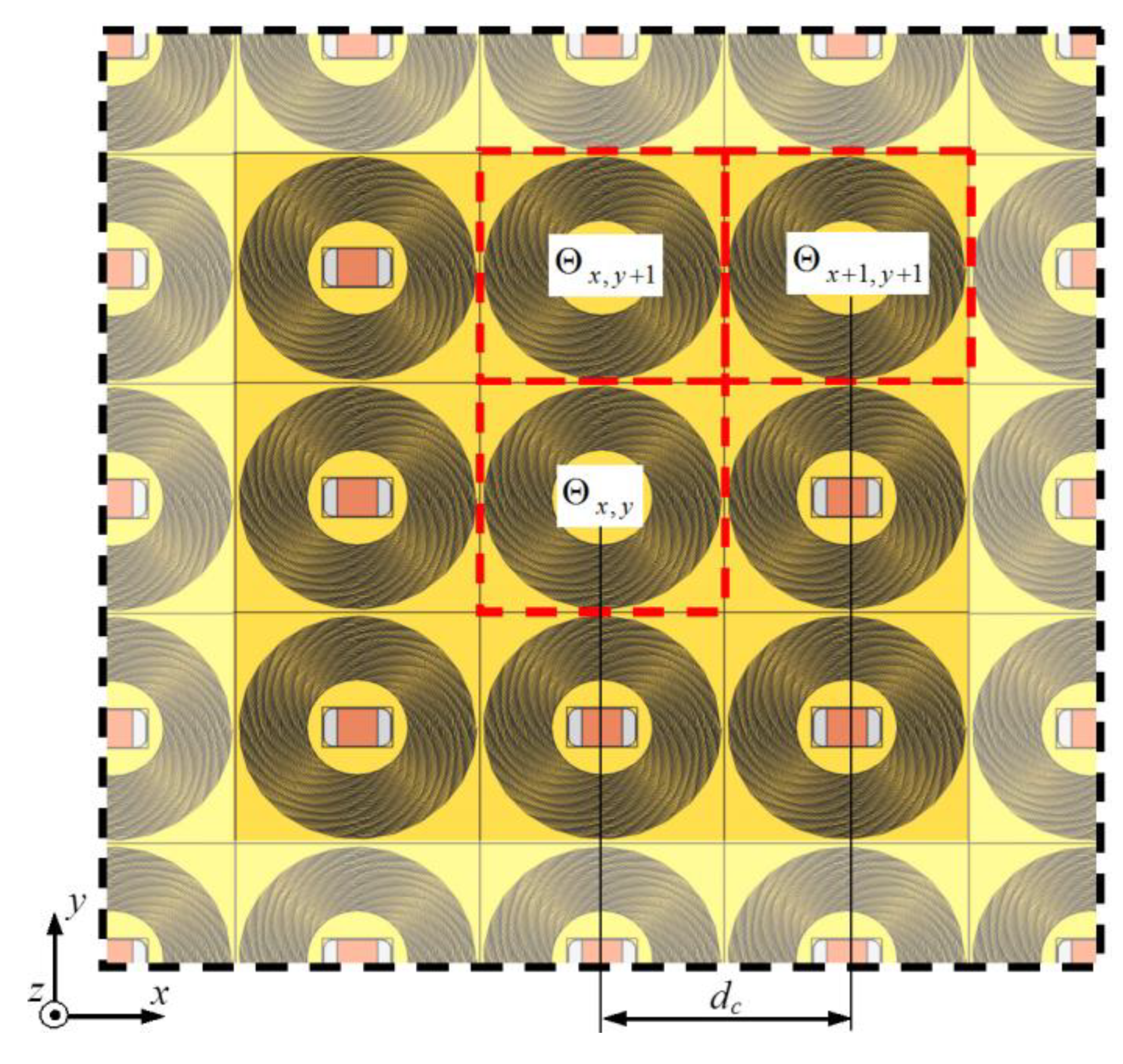
  • Only coupling between adjacent coils is considered (|a|max = |b|max = 1),
  • The system is periodic and symmetrical (Mx+a,y+b = Mx−a,y−b),
  • Mutual inductances of coils adjacent to Θx,y are assumed to be approximately equal (Mx+a,yMx,y+bMx+a,y+b),
By taking into account the above assumptions, Equation (10) can be simplified as follows:
M p e r i o d = 8 M x , y + 1 ,
where Mx,y+1 is the mutual inductance between coil at coordinate (x,y) and an edge adjacent coil (Figure 2). For calculation of Mx,y+1, the formula introduced by Siu, Su, and Lai [30] is suitable:
M x , y + 1 = μ 0 g 2 4 π Φ i Φ o Φ i Φ o [ ( 1 + φ 1 φ 2 ) cos ( φ 2 φ 1 ) ( φ 2 φ 1 ) sin ( φ 2 φ 1 ) ] d φ 1 d φ 2 ( d c + g φ 2 cos φ 2 g φ 1 cos φ 1 ) 2 + ( g φ 2 sin φ 2 g φ 1 sin φ 1 ) 2 ,
where g = (dw + di)/(2π), Φi = [rc−(dw + di)nc]/g, Φo = rc/g. In the literature, no analytical solution for Equation (12) was found; however, it is possible to find it by using numerical integration. After applying the rectangle rule formula, Equation (12) takes the following form:
M x , y + 1 = μ 0 g Φ K 4 π k 2 = 1 K k 1 = 1 K ( 1 + k 1 k 2 Φ K 2 ) cos ( k 2 Φ K k 1 Φ K ) ( k 2 Φ K k 1 Φ K ) sin ( k 2 Φ K k 1 Φ K ) ( d c g Φ K + k 2 cos k 2 Φ K k 1 cos k 1 Φ K ) 2 + ( k 2 sin k 2 Φ K k 1 sin k 1 Φ K ) 2 ,
where ΦK = (Φo−Φi)/K is an integration step, while K is assumed number of integration subintervals, Krc/g and KN.
Horizontal periodicity affects the magnetic field of an arbitrary coil, where the opposite magnetic field of neighboring inductors reduces total magnetic energy associated with this coil. As a consequence, its effective inductance, Lc, will be less than self-inductance, Lself. For the total mutual inductance of Equation (11), the effective inductance of the considered coil in segment Θx,y will be defined as follows:
L c = L s e l f + M p e r i o d = L s e l f + 8 M x , y + 1 ,
In the next step, after calculations of self-inductance, Lself, using Equations (7)–(9) and total mutual inductance in periodic grid Mx,y+1 from Equation (13), both quantities are substituted to Equation (14), in order to find effective inductance Lc. On the basis of a series resonant and known value of Lc, it is possible to find the compensating capacity, C, at a specified frequency.
C ( f ) = 1 4 π 2 f 2 L c = 1 4 π 2 f 2 ( L s e l f + M p e r i o d ) = 1 4 π 2 f 2 ( L s e l f + 8 M x , y + 1 ) ,
where Ct = Cr = C( f ), if it was assumed that TR and RE coils are identical.
Mutual inductance Mtr may be presented in the following form:
M t r = k p M z ,
where mutual inductance Mz between transmitter and receiver is calculated from the following [30]:
M z = μ 0 g 2 4 π Φ i Φ o Φ i Φ o [ ( 1 + φ 1 φ 2 ) cos ( φ 2 φ 1 ) ( φ 2 φ 1 ) sin ( φ 2 φ 1 ) ] d φ 1 d φ 2 h 2 + g 2 φ 1 2 + g 2 φ 2 2 2 g 2 φ 1 φ 2 cos ( φ 2 φ 1 ) ,
and after an application of rectangle rule, Equation (17) has the following form:
M z = μ 0 g 2 Φ K 2 4 π k 2 = 1 K k 1 = 1 K ( 1 + k 1 k 2 Φ K 2 ) cos ( k 2 Φ K k 1 Φ K ) ( k 2 Φ K k 1 Φ K ) sin ( k 2 Φ K k 1 Φ K ) h 2 + g 2 ( k 1 Φ K ) 2 + g 2 ( k 2 Φ K ) 2 2 g 2 k 1 k 2 Φ K 2 cos ( k 2 Φ K k 1 Φ K ) .
Periodic coupling coefficient, kp, results from physical phenomena in which the magnetic field of all coils in the system affects mutual inductance, Mz. As a result, Mtr < Mz, which means that, for periodic WPT, Mtr between TR and RE is reduced by some factor kp. In other words, the kp is related to magnetic couplings between coils adjacent to Θx,y (reducing Lself by Mperiod), as well as to power transfer between neighboring WPT cells. If numerical or experimental data for particular systems are known, it is possible to find kp by comparing these data with those obtained from an equivalent circuit.
A different way is analytical derivation of coupling coefficient, which is a very complex task. Therefore, an empirical formula was proposed as a simplification for presented small-scale systems:
k p = exp ( λ h / r c ) ,
where λ is an approximation function coefficient. Based on a set of numerical results (Figure 7) for different h/rc, the authors have derived λ = 1.2252 as an optimal value for exponential approximation function (19). Then, substituting parameters calculated from Equations (18) and (19) to (16), it is possible to find mutual inductance, Mtr, for the WPT cell, which is applicable at, for example, the early design stage.

3. Results and Discussion

3.1. Analyzed Models

The numerical field model took into account the electromagnetic phenomena and geometrical structure of the WPT cell; hence, it was a reference for the simplified circuit model. On the basis of obtained results for several exemplary periodic WTP system, the authors have verified the validity of its electrical model by comparing absolute current of TR (It) and RE (Ir) coils, as well as energy transfer efficiency, η. Since passive load, Zl, was considered, its active power was calculated by using the following formula:
P l = Z l I r 2 .
Because of the resonant state obtained after an application of the compensating capacitor, the imaginary part of the transmitter current was negligible (Im[It] ≈ 0); hence, voltage source produced only active power.
P s = U t I t .
Finally, using Equations (20) and (21), we found the power transfer efficiency:
η = P l P s 100 % .
In the further part of this section about the characteristics of It, Ir, and η with the label FM (field model) were related to numerical model and with the label EC to electrical circuit.
We subjected to analysis discussed unit cell Θx,y, where we assumed that the system consists of an infinite number of WPT cells. Every cell consisted of a pair of identical coaxial coils arranged at a distance, h, and wounded using wire with a diameter of dw = 150 µm, insulation thickness di = 1 µm, and conductivity σ = 5.6·107 S/m. When Lself was calculated by using Equation (7), we assumed c1 = 1, c2 = 2.5, c3 = 0, and c4 = 0.2. Voltage supply with RMS value Ut = 5 V and frequency from fmin = 0.1 MHz to fmax = 1 MHz was attached to the TR coil. Passive load Zl = 50 Ω was connected with the RE coil. We analyzed small- (rc = 5 mm) and large-size coils (rc = 20 mm) with a different number of turns, nc, distance, h (Table 1), and constant separation between neighboring cells, dc = 2.25rc. The numerical model (Figure 4) created in Comsol Multiphysics software was solved by FEM. We utilized built-in multi-turn coils’ approximation and partial electrical circuit combined with a 3D model. Lumped parameters of electrical circuit of Figure 5b (Table 2) were found by using Equations (6), (7), (13), (15), (18), and (19). Transmitter and receiver currents, as well as power transfer efficiency (Equation (22)), were calculated for both models, within frequency range fmin ÷ fmax.

3.2. Model Comparison and Electrical Parameters

At the beginning, computations of small-size coils (rc = 5 mm) were performed. The results from numerical and circuit model for nc = 10 (Figure 8) were in a good agreement, since characteristics for different distances, h, and frequencies overlapped. However, WPT efficiency was below 10% (Figure 8c), even when TR and RE coils were close to each other (h = 2.5 mm)—in those cases, the number of turns was insufficient.
The highest differences between FM and EC, especially those related to power transfer efficiency, η, were observed at h = rc = 5 mm (Figure 9). Nonetheless, very good qualitative agreement for the entire bandwidth and all distances, h, was preserved. The increased number of turns resulted in higher efficiency (almost 40% at f = 1 MHz) and lower values of It with relation to the previous case. Still, negligible efficiency was achieved at h = 2rc = 10 mm, despite its increase with increasing frequency.
For the larger coil (rc = 20 mm), the shape of characteristics at h = 0.5rc = 10 mm had changed (Figure 10). By comparing results at nc = 30 for small and large coils, it was observed that It and Ir, as well as directly related source and load power, decreased significantly. The circuit model was able to follow that specific change in currents and efficiency characteristics, and a frequency range (approximately 200 ÷ 400 kHz) of the highest transmitted power (Figure 10b) was properly modeled.
The highest efficiency and one of the best accuracies were obtained for nc = 70 (Figure 11c). The relative difference between currents for the least accurate case was 21.7% (h = 20 mm, f = 1 MHz). For the other distances, h results from FM and EC converged acceptably. Additionally, an analysis of Ir (Figure 10b and Figure 11b) at identical efficiencies, η, showed that higher power was transferred to the load when coils with nc = 30 were used. However, coils with nc = 70 achieved η ≥ 80% at lower frequencies.
The divergence between characteristics from the field and circuit models, and at the same time, the accuracy of the circuit analysis was expressed by root-mean-square deviation of the TR and RE currents.
RMSD I = 1 2 N f [ i = 1 N f ( I t , i F M I t , i E C I t , i F M ) 2 + i = 1 N f ( I r , i F M I r , i E C I r , i F M ) 2 ] 100 % ,
where Nf = 10 was the number of frequencies for which the calculations were made. RMSDI was the combined difference between both currents at the entire considered bandwidth. The highest values (above 20%) were observed for nc = 30 (small and large coil) at h = 2rc (Figure 12). Similar results were obtained for rc = 5 mm, nc = 20 (Figure 12a), and rc = 20 mm, nc = 50 (Figure 12b); however, RMSDI was less than 20%. Discussed cases were related to systems, where the energy transfer efficiency was the order of a single percent (Figure 8c, Figure 9a–c, Figure 10a–c, Figure 11c); hence, presented differences had negligible practical significance. For the other cases, RMSDI varied from 1.8% to 19.3%, and in eight variants, it was less than 10%. The circuit model provided a high degree of compliance, especially for h/rc < 2, which were the distances between TR and RE coils, where the WPT system had the highest efficiency. Mean deviation for coil rc = 5 mm was 11.5%, and for rc = 20 mm, it was 13.3%. Obtained values indicated that the circuit model had comparable accuracy, despite the usage of smaller or larger coils. Thus, the proposed model can be used for an analysis of WPT cells with different sizes and numbers of turns.

3.3. Horizontal Misalignment

Additionally, an analysis of the horizontal misalignment (Δd) in the discussed periodic WPT system was performed. The numerical model was utilized to define the impact of Δd on relative change of power transfer efficiency η/ηmax, where ηmax is the transfer efficiency for Δd = 0. Two regions have been distinguished: area inside (A1) and outside (A2) the unit cell, as shown in Figure 13a. Computations at source frequency f = 1 MHz were performed for small-scale (rc = 5 mm, nc = 20) and large-scale coils (rc = 20 mm, nc = 50), where two distances (h = 0.5rc and h = rc) were considered.
Horizontal misalignment has a relatively small impact on power transfer efficiency (Figure 13b), when the transmitter or receiver coil remains inside the WPT cell (area A1). Efficiency is slightly smaller (η/ηmax = 0.981 at Δd/rc = 0.1) for large-scale coils at close distance (h = 0.5rc); however, for smaller coils or at greater distance decreases faster (e.g., for rc = h = 5 mm, η/ηmax = 0.961 at Δd/rc = 0.1). Still, it may be assumed, that for a misalignment smaller than a boundary of a cell (in this case Δd/rc < 0.125), power transfer efficiency remains at a similar level, η ≈ ηmax. On the other hand, in an area A2, power transfer efficiency tends to be an almost-zero value, at Δd/rc = 1. The most “resistant” to misalignment, similarly as before, was the WPT cell with larger coils, especially at close distance. In this case, even a significant move of a coil beyond a cell’s boundary (Δd/rc = 0.5) will reduce efficiency to η/ηmax = 0.776, while for rc = h = 5 mm, it will be more than two times smaller (η/ηmax = 0.356).

4. Conclusions

The periodic wireless power transfer system was investigated by using numerical and circuit analysis. The authors defined the methodology of creating a field model of the WPT system, combined with current sheet approximation of multi-turn coils. The equivalent electrical circuit model of the WPT cell was proposed, which is an alternative for complex numerical analysis or experimental research of physical prototypes. The proposed circuit model provides the ability to perform fast and simplified calculations of WPT cells with different structures of coils. It is also possible to adjust electrical parameters of the system by utilizing the proposed models in order to design a periodic WPT structure with desired properties.
The introduced circuit model can replace the 3D field model, when analysis of periodic systems with many WPT cells is considered. The results indicated acceptable accordance of both models. Mean difference for computed variants of WPT system was 12.44%, with a standard deviation of 9.97%. This confirmed a possibility of estimating lumped parameters of the system by using the presented analytical formulas. A further analysis of WPT will focus on coils with various shapes and capacitive loads.

Author Contributions

The paper was written by A.S. The methodology and results presented in this paper were developed by A.S. and J.M.S. The analysis was performed by J.M.S. and A.C. The review, editing, and improvements to the content were made by A.C. All authors have read and agreed to the published version of the manuscript.

Funding

This work was supported by the Ministry of Science and Higher Education in Poland, at the Białystok University of Technology, under research subsidy No. WZ/WE-IA/2/2020.

Conflicts of Interest

The authors declare no conflict of interest.

References

  1. Barman, S.D.; Reza, A.W.; Kumar, N.; Karim, M.E.; Munir, A.B. Wireless powering by magnetic resonant coupling: Recent trends in wireless power transfer system and its applications. Renew. Sust. Energ. Rev. 2015, 51, 1525–1552. [Google Scholar] [CrossRef]
  2. Osowski, S.; Siwek, K. Data mining of electricity consumption in small power region. In Proceedings of the 19th International Conference Computational Problems of Electrical Engineering (CPEE), Banska Stiavnica, Slovakia, 9–12 September 2018; pp. 1–4. [Google Scholar]
  3. Luo, Z.; Wei, X. Analysis of square and circular planar spiral coils in wireless power transfer system for electric vehicles. IEEE Trans. Ind. Electron. 2018, 65, 331–341. [Google Scholar] [CrossRef]
  4. Batra, T.; Schaltz, E.; Ahn, S. Effect of ferrite addition above the base ferrite on the coupling factor of wireless power transfer for vehicle applications. J. Appl. Phys. 2015, 117. [Google Scholar] [CrossRef]
  5. Eteng, A.A.; Rahim, S.K.A.; Leow, C.Y.; Chew, B.W.; Vandenbosch, G.A.E. Two-stage design method for enhanced inductive energy transmission with Q-constrained planar square loops. PLoS ONE 2016, 11, e0148808. [Google Scholar] [CrossRef] [Green Version]
  6. Kim, T.-H.; Yun, G.-H.; Lee, W.Y. Asymmetric coil structures for highly efficient wireless power transfer systems. IEEE Trans. Microw. Theory. Tech. 2018, 66, 3443–3451. [Google Scholar] [CrossRef]
  7. Rim, C.T.; Mi, C. Wireless Power Transfer for Electric Vehicles and Mobile Devices; John Wiley & Sons, Ltd.: Hoboken, NJ, USA, 2017; pp. 473–490. [Google Scholar]
  8. Fujimoto, K.; Itoh, K. Antennas for Small Mobile Terminals, 2nd ed.; Artech House: Norwood, MA, USA, 2018; pp. 30–70. [Google Scholar]
  9. Zhang, Z.; Pang, H.; Georgiadis, A.; Cecati, C. Wireless power transfer—An overview. IEEE Trans. Ind. Electron. 2019, 66, 1044–1058. [Google Scholar] [CrossRef]
  10. Rozman, M.; Fernando, M.; Adebisi, B.; Rabie, K.M.; Collins, T.; Kharel, R.; Ikpehai, A. A new technique for reducing size of a WPT system using two-loop strongly-resonant inductors. Energies 2017, 10, 1614. [Google Scholar] [CrossRef] [Green Version]
  11. Liu, X.; Wang, G. A novel wireless power transfer system with double intermediate resonant coils. IEEE Trans. Ind. Electron. 2016, 63, 2174–2180. [Google Scholar] [CrossRef]
  12. El Rayes, M.M.; Nagib, G.; Abdelaal, W.G.A. A review on wireless power transfer. IJETT 2016, 40, 272–280. [Google Scholar] [CrossRef]
  13. Re, P.D.H.; Podilchak, S.K.; Rotenberg, S.; Goussetis, G.; Lee, J. Circularly polarized retrodirective antenna array for wireless power transmission. In Proceedings of the 11th European Conference on Antennas and Propagation (EUCAP), Paris, France, 19–24 March 2017; pp. 891–895. [Google Scholar]
  14. Nikoletseas, S.; Yang, Y.; Georgiadis, A. Wireless Power Transfer Algorithms, Technologies and Applications in Ad Hoc Communication Networks; Springer: Cham, Switzerland, 2016; pp. 31–51. [Google Scholar]
  15. Stevens, C.J. Magnetoinductive waves and wireless power transfer. IEEE Trans. Power Electron. 2015, 30, 6182–6190. [Google Scholar] [CrossRef]
  16. Zhong, W.; Lee, C.K.; Hui, S.Y.R. General analysis on the use of Tesla’s resonators in domino forms for wireless power transfer. IEEE Trans. Ind. Electron. 2013, 60, 261–270. [Google Scholar] [CrossRef] [Green Version]
  17. Alberto, J.; Reggiani, U.; Sandrolini, L.; Albuquerque, H. Accurate calculation of the power transfer and efficiency in resonator arrays for inductive power transfer. PIER 2019, 83, 61–76. [Google Scholar] [CrossRef] [Green Version]
  18. Alberto, J.; Reggiani, U.; Sandrolini, L.; Albuquerque, H. Fast calculation and analysis of the equivalent impedance of a wireless power transfer system using an array of magnetically coupled resonators. PIER B 2018, 80, 101–112. [Google Scholar] [CrossRef] [Green Version]
  19. Martin, P.; Ho, B.J.; Grupen, N.; Muñoz, S.; Srivastasa, M. An iBeacon primer for indoor localization. In Proceedings of the 1st ACM Conference on Embedded Systems for Energy-Efficient Buildings (BuildSys’14), Memphis, TN, USA, 3–6 November 2014; pp. 190–191. [Google Scholar]
  20. Li, X.; Zhang, H.; Peng, F.; Li, Y.; Yang, T.; Wang, B.; Fang, D. A wireless magnetic resonance energy transfer system for micro implantable medical sensors. Sensors 2012, 12, 10292–10308. [Google Scholar] [CrossRef] [PubMed]
  21. Kim, D.; Abu-Siada, A.; Sutinjo, A. State-of-the-art literature review of WPT: Current limitations and solutions on IPT. Electr. Power Syst. Res. 2018, 154, 493–502. [Google Scholar] [CrossRef]
  22. Fitzpatrick, D.C. Implantable Electronic Medical Devices; Academic Press: San Diego, CA, USA, 2014; pp. 7–35. [Google Scholar]
  23. Wang, B.; Yerazunis, W.; Teo, K.H. Wireless power transfer: Metamaterials and array of coupled resonators. Proc. IEEE 2013, 101, 1359–1368. [Google Scholar] [CrossRef]
  24. Kanoun, O. Lecture Notes on Impedance Spectroscopy; CRC Press: Boca Raton, FL, USA, 2015; Volume 5, pp. 63–71. [Google Scholar]
  25. Meeker, D.C. Continuum Representation of Wound Coils Via an Equivalent Foil Approach. Available online: http://www.femm.info/examples/prox/notes.pdf (accessed on 3 April 2020).
  26. Meeker, D.C. An improved continuum skin and proximity effect model for hexagonally packed wires. J. Comput. Appl. Math. 2012, 236, 4635–4644. [Google Scholar] [CrossRef] [Green Version]
  27. Mohan, S.S.; del Mar Hershenson, M.; Boyd, S.P.; Lee, T.H. Simple Accurate expressions for planar spiral inductances. IEEE J. Solid-State Circuits 1999, 34, 1419–1424. [Google Scholar] [CrossRef] [Green Version]
  28. Raju, S.; Wu, R.; Chan, M.; Yue, C.P. Modeling of mutual coupling between planar inductors in wireless power applications. IEEE Trans. Power Electron. 2014, 29, 481–490. [Google Scholar] [CrossRef]
  29. Tal, N.; Morag, Y.; Levron, Y. Magnetic induction antenna arrays for MIMO and multiple-frequency communication systems. PIER C 2017, 75, 155–167. [Google Scholar] [CrossRef] [Green Version]
  30. Liu, S.; Su, J.; Lai, J. Accurate expressions of mutual inductance and their calculation of archimedean spiral coils. Energies 2019, 12, 2017. [Google Scholar] [CrossRef] [Green Version]
Figure 1. Periodic WPT system combined with an array of WPT cells.
Energies 13 02651 g001
Figure 2. Transmitting/receiving surface of the periodic WPT system: Θx,y—WPT cell, Θx,y+1—adjacent WPT cell (by edge), Θx+1,y+1—adjacent WPT cell (by vertex).
Energies 13 02651 g002
Figure 3. Models of multi-turn spiral coils: full model of (a) transmitting coil and (c) receiving coil; simplified model, using current sheet approximation method and attached electrical circuit for (b) transmitting coil and (d) receiving coil.
Energies 13 02651 g003
Figure 4. Numerical model of the periodic WPT system.
Energies 13 02651 g004
Figure 5. Circuit model of the WPT cell with identical transmitting and receiving coils: (a) general model of periodic cell and (b) simplified model of the cell for identical transmitting and receiving coil.
Energies 13 02651 g005aEnergies 13 02651 g005b
Figure 6. Spiral coil approximation for resistance calculation, using concentering circles.
Energies 13 02651 g006
Figure 7. Periodic coupling coefficient, kp, for considered coils and different h/rc.
Energies 13 02651 g007
Figure 8. Results for the case rc = 5 mm, nc = 10: (a) transmitter current, (b) receiver current, and (c) power transfer efficiency.
Energies 13 02651 g008aEnergies 13 02651 g008b
Figure 9. Results for the case rc = 5 mm, nc = 30: (a) transmitter current, (b) receiver current, and (c) power transfer efficiency.
Energies 13 02651 g009aEnergies 13 02651 g009b
Figure 10. Results for the case rc = 20 mm, nc = 30: (a) transmitter current, (b) receiver current, and (c) power transfer efficiency.
Energies 13 02651 g010aEnergies 13 02651 g010b
Figure 11. Results for the case rc = 20 mm, nc = 70: (a) transmitter current, (b) receiver current, and (c) power transfer efficiency.
Energies 13 02651 g011aEnergies 13 02651 g011b
Figure 12. Root-mean-square deviation of the coils currents for considered frequency bandwidth and different WPT cell geometry: (a) rc = 5 mm and (b) rc = 20 mm.
Energies 13 02651 g012
Figure 13. Horizontal misalignment in periodic WPT system: (a) visualization of horizontal distortion in WPT cell and (b) relative power transfer efficiency for different relative misalignment.
Energies 13 02651 g013
Table 1. Geometrical parameters for considered cases.
rc (mm)nch (mm)
0.5rcrc2rc
5102.55.010.0
202.55.010.0
302.55.010.0
203010.020.040.0
5010.020.040.0
7010.020.040.0
Table 2. Lumped parameters of the electrical circuit.
rc
(mm)
ncRc
(Ω)
Lself
(H)
Mperiod
(H)
Cc
(F)
h = 0.5rch = rch = 2rc
Mz (H)kpMz (H)kpMz (H)kp
5100.2741.41 × 10−63.78 × 10−82.28 × 1083.68 × 1070.5421.54 × 1070.2934.06 × 1080.086
200.4533.14 × 1066.97 × 1089.80 × 1098.96 × 1070.5423.56 × 1070.2938.74 × 1080.086
300.5353.84 × 1067.74 × 1087.86 × 1091.08 × 1060.5424.21 × 1070.2931.01 × 1070.086
20303.3935.97 × 1051.62 × 1065.41 × 10101.53 × 1050.5426.47 × 1060.2931.73 × 1060.086
505.1751.22 × 1043.00 × 1062.60 × 10103.45 × 1050.5421.41 × 1050.2933.60 × 1060.086
706.5741.78 × 1043.99 × 1061.73 × 10105.27 × 1050.5422.10 × 1050.2935.17 × 1060.086

