Article

A Restarting Strategy for Back-EMF-Based Sensorless Permanent Magnet Synchronous Machine Drive

Department of Electrical Engineering, National Taipei University of Technology, Taipei 10608, Taiwan
*
Author to whom correspondence should be addressed.
This paper is an extended version of our paper published in: “Zih-Cing You and Sheng-Ming Yang. A Control Strategy for Flying-Start of Shaft Sensorless Permanent Magnet Synchronous Machine Drive. International Power Electronics Conference, IPEC 2018 ECCE Asia, Niigata, Japan, May 21–24, pp. 651–656”.
Energies 2019, 12(9), 1818; https://doi.org/10.3390/en12091818
Submission received: 16 April 2019 / Revised: 9 May 2019 / Accepted: 10 May 2019 / Published: 13 May 2019
(This article belongs to the Special Issue Permanent Magnet Synchronous Machines)

Abstract

:
Safely starting a spinning position sensorless controlled permanent magnet synchronous machine is difficult because the current controller does not include information regarding the motor position and speed for suppressing the back-electromotive force (EMF)-induced current. This paper presents a restarting strategy for back-EMF-based sensorless drives. In the proposed strategy, the existing back-EMF and position estimator are used and no additional algorithm or specific voltage vector injection is required. During the restarting period, the current controller is set to a particular state so that the back-EMF estimator can rapidly estimate motor voltage without using rotor position and speed. Then, this voltage is used to decouple the back-EMF of the motor in the current controller in order to suppress the induced current. After the back-EMF is decoupled from the current controller, sensorless control can be restored with the estimated position and speed. The experimental results indicated that the induced current can be suppressed within four to five sampling periods regardless of the spinning conditions. Because of the considerably short time delay, the motor drive can restart safely from various speeds and positions without causing overcurrent fault.

1. Introduction

A shaft position sensor is generally used to detect the rotor position for the implementation of vector control in permanent magnet synchronous machine (PMSM) drives. However, such a sensor increases the cost and decreases the reliability of the motor drive. The shaft position sensor can be eliminated by using the machine itself as the position sensor. This technique is commonly called sensorless control. Sensorless control strategies generally belong to two categories: (1) saliency-based strategies and (2) back-electromotive force (EMF)-based strategies. In saliency-based strategies, the position is estimated by demodulating the injection-induced current [1,2,3,4,5]. In back-EMF-based strategies, the position is estimated by tracking the back-EMF of the motor [6,7,8]. Because these two approaches have complementary speed range limitations, two different sensorless control algorithms are generally combined to achieve a full speed range operation [9,10,11]. Many studies have reported satisfactory motor drive performance with sensorless control [2,3,9,11,12].
For a sensorless controlled PMSM, a stable startup from zero speed can be achieved by using any practical saliency-based control algorithm. However, starting a spinning sensorless controlled PMSM (known as flying start) is difficult and risky due to the lack of position and speed feedback during the restarting period. Without these feedbacks, the back-EMF of the motor cannot be decoupled from the current controllers. Consequently, the regeneration current is induced as soon as the switches of inverter are turned on. The induced current causes both undesirable motor dynamics and the rapid rise of the DC-link voltage. Moreover, a large induced current may cause a drive overcurrent fault. Therefore, a restarting strategy that can effectively counteract the influences of the back-EMF is essential for the safety and reliability of sensorless PMSM drives.
Several restarting strategies have been reported for PMSMs in recent years. Most of these strategies involve applying zero-voltage vector pulses intermittently in order to identify the initial rotor position and speed, as well as to mitigate the regeneration current [13,14,15,16,17,18]. In Ref. [16], additional zero voltage vector pulses were applied to reduce the speed estimation error resulting from the limited time interval between two zero voltage vector pulses. To eliminate the influence of motor parameters and speed variations on the estimation performance, an adjustment procedure for the time duration of zero voltage vector pulses was developed in [17] according to the methods described in [14,15,16]. Although the aforementioned methods can be feasibly implemented on sensorless PMSM drives, the methods are generally complicated, sensitive to speed variations, and increase the computational burden on the controller.
Because motor restarting is generally practiced at medium and high speeds, a restarting strategy for back-EMF-based sensorless PMSM drives is proposed in this paper. The proposed strategy utilizes the existing back-EMF and position estimator. According to the analytical results, the back-EMF estimator can estimate back-EMF accurately during the restarting period even without the position and speed feedback. The estimated back-EMF is then added to the current control loop as the decoupling voltage to suppress the regeneration current. Simultaneously, the rotor position and speed are also estimated by tracking the estimated back-EMF. Consequently, no additional algorithm or specific voltage vector pulses are required to identify the initial rotor position and speed. The proposed strategy is based on the scheme in [19] but with extensive improvements made to the algorithm and the experimental verifications. A supplementary transient current suppression algorithm is developed to suppress the transient current within five sampling period. The experimental results for the motor restarting from various rotor positions and speeds are additionally conducted to verify the feasibility of the proposed restarting strategy.

2. Sensorless Control System

This paper presents a mixed saliency-based and back-EMF-based sensorless control algorithm for PMSM drives. 
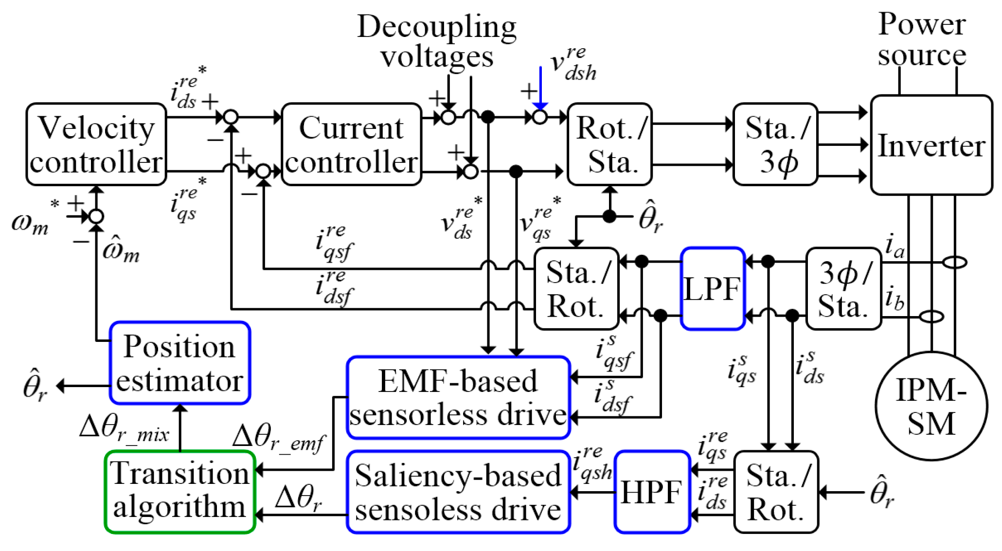
Figure 1 displays the block diagram of the control system. The saliency-based sensorless algorithm estimates the rotor position at zero speed and low speeds through high-frequency (HF) square-wave voltage injection, whereas the back-EMF-based sensorless algorithm estimates the rotor position at intermediate and high speeds. A transition procedure merges the results to estimate the rotor position when the motor is operating in the transition speed region. These aforementioned algorithms are briefly explained in this section.
The stator voltage for the PMSM in the rotor reference frame can be expressed as follows:
[ v q s r v d s r ] = [ r s + s L q s ω r L d s ω r L q s r s + s L d s ] [ i q s r i d s r ] + [ ω r λ m 0 ]
where v q s r , v d s r , i q s r , and i d s r are the q- and d-axis voltages and currents, respectively; Lqs and Lds are the q- and d-axis inductance, respectively; rs, ωr, and λm are the phase resistance, rotor speed, and magnet flux, respectively; and s is the differential operator.

2.1. Saliency-Based Sensorless Control

As displayed in Figure 1, a square-wave voltage ( v d s h r e ) is injected in the estimated d-axis and the saliency spatial signal is extracted from the induced q-axis current. The superscript re indicates that the quantity is in the estimated rotor reference frame, and vinj denotes the magnitude of the injection voltage. The induced difference currents are given as follows:
[ Δ i q s h r e Δ i d s h r e ] = s i g n ( ± v i n j ) ± v i n j Δ T ( L Σ 2 L Δ 2 ) [ L Δ s i n ( 2 Δ θ r ) L Σ + L Δ c o s ( 2 Δ θ r ) ]
and
L Σ = ( L q s + L d s ) / 2 , L Δ = ( L q s L d s ) / 2
Δ θ r = θ r θ ^ r
where the subscript h denotes the HF quantities, θr is the rotor position, ΔT is the inverse of injection frequency, and θ ^ r denotes the estimated rotor position. As indicated in (2), when the estimated rotor frame is not aligned with the actual one, a 2Δθr position-dependent current signal is generated in both the d- and q-axis currents. The ± sign compensation is necessary due to the square-wave voltage injection. Moreover, a high-pass filter is implemented to remove the fundamental component for calculating the difference current. When the position error is sufficiently small, the current signal in the q-axis can be rewritten as
Δ i q s h r e v i n j Δ T L Δ ( L Σ 2 L Δ 2 ) 2 Δ θ r = k e r r Δ θ r
Thus,
Δ θ r Δ i q s h r e / k e r r
The rotor position can be estimated from the measured q-axis difference current by using a closed-loop estimator. Note that the injection voltage and frequency is 60 V and 9 kHz, respectively.

2.2. Back-EMF-Based Sensorless Control

The rotor position can be estimated by tracking the extended back-EMF voltage [6]. Equation (1) can be rewritten as:
[ v q s s v d s s ] = [ r s + L d s s P ω   m L Δ P ω   m L Δ r s + L d s s ] [ i q s s i d s s ] + [ e q s e d s ]
where eqs = Eb·cos(θr) and eds = −Eb·sin(θr) represent the extended back-EMF along the q- and d-axes, respectively; E b = L Δ ( p i q s r ω r i d s r ) + ω r λ m ; and 
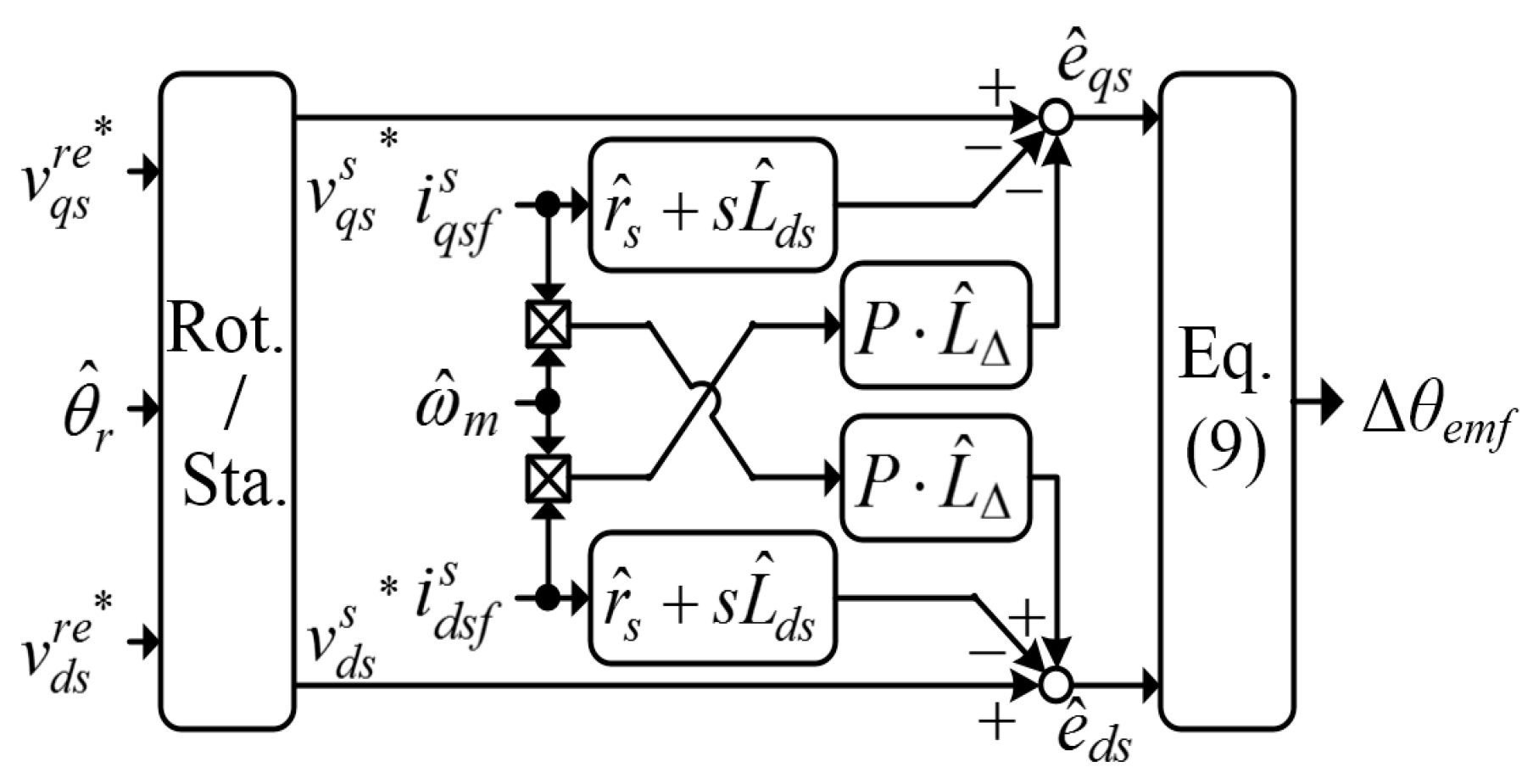
P represents the pole pairs of rotor poles. When the motor parameters are known, the extended back-EMF is calculated as follows:
[ e ^ q s e ^ d s ] = E ^ b [ c o s ( θ r _ e m f ) s i n ( θ r _ e m f ) ] = [ v q s s v d s s ] [ r ^ s + L ^ d s s P ω ^ m L ^ Δ P ω ^ m L ^ Δ r ^ s + L ^ d s s ] [ i q s f s i d s f s ]
where the subscript f is the fundamental frequency components, “*” denotes the command value, “^” denotes the estimated value, ωm is the mechanical speed., and θr_emf is the rotor position estimated from the extended back-EMF. A low-pass filter with cutoff frequency of 3 kHz is used to remove the HF current components to avoid HF noise. A position error dependent signal (Δθemf) is then extracted from the following vector product:
Δ θ e m f = ( e ^ q s s i n θ ^ r e ^ d s c o s θ ^ r ) s i g n ( ω ^ m ) | E ^ b | = s i g n ( ω ^ m ) E b | E ^ b | s i n ( θ r _ e m f θ ^ r )
The estimated back-EMF voltage is normalized with its magnitude. Figure 2 presents the formulas for calculating e ^ q s , e ^ d s , and Δθemf. When the position error is sufficiently small, Δθemf can be approximated as follows:
Δ θ e m f s i g n ( ω ^ m ) ( θ r _ e m f θ ^ r )
Thus, the rotor position can be estimated by controlling Δθemf to zero with a closed-loop estimator.

2.3. Transition Period Control

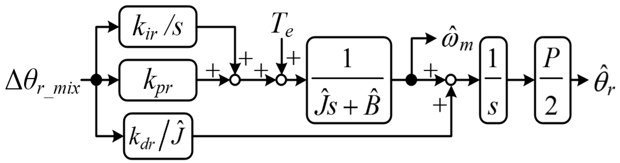
In the transition speed region, a speed-dependent weighting function combines the position errors generated in (6) and (10) as follows:
Δ θ r _ m i x ( 1 G ω ) Δ θ r + G ω Δ θ r _ e m f
where Gω is a linear weighting function with a maximum value of 1 and minimum value of 0. The position estimator illustrated in Figure 3 is used to estimate the rotor position and speed by converging Δθr_mix to zero. J denotes the combined rotor and load inertia, B denotes the frictional torque coefficient, and Te is the motor torque command. The estimator gains kir, kpr, and kdr are tuned using the pole-placement method to track the actual rotor position and speed with the desired dynamic response.

3. Restarting A Spinning PMSM without Position and Speed Feedback

As displayed in 
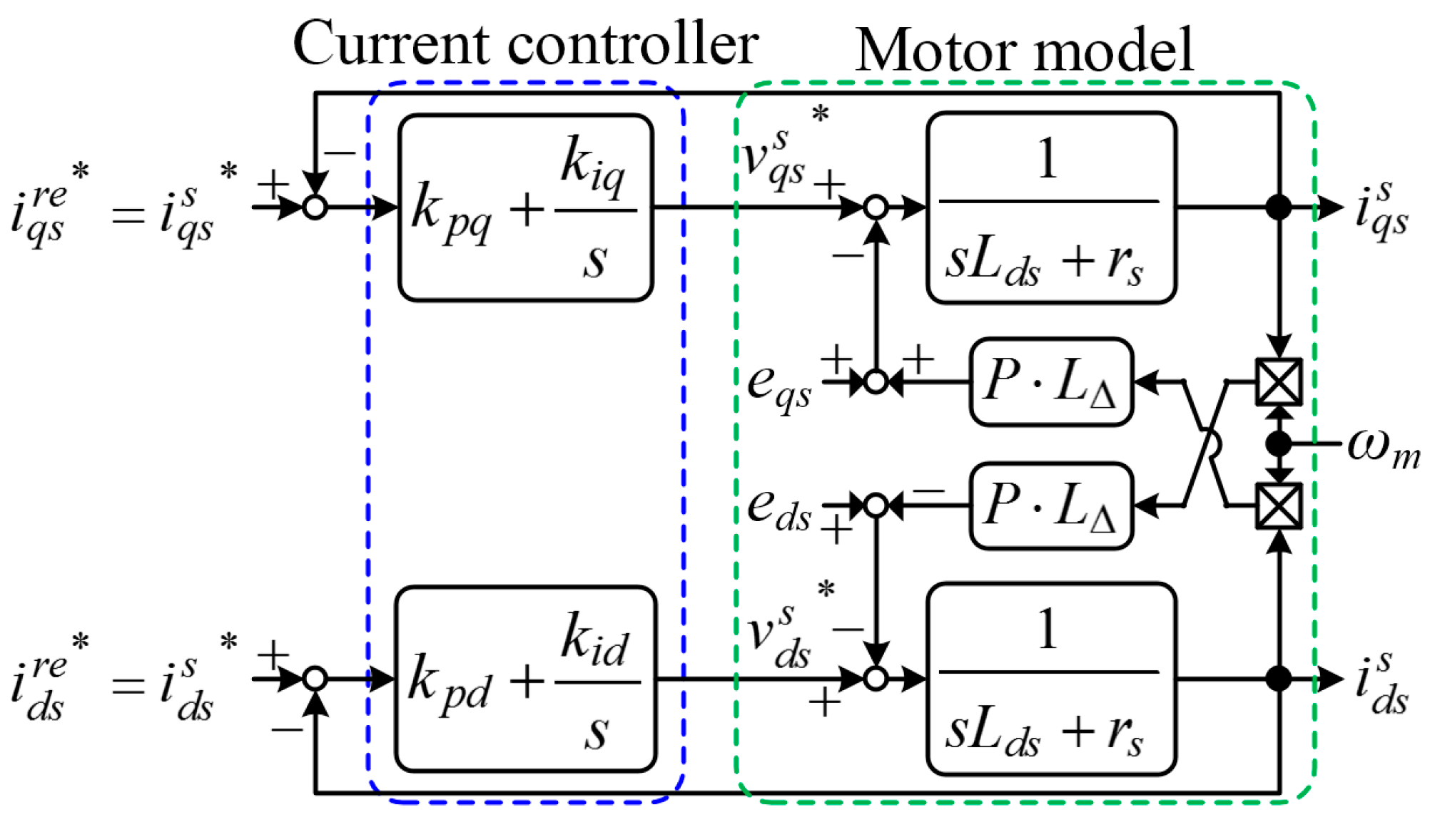
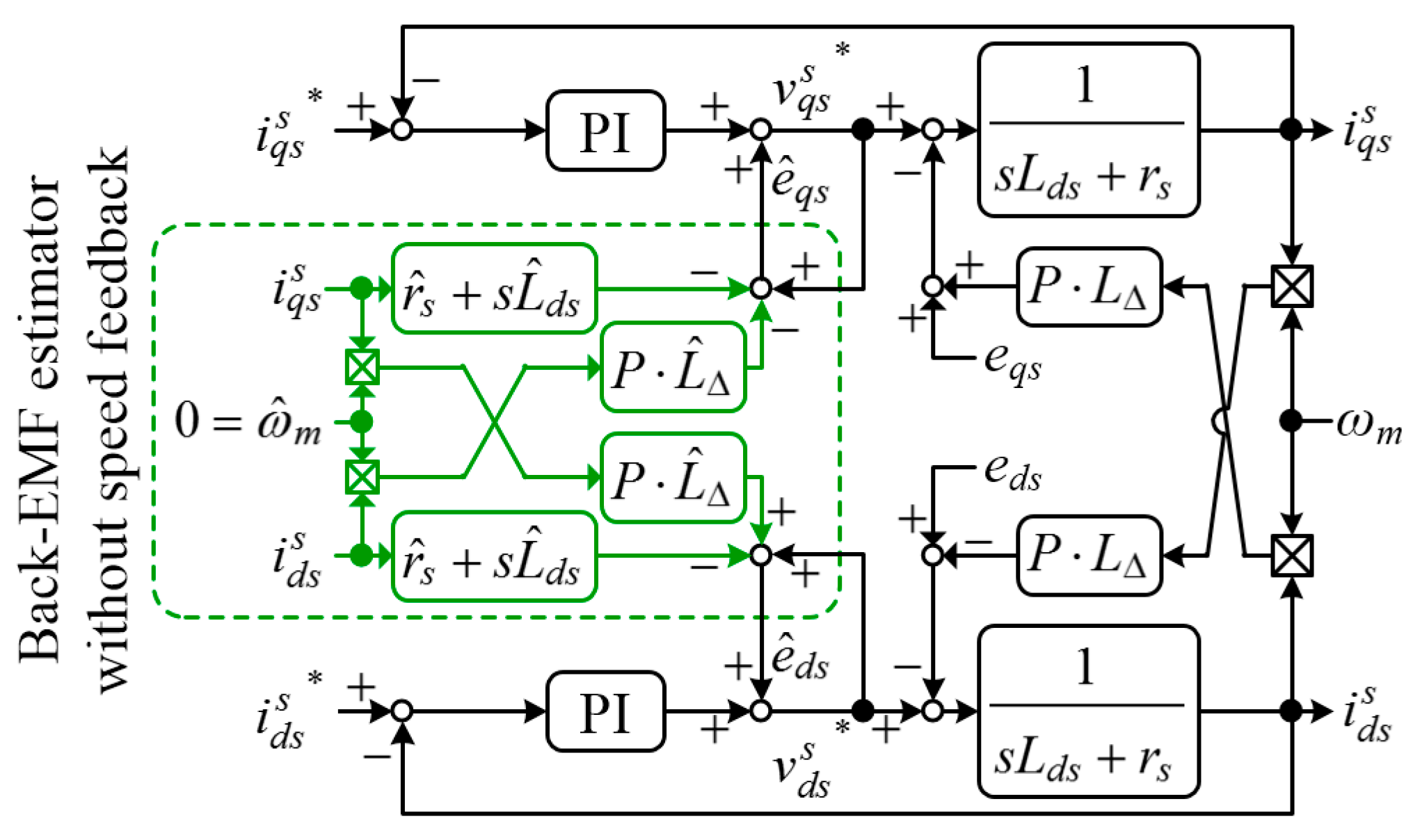
Figure 1, the current controllers require the motor position and speed feedback for vector control and calculating the decoupling voltages. However, when starting a spinning PMSM without position or speed feedback, the current controllers become a stationary frame controller accordingly. Therefore, the current controllers are regulating the AC quantities and their performance is degraded due to the absence of the decoupling voltages and position feedback, as displayed in Figure 4. The voltage commands become stationary frame quantities, and the back-EMF becomes a disturbance to the current controllers. Because the cross-coupling voltages (i.e., P ω m L Δ i q s s and P ω m L Δ i d s s 
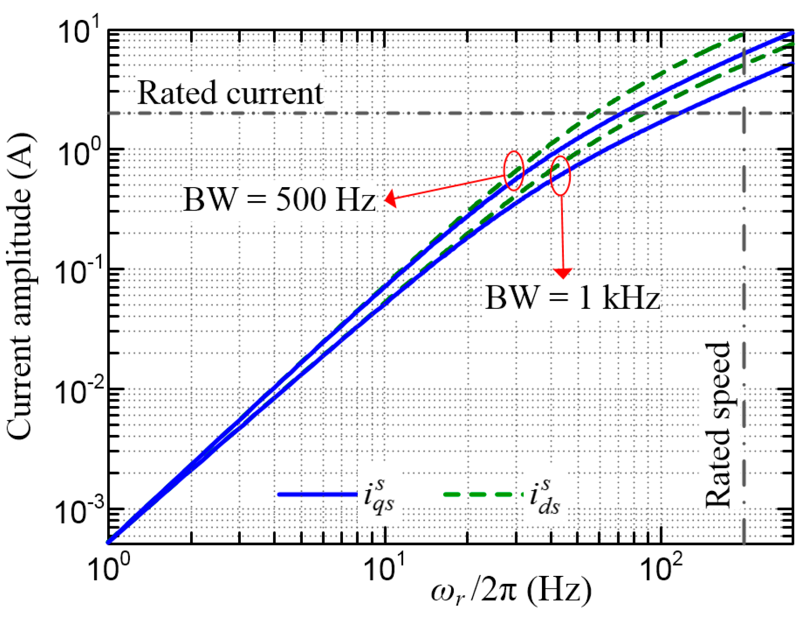
) are generally much smaller than the back-EMF, these voltages are neglected in the following analysis. The current commands are set to zero to obtain zero torque expectantly during restarting period. From Figure 4, the transfer functions between the current and back-EMF can be approximated as
i q s s e q s s L d s s 2 + ( r s + k p q )   s + k i q
i d s s e d s s L d s s 2 + ( r s + k p d )   s + k i d
where kpq, kiq and kpd, kid are the proportional and integral gain for the q- and d-axis current controller, respectively.
Figure 5 shows the stator current responses at a set current controller bandwidth (BW) of 500 Hz and 1 kHz. The PMSM parameters used for the calculations are presented in Appendix A. The amplitude of the induced current is highly dependent on the rotor speed and current controller BW. A higher rotor speed and lower controller BW yield a larger current. Moreover, the amplitude of the induced current at the rated speed is approximately 2.5 times the rated current at the current controller BW of 1 kHz. Consequently, the induced current may cause overcurrent fault and bring the motor back to the coasting state.
Solving (12) and (13) through the inverse Laplace transform can yield the steady-state induced currents as follows:
i q s s ( t ) = 2 ( E b / Z e q ) c o s ( ω   r t + φ q )
i d s s ( t ) = 2 ( E b / Z e d ) s i n ( ω   r t + φ d )
where Zeq and Zed are the equivalent impedances and φq and φd are the equivalent phases. The equivalent impedances and phases are given as follows:
[ Z e q Z e d ] = [ 4 ω   r 2 ( r s + k p q )   2 + 4 ( k i q L d s ω   r 2 )   2 / ω r 4 ( L d s ω   r 2 k i d )   2 + 4 ω r 2 ( r s + k p d )   2 / ω r ]
[ φ q φ d ] = [ s i n 1 ( 2 ( k i q L d s ω r ) Z e q ) 90 ° s i n 1 ( 2 ω   r ( r s + k p d ) Z e d ) ]
The braking torque (
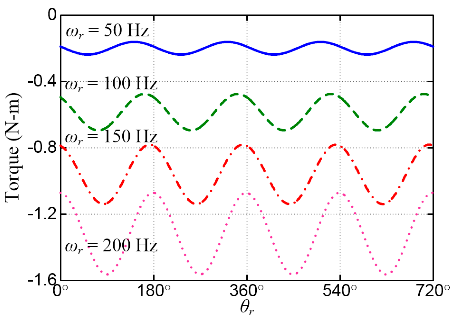
Teb) produced by the induced current can be calculated by substituting (14) and (15) into the following expression:
T e b = 3 4 P λ m ( c o s θ r i q s s s i n θ r i d s s ) 3 2 P L Δ ( s i n θ r i q s s + c o s θ r i d s s ) ( c o s θ r i q s s s i n θ r i d s s )
Figure 6 illustrates the values of Teb for various speeds. Both average and pulsating braking torques exist when the motor is restarted at high speeds. A large average braking torque can cause the motor to brake unexpectedly. This torque also represents the regenerative power generated by the motor. A large regenerative power may cause a rapid rise in the DC-link voltage and potential damage to the front-end power supply.

4. Proposed Restarting Strategy

As the potential danger mentioned in previous section, the back-EMF-induced current must be suppressed to safely start a spinning PMSM. This can be achieved through the accurate and prompt decoupling of the back EMF as soon as the current controller is activated. The strategy presented in the following text uses the estimators displayed in Figure 2 and Figure 3 extensively.

4.1. Back-EMF Estimation without Speed Feedback

The relationship between the estimated and actual back EMF can be derived by substituting (7) into (8), which yields the following equations:
e ^ q s = G 1 e q s + v q s s G 1 v q s s + P ( G 1 ω m L Δ ω ^ m L ^ Δ )   i d s s
e ^ d s = G 1 e d s + v d s s G 1 v d s s + P ( ω ^ m L ^ Δ G 1 ω m L Δ )   i q s s
where G 1 = ( s L ^ d s + r ^ s ) / ( s L d s + r s ) . All the currents are fundamental components, and the subscript f is neglected for convenience. The mismatch in parameters such as Lds and rs causes amplitude and phase errors between the estimated and actual back-EMF. Moreover, inverter nonlinearity, such as the dead-time effect, also results in errors in the estimated back-EMF. To mitigate these errors, these motor parameters are measured with reasonable accuracy and the dead-time effect is compensated [20,21,22]. Consequently, G1 ≈ 1, v q s s G 1 v q s s ≈ 0, and v d s s G 1 v d s s ≈ 0. Thus, (19) and (20) are simplified to the following equations:
e ^ q s e q s + P ( ω m L Δ ω ^ m L ^ Δ )   i d s s
e ^ d s e d s + P ( ω ^ m L ^ Δ ω m L Δ )   i q s s
Because the rotor speed is not yet identified, the estimated speed is set to zero. Therefore, (21) and (22) are transformed into the following equations:
e ^ q s e q s + P ω m L Δ i d s s
e ^ d s e d s + P ω m L Δ i q s s
The stator currents in the aforementioned equations can be eliminated by combining (12) and (13) and (23) and (24). Moreover, note that e q s = s e d s / ω r and e d s = s e q s / ω r . Then, the estimated back EMF can be expressed as
e ^ q s e q s = ( 2 L q s / L d s )   s 2 + ( r s + k p q )   s / L d s + k i q / L d s s 2 + ( r s + k p q )   s / L d s + k i q / L d s
e ^ d s e d s = ( 2 L q s / L d s )   s 2 + ( r s + k p d )   s / L d s + k i d / L d s s 2 + ( r s + k p d )   s / L d s + k i d / L d s
Figure 7 depicts the frequency responses of the aforementioned functions at various saliency ratios. The current controller BW is set to 1 kHz. The estimated back-EMF approaches the actual back EMF at low speeds. However, significant errors exist at high speeds for machines with a high saliency ratio. The saliency ratio of most of the PMSMs available on the market is less than 2. In addition, the BW of the current controller usually is set as high as possible. Therefore, the amplitude and phase errors for PMSMs are acceptable at speeds lower than the BW of the current controller.
Most importantly, the above analysis indicates that the back EMF at the restarting period can be estimated with reasonable accuracy without position or speed feedback by using the estimator presented in Figure 2.

4.2. Back-EMF Decoupling

Figure 8 illustrates the current controller and back-EMF estimator when the restarting procedure is implemented. Note that the estimated speed is set to zero because it is not identified yet. The back EMF of the motor is estimated as soon as the inverter and current controller are activated, and the estimated back-EMF is applied to decouple the actual back-EMF. Because the back-EMF estimator is effectively in the stationary frame during the restarting period, and most importantly, contains no integrator, the settling time of the back-EMF estimator is inherently zero. Therefore, the back-EMF can be estimated within one sampling period. Then, the inverter outputs the estimated back-EMF to the motor within two sampling periods after the drive is activated. Because the back- EMF can be decoupled within a very short time, the induced current can be suppressed promptly.

4.3. Transient Current Suppression

Because the current controller initiates closed-loop control as soon as the restarting procedure begins, the initial values in the integrators should be set accordingly. Otherwise, the stator current may require a relatively long time to reach the steady state even if the back-EMF is decoupled. From Equation (7), both the resistive voltage drop and cross-coupling voltage are neglected because they have minor contributions to the current response. The initial motor current can be approximated as follows:
L d s s [ i q s s i d s s ] [ e q s e d s ]
Because the back-EMF varies slower than the sampling period, the currents can be reasonably assumed to increase linearly during the restarting period. Moreover, because transient current suppression occurs in a very short time, the initial controller voltage is analyzed in the discrete domain.
The sampling period is Ts, and the drive activates at t1. The controller voltages are calculated at t1 + Ts, and output to the motor at t1 + 2Ts due to the pulse width modulation delay. The subsequent motor currents are sampled at t1 + 3Ts. To force the motor current sampled at t1 + 3Ts to be zero, the initial controller voltages (i.e., vqsc and vdsc) should be set as follows:
v q s c ( t 1 + 3 T s ) = L d s i q s s ( t 1 + 3 T s ) i q s s ( t 1 ) ( t 1 + 3 T s ) ( t 1 + 2 T s )
v d s c ( t 1 + 3 T s ) = L d s i d s s ( t 1 + 3 T s ) i d s s ( t 1 ) ( t 1 + 3 T s ) ( t 1 + 2 T s )
Equations (28) and (29) cannot be evaluated because future currents are used. However, the currents sampled at t1 + 3Ts can be predicted according to the constant back-EMF assumption as
i q s s ( t 1 + 3 T s ) = 3 i q s s ( t 1 + T s ) 2 i q s s ( t 1 )
i d s s ( t 1 + 3 T s ) = 3 i d s s ( t 1 + T s ) 2 i d s s ( t 1 )
When (30) and (31) are substituted into (28) and (29), the initial controller voltages can be calculated as
v q s c s ( t 1 + T s ) = 3 L d s i q s s ( t 1 + T s ) i q s s ( t 1 ) T s
v d s c s ( t 1 + T s ) = 3 L d s i d s s ( t 1 + T s ) i d s s ( t 1 ) T s
Figure 9 illustrates the activation procedure of the restarting strategy. The predicted initial controller voltages are applied as soon as the drive is activated. These voltages force the currents to decrease to zero within three sampling periods.

5. Experimental Results

A 400 W, a four-pole PMSM was used for experimental verifications. The parameters of the PMSM are provided in Appendix A. 
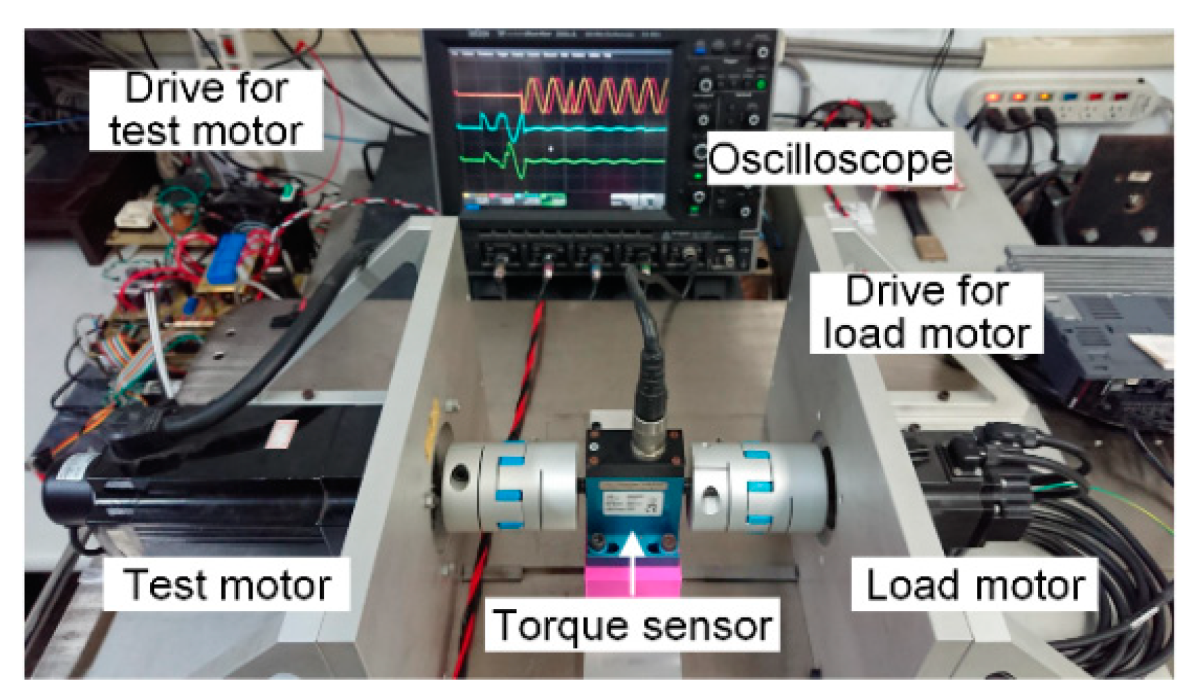
Figure 10 shows the experimental system. The sensorless control and restarting control algorithms were implemented using a Texas Instruments TMS320F28335 digital signal processor. The sampling frequencies for current and velocity control were 18 kHz (Ts = 56 µs) and 2.2 kHz, respectively. The bandwidths of the current and velocity controller were tuned to 1000 and 25 Hz, respectively. The DC-link voltage was 300 V. The transition speed for the saliency-based and back-EMF-based sensorless control algorithm was 600–900 rpm. A load motor provided external load to the test motor. The actual rotor position and speed were monitored by an encoder with a resolution of 2500 pulse/rev.
Figure 11 depicts the measured steady-state currents and estimated back-EMF when the current controllers were activated without speed or position feedback. No decoupling voltage was applied. Both the current commands were set to zero, and the motor speed was regulated at 3000 rpm by the load motor. Significant induced currents existed due to the undecoupled back-EMF. The motor currents at various speeds were measured and compared with the calculated values obtained using (14) and (15). The calculated and measured results are summarized in Table 1. As indicated in Table 1, the measurements highly agreed with the calculated values. The results list in Table 1 also demonstrate the validity of the assumption in (12)–(13) that the cross-coupling voltages are small enough to be ignored. 
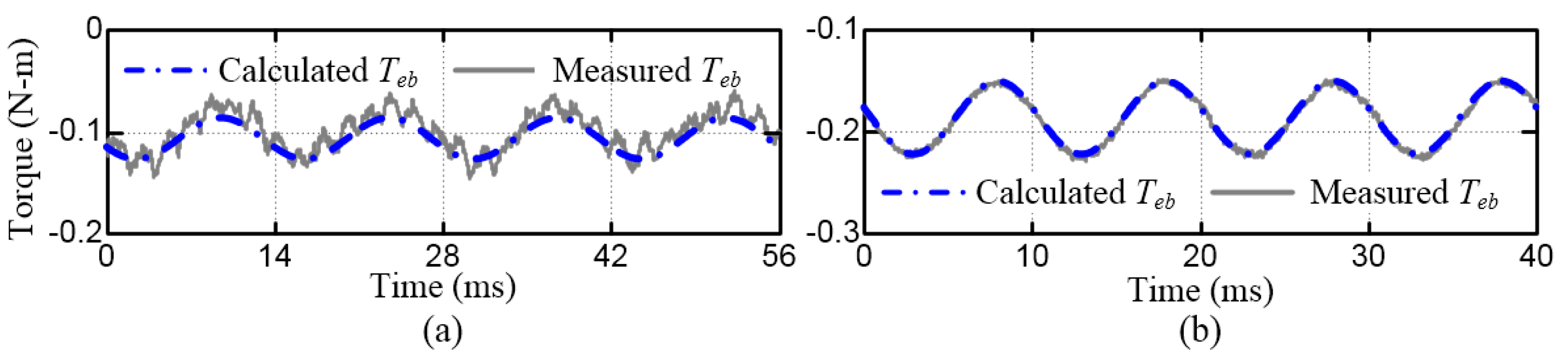
Figure 12a,b illustrates a comparison of the measured and calculated braking torques at 1080 and 1500 rpm, respectively. The braking torque was measured using a torque sensor. The frequency of the torque ripple was twice the rotor speed. Moreover, when HF components were ignored, the measured torque was highly consistent with the values calculated using (18).
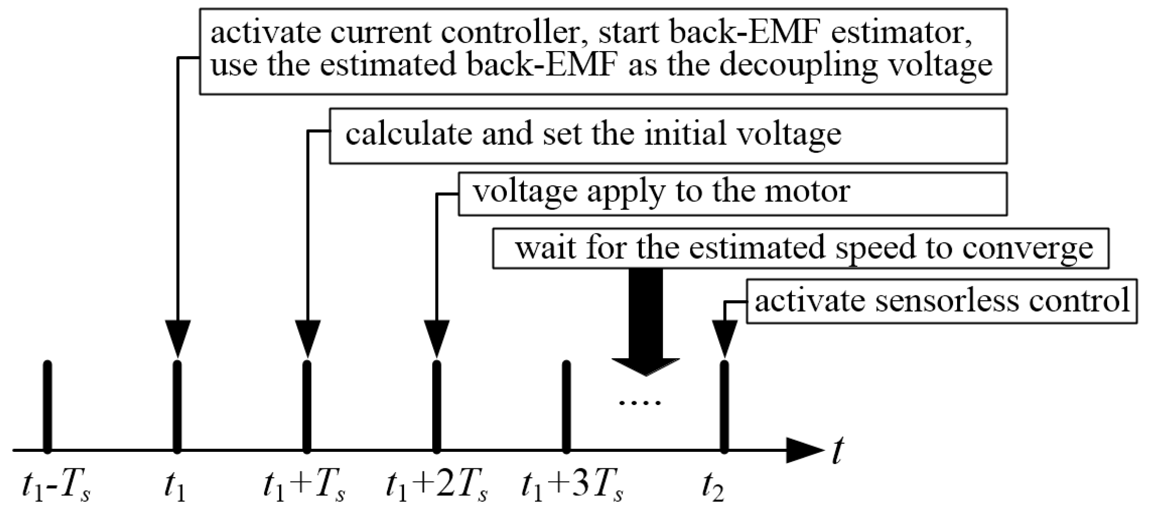
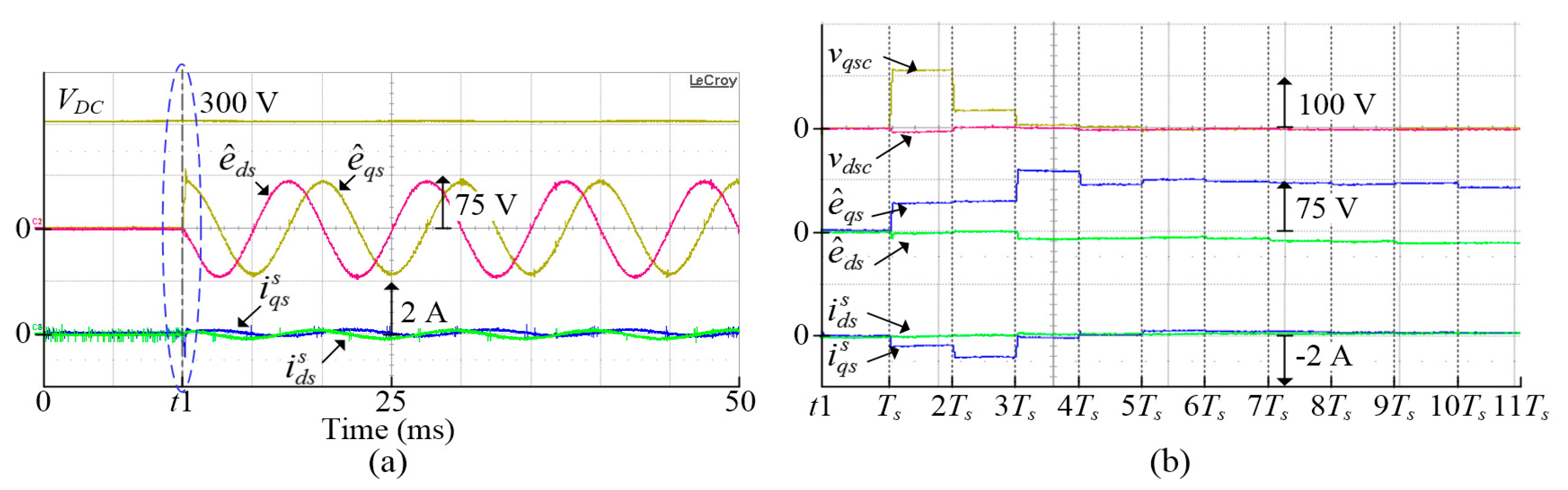
Figure 13 presents the current responses when the back-EMF was decoupled and the initial controller voltage was set to zero. The motor speed was regulated at 3000 rpm by the load motor, and the current commands were set to zero. The drive was activated with the proposed restarting strategy at t1. The back EMF was estimated at t1 + Ts and applied to the motor at t1 + 2Ts. However, motor currents require approximately eight sampling periods to settle down after the drive is activated. 
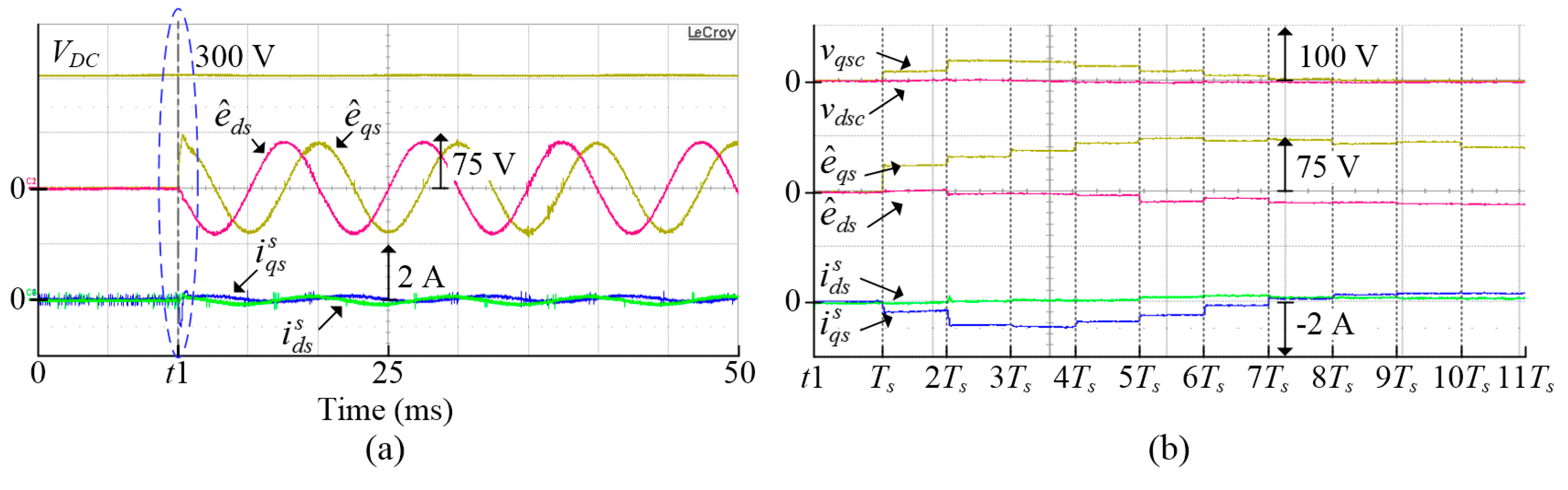
Figure 14 displays the results when the initial controller voltages were calculated using (32) and (33) under experimental conditions similar to those in Figure 13. The motor currents settled down within only four sampling periods. This indicates that the motor currents increase linearly in such short time, and the assumption used for the initial controller voltages calculation in Section 4.3 is reasonable. Table 2 provides a summary of the maximum amplitude and settling time of the measured currents when the motor started from various rotor positions at 3000 rpm. All the maximum currents were less than half the rated current, and the settling times were 4–5 times Ts. These results indicate that the back-EMF-induced current can be effectively suppressed with the proposed restarting strategy.
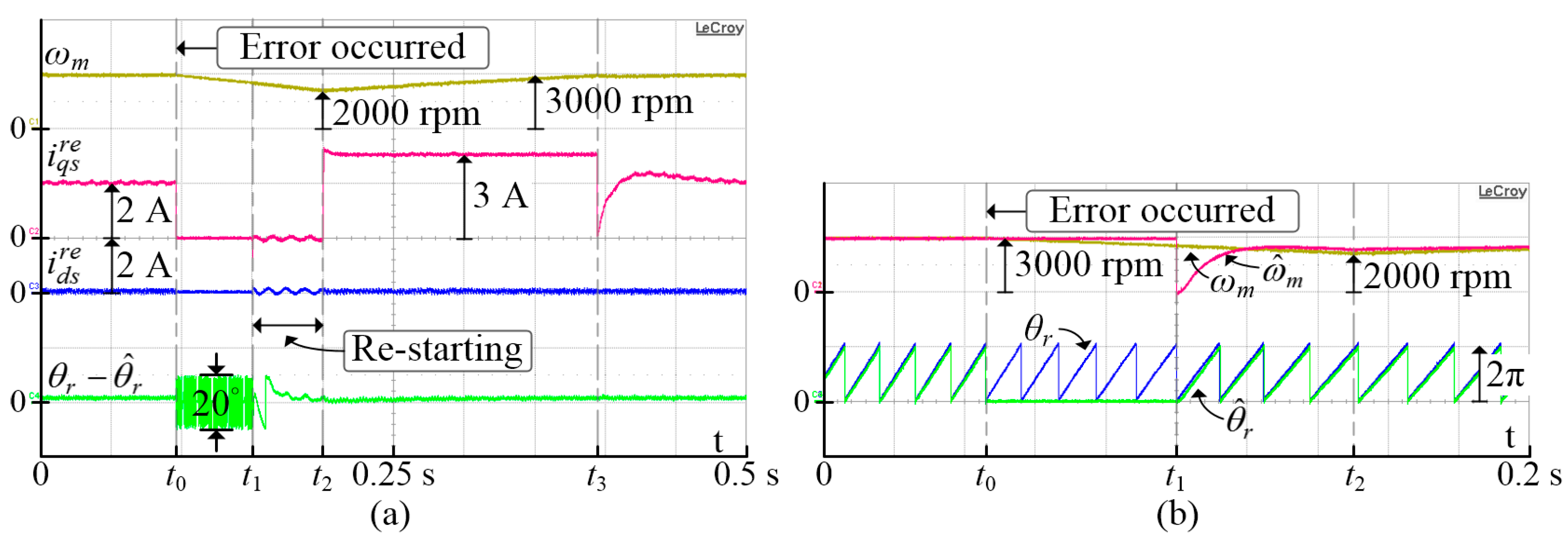
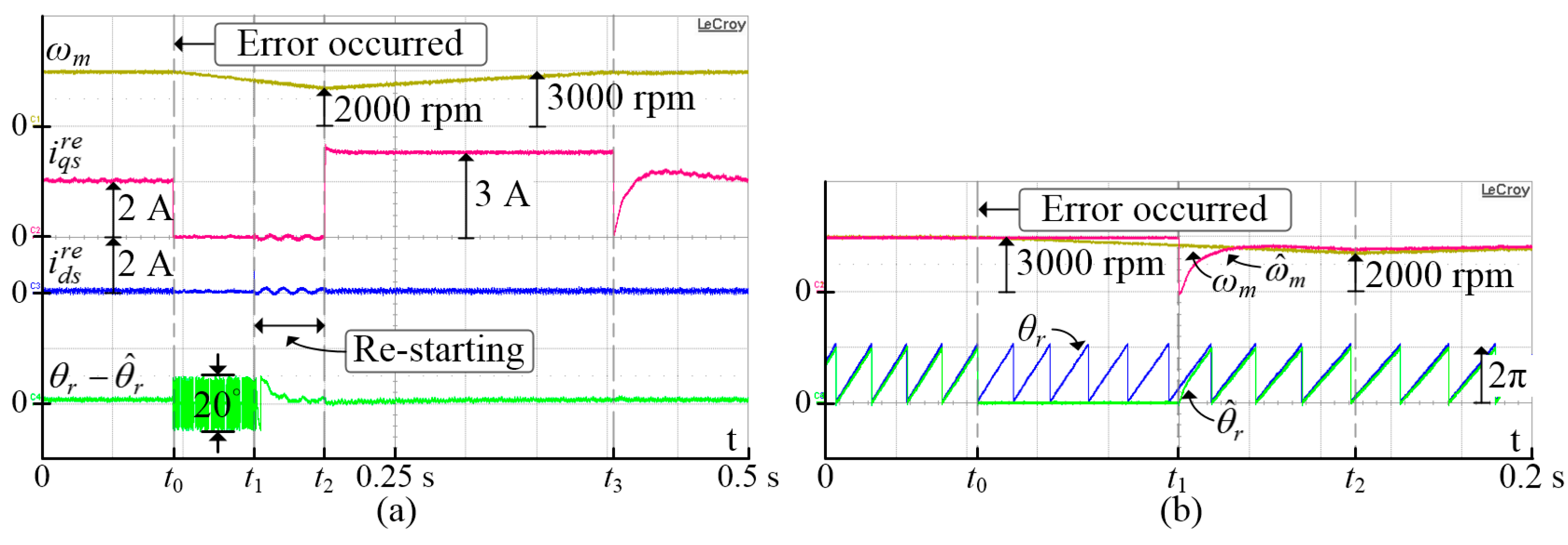
Figure 15 and Figure 16 show the results obtained when the motor was running at 3000 rpm with the rated load and then restarted from an unexpected error occurrence at θr = 0° and 90°, respectively.
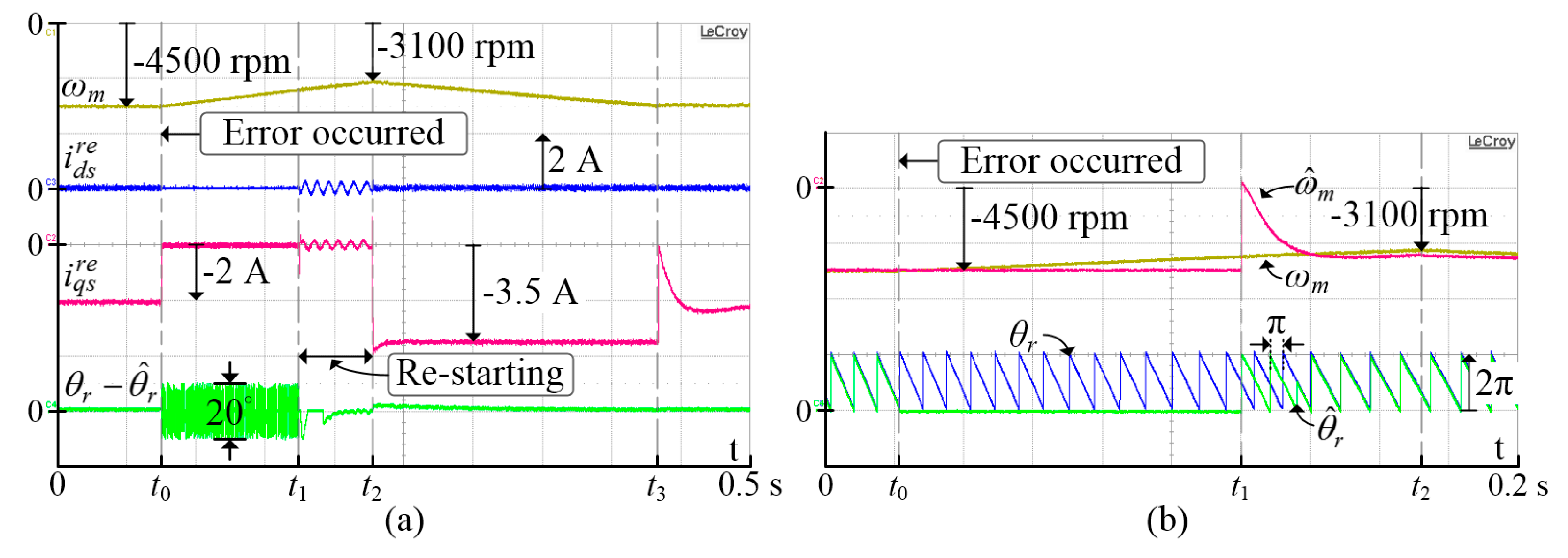
 Figure 17 and 
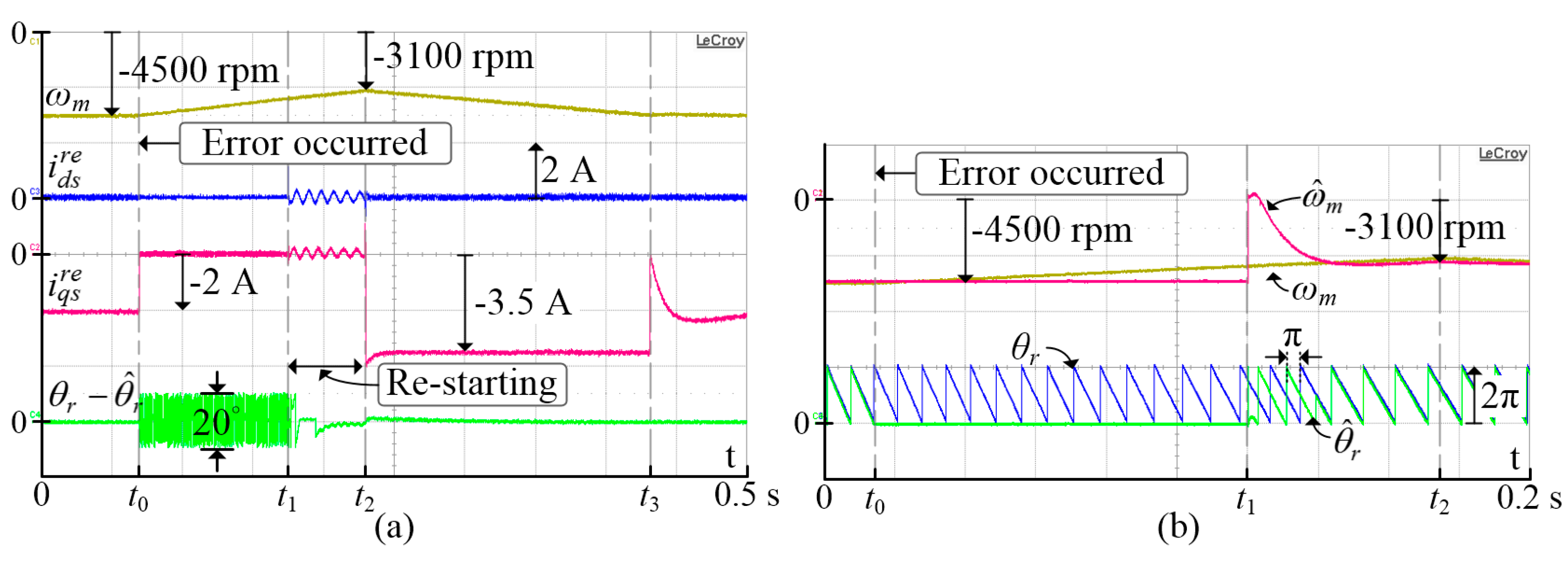
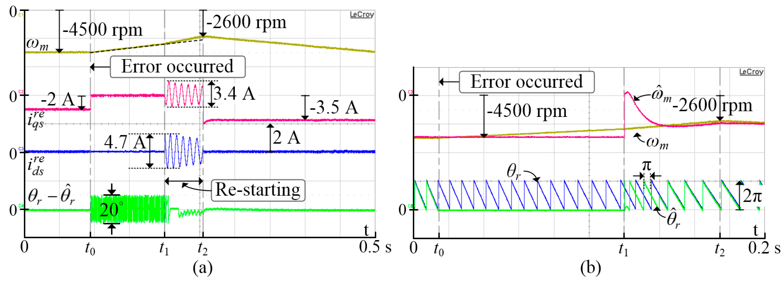
Figure 18 illustrate the results obtained when the motor was running at −4500 rpm with the rated load and then restarted from an unexpected error at θr = 180° and 270°, respectively. The motor was initially controlled through sensorless control and subjected to the rated load. The motor drive was turned off at t0 to emulate the occurrence of an error, such as sensor failure or temporary power disruption. Subsequently, the motor coasted down rapidly between t0 and t1 due to the large external load torque. The drive was then activated using the proposed restarting strategy at t1. After the estimated speed and position reached the steady state at t2, sensorless control was performed again with constant current commands to increase the motor speed. Finally, the system switched back to the regular sensorless speed control after the motor speed reached the preset command (3000 and −4500 rpm).
According to the above results, all the transient currents at t1 were very small, which indicates that the back-EMF-induced currents had been effectively suppressed irrespective of the starting speed or position. The amplified waveforms also indicate that the rotor position and speed could be estimated correctly irrespective of the rotation direction. Although the estimated position reached the actual position rapidly, the estimated speed required approximately 0.02 s to reach the actual speed. Therefore, the duration between t1 and t2 should be higher than 0.02 s for a smooth restart of the sensorless control. Most importantly, although the position estimator takes longer time to estimate the actual speed correctly, the induced current is still suppressed effectively because the back-EMF can be estimated accurately without the speed feedback. Actually, this is one of the key features of the proposed restarting strategy. Note also that for a negative speed, a 180° phase error appeared in the estimated position due to the normalization of Δθemf. The correct rotor position was obtained after the rotation direction was identified and the phase error was compensated. Additionally, as shown in Figure 15, Figure 16, Figure 17 and Figure 18, the position error ( θ r θ ^ r ) after t2 approximates to 0° because the motor parameters are measured with reasonable accuracy and the nonlinearity of the inverter is well compensated.
Figure 19 displays the results of an experiment conducted under similar conditions to those for the experiment displayed in Figure 18 but with direct restarting of the motor. The back-EMF is not decoupled and the initial voltage is not applied when the motor is directly restarted. Although the motor speed and position could be still estimated with high accuracy, significant back-EMF-induced currents appeared between t1 and t2 because the back-EMF was not decoupled. Moreover, the motor coasted down faster in the experiment displayed in Figure 19 than in the experiment displayed in Figure 18 due to the large braking torque.
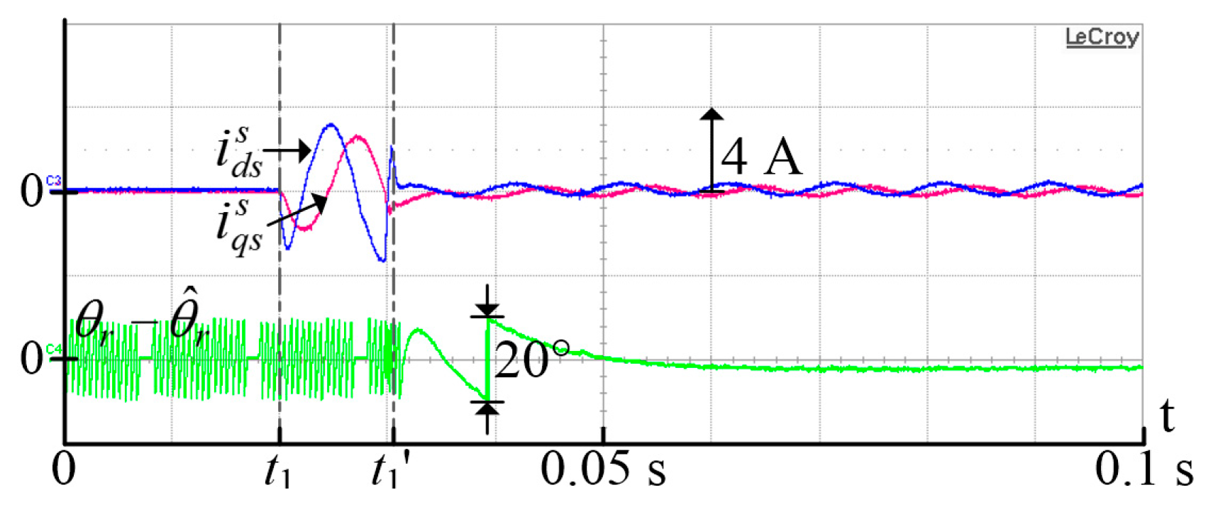
Figure 20 presents the currents and position errors when the motor speed was regulated by the load motor at 3000 rpm, current commands were set to zero, and BW of the current controller was set to 500 Hz. The current controller was activated at t1, and the restarting strategy was implemented at t1’ to examine its effectiveness. It can be seen that the position error is obviously larger than that in Figure 15, Figure 16, Figure 17 and Figure 18 because low BW of the current controllers causes significant phase delay on the estimated back-EMF, as mentioned in Section 4.1. In addition, a large transient current was induced between t1 and t1’. However, the induced current was suppressed as soon as the restarting procedure was implemented. This result also confirms that the proposed restarting strategy is effective even with a considerably low current controller bandwidth.

6. Conclusions

This paper proposes a restarting strategy for back-EMF-based sensorless controlled PMSMs when the rotor is spinning. The proposed restarting strategy presents the following features: (1) the restarting strategy is easy to implement because it is developed based on the existing back-EMF-based sensorless control algorithm; (2) the restarting procedure does not increase the computation burden because no voltage vector injection is required to identify the rotor position and speed; (3) the induced current can be suppressed effectively before the rotor position and speed are identified; (4) the rotor speed and position are still tracked accurately even when the motor is coasting down very quickly.
The analytical results indicate that the back-EMF of the motor can be estimated with good accuracy even without the rotor position or speed feedback provided that the bandwidth of the current controller is much higher than the rotor speed. According to this result, the back-EMF is estimated and used as the decoupling voltage for mitigating the back-EMF-induced currents when activates the current controller. Furthermore, the initial voltages in the integrators of current controllers are calculated properly and applied to greatly reduce the transient current. The experimental results indicate that the induced current can be suppressed within four to five sampling periods for various spinning conditions. Because of the considerably short time delay, the motor drive can restart safely from various speeds and positions without causing overcurrent fault.

Author Contributions

Conceptualization, Z.C.Y. and S.M.Y.; methodology, Z.C.Y.; software, Z.C.Y.; validation, Z.C.Y. and S.M.Y.; formal analysis, Z.C.Y.; investigation, Z.C.Y.; resources, S.M.Y.; data curation, Z.C.Y.; writing—original draft preparation, Z.C.Y.; writing—review and editing, S.M.Y.; visualization, Z.C.Y.; supervision, S.M.Y.; project administration, S.M.Y.; funding acquisition, S.M.Y.

Funding

This research received no external funding.

Conflicts of Interest

The authors declare no conflict of interest.

Appendix A

Table A1. Main motor parameters.
ParameterValueUnit
Rated speed/pole pairs6000/2rpm
Rated current2A
Magnet flux (λm)0.106Wb-turns
Stator resistance1.53Ω
d-axis inductance (Lds)4.8mH
q-axis inductance (Lqs)7.1mH

References

  1. Liu, J.M.; Zhu, Z.Q. Sensorless control strategy by square-waveform high-frequency pulsating signal injection into stationary reference frame. IEEE J. Emerg. Sel. Topics Power Electron. 2014, 2, 171–180. [Google Scholar] [CrossRef]
  2. Yoon, Y.D.; Sul, S.K.; Morimoto, S.; Ide, K. High-Bandwidth sensorless algorithm for AC machines based on square-wave-type voltage injection. IEEE Trans. Ind. Appl. 2011, 47, 1361–1370. [Google Scholar] [CrossRef]
  3. Murakami, S.; Shiota, T.; Ohto, M.; Ide, K.; Hisatsune, M. Encoderless servo drive with adequately designed IPMSM for pulse-voltage-injection-based position detection. IEEE Trans. Ind. Appl. 2012, 48, 1922–1930. [Google Scholar] [CrossRef]
  4. Jung, S.; Ha, J.I. Analog filtering method for sensorless AC machine control with carrier-frequency signal injection. IEEE Trans. Ind. Electron. 2015, 62, 5348–5358. [Google Scholar] [CrossRef]
  5. Yang, S.C.; Yang, S.M.; Hu, J.H. Design consideration on the square-wave voltage injection for sensorless drive of interior permanent-magnet machines. IEEE Trans. Ind. Electron. 2017, 64, 159–168. [Google Scholar] [CrossRef]
  6. Chen, Z.; Tomita, M.; Doki, S.; Okuma, S. An extended electromotive force model for sensorless control of interior permanent-magnet synchronous motors. IEEE Trans. Ind. Electron. 2003, 50, 288–295. [Google Scholar] [CrossRef]
  7. Morimoto, S.; Kawamoto, K.; Sanada, M.; Takeda, Y. Sensorless control strategy for salient-pole pmsm based on extended emf in rotating reference frame. IEEE Trans. Ind. Appl. 2002, 38, 1054–1061. [Google Scholar] [CrossRef]
  8. Kim, H.; Harke, M.C.; Lorenz, R.D. Sensorless control of interior permanent-magnet machine drives with zero-phase lag position estimation. IEEE Trans. Ind. Appl. 2007, 39, 1726–1733. [Google Scholar]
  9. Patel, N.; O’meara, T.; Nagashima, J.; Lorenz, R. Encoderless IPM traction drive for EV/HEV’s. In Proceedings of the Conference Record of the 2001 IEEE Industry Applications Conference. 36th IAS Annual Meeting, Chicago, IL, USA, 30 September–4 October 2001; Volume 3, pp. 1703–1707. [Google Scholar]
  10. Wang, G.; Yang, R.; Xu, D. DSP-Based control of sensorless IPMSM drives for wide-speed-range operation. IEEE Trans. Ind. Electron. 2013, 60, 720–727. [Google Scholar] [CrossRef]
  11. Lara, J.; Chandra, A.; Xu, J. Integration of HFSI and extended-EMF based techniques for PMSM sensorless control in HEV/EV applications. In Proceedings of the IECON 2012—38th Annual Conference on IEEE Industrial Electronics Society, Montreal, QC, Canada, 25–28 October 2012; pp. 3688–3693. [Google Scholar]
  12. Ide, K.; Takaki, M.; Morimoto, S.; Kawazoe, Y.; Maemura, A.; Ohto, M. Saliency-Based sensorless drive of adequate designed IPM motor for robot vehicle application. In Proceedings of the 2007 Power Conversion Conference, Nagoya, Japan, 2–5 April 2007; pp. 1126–1133. [Google Scholar]
  13. Yoo, H.; Kim, J.H.; Sul, S.K. Sensorless operation of a PWM rectifier for a distributed generation. IEEE Trans. Power Electron. 2007, 22, 1014–1018. [Google Scholar] [CrossRef]
  14. Son, Y.C.; Jang, S.J.; Nasrabadi, R.D. Permanent Magnet AC Motor Systems and Control Algorithm Restart Methods. U.S. Patent 8054030B2, 8 November 2011. [Google Scholar]
  15. Son, Y.C.; Jang, J.; Welchko, B.A.; Patel, N.R.; Schulz, S.E. Method and System for Initiating Operation of an Electric Motor. U.S. Patent 8319460B2, 27 November 2012. [Google Scholar]
  16. Taniguchi, S.; Mochiduki, S.; Yamakawa, T.; Wakao, S.; Kondo, K.; Yoneyama, T. Starting procedure of rotational sensorless PMSM in the rotating condition. IEEE Trans. Ind. Appl. 2009, 45, 194–202. [Google Scholar] [CrossRef]
  17. Lee, K.; Ahmed, S.; Lukic, S.M. Universal restart strategy for high-inertia scalar-controlled PMSM drives. IEEE Trans. Ind. Appl. 2016, 52, 4001–4009. [Google Scholar] [CrossRef]
  18. Iura, H.; Ide, K.; Hanamoto, T.; Chen, Z. An estimation method of rotational direction and speed for free-running AC machines without speed and voltage sensor. IEEE Trans. Ind. Appl. 2016, 47, 153–160. [Google Scholar] [CrossRef]
  19. You, Z.C.; Yang, S.M. A Control strategy for flying-start of shaft sensorless permanent magnet synchronous machine drive. In Proceedings of the 2018 International Power Electronics Conference (IPEC-Niigata 2018-ECCE Asia), Niigata, Japan, 20–24 May 2018; pp. 651–656. [Google Scholar]
  20. Yang, S.M.; Lin, K.W. Automatic control loop tuning for permanent-magnet AC serve motor drives. IEEE Trans. Ind. Electron. 2016, 63, 1499–1506. [Google Scholar] [CrossRef]
  21. Inoue, Y.; Yamada, K.; Morimoto, S.; Sanada, M. Effectiveness of voltage error compensation and parameter identification for model-based sensorless control of IPMSM. IEEE Trans. Ind. Appl. 2009, 45, 213–221. [Google Scholar] [CrossRef]
  22. Hejny, R.W.; Lorenz, R.D. Evaluating the practical low-speed limits for back-EMF tracking-based sensorless speed control using drive stiffness as a key metric. IEEE Trans. Ind. Appl. 2011, 47, 1337–1343. [Google Scholar] [CrossRef]
Figure 1. Overall control system for the full-speed region sensorless speed drive.
Energies 12 01818 g001
Figure 2. Extended back-EMF estimator.
Energies 12 01818 g002
Figure 3. Rotor position and speed estimator.
Energies 12 01818 g003
Figure 4. Equivalent stationary frame current control loop.
Energies 12 01818 g004
Figure 5. Frequency response of the induced current.
Energies 12 01818 g005
Figure 6. Braking torque produced by the induced current at different rotor speed.
Energies 12 01818 g006
Figure 7. Frequency response of (a) e ^ q s / e q s ; (b) e ^ d s / e d s .
Energies 12 01818 g007
Figure 8. Current controller with the decoupling voltage from the back-EMF estimator during restarting period.
Energies 12 01818 g008
Figure 9. Activation of the restarting strategy.
Energies 12 01818 g009
Figure 10. Experimental system.
Energies 12 01818 g010
Figure 11. Measured steady-state currents and estimated back-EMF when the current controllers were activated without speed and position feedback and with no decoupling voltage.
Energies 12 01818 g011
Figure 12. Comparison of the measured and calculated braking torque at (a) 1800 rpm and (b) 1500 rpm.
Energies 12 01818 g012
Figure 13. (a) Current responses when the back-EMF was decoupled but the initial controller voltage was set to zero (the motor speed was regulated at 3000 rpm by the load motor); (b) Amplified waveforms around t1.
Energies 12 01818 g013
Figure 14. (a) Current responses when the back-EMF was decoupled and the initial controller voltage was set to the value calculated by (32) and (33) (the motor speed was regulated at 3000 rpm by the load motor); (b) Amplified waveforms around t1.
Energies 12 01818 g014
Figure 15. (a) Restarting of the motor from θr = 0° with a positive speed under the rated load; (b) Amplified waveforms.
Energies 12 01818 g015
Figure 16. (a) Restarting of the motor from θr = 90° with a positive speed under the rated load; (b) Amplified waveforms.
Energies 12 01818 g016
Figure 17. (a) Restarting of the motor from θr = 180° with a negative speed under the rated load; (b) Amplified waveforms.
Energies 12 01818 g017
Figure 18. (a) Restarting of the motor from θr = 270° with a negative speed under the rated load; (b) Amplified waveforms.
Energies 12 01818 g018
Figure 19. (a) Restarting the motor directly from θr = 270° with a negative speed under the rated load; (b) Amplified waveforms.
Energies 12 01818 g019
Figure 20. Currents and position errors during restarting period when the current controller BW was set to 500 Hz.
Energies 12 01818 g020
Table 1. Comparison of the measured and calculated currents at various speeds.
ωm
(rpm)
CurrentMeas.Calc.Meas.Calc.
Amplitude (A)Phase (°)
1500 i q s s 0.670.61–149.7–147.8
i d s s 0.840.78–133.7–137.4
3000 i q s s 1.481.4–164.9–165.1
i d s s 2.071.96–153.2–158.8
4500 i q s s 2.432.15–170.3–173
i d s s 3.363.1–162.2–169.9
Table 2. Measured currents at various positions when the restarting strategy is implemented.
θr (°)Maximum Amplitude (A)Settling Time
i q s s i d s s
0–0.860.174Ts
60–0.410.774Ts
900.150.875Ts
1800.91–0.24Ts
2400.48–0.764Ts
2700.23–0.845Ts

