Article

Coordinated Control for Operating Characteristics Improvement of UHVDC Transmission Systems under Hierarchical Connection Scheme with STATCOM

The State Key Laboratory of Alternate Electrical Power System with Renewable Energy Sources, North China Electric Power University, Beijing 102206, China
*
Author to whom correspondence should be addressed.
Energies 2019, 12(5), 945; https://doi.org/10.3390/en12050945
Submission received: 25 January 2019 / Revised: 4 March 2019 / Accepted: 7 March 2019 / Published: 12 March 2019
(This article belongs to the Section F: Electrical Engineering)

Abstract

:
Ultra-high voltage direct current (UHVDC) systems under hierarchical connection schemes (HCSs) linked to AC grids with different voltage levels (500 and 1000 kV) have been a great concern for power utilities to transfer bulk power. They have some operating issues like cascaded commutation failures and longer fault recovery time under certain fault conditions. Since STATCOM has the ability to effectively regulate AC busbar voltages, thus it is considered in this paper to improve the operating characteristics of UHVDC-HCS systems. To further improve the operating characteristics, a coordinated control between an UHVDC-HCS system and STATCOM is presented. To validate the effectiveness of coordinated control, the comparison between different control modes such as reactive power control (Q-control) and voltage control (V-control) in the outer loop control of STATCOM are conducted in detail. Various indices like commutation failure immunity index (CFII) and commutation failure probability index (CFPI) are also comprehensively evaluated in order to investigate robustness of the adopted coordinated control. An UHVDC-HCS system with multiple STATCOMs on the inverter side (500 kV bus) is developed in PSCAD/EMTDC. The impact of coordinated control on commutation failure phenomena and fault recovery time during single and three phase AC faults is analyzed. The analysis shows that coordinated control with V-control mode of STATCOM exhibits better performance in enhancing the operating characteristics of UHVDC-HCS system by improving the CFII, effectively reducing the CFPI and fault recovery time under various AC faults.

1. Introduction

High voltage direct current (HVDC) transmission via line commutated converter topologies has been a great concern for electric utilities to transmit power from generating stations to local grids. The need for transferring large–capacity power from remote energy generating sources to local load centers led to the development of UHVDC transmission systems [1]. In addition, another promising feature including an interconnection of asynchronous grids makes them a viable option for power utilities. With increasing construction of various HVDC links, many converters lie in close electrical proximity to an AC grid with the same voltage level, which leads to numerous operational challenges like DC power flow problems due to several complex links and larger reactive power requirement at inverter stations. Under these situations, to avoid the above mentioned operational challenges, a new UHVDC system with hierarchical connection scheme (HCS) was proposed in 2013 [2]. The basic feature of HCS is that on the inverter side, the UHVDC system is linked to two AC grids with different voltage levels (500 and 1000 kV). This novel scheme (HCS) was already put in practice by the State Grid of China in an UHVDC project from Xilingol League to Taizhou City. Despite many advantages, the HCS due to adoption of a line commutated converter (LCC) topology also faces some operational problems like continuous occurrence of commutation failures and longer fault recovery after single and three phase AC faults.
Several literature studies have focused on the voltage stability factor, power stability analysis and power flow modeling of UHVDC systems with HCS. Reference [3] presented the analytical expression of multi-infeed interaction factor (MIIF) and hierarchical infeed short circuit ratio (HISCR) for UHVDC systems hierarchically connected to AC networks. The power stability of UHVDC-HCS is analyzed in [1]. The power flow modeling of an LCC-based UHVDC transmission system hierarchically embedded to an AC grid is presented in [4]. However, there is no such work that deals with impact of static synchronous compensators (STATCOMs) on the operating characteristic of UHVDC-HCS systems.
The impact of various reactive power compensators on the dynamic performance of single infeed LCC-based HVDC systems linked to an AC grid (same voltage level) is discussed in [5,6,7]. However, the coordinated control strategy between the HVDC system and different reactive power compensators is not provided. Reference [8] proposed a new control method for hybrid HVDC systems transferring power to islanded AC networks. However, the coordinated control method was not studied under different fault conditions. A novel coordinated reactive power control scheme between synchronous condenser (SC) and wind farms linked through LCC-HVDC systems is presented in [9]. The control scheme is dependent on the switching strategy between shunt connected AC filters and SC attached at the inverter side of LCC-HVDC system. Reference [10] proposed a novel control mechanism (a parallel combination of capacitor commutated converter (CCC) and voltage source converter (VSC)) for hybrid HVDC systems embedded into a passive network. However, the proposed control is not analyzed under various disturbances. Reference [11] designed a new control technique for a hybrid HVDC (comprising of LCC-HVDC and VSC-HVDC) system transferring power to islanded AC networks, but the coordinated control scheme under fault scenarios was not considered. A coordinated control method for parallel hybrid HVDC systems is proposed in [12]. The parallel hybrid system is composed of a single infeed LCC-HVDC system and a modular multilevel converter (MMC)-based HVDC system connected to an AC grid with the same voltage level. The references above did not focus on the design of coordinated control for multi-infeed UHVDC systems hierarchically connected to two AC grids with different voltage levels.
Inspired by the work of [12], the authors present in this paper the coordinated control between an UHVDC-HCS system and a STATCOM to avoid the risk of occurrence of commutation failure and to reduce the fault recovery time under various AC disturbance conditions. In addition, the performance of the adopted coordinated control is analyzed with different control modes like reactive power control (Q-control) and voltage control (V-control) in the outer loop control of STATCOM, which is not discussed in [12]. The study system is developed in PSCAD/EMTDC. The robustness and effectiveness of the coordinated control on the mitigation of commutation failure and fault recovery capability during single and three phase AC faults are comprehensively examined. Moreover, several indices like commutation failure immunity index (CFII) and commutation failure probability index (CFPI) of the 500 kV and 1000 kV bus of the UHVDC-HCS system with STATCOM are evaluated in detail. The simulation results indicate that coordinated control with V-control mode is better at enhancing the operating characteristics of UHVDC-HCS systems with STATCOMs during various disturbances.

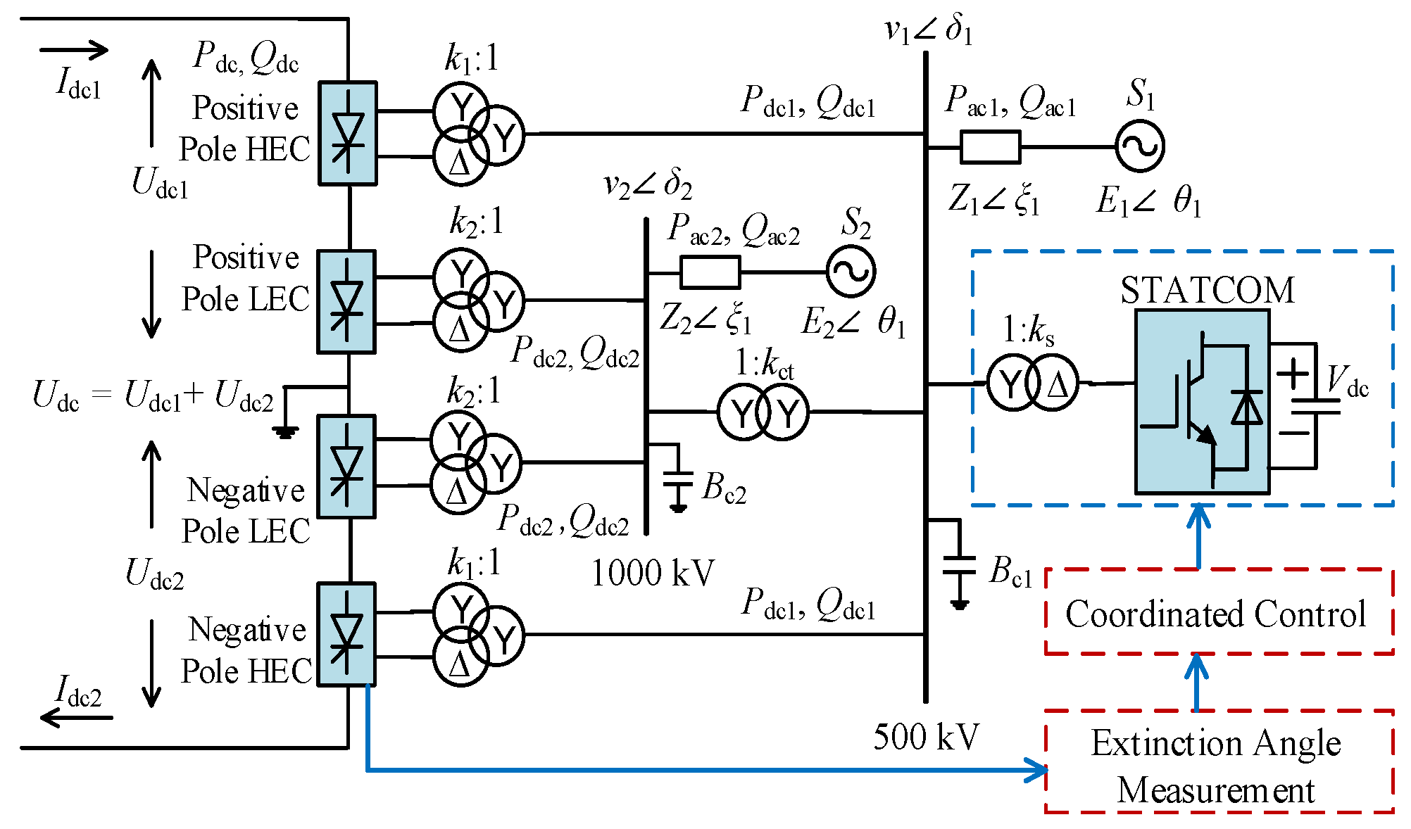
2. UHVDC-HCS Transmission System with STATCOM

Study System

In this paper, a real world bipolar LCC-UHVDC project (Xilingol League to Taizhou city in China) with multiple STATCOMs was considered to analyze the system’s operating characteristics under coordinated control with different STATCOM control modes. The total rated capacity of the UHVDC-HCS system is 10,000 MW with a DC link voltage of ±800 kV. The simplified schematic structure of the UHVDC-HCS system along with a STATCOM on the inverter side is presented in Figure 1. On the inverter side, four twelve pulse LCC converters are attached to different AC voltage sources (i.e., 500 and 1000 kV). The two high end converters (HECs) are connected to the 500 kV bus via a high end converter transformer, whereas the two low end converters (LECs) are linked to the 1000 kV bus through a low end converter transformer. Various shunt capacitors and low and high frequency damping filters are attached on the inverter side AC buses to minimize the harmonics and to fulfill the reactive power requirements of HEC and LEC. The two buses are strongly connected via a coupling transformer with a rated capacity of 3000 MVA. In order to provide surplus reactive power support during transient conditions, four STATCOMs with a capacity of 300 Mvar each are shunt-connected to the 500 kV bus. The reason for connecting multiple STATCOMs is to be compatible with the UHVDC-HCS system, as its rated capacity (10,000 MW) is too large.
In Figure 1, Udc1, Udc2 and Idc1, Idc2 are the DC voltages and DC currents, respectively, Pdc, Pdc1, Pdc2 and Qdc, Qdc1, Qdc2 are the real power and reactive power of the LCC converters, respectively, Pac1, Pac2 and Qac1, Qac2 are the real and reactive power of the AC systems, v1δ1, v2δ2 are the AC bus voltages, E1θ1, E2θ2 and Z1ξ1, Z2ξ2 are electromotive forces and equivalent impedances of the AC sources, respectively, k1, k2, ks, kct and X1, X2, Xs, Xct are turn ratio and leakage reactance of the converters’ transformers, respectively, Rdc1, Rdc2 and Ldc1, Ldc2 are the resistance and inductance of the DC transmission link, respectively. Bc1 and Bc2 are the net admittances of shunt capacitors and AC filters. All other specifications of the UHVDC-HCS system are given in Table A1 of the Appendix A.

3. Basic Control Approach for the Study System

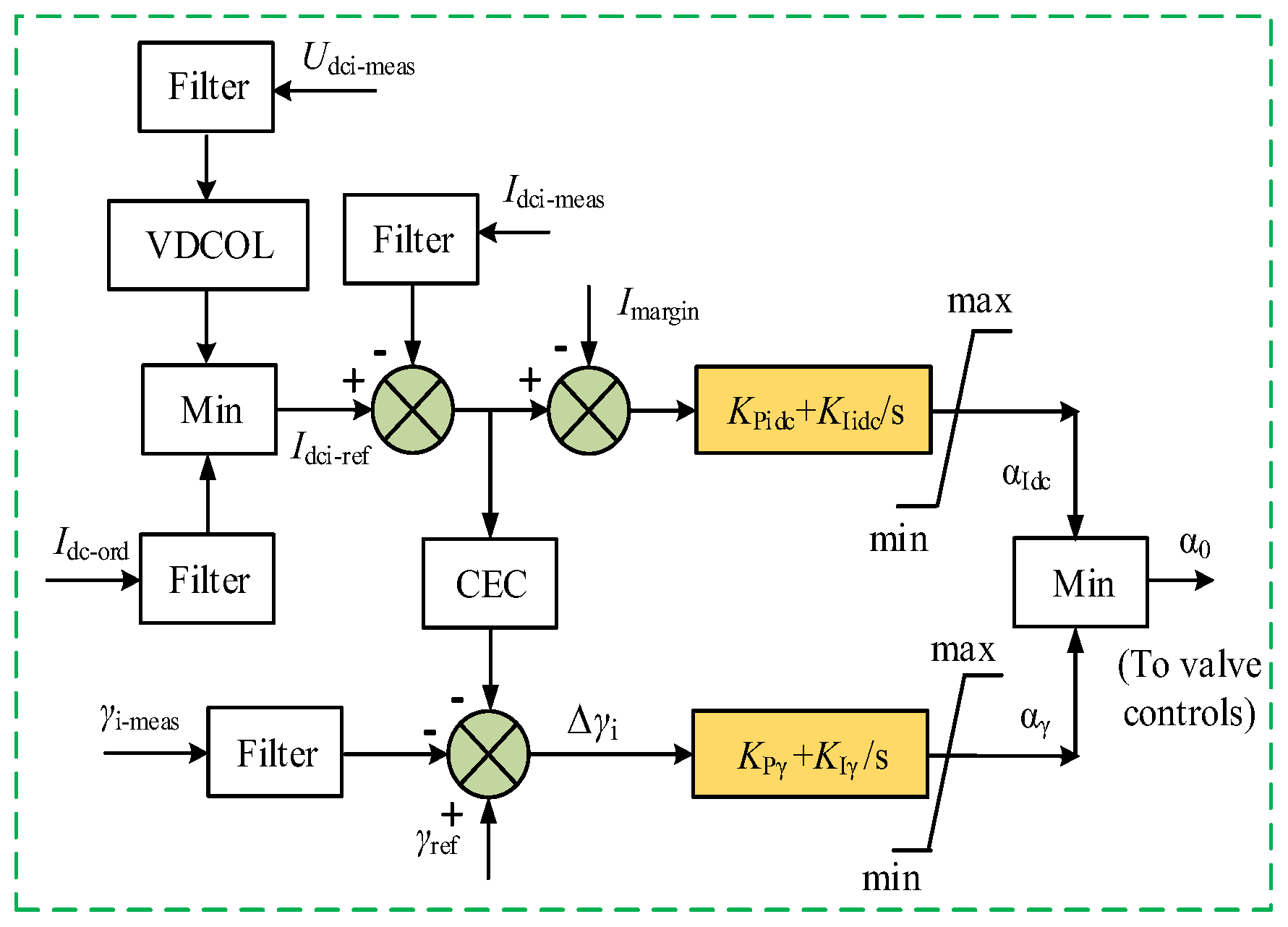
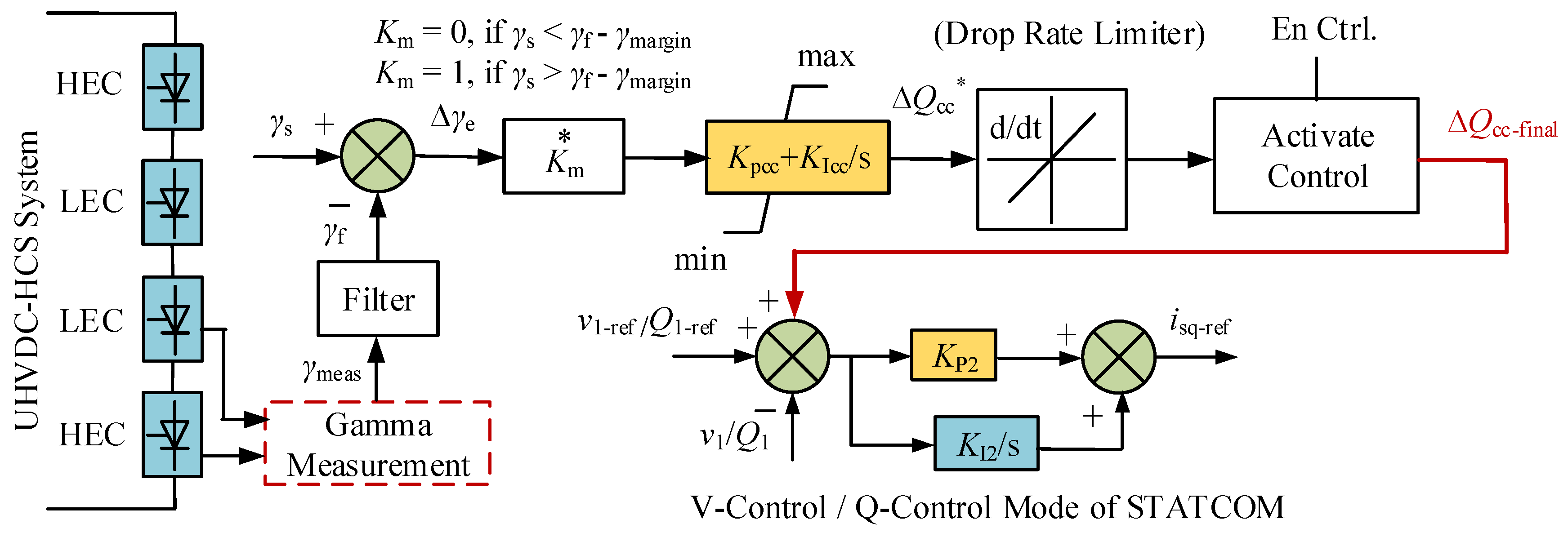
3.1. Control Approach for the UHVDC-HCS System

The extinction angle control and DC current control are implemented at the HEC and LEC of the UHVDC-HCS system as shown in Figure 2. In addition, current error control (CEC) and voltage dependent current order limit (VDCOL) are also used to ensure a smooth transition between different control modes (constant current, constant extinction angle) and to limit the maximum overcurrent, respectively. The VDCOL is used as a backup control mode in the situation where the AC voltage or DC voltage drops to its worst level under different fault conditions. The main application of VDCOL is to decrease the commutation failure probability, to avoid the valve stress caused by sequential occurrence of commutation failure and to support the LCC system to rapidly recover under different faults.

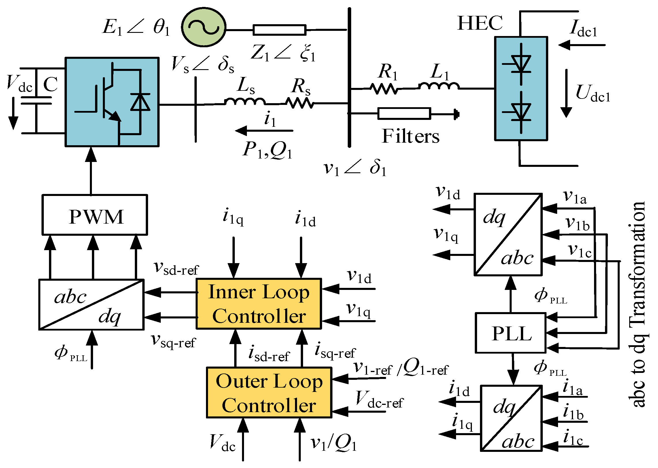
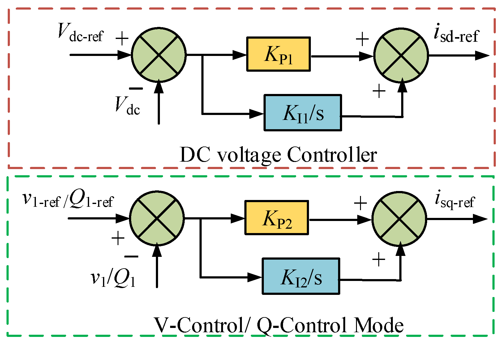
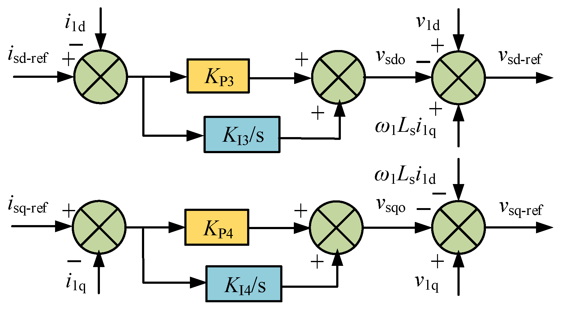
3.2. Control Approach for STATCOM

STATCOM is an advanced static VAr compensator used as shunt connected device to regulate three phase AC voltage of the grid. In this work, the STATCOM is designed as voltage source converter, which consists of a gate-turn off thyristor and a DC bus capacitor. The single line diagram of the STATCOM along with its basic control scheme, linked to the bus 1 of UHVDC system is shown in Figure 3, where Vs is the three phase AC voltage of the STATCOM at the grid side, Vdc is the DC voltage across capacitor, Ls and Rs are the leakage reactance of converter transformer and the reactor connecting STATCOM to bus 1 and i1 is the current injected into the STATCOM from the grid. It is clear from Figure 3 that the STACOM control scheme includes inner and outer loop controllers, Clark-Park’s transformation and pulse width modulation technique (PWM).
The detailed structure of the outer loop controller of the STATCOM is shown in Figure 4, which includes a DC voltage controller and AC voltage/reactive power controller. The main function of the DC voltage controller is to regulate the DC voltage across the capacitor. The AC voltage and reactive power controller can help regulate the AC voltage directly and compensate the reactive power demand of the system, respectively. The outer loop controllers generate reference currents for the inner loop controllers.
The complete structure of inner current control loop is presented in Figure 5, which comprises the reference currents from outer loop controllers, AC side currents and voltages in the dq frame and decoupling terms. The inner current controllers produce reference voltages in the dq frame which are converted to the abc frame using an inverse Park’s transformation. The PWM uses these voltage references to get firing pulses for the converters. The specifications regarding STATCOMs and their contoller’s parameters are summarized in Table A2 of the Appendix A.

4. Coordinated Control between the UHVDC-HCS System and STATCOM

Inspired by [12], this paper presents a coordinated control for UHVDC-HCS systems with multiple STATCOMs to mitigate the commutation failure and improve the fault recovery performance. The block diagram of coordinated control with different control modes (Q-control and V-control) in the outer loop control of STATCOM is shown in Figure 6. It comprises the extinction angle from the high end converter (HEC) or low end converter (LEC), application of a drop rate limiter, PI controller and fault detection enabling function. The extinction angle from converters (HEC or LEC) is selected as the controlling signal for coordinated control, as it does not exhibit too much fluctuation and harmonics during the transient conditions. The extinction angle of HEC of the modeled study system is set at 17°. Considering that extinction angle drops to a low value during transient conditions, the extinction angle (γs) setting value is selected lower than the rated value. The difference between the set extinction angle and the rated extinction angle (γr) is termed the margin extinction angle, which is utilized for enabling output error signals using an internal logic function. With this internal logic function the output error signal and value of Km (in Figure 6) under steady state conditions results in zero, as γs is lower than γr. During transient conditions, the output error value and the value of Km is 1, due to the reason that the rated extinction angle (γr) is smaller than the extinction angle (γs) setting. Two factors are considered to select a value for the margin extinction angle: i) rapid action of coordinated control during transient conditions; ii) no action of coordinated control during steady state conditions. In order to achieve i), a lower value of the margin extinction angle is preferable for sensitivity consideration. To achieve ii), a higher value of the margin extinction angle is preferable for reliability concerns. The acceptable value for the margin extinction angle is 2.5°. The setting extinction angle (γs) value can be computed as γr–2.5°. Table A3 in the Appendix A lists the complete specifications of the coordinate control parameters.
The output error signal (∆γe) generated by comparing the set extinction angle (γs) and rated extinction angle (γr) is then passed to the PI controller. The PI controller processes the error signal and provides the initial compensated reactive power order (∆Qcc*) up to the maximum limit of the reactive power capacity of the STATCOM. The supplied reactive power order is further processed by a drop rate limiter to get the final compensated reactive power order (∆Qcc-final).
The final compensated reactive power order is given to the outer loop controller (Q-control mode or V-control mode) of the STATCOM to provide surplus reactive power to the UHVDC-HCS system, to mitigate the risk of occurrence of commutation failure in HEC and LEC. Under AC fault situations, when ∆Qcc* increases then the drop limiter function does not operate and it operates when the value ∆Qcc* decreases after clearance of AC faults. This strategy can help in reducing the fault recovery time of UHVDC-HCS system under different fault situations.
Two factors are undertaken to select proper value for the drop rate limiter function. The first factor is that too small a value is preferable, which can effectively enable the STATCOM to supply reactive power to the UHVDC-HCS system even during fault recovery instances. The second factor is that too small a value of the drop rate limiter function can result in temporary overvoltage of the 500 kV and 1000 kV AC busbars, by supplying substantial remaining reactive power. Therefore, considering these two mentioned factors, the recommended suitable value for drop rate limiter function in this paper is 0.65–1 p.u./sec.

5. Performance Evaluation of Coordinated Control between the UHVDC-HCS System and STATCOM
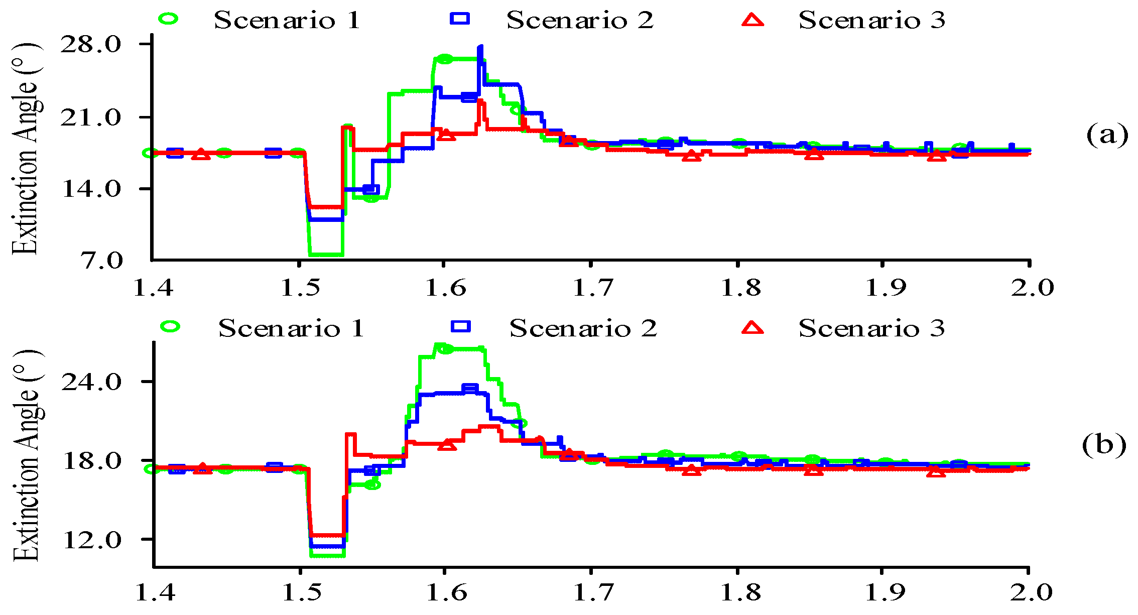
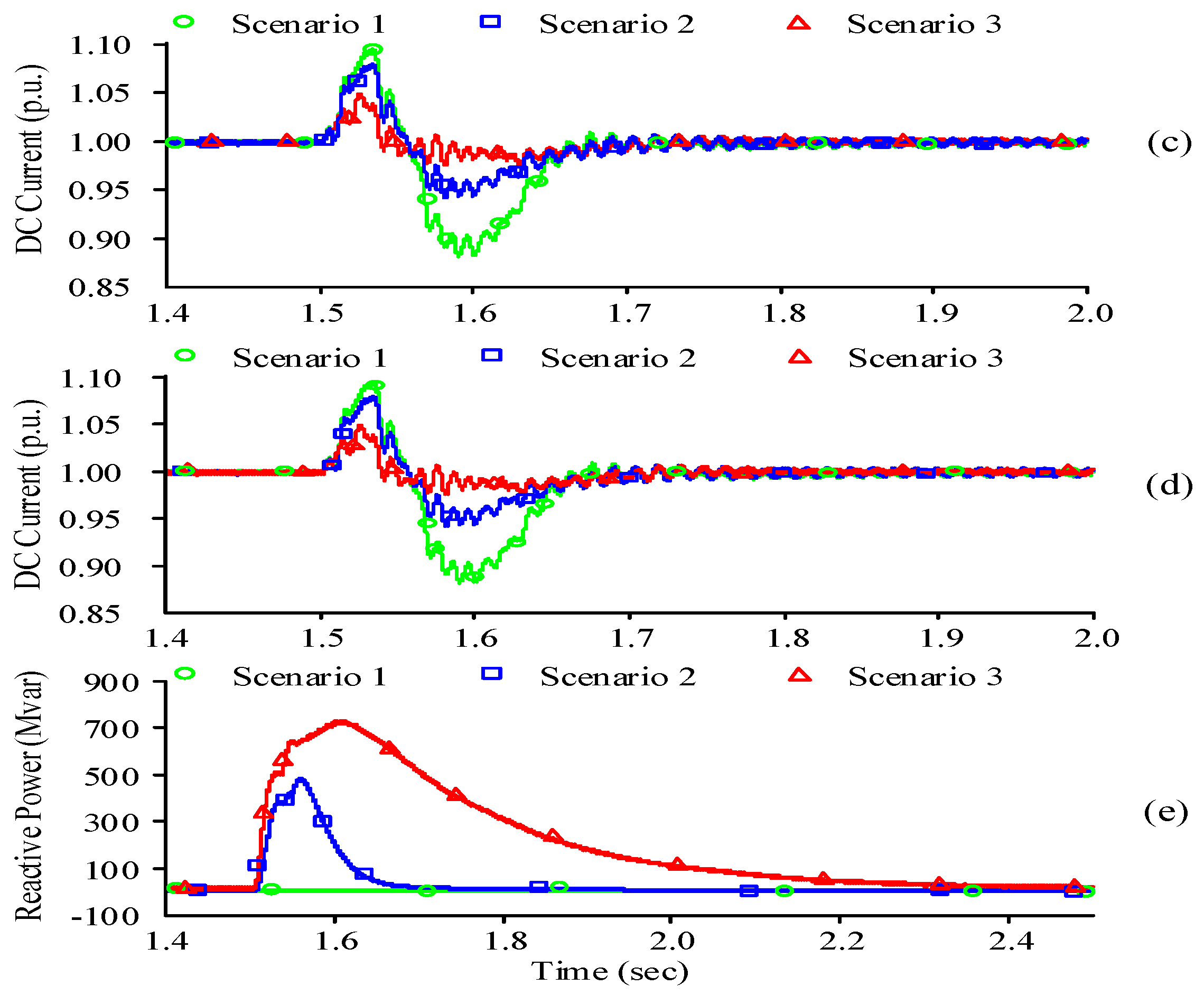
The following three scenarios are considered to evaluate the performance of coordinated control designed for improvement in operational characteristics of an UHVDC-HCS with STATCOM:
Scenario 1:
In this scenario, the analysis is made based on the basic control approach.
Scenario 2:
The analysis is done based on the coordinated control between the UHVDC-HCS system and the STATCOM. The reactive power control (Q-control) mode is adopted in the outer loop control of the STATCOM.
Scenario 3:
The analysis is made based on the coordinated control between the UHVDC-HCS system and the STATCOM. The voltage control (V-control) mode is adopted in the outer loop control of the STATCOM.
The above scenarios mentioned three are investigated by undertaking various tests such as: (i) susceptibility to commutation failure under single and three phase faults; (ii) evaluation of the commutation failure immunity index (CFII) of HEC and LEC under single and three phase faults; (iii) investigation of the commutation failure probability index (CFPI) of HEC and LEC and (iv) fault recovery performance under single and three phase faults.

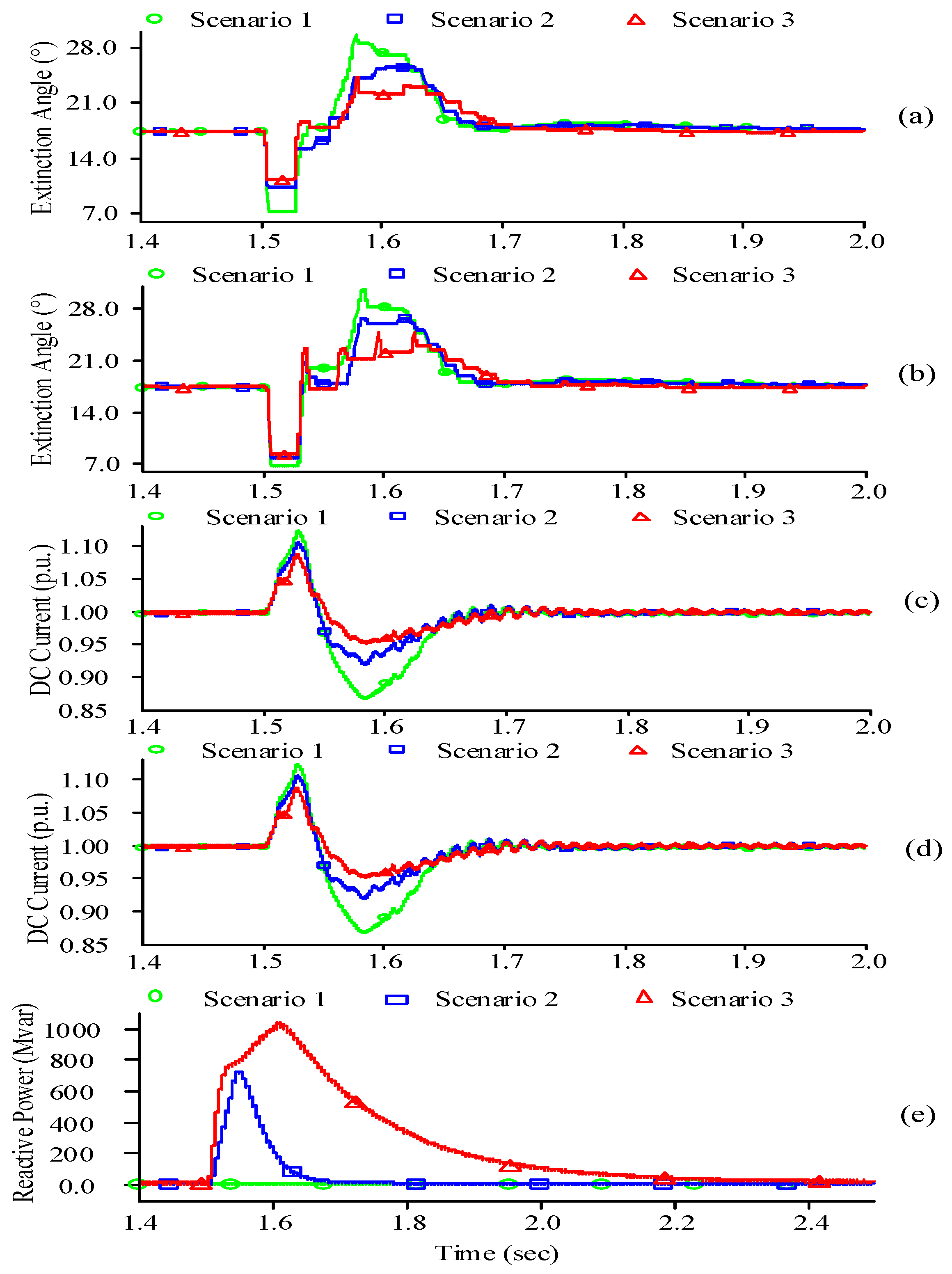
5.1. Susceptibility to Commutation Failure with and without Coordinated Control

Commutation failure occurs in HEC and LEC due to the abrupt increase in DC current and worst AC bus voltage drop, when single and three phase AC faults are applied at either the 500 kV bus or 1000 kV bus. The commutation failure can be evaluated by looking into the extinction angle of HEC and LEC. Due to AC faults, the extinction angle goes to its worst value, which indicates the occurrence of a commutation failure. To get rid of this commutation failure, a higher value of the extinction angle is preferable, but that can result in greater consumption of reactive power and vice versa. In this paper, the setting for the extinction angle is fixed at 17°. There are greater chances of commutation failure if extinction angle becomes lower than 7° [3]. The analytical expression for extinction angle of HEC and LEC are developed as in (1) and (2):
γ HEC = arccos ( 2 X 1 I dc 1 2 U dc 1 + cos ψ 1 )
γ LEC = arccos ( 2 X 2 I dc 2 2 U dc 2 + cos ψ 2 )
where ψ1 (180°–μ1) and ψ2 (180°–μ2) are the advanced triggering angle of the HEC and LEC, respectively. In order to evaluate the susceptibility to commutation failure for the abovementioned scenarios, single and three phase faults are studied in this section.

5.1.1. Single Phase Fault

The single phase fault with inductance level of 0.58 H is applied at the 500 kV bus and the results for different parameters of both HEC and LEC are observed. The fault duration is five cycles (0.1 sec) and it occurs at 1.5 s. The 0.58 H fault inductance level indicates the worst critical fault that does not lead to commutation failure in the HEC and LEC of the UHVDC-HCS system with STATCOM, while using the basic control mechanism.
The simulation graphs for the extinction angle of HEC and LEC, DC current of HEC and LEC and the reactive power supplied by the STATCOM considering three scenarios under single phase fault are shown in Figure 7. It is depicted in Figure 7a that in Scenario 1, the extinction angle of HEC is 7.1°, which is lower than in scenarios 2 and 3. With the presented coordinated control, the extinction angle of HEC in scenarios 2 and 3 increases to 11° and 12.2°, respectively. By comparing scenarios 2 and 3, it is seen that Scenario 3 is relatively better than Scenario 2 in improving the extinction angle of HEC.
Figure 7b shows that the extinction angle of LEC in scenarios 1, 2 and 3 is 10.6°, 11.5° and 12.4°, respectively. Here, the higher value of the extinction angle reveals that a single phase fault applied at the 500 kV bus is not too severe for the 1000 kV bus, because it is not directly applied at the 1000 kV busbar. The slight impact of coordinated control with different control modes (scenarios 2 and 3) on the extinction of LEC is due to two reasons: (i) multiple STATCOMs are not directly linked to the 1000 kV bus and (ii) the leakage reactance of the coupling transformer. It is observed from Figure 7c,d that the DC current in scenarios 2 and 3 is lower than in Scenario 1. The lower DC current under single phase fault conditions indicates that HEC and LEC can sustain the fault without commutation failure. Comparing the three scenarios, coordinated control with V-control mode (Scenario 3) shows better performance in controlling the DC current of the UHVDC system under single phase fault conditions. This is due to the extra reactive power support provided to the UHVDC system during the transient state in Scenario 3 as compared to scenarios 1 and 2 as clearly seen in Figure 7e.

5.1.2. Three Phase Fault

The three phase fault with fault inductance level of 0.69 H is applied to the 500 kV bus at 1.5 s and is cleared after five cycles (0.1 s). Here, 0.69 H is a severe fault inductance level that does not result in occurrence of commutation failure in the HEC and LEC. The simulation graphs for extinction angle and DC current of LCC converters attached to the 500 kV and 1000 kV bus, and the reactive power provided by the STATCOM in three scenarios during a three phase fault are shown in Figure 8. It is obvious from Figure 8a, that the extinction angles of the HEC in scenarios 1, 2 and 3 ares 7.25°, 10.17° and 11.16°, respectively. Similar to the single phase fault, the extinction angle in scenarios 2 and 3 is considerably improved under three phase fault conditions. In addition, Scenario 3 is relatively superior to Scenario 2. It is seen from Figure 8b that in scenarios 2 and 3, the extinction angle of LEC is slightly improved. Figure 8c,d indicate that the DC current in Scenario 1 is 1.14 p.u., in Scenario 2 it is 1.11 p.u. and in Scenario 3 it is 1.09 p.u. This indicates that the presented coordinated control (scenarios 2 and 3) can support the UHVDC-HCS system to limit the DC current under three phase fault conditions.
This can help in decreasing the susceptibility to commutation failure. The reactive power injection into the system in three different scenarios under three phase fault conditions is shown in Figure 8e. It can be seen that the addition of extra reactive power to the 500 kV bus in Scenario 3 is comparatively more than in the other scenarios, which can make it relatively better to improve the transient characteristics of the UHVDC-HCS system by reducing the occurrence of commutation failure in HEC and LEC and by limiting the DC overcurrent.

5.2. Commutation Failure Immunity Index (CFII) with and without Coordinated Control

The effectiveness of the coordinated control with different STATCOM control modes (scenarios 2 and 3) are further investigated by evaluating the well-known index termed as commutation failure immunity index (CFII). It is the ratio of worst fault MVA level that does not cause commutation failure to the total capacity of DC transmitted power [13], analytically expressed as in Equation (3):
CFII i ( % ) = Worst   Fault   MVA P dci × 100 = v i 2 ω L min P dci × 100
where i represents the HEC and LEC linked to the 500 kV and 1000 kV bus, respectively, ω is the electrical angular velocity of AC source, Lmin is the minimum fault inductance level that the HEC and LEC can sustain without facing commutation failure. Equation (3) elaborates that the larger the fault MVA level that does not lead to commutation failure in the HEC and LEC, the higher is the CFII value and greater is the UHVDC system’s strength to reduce the chances of occurrence of commutation failure. The multiple run feature in the PSCAD/EMTDC tool is utilized to evaluate the CFII of the HEC and LEC under single and three fault conditions. The CFIIs of the HEC and LEC are represented by CFIIHEC and CFIILEC respectively, and are used hereafter in this paper. To determine CFIIHEC (CFIILEC), a single phase or three phase fault is applied at the 500 kV (1000 kV) bus. The multiple run method can look for the value of the extinction angle of the HEC and LEC, while continuously changing the fault time and fault inductance level. The fault inductance level is gradually changed from low level to critical fault inductance level. The worst critical fault inductance level that does not cause the occurrence of commutation failure is then selected and is computed in (3) to evaluate the CFIIHEC and CFIILEC. The CFIIHEC and CFIILEC under single phase and three phase faults, while considering the above three scenarios are summarized in Table 1.
It is depicted from Table 1, that CFIIHEC with basic control approach (Scenario 1) under single phase fault is 34.40%, which is increased to 38.99% (Scenario 2) and 41.78% (Scenario 3) by implementing coordinated control between the UHVDC-HCS system and STATCOM. Similarly, the CFIIHEC under three phase fault conditions is also improved in scenarios 2 and 3. However, coordinated control with V-control mode of the STATCOM (Scenario 3) is comparatively better than Scenario 2 in enhancing the CFIIHEC under both AC fault conditions, i.e., single and three phase faults. This is mainly due to improving the extinction angle, providing surplus reactive power and effectively limiting the DC current under different transient conditions as clearly shown in Figure 7 and Figure 8. Considering CFIILEC in all the above scenarios during single and three phase faults at the 1000 kV bus, it is observed that coordinated control with different STATCOM control modes can slightly strengthen the LEC system immunity to commutation failures. Comparing the values of both CFIIHEC and CFIILEC under three phase fault conditions with that of single phase fault conditions, it is depicted that three phase fault is the most severe fault that can result in increased risk of occurrence of commutation failure in the HEC and LEC.

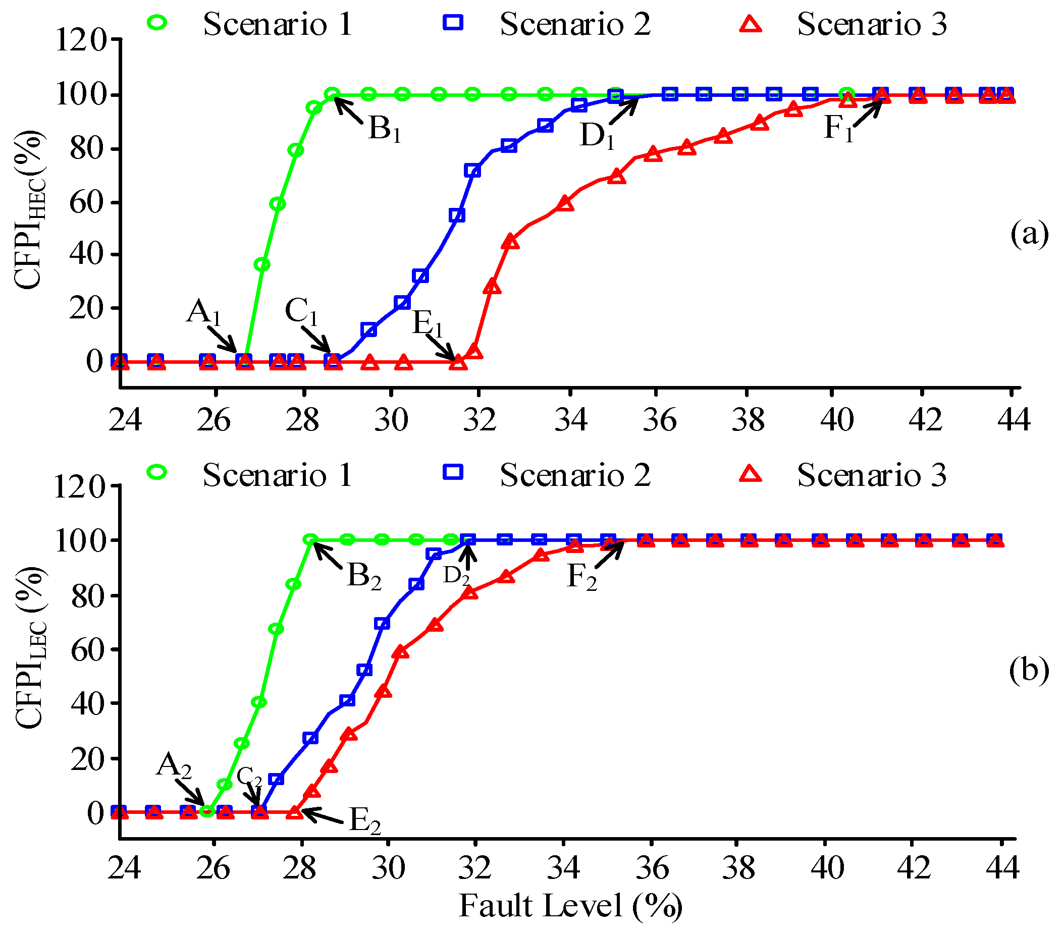
5.3. Commutation Failure Probability Index (CFPI) with and without Coordinated Control

In order to further examine the effectiveness of coordinated control during commutation failure phenomena, another index called commutation failure probability index is presented in this section. It is the ratio of the sum of fault points that can result in commutation failure to the total equivalent fault points considered in one AC cycle [13]. The CFPI is analytically expressed by Equation (4):
CFPI ( % ) = Sum of Fault Points resulting CF Total Fault Points in an AC Cycle × 100
The commutation failure probability index of HEC and LEC is calculated using the multiple run method in PSCAD/EMTDC. Three phase inductive fault is considered for evaluating the CFPI of the HEC and LEC, because it is the most severe fault as compared to capacitive and resistive faults that can lead to commutation failure in UHVDC-HCS systems. As the inverter side of the hierarchical connection mode is comprised of two AC sources with different voltage ratings, therefore the per unit fault level is considered to show that the fault level severity is equal for both buses (500 kV and 1000 kV). Per unit fault level is the ratio of the fault level applied at the AC busbar to the rated DC power capacity of the UHVDC-HCS system. Three phase inductive fault level is applied at the 500 kV and 1000 kV bus in order to determine the CFPI of the HEC (CFPIHEC) and the CFPI of the LEC (CFPILEC) respectively. In case of CFPIHEC, the inductance level is varied from 0.73 H (lowest fault level) to 0.398 H (highest fault level), whereas for CFPILEC, the inductance level is gradually changed from 2.92 H to 1.595 H. A total of 100 fault points are taken in the 20 ms AC cycle duration. The multiple run program can look for the occurrence of commutation failures for a given specified time and fault inductance. The statistics about the occurrence of commutation failure is then computed using Equation (4) to determine CFPIHEC and CFPILEC. In Figure 9, the results for CFPIHEC and CFPILEC of the UHVDC-HCS assuming three scenarios are presented. It is clear from the CFPIHEC and CFPILEC curves that the more severe the fault MVA level, the higher are chances of commutation failure to occur at HEC and LEC.
For Scenario 1, when the fault level is below 26.58% (point A1), there are no chances that commutation failure can occur at the HEC. However, the chances of commutation failure increase with the gradual increase in fault level and when it reaches point B1 (28.8%), the probability of commutation failure is 100%. For Scenario 2 with coordinated control including Q-control mode of the STATCOM, the commutation failure does not occur till the 29.24% fault level applied at the 500 kV bus. However, when the applied fault level reaches to 36% (point D1), the chances of commutation failure at the HEC are increased to 100%. It is depicted from the Scenario 3 curve that commutation failure is not experienced by the HEC at the 31.90% fault level (indicated by point E1) applied at the 500 kV bus, when the UHVDC-HCS system is implemented in addition to coordinated control involving the V-control mode of the STATCOM. However, there are 100% chances of commutation failure when the fault level is above 40.8% (point F1).
Figure 9b shows the commutation failure probability index of LEC for all three scenarios. It is clear from the Scenario 1 curve that commutation failure does not occur in the LEC at 26.11 % fault level (point A2); however, there is 100% commutation failure probability at the applied fault level of 28.4 % (point B2). The Scenario 2 curve indicates that commutation failure is not caused by the fault level of 27.35% (point C2) applied at the 1000 kV bus and there is a 100% chance that an applied fault level greater than 31.8% can cause a commutation failure in the LEC. In Scenario 3, a commutation failure is not experienced by the LEC when the applied fault level at the 1000 kV bus is below 27.83% (point E2); however, there is a 100% chance that the LEC will always experience a commutation failure at 35.6% fault level (point F2). It is thus concluded from the curves of all three scenarios, that scenarios 2 and 3 can support the UHVDC-HCS with STATCOM to reduce the commutation failure probability of HEC and LEC. However Scenario 3 with coordinated control including the V-control mode of the STATCOM is comparatively better than Sscenario 2 in reducing the CFPIHEC and CFPILEC. In addition, it is also observed that with scenarios 2 and 3 the chances of commutation failure in the HEC are greatly reduced compared to the LEC. The reason is that multiple STATCOMs are directly linked to the HEC bus and the leakage reactance of the coupling transformer can also influence the performance of the presented coordinated control.

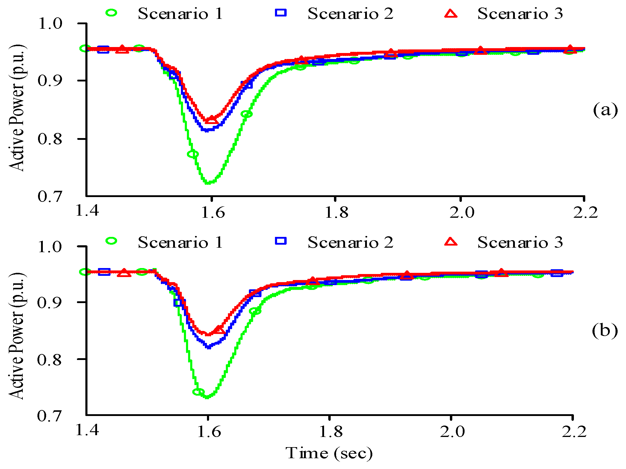
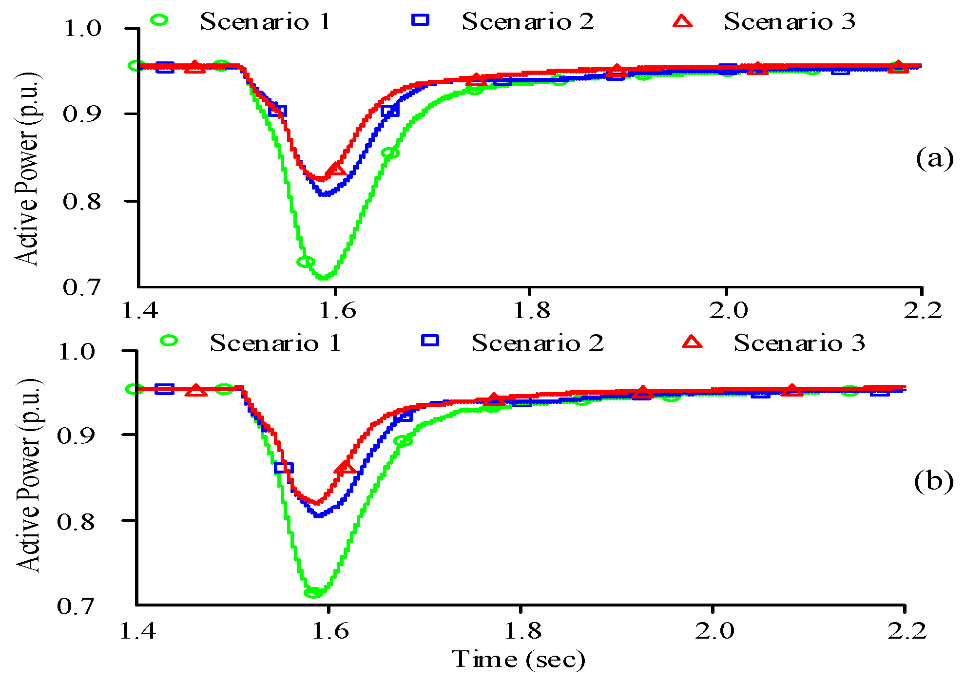
5.4. Fault Recovery Performance with and without Coordinated Control

The UHVDC-HCS system can be totally collapsed and no active power transmission is possible in the case where the AC and DC voltages are not properly restored during various fault conditions. In this paper, fault recovery time is considered as the main matric to quantify the recovery performance of the UHVDC system. The fault recovery time is referred to the time taken by active power to restore to 90% of its prefault value after the clearance of a fault [14]. To analyze the effect of coordinated control on the fault recovery performance of an UHVDC-HCS system, the simulation results for single and three phase faults are discussed in this section.

5.4.1. Single Phase Fault

The single phase fault with 0.50 H inductance is applied to the 500 kV bus at 1.5 s and the fault is cleared after 0.1 s. The simulation curves for active power of the HEC and LEC for three different scenarios are shown in Figure 10. In Scenario 1, the active power drops to 0.67 p.u. and takes 66 ms to recover. The active power drops to 0.817 p.u. and 0.83 p.u. in scenarios 2 and 3, respectively, which indicates a lower drop as compared to Scenario 1. The fault recovery times of the HEC in scenarios 2 and 3 under single phase fault conditions are 37 ms and 26 ms, respectively. It is clear from Figure 10b that fault recovery time of the LEC in scenario 1, 2 and 3 are 64 ms, 35 ms and 25 ms, respectively. This shows that the presented coordinated control with various control modes of STATCOM can also support a 1000 kV AC system to reduce the fault recovery time of the LEC. Comparing the performance of all scenarios in fault recovery improvement of the HEC and LEC, it is thus concluded that Scenario 3 is relatively better than the other two scenarios.

5.4.2. Three Phase Fault

The three phase fault with fault inductance level of 0.60 H is applied at the 500 kV bus. The fault occurs at 1.5 s with duration of 0.1 s. The simulation results for the active power of the HEC and LEC are presented in Figure 11. It is observed from Figure 11a that without coordinated control (Scenario 1), the active power of the HEC drops to a low value as compared to with coordinated control (Scenario 2 and Scenario 3). The fault recovery times of the HEC in scenarios 1, 2 and 3 are 62 ms, 33 ms and 20 ms, respectively, which depicts that the present coordinated control can reduce the fault recovery time under three phase fault conditions. Figure 11b shows that the fault recovery times in scenarios 1, 2 and 3 are 61 ms, 34 ms and 21 ms, respectively. It is thus concluded that the presented coordinated control (scenarios 2 and 3) can effectively reduce the fault recovery time of the HEC and LEC under single and three phase faults at 500 kV bus. In addition, Scenario 3 is comparatively better than Scenario 2. Table 2 summarizes the overall comparative performance evaluation of the three scenarios for the various abovementioned tests.

6. Conclusions

In this paper, the coordinated control is implemented between an ultra-high voltage direct current (UHVDC) transmission system under a hierarchical connection scheme (HCS) with multiple STATCOMs on the inverter side. The specific purpose of coordinated control is to mitigate the occurrence of cascaded commutation failure in the HEC and LEC and to decrease the fault recovery time during single and three phase AC faults. The coordinated control is modelled in PSCAD/EMTDC. The robustness and effectiveness of coordinated control on the operating characteristics of the UHVDC-HCS system are comprehensively investigated by comparing the dynamic performance of different control modes (Q-control and V-control) of the STATCOM. Moreover, the impact of coordinated control on the commutation failure immunity index (CFII) and commutation failure probability index (CFPI) of the HEC and LEC is analyzed in detail. The analysis shows that the presented coordinated control can improve the operating characteristics of an UHVDC-HCS system by decreasing the susceptibility to commutation failure, increasing the commutation failure immunity index (CFII) of the HEC and LEC, improving the commutation failure probability index of HEC and LEC and effectively decreasing the fault recovery time under single and three phase AC fault conditions. Comparing the Q-control and V-control modes of the STATCOM, it is seen that coordinated control with V-control mode is relatively more effective in enhancing the operating characteristics of an UHVDC-HCS system under various disturbances.

Author Contributions

The authors equally contributed to this research work.

Acknowledgments

The authors acknowledge the financial support from National Natural Science Foundation of China under Grant 51877077.

Conflicts of Interest

The authors declare no conflicts of interest.

Appendix A

Table A1. Parameter Specifications of the UHVDC-HCS System.
ParametersValue
Rated DC transmission capacity10,000 MW
Rated DC voltage±800 kV
Short circuit ratio of AC systemSCR1 = 2.5 SCR2 = 2.5
AC voltage systemE1 = 544 kV E2 = 1055 kV
AC system’s impedanceZ1ξ1 = 22∠85° Ω; Z2ξ2 = 88.2 ∠75° Ω
Coupling transformer’s capacity3000.0 MVA
Coupling transformer’s turn ratio1050/525
Coupling transformer’s leakage reactance0.18 pu
Converter transformer’s capacity1466.1 MVA
Converter transformer’s turn ratio525/165.8 1050/165.8
Converter transformer’s leakage reactance0.2 pu
Table A2. Parameter Specifications of the STATCOM.
ParametersValue
Capacity of STATCOM4 × 300 Mvar
Transformer’s turn ratio525/13.8
Transformer’s leakage reactance0.18 pu
DC voltage controllerKP1 = 10, KI1 = 0.01
AC voltage controller or
Reactive power controller
KP2 = 14, KI2 = 0.01
Inner i1d controllerKP3 = 15, KI3 = 0.001
Inner i1q controllerKP4 = 15, KI4 = 0.001
Table A3. Parameter Specifications of Coordinated Control.
System ParametersValue
Rated value of extinction angleγf = 17°
Setting value of extinction angleγs = 14.5°
Value of drop rate limiter function0.80 p.u./sec
PI controller’s constantsKpcc = 2.15, KIcc = 0.01
Maximum limit of PI controller1.0 p.u.
Minimum limit of PI controller−1.0 p.u.

References

  1. Tang, Y.; Li, F.; Wang, Q.; Chen, B.; Jiang, Y.; Guo, X. Power stability analysis of UHVDC systems hierarchically connected to AC systems. Electr. Power Syst. Res. 2017, 163, 715–724. [Google Scholar] [CrossRef]
  2. Liu, Z.; Qin, X.; Zhao, L.; Zhao, Q. Study on the application of UHVDC hierarchical connection mode to multi-infeed HVDC system. Proc. CSEE 2013, 33, 1–7. [Google Scholar]
  3. Sun, J.; Fu, R.; Tang, Y.; Sun, W.; Huang, X. Analysis on the operating characteristic of UHVDC new hierarchical connection mode to AC system. J. Power Technol. 2016, 96, 229–237. [Google Scholar]
  4. Li, S.; Wu, Z.; Huang, J. Power flow modelling to UHVDC line and its hierarchical connection mode. Proc. IET Gen. Transm. Distrib. 2018, 12, 1554–1564. [Google Scholar] [CrossRef]
  5. Zhang, Y.; Gole, A.M. Comparison of the transient performance of STATCOM and Synchronous condenser at HVDC converter stations. In Proceedings of the 11th IET International Conference on AC and DC Power Transmission, Birmingham, UK, 10–12 February 2015; pp. 1–8. [Google Scholar]
  6. Zhuang, Y.; Menzies, R.W.; Nayak, O.B.; Turanli, H.M. Dynamic performance of a STATCON at an HVDC inverter feeding a very weak AC system. IEEE Trans. Power Deliv. 1996, 11, 958–964. [Google Scholar] [CrossRef]
  7. Nayak, O.B.; Gole, A.M.; Chapman, D.G.; Davies, J.B. Dynamic performance of static and synchronous compensators at an HVDC inverter bus in a very weak AC system. IEEE Trans. Power Syst. 1994, 9, 1350–1358. [Google Scholar] [CrossRef]
  8. Andersen, B.R.; Xu, L. Hybrid HVDC system for power transmission to island networks. IEEE Trans. Power Deliv. 2004, 19, 1884–1890. [Google Scholar] [CrossRef]
  9. Zhibing, W.; Yang, X.; Xitian, W. Coordinated control strategy of reactive power for large-scale wind power transmission by LCC-HVDC links. J. Eng. 2017, 13, 1082–1086. [Google Scholar] [CrossRef]
  10. Bidadfar, A.; Abedi, M.; Karrari, M.; Gharehpetian, G.B.; Tavana, S.N. Passive AC network supplying the integration of CCC-HVDC and VSC-HVDC systems. Turk. J. Electr. Eng. Comput. Sci. 2014, 22, 353–362. [Google Scholar] [CrossRef]
  11. Guo, C.; Zhao, C. Supply of an entirely passive AC network through a double-infeed HVDC system. IEEE Tran. Power Electr. 2010, 25, 2835–2841. [Google Scholar]
  12. Guo, C.; Yang, Z.; Ning, L.; Zhao, C. A novel coordinated control approach for commutation failure mitigation in hybrid parallel-HVDC system with MMC-HVDC and LCC-HVDC. Electr. Power Comp. Syst. 2017, 45, 1773–1782. [Google Scholar] [CrossRef]
  13. Rahimi, E.; Gole, A.M.; Davies, J.B.; Fernando, I.T.; Kent, K.L. Commutation failure analysis in multi-infeed HVDC systems. IEEE Trans. Power Deliv. 2011, 26, 378–384. [Google Scholar] [CrossRef]
  14. Guo, C.; Zhang, Y.; Gole, A.M.; Zhao, C. Analysis of dual-infeed HVDC with LCC-HVDC and VSC-HVDC. IEEE Trans. Power Deliv. 2012, 27, 1529–1537. [Google Scholar] [CrossRef]
Figure 1. The basic structure of the inverter ‘side of the UHVDC-HCS with STATCOM system.
Energies 12 00945 g001
Figure 2. Block diagram of the inverter ‘side control of the UHVDC-HCS system.
Energies 12 00945 g002
Figure 3. Single line diagram of the STATCOM with its basic control approach.
Energies 12 00945 g003
Figure 4. Outer loop controller of the STATCOM power controller.
Energies 12 00945 g004
Figure 5. Inner current controller loop of the STATCOM.
Energies 12 00945 g005
Figure 6. Block diagram for coordinated control between the UHVDC-HCS system and STATCOM.
Energies 12 00945 g006
Figure 7. Simulation results for single phase fault. (a) Extinction angle of the HEC (b) Extinction angle of the LEC (c) DC current of the HEC (d) DC current of the LEC (e) Reactive power of the STATCOM.
Energies 12 00945 g007aEnergies 12 00945 g007b
Figure 8. Simulation results for a three phase fault. (a) Extinction angle of the HEC; (b) Extinction angle of the LEC; (c) DC current of the HEC; (d) DC current of the LEC; (e) Reactive power of the STATCOM.
Energies 12 00945 g008
Figure 9. CFPIHEC and CFPILEC values for three scenarios under three phase fault conditions
Energies 12 00945 g009
Figure 10. Active power of the UHVDC-HCS system with and without coordinated control under single phase fault conditions: (a) HEC; (b) LEC
Energies 12 00945 g010
Figure 11. Active power of the UHVDC-HCS system with and without STATCOM coordinated control under three phase fault conditions: (a) HEC (b) LEC.
Energies 12 00945 g011
Table 1. CFIIHEC and CFIILEC Values for Three Scenarios under Single and Three Phase Fault Conditions.
ScenarioSingle Phase FaultThree Phase Fault
CFIIHEC (%)CFIILEC (%)CFIIHEC (%)CFIILEC (%)
Scenario 134.4033.9226.5826.11
Scenario 238.9934.8729.2427.35
Scenario 341.7836.1631.9027.83
Table 2. Summary of the Operating Characteristics of UHVDC-HCS System under Various Tests Conducted for three Scenarios.
ScenariosVarious Tests Conducted
Single Phase FaultThree Phase Fault
Susceptibility to Commutation FailureCFII (%)Fault Recovery Time (msec)Susceptibility to Commutation FailureCFII (%)Fault Recovery Time (msec)CFPI (%)
Scenario 1HighLowLongerHighLowLongerHigh
Scenario 2ModerateModerateShorterModerateModerateShorterModerate
Scenario 3LowHighVery shortLowHighVery shortLow

