Article

Research on Distribution and Shielding of Spatial Magnetic Field of a DC Air Core Smoothing Reactor

1
School of Electrical Engineering, Shandong University, Jinan 250061, China
2
Shandong University Library, Shandong University, Jinan 250061, China
3
Shandong Electrician Electric Group Co., Ltd., Jinan 250022, China
4
State Grid Shandong Electric Power Maintenance Company, Jinan 250118, China
*
Author to whom correspondence should be addressed.
Energies 2019, 12(5), 937; https://doi.org/10.3390/en12050937
Submission received: 31 January 2019 / Revised: 25 February 2019 / Accepted: 27 February 2019 / Published: 11 March 2019
(This article belongs to the Section F: Electrical Engineering)

Abstract

:
With the rapid development of ultra-high-voltage direct current (UHVDC) transmission, air core smoothing reactors have become the main source of electromagnetic contamination in converter substations. The actual magnetic field distribution was obtained by measuring the magnetic induction intensity of the polar busbar smoothing reactor under full load operation condition of the Jiaodong ±660 kV converter substation. A method combined with the measured data to eliminate the influence of the geomagnetic field is proposed. The magnetic field distribution model of the smoothing reactor is established and the rationality and validity of the model for magnetic field distribution is verified. Some magnetic shielding measures are proposed and their effectiveness is verified by simulation and small-scale experiments.

1. Introduction

Reactors are widely used in power systems as inductive components, which are responsible for reactive power compensation, current limitation, current stabilization, filtering, and phase shift. They are important power equipment in power transmission engineering [1,2,3,4]. Reactors can be divided into iron core reactors and air core reactors, according to their different magnetic structures. Air is used as magnetic media in air core reactors, so the magnetic flux density around the space is larger than in iron core reactors. Smoothing reactors are one of the air core reactors in high-voltage direct current (HVDC) transmission engineering. They are used to reduce harmonic current, limit fault current, and prevent commutation failure, and for current interruption in light load operation. However, smoothing reactors are the main strong magnetic field sources in converter stations because of seriously magnetic flux leakage [5,6,7,8]. With the improvement of the power grid level and people’s safety awareness of the electromagnetic environment, it is necessary that the spatial magnetic field of smoothing reactors are studied and magnetic shielding measures are proposed.
Study on the magnetic field of air core reactors is mainly concentrated in the area of AC air core reactors. The scaling rules and the equivalency of the scaled experimentation have been verified [9,10,11,12]. The magnetic field distribution of the air core reactor in a substation has been tested and numerically calculated [13]. The calculated value was in good agreement with the measured value. The influences of the installation height and phase-to-phase distance of the three-phase air core reactor on the distribution of the surrounding power frequency electromagnetic field has been analyzed by simulation [14]. The eddy current loss and heating of metal equipment around the air core reactor under power frequency have been analyzed by test and measurement [15,16]. On the basis of the magnetic field distribution of the air core reactor, the magnetic field shielding measures have been studied and the shielding effects of different shielding body erection schemes compared [17].
There is also some research on the magnetic field distribution of DC air core reactors. The equivalent circuit model of the dry-type smoothing reactor is established. The distribution of the stray magnetic field of the winding, current, and inductance of the parallel branch are calculated; the test is not carried out but it is important [18]. The magnetic field distribution of the dry-type smoothing reactor is measured in [19,20], but its measurement range is limited to one side of the pole bus-level smoothing reactor, and the influence of the geomagnetic field and full-load operation on the measurement results is not considered.
Based on the above research problems, in this paper, the spatial magnetic induction intensity distribution around the south, north, and west sides of the DC smoothing reactor of the ±660 kV converter substation in Jiaodong is measured. The influence of the geomagnetic field is analyzed and the measured data is compared with the simulation results. In order to reduce the spatial magnetic field around the smoothing reactor, magnetic shielding measures are proposed. By comparing the shielding effects of different materials, sizes, and positions, an optimal shielding erection scheme is proposed. Shielding effectiveness of the reactor is verified by a scaled model and basis for the improvement of the spatial magnetic field of the DC smoothing reactor is provided.

2. Magnetic Field Distribution Measurement of Smoothing Reactor

2.1. Conditions and Instruments

In this paper, the Pole I Pole busbar reactor of the Jiaodong ±660 kV converter station is studied. The Pole II Pole busbar reactor is located about 200 m north of the Pole I Pole busbar reactor and the pole II valve hall on the east. The parameters of the reactor and the size of the fence are the same as those of the pole I. Due to the long distance between the two reactors, they have no effect on each other during operation. The converter station has a bipolar rated capacity of 4000 MW, a rated voltage of ±660 kV, a rated current of 3030 A, and a bipolar full load operation. Four smoothing reactors are installed at each pole of the station, including one-pole busbars and three neutral wires. Due to the bipolar symmetric operation, there is no current flowing through the neutral line, so it can be considered that the neutral line reactor does not affect the magnetic field distribution of the pole bus reactor. The rated inductance of a single unit is 75 mH, and the total inductance is 300 mH. The model of the pole busbar reactor is PKK-660-3030-75G, manufactured by Beijing Electric Power Equipment Factory, with rated voltage +660 KV, rated current 3030 A. The reactor is installed on the insulation pillar with air self-cooling and outdoor operation. The bottom of the body is 13.42 m away from the ground, as shown in Figure 1.
The test was carried out with a GMR50 handheld high-precision low-intensity magnetic field gaussmeter manufactured by Coliy Technology GmbH. The geomagnetic field, the workpiece remanence, and the ambient magnetic field can be accurately measured by the new GMR weak magnetic field sensor. The accuracy of GMR50 is 1% of reading and 0.01 μT of resolution, 0–4.5 mT of magnetic field measurement range, and DC 100 Hz of frequency response range, which can be easily carried and operated to meet the test needs. The test temperature is 20 °C, relative humidity is 48%, altitude is 23 m, north wind is level 2, and there is no rainfall.

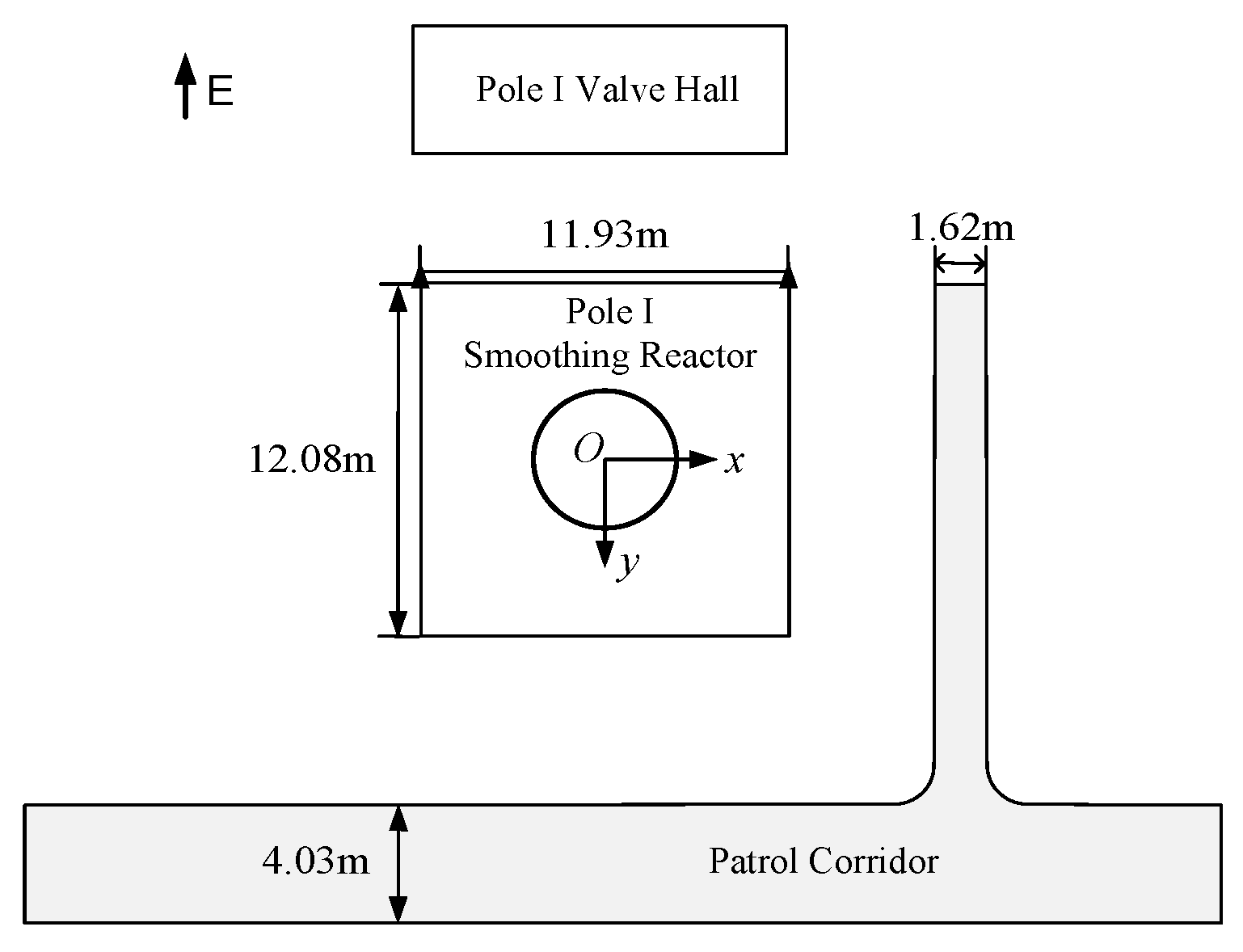
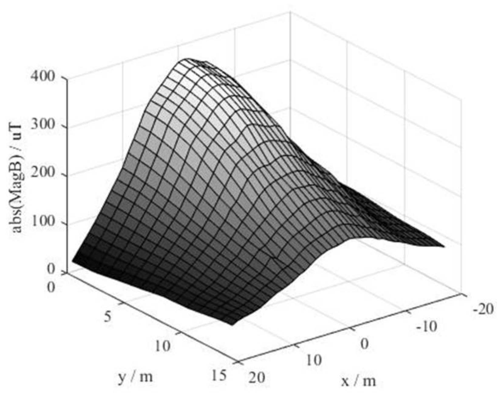
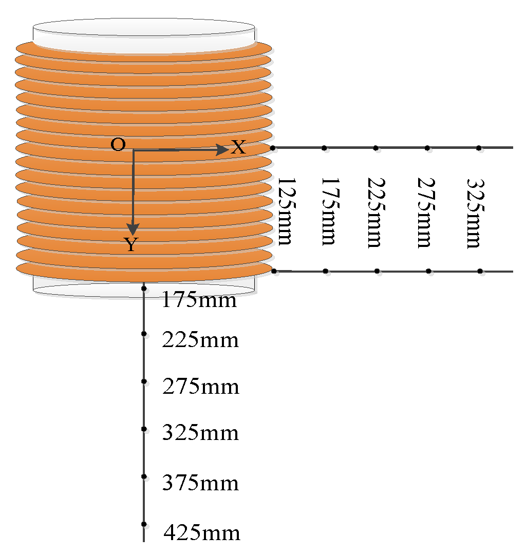
2.2. Measurement Point Setting and Magnetic Field Distribution Measurement

The smoothing reactor consists of 20 layers of coils with a coil height of 4200 mm, an inner diameter of 1882 mm, and an outer diameter of 4228 mm. The coil dimensions of each layer are known and the site layout of the smoothing reactor is shown in Figure 2. The outer fence size is 12.08 m × 11.93 m. There is a corridor with a width of 1.62 m at 4 m outside the fence on the south, another 6 m corridor at the west of the fence with a width of 4.03 m, and to the east is the pole I valve hall. The center of the reactor is taken as the origin, and a coordinate system as shown in Figure 2 is established.
According to the site conditions, the magnetic field measurement points are reasonably arranged, and the magnetic induction strengths of the south, north, and west sides of the DC smoothing reactor are respectively measured. The test area is 40 m × 14 m (x = −20–20 m, y = 0–14 m) and sampling points are set every 2 m along x and y. According to the evaluation criteria for electromagnetic environment of an HVDC converter station [21], the height of the measuring point from the ground is 1.5 m. The magnetic induction intensity sampling data at 1.5 m above the ground of each sampling point is shown in Table 1.
It can be seen from Table 1 that the maximum magnetic induction intensity at 1.5 m above the ground outside the pole fence is 353 μT, which is much smaller than the public commission issued by the International Commission on Non-Ionizing Radiation Protection. The static magnetic field reference limit of day radiation is 400 mT [22,23,24,25].
The sampled data is drawn into a surface map, and the regions that cannot be tested are appropriately interpolated. According to the coordinate system in Figure 2, the magnetic field distribution map shown in Figure 3 is obtained. It can be observed from the measurement results that the magnetic induction of the north of the pole I reactor is significantly larger than that of the south, which is mainly due to the influence of the geomagnetic field. In addition, pole I is relatively further from the reactor on the south due to the influence of other equipment, and the magnetic induction near the central axis of the reactor is smaller than in the west. Due to the influence of the geomagnetic field, great differences exist between the calculated value and the measured value. The influence of the geomagnetic field is analyzed below.

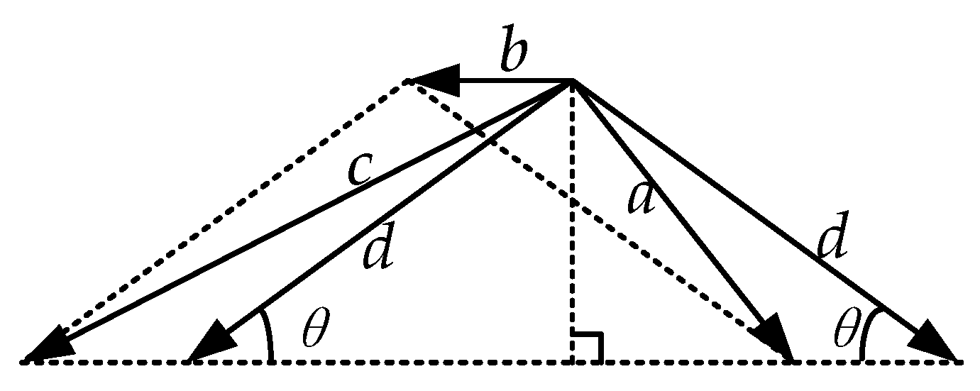
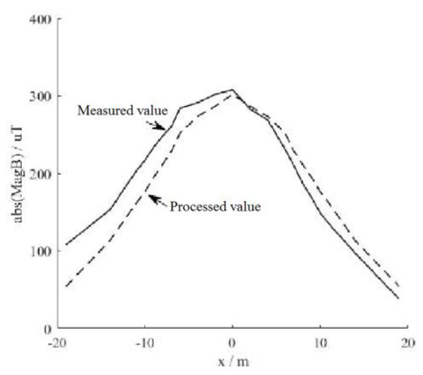
2.3. Geomagnetic Field Correction

The magnetic induction intensity distribution of the smoothing reactor should theoretically be center symmetrical. Due to the influence of the geomagnetic field in the environment, the measured distribution of the magnetic induction intensity has shifted in the actual measurement. In order to eliminate the influence of the geomagnetic field, the (1) is obtained by the laws of vector algebra shown in Figure 4, where a and c are the original measured values of two symmetrical sampling points in the north–south direction of which the reactor is the center, b is the magnitude of the geomagnetic field which is 60 μT along the −x axis [21,26,27], and d is the magnetic induction after eliminating the influence of the geomagnetic field.
c 2 = b 2 + d 2 + 2 b d × cos q a 2 = b 2 + d 2 2 b d × cos q
From (1),
d = a 2 + c 2 2 b 2
The measurement data in Figure 3 is used to eliminate the influence of the geomagnetic field according to the above analysis. The magnetic induction intensity processing value after the elimination of the geomagnetic field is obtained in Table 2.
The data in Table 2 is plotted as a curve, as shown in Figure 5.

3. Modeling of Magnetic Field Distribution of DC Smoothing Reactor

In this paper, the 3D magnetic field of the reactor is calculated by the method of edge-node finite element coupling. In the current-carrying zone and the air of its multiple connected holes, the magnetic induction variable is discretized by edge element, but the scalar magnetic position variable is discretized by node element in the external non-current-carrying zone. There are few edge finite element variables to be used and inhomogeneous medium can be handled. A symmetric finite element stiffness matrix can be formed after coupling the magnetic induction intensity and the scalar magnetic position according to the boundary conditions [28].
Since the structure of the smoothing reactor is complicated, and the non-bearing current structure has little influence on the magnetic field, the modeling is simplified as follows: Ignore the structure of insulation, stays, rain cover, etc., and only consider the coil carrying the current and the star bracket; assume that each envelope has the same current density; ignore the effect of the geomagnetic conductivity.

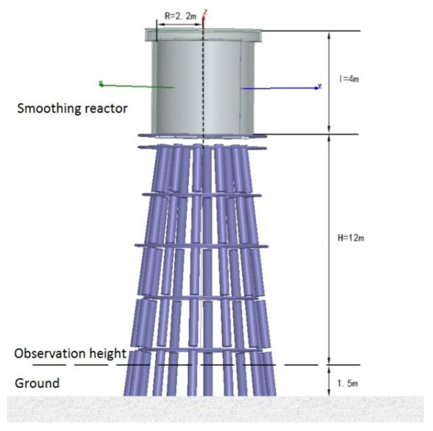
3.1. Establishment of Simulation Model

According to the actual engineering case, the simulation of the magnetic shielding air core reactor is performed on the Ansoft Maxwell software platform (Ansoft Maxwell15.0, Ansoft Company, Pittsburgh, Pennsylvania, USA). The simulation model of the air core reactor is shown in Figure 6. The reactor height l is 4 m, the radius R is 2.2 m, the observation height is 1.5 m from the ground, and the distance between the erection position and the observation height H is 12 m.

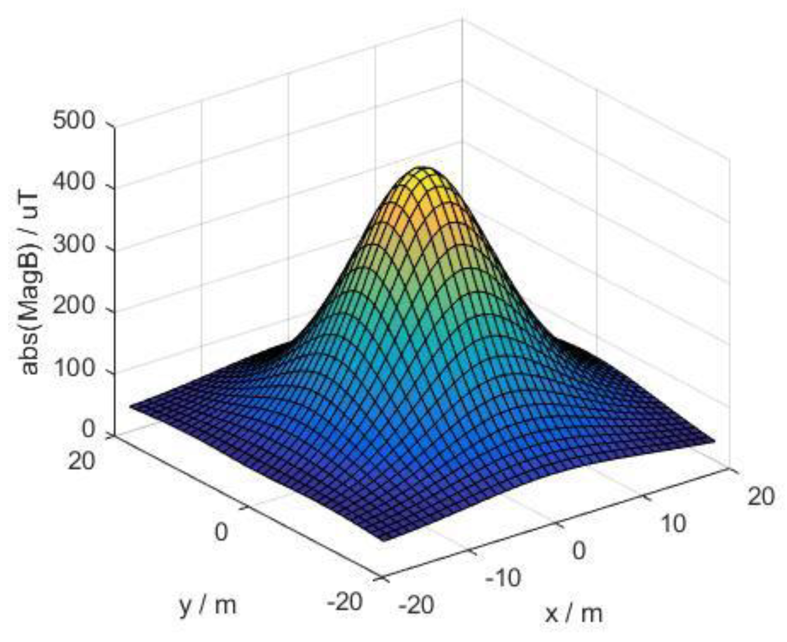
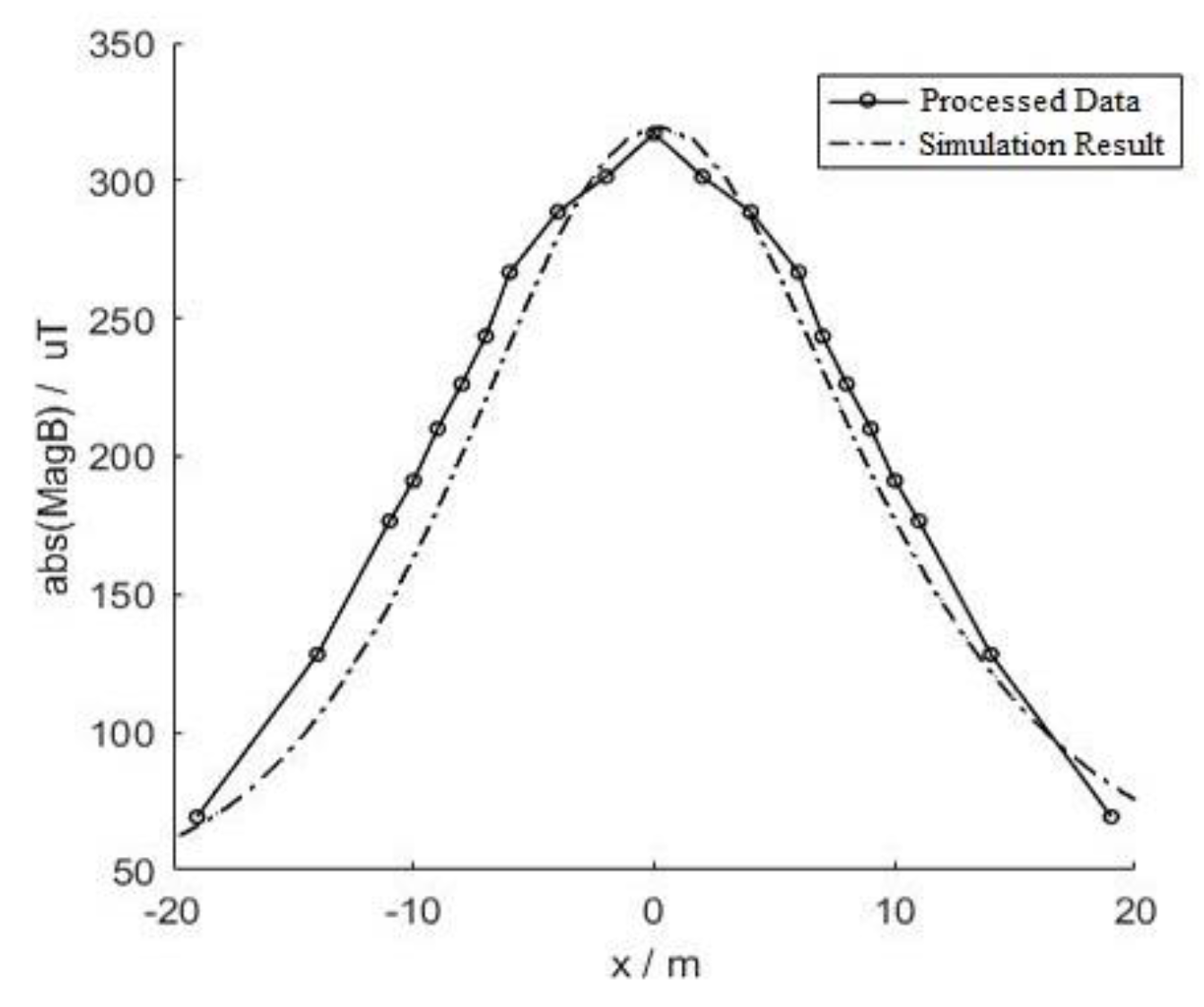
3.2. Calculation of Magnetic Field Distribution

According to the above model, the spatial magnetic field distribution of the DC smoothing reactor is calculated. The maximum magnetic induction of the outer surface of the reactor is 58 mT, which is located at the center of the bottom surface of the reactor. The maximum magnetic induction of the outer surface of the reactor is 12 mT, which is half of the height of the reactor.
In order to avoid the influence of the strong spatial magnetic field of the smoothing reactor on the human and the equipment, it is generally installed on the insulating pillar of ten meters. The calculation results of the magnetic induction distribution at 1.5 m above the ground is shown in Figure 7. The magnetic induction value at this height is used as the evaluation standard for the electromagnetic environment in the industry standards for HVDC converter stations [21]. The maximum magnetic induction on the horizontal plane located directly below the reactor is 430 μT. Further away from the central axis of the reactor, the magnetic induction is lower, and is symmetrically distributed about the central axis of the reactor. This is far less than the static magnetic field reference limit of 400 mT for public all-day radiation, issued by the International Commission on Non-Ionizing Radiation Protection [27].
As can be seen from Table 1 in Section 2.2, the maximum magnetic induction intensity at 1.5 m above the ground outside the pole fence is 353 μT, which is similar to the calculated value of 334 μT. In actual measurement, the magnetic induction intensity of the north of the pole I reactor is significantly larger than the symmetrical position of the south side. This is mainly the influence of the geomagnetic field, which can be eliminated according to the analysis and processing of the geomagnetic fields in Section 2.3.
For a more intuitive analysis, the corrected value of the magnetic induction is plotted as a curve and compared with the calculated result in Figure 8.
It can be seen from the above analysis that the simulation results of the air core reactor model are basically consistent with the results corrected by the geomagnetic field. The correctness of the simulation model is verified and the simulation model can be used to simulate the magnetic field.

4. Magnetic Field Shielding of DC Smoothing Reactor

The stray magnetic field around the DC smoothing reactor is the main source of magnetic field pollution at the converter station. In order to prevent its impact on personal safety and the operation of equipment, the smoothing reactor is generally installed on a high insulating pillar, which requires high installation cost and seismic performance [28]. In response to this problem, magnetic field shielding measures for the DC smoothing reactor are proposed. The spatial magnetic induction around the DC smoothing reactor is reduced by erecting the shield, which has different shielding effects with different material, size and installation position. After the simulation model is established and correctness is verified, the magnetic field shielding effect is simulated for the above different situations.

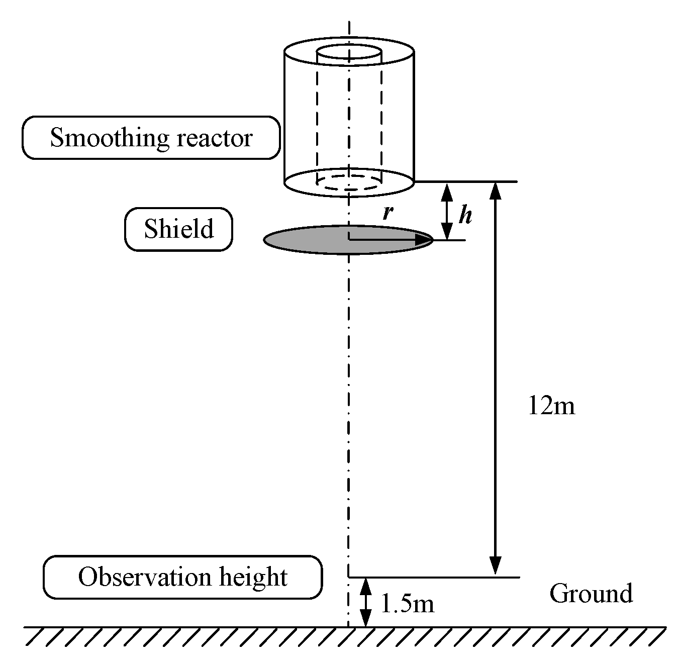
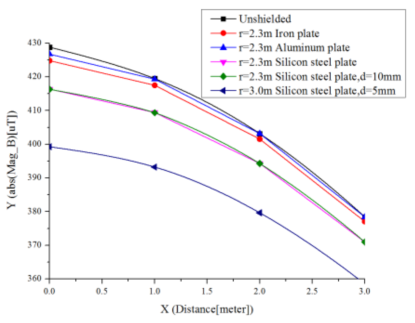
4.1. Shield Plate Under The Reactor

Magnetic field shielding materials have high conductivity and high magnetic permeability. The high-conductivity material is used as a shield to cancel the external magnetic field by the induced eddy current magnetic field generated by the external high-frequency magnetic field. The high magnetic permeability material is made into shield so that a low reluctance path is provided for the magnetic field, and the magnetic lines are confined inside the shield to prevent diffusion into the space. The higher the magnetic permeability of the shield and the thicker the wall layer, the more obvious the magnetic shunting effect and the better the magnetic shielding effect.
A reactor model is established as shown in Figure 6—the circular shielding plates are horizontally installed directly below the reactor, and different materials and sizes are used. The radius is r, the thickness is d, and the vertical distance from the bottom of the reactor is h, as shown in Figure 9; the material type and size parameters of the shielding body are shown in Table 3.
Figure 10 is a magnetic induction intensity distribution curve along the x axis direction 1.5 m from the ground directly below the reactor. It can be seen that high magnetic permeability materials such as iron and silicon steel have an obvious shielding effect on the static magnetic field. The shielding effect can be better with the higher magnetic permeability and the thicker shielding body. The following is conducted using silicon steel as a shielding material. The shielding effect of aluminum on the magnetic field depends on the eddy current generated by the alternating magnetic field, so there is no obvious shielding effect on the static magnetic field. In addition, the shielding effect can be improved significantly by increasing the radius of the shield, and the effect is significantly better than the change in magnetic permeability and thickness.
Although the shielding plate is installed under the reactor to have a certain shielding effect on the space magnetic field, the shielding effect is not ideal. When the radius of the silicon steel shield is 3 m, the shielded portion is only 7%. The shielding effect of iron plates is compared with a radius of 2.3 m and thickness of 5 mm installed at different heights, h, as shown in Figure 11. The change in mounting height has no significant effect on the shielding effect and other shielding schemes are further studied in this paper.

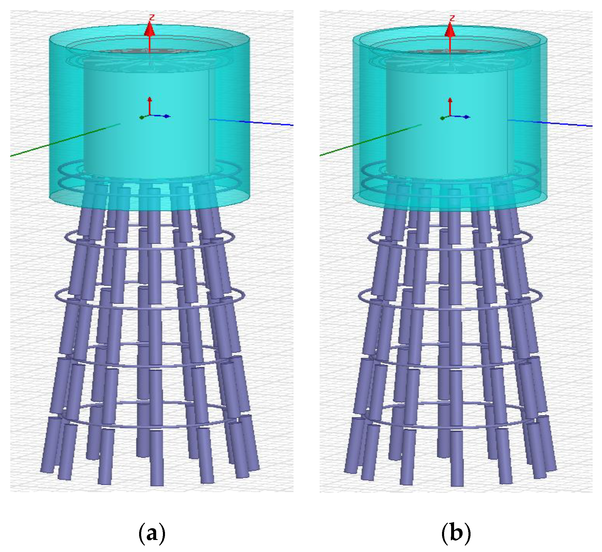
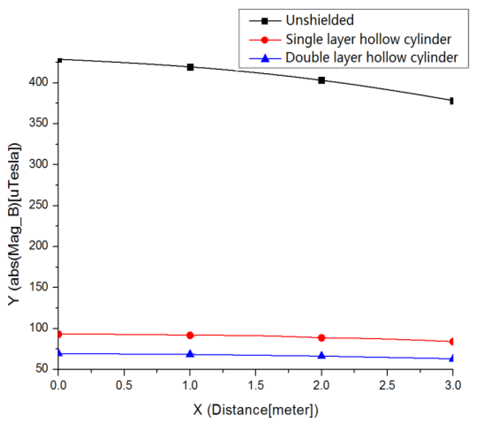
4.2. Hollow Cylindrical Shield around the Reactor

The reactor is set as shown in Figure 12, and the magnetic induction intensity distribution is obtained by simulation.
(1) As shown in Figure 12a, set a cylinder with the radius of 3 m and the height of 6 m.
(2) As shown in Figure 12b, set another cylinder outside the cylinder in Figure 12a; there should be 10 cm between the two cylinders.
It can be seen from Figure 13 that a single-layer hollow cylindrical shield, as shown in Figure 12a, is provided on the periphery of the reactor, which has a significant shielding effect, and the magnetic field of the protected area is reduced by more than 80% compared with the case where the shield is not provided. If the double-layer hollow cylindrical shield is set as shown in Figure 12b, the magnetic induction is reduced by 93% compared to when the shield is not provided. Due to the difficulty of installation and cost, the shielding scheme shown in Figure 12a can be selected.

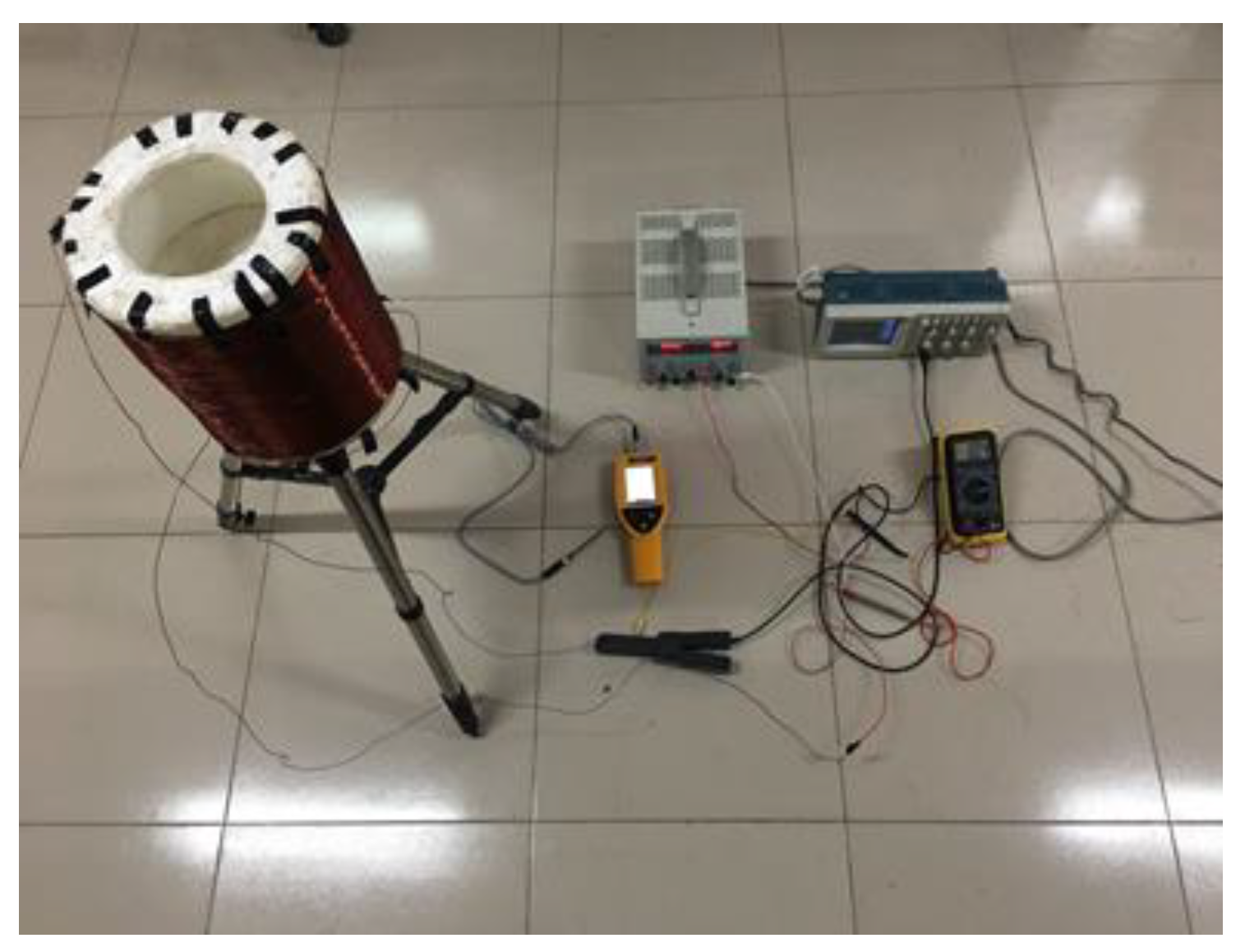
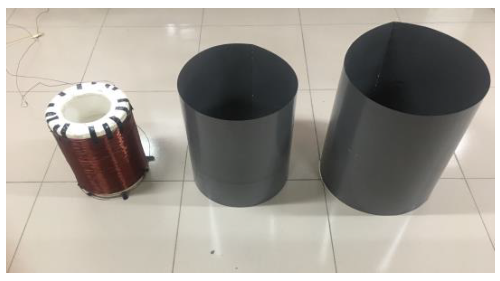
5. Small-Scale and Shielding Experiment on Magnetic Field Distribution of DC Smoothing Reactor

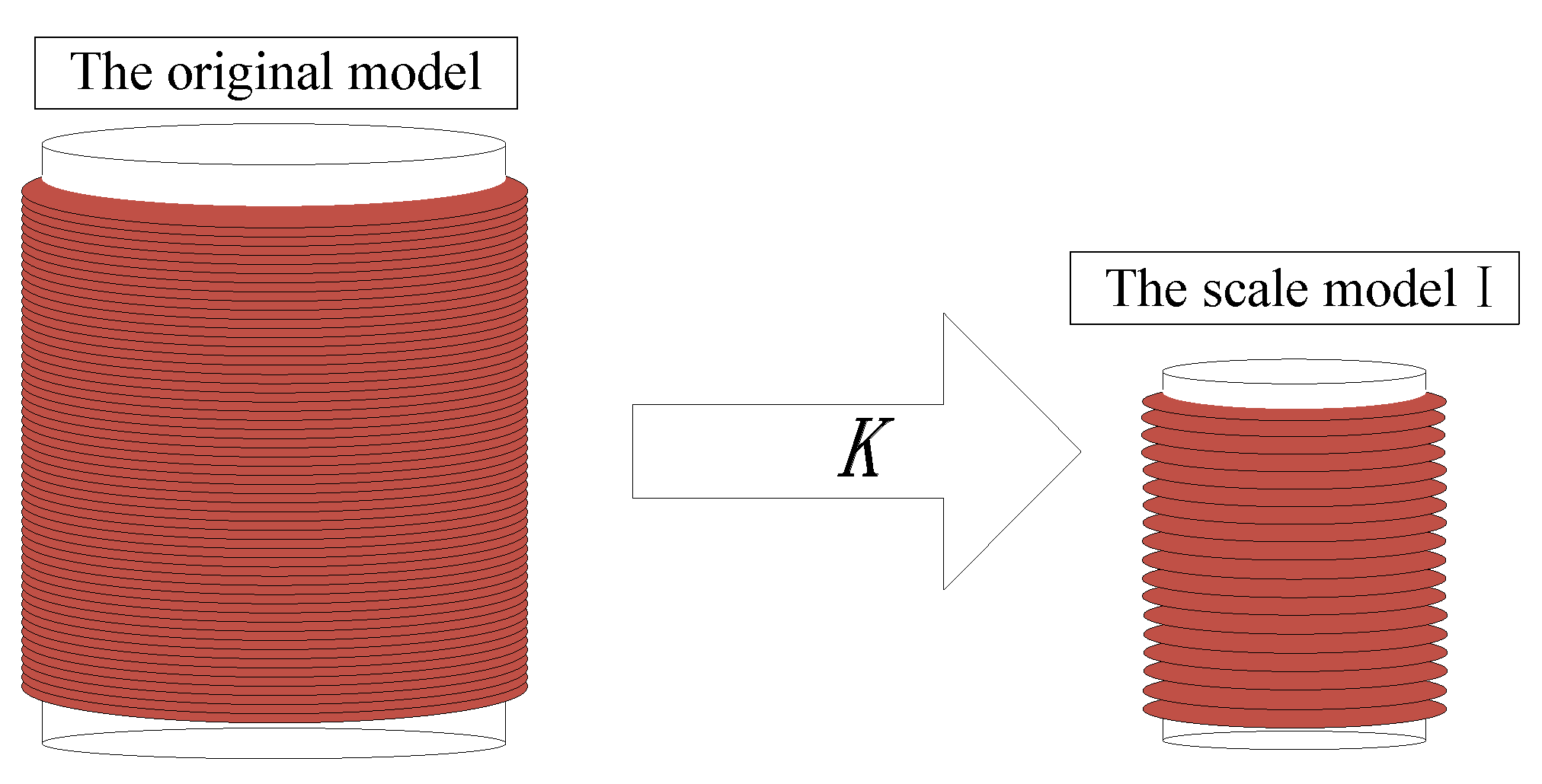
5.1. Proposal and Amendment of Scaling Rule

The DC air core reactors are mostly multi-encapsulated parallel structures in terms of heat dissipation, and every envelope is formed by parallel connection of thin windings in which a plurality of thin wires are coaxially wound. However, the magnetic field of a multi-encapsulated reactor can be completely equivalent to a simplified single-encapsulation model, and a single-encapsulation model can also be obtained by linear superposition of single-layer wires, since in the engineering process, more attention is paid to the magnetic field around the reactor rather than to the inside of it. The proximity effect and the end effect between the coils can be neglected, and the superposition principle is used to calculate the magnetic field generated by the reactor in space [29,30]. In this paper, the original model of a hollow reactor wound by a single-layer wire is established, as shown in Figure 14. The original model of the air core reactor can be reduced to the scale model I according to the scale coefficient K (0 < K < 1).
Before the scale model is established, several basic dimensions are usually determined. When the basic dimensions satisfy the similar conditions, the similarity between the original model and the scaled model is established. The scaling factor K = 1/12 is taken to determine the geometry of the scale model by the geometry of the smoothing reactor. The scaling rules for rector parameters [12] are shown in Table 4.
According to the above rule, the scale model of the air core reactor can be established and the magnetic field distribution can be measured. The scale model of the smoothing reactor shown in Table 5 was produced on the basis of the scale rules shown in Table 4.
However, the scale model is often limited by objective conditions, and the above-mentioned scale rules cannot be completely copied. Improvements must be made to make the scaled model suitable for experimental measurement and analysis. The scaling rules for rector parameters with K = 1/12 are shown in Table 6. The multi-encapsulated smoothing reactor is equivalent to a single-layer coil model, and the coil diameter is taken as:
d = D 1 + D 2 2 K
Because the number of turns is too large, considering the heat dissipation and safety of the coil, the number of turns is adjusted. The actual model parameters of the air core reactor are different from the scale rules, but the requirements can also be met by appropriate conversion. The final measurement result will not be affected by this error, provided that the current density can be met the scaling criteria. The adjustment factor is defined here as:
S = 100 2000 = 1 20 .

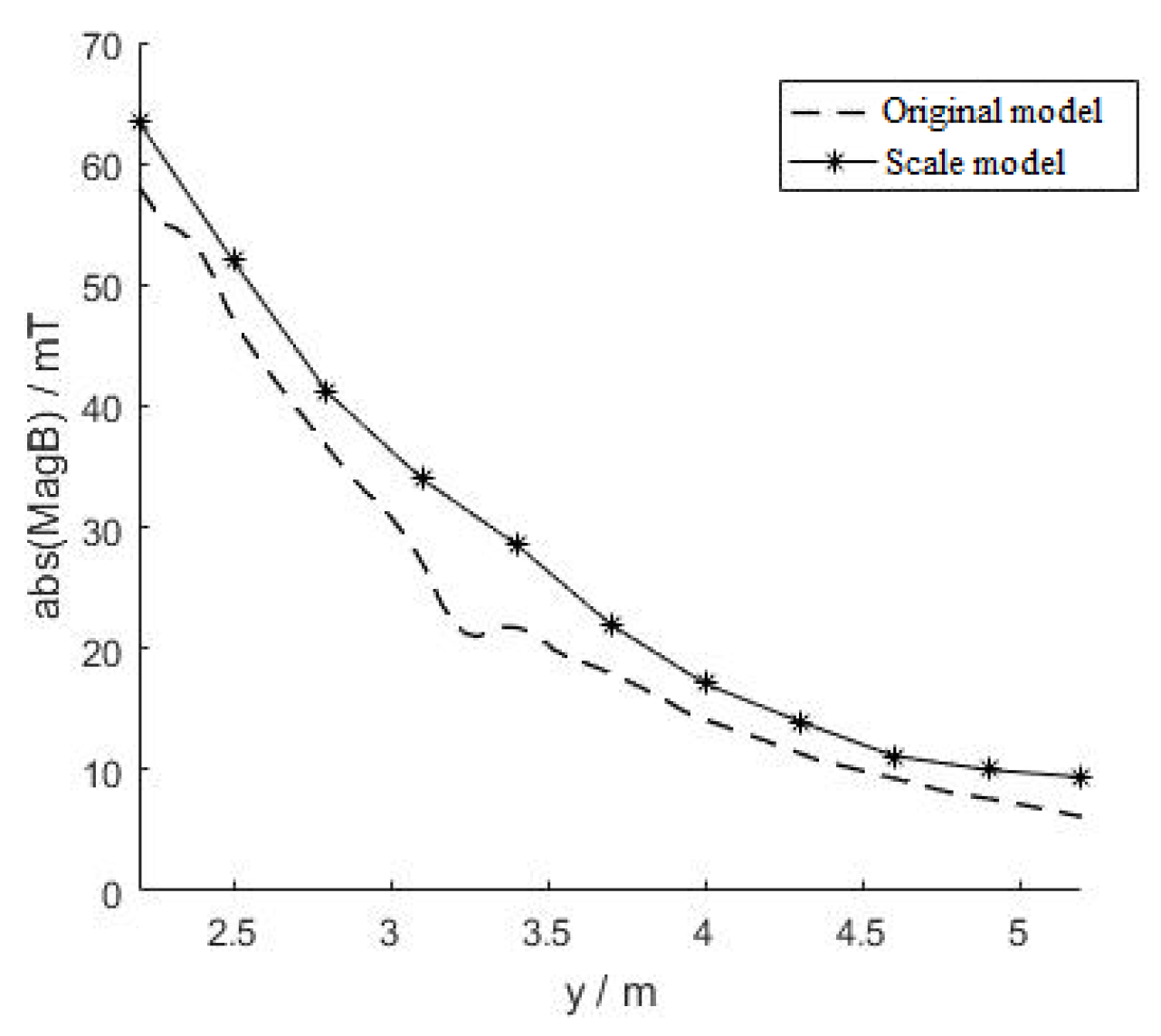
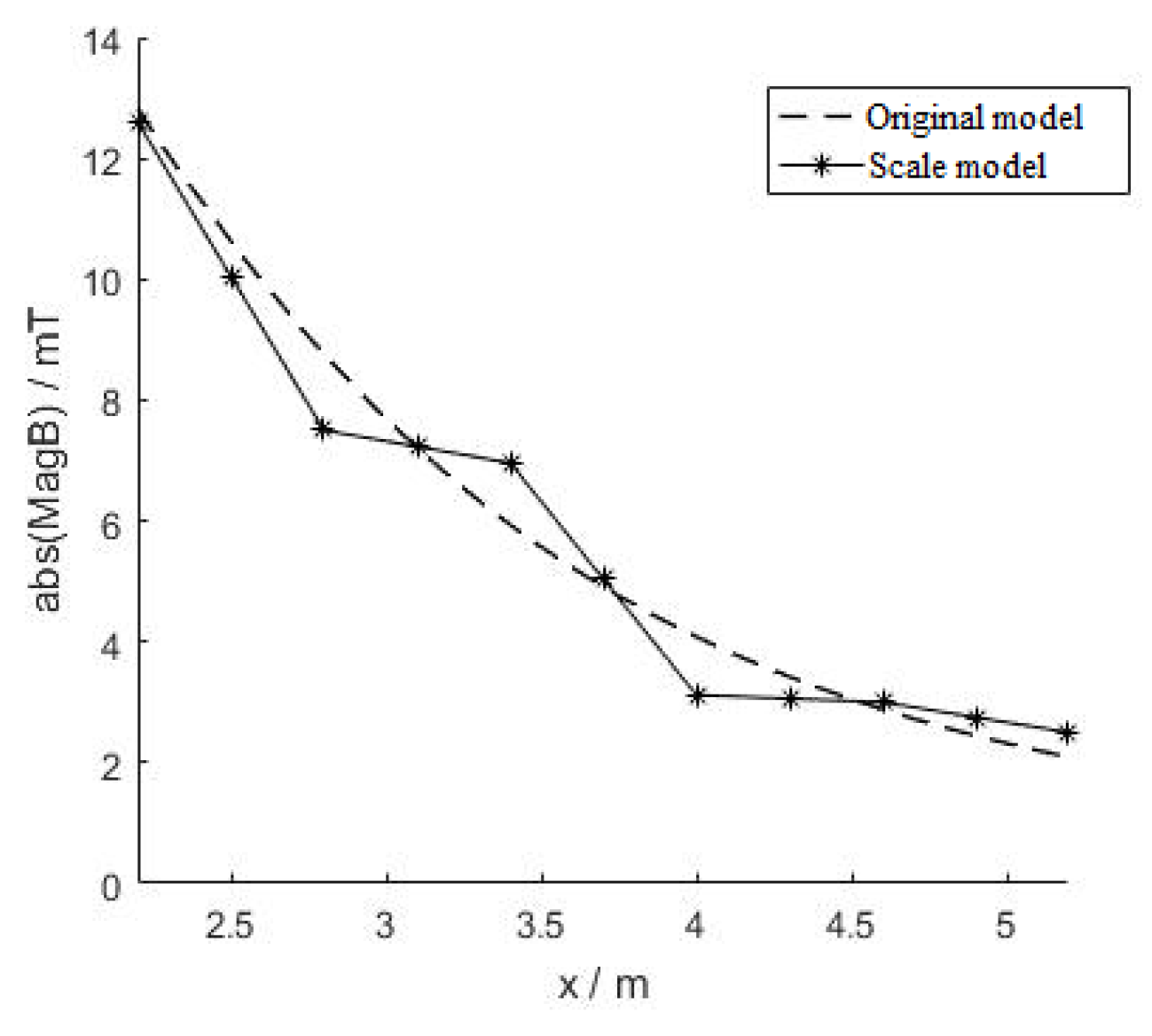
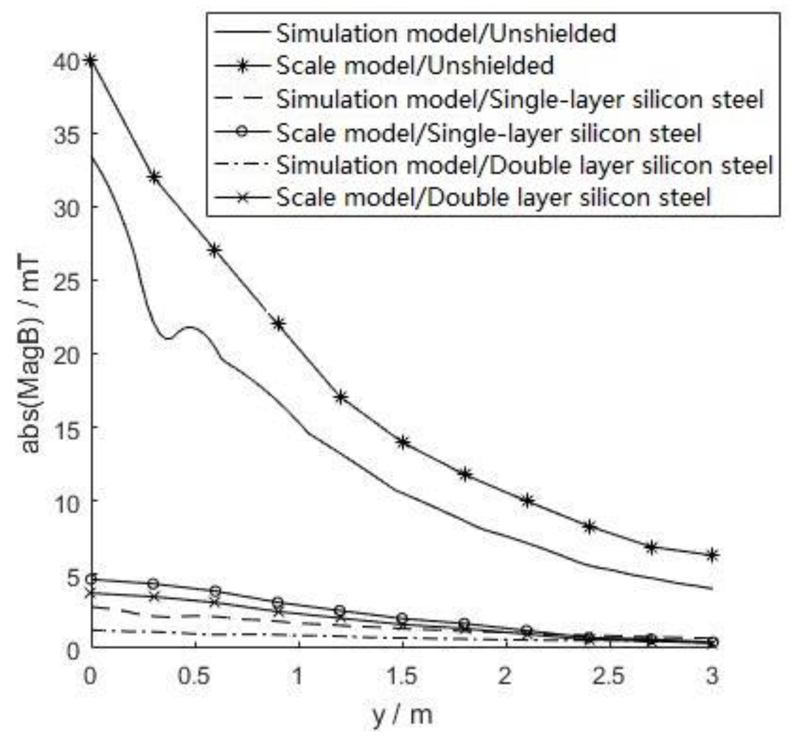
5.2. Experiment and Verification of Scale Model about Spatial Magnetic Field Distribution and Shielding

The scale model is made by the parameters shown in Table 6. The coil is connected to the DC power supply in series with the ammeter, a current probe is used to connect the oscilloscope, and the current waveform is observed, as shown in Figure 15. The wires are entangled with each other to counteract the magnetic field generated by itself, thereby reducing measurement errors.
The magnetic induction at the measurement points of the center axial, the central radial, and the bottom radial, as shown in Figure 16, were measured respectively by use of a magnetic field measuring instrument.
The magnetic induction data is processed by Section 2.3 to eliminate the influence of the geomagnetic field on the measurement results. The processed data is converted in Table 7. The comparison between the measured value of the scale model and the simulation result of the real reactor is as follows.
It can be seen from Figure 17 and Figure 18 that the measured value of the scale model is basically consistent with the simulation result of the real reactor. The magnetic field distribution of the real reactor can be reflected by the scale model, the error is small and the correctness of the scale rule is verified. The accuracy and reliability of measurement and calculation results are proved.

5.3. Research on Magnetic Field Shielding by Using Scale Mode

The shield structures of single-layer silicon steel and two-layer silicon steel are placed as shown in Figure 19, the magnetic induction in the center axial and the central radial of the coil are measured, and data is recorded.
The magnetic induction in the central axial direction of the coil is measured and converted according to scale rule, then they are compared with the magnetic field shielding simulation results of the real reactor in Figure 20. The coordinates y are the central axial distances of the measuring points from the shielding plate.
According to Figure 20, the shielding effect measured by the scale model test is basically consistent with the simulation model results. The effectiveness of the magnetic field shielding measures of the smoothing reactor proposed in this paper is further proved.

6. Conclusions

(1)
Under the full load operation condition, the magnetic induction intensity of the pole busbar reactor of the ±660 kV Jiaodong converter substation is tested, and the influence of the geomagnetic field in the measured data is analyzed.
(2)
Space magnetic field suppression measures of DC smoothing reactors are proposed, and the spatial magnetic field shielding simulation model is established and analyzed.
(3)
The magnetic field distribution scale rule of DC smoothing reactors is proposed, and an experimental platform is established to verify the feasibility of the space magnetic field suppression measures.

Author Contributions

Conceptualization, L.Z. and Y.S.; Methodology, J.Y., W.Z. and Y.W.; Software, J.Y., W.Z. and L.Z.; Validation, J.Y., W.Z. and Y.S.; Formal Analysis, W.Z.; Investigation, Y.W. and L.Z.; Resources, L.Z., Y.S. and Y.F.; Data Curation, J.Y., L.Z. and Y.S.; Writing—Original Draft Preparation, J.Y., W.Z. and Y.W.; Writing—Review & Editing, J.Y.; Visualization, J.Y. and W.Z.; Supervision, Y.S. and Y.F.; Project Administration, L.Z., Y.S. and Y.F.; Funding Acquisition, Y.S.

Funding

This article is supported by the State Grid Corporation Headquarters Science and Technology Project Funding (SGSG0000JSJS1700014).

Conflicts of Interest

The authors declare no conflict of interest.

References

  1. Morozionkov, J.; Virbalis, J.A. Magnetic field of power plant air core reactor. Electron. Electr. Eng. 2007, 7, 67–70. [Google Scholar]
  2. The Trench Group. Dry-Type Air-Core Shunt Reactor Specification; E 630.21; Trench: Toronto, ON, Canada, 2006. [Google Scholar]
  3. GB/T 25092-2010. Dry-Type Air-Core Smoothing Reactors for HVDC Applications; Standardization Administration of China: Beijing, China, 2010.
  4. Chen, T. Research on Operation State of UHVDC Smoothing Reactor; China Water & Power Press: Beijing, China, 2016. [Google Scholar]
  5. Hardell, L.; Sage, C. Biological Effects from electromagnetic field exposure and public exposure standards. Biomed. Pharmacother. 2008, 62, 104–109. [Google Scholar] [CrossRef] [PubMed]
  6. Li, N.; Wu, X.; Lu, Y. Analysis of exposure limits standards of power frequency electric and magnetic fields for general public and actual situation. In Proceedings of the CIGRE, Xi’an, China, 25–28 September 2011. [Google Scholar]
  7. Salinas, E.; Liu, Y.Q.; Souza, P.; Atalaya, J.; Cruz, P.; Daalder, J. Design and validation of power-frequency magnetic field conductive shielding for underground cables. In Proceedings of the CIRED’2005—18th International Conference and on Electricity Distribution, Turin, Italy, 6–9 June 2005; pp. 1–4. [Google Scholar]
  8. Wang, Q.; Li, W.; Wang, B. R & D of dry type smoothing reactor for ±800kV HVDC power transmission. Electr. Equip. 2006, 7, 11–14. [Google Scholar]
  9. Salinas, E.; Atalaya, J.; Hamnerius, Y.; Solano, C.J.; Gonzales, D.; Contreras, C.; Leon, C.; Sumari, M.A.; Dimitriou, S.; Rezinkina, M. A new technique for reducing extremely low frequency magnetic field emissions affecting large building structures. Environmentalist 2007, 27, 571–576. [Google Scholar] [CrossRef]
  10. Xiao, C. Design and Calculation Analysis of ±800kV/6250A UHVDC Dry-type Smoothing Reactor. Ph.D. Thesis, North China Electric Power University, Beijing, China, 2017. [Google Scholar]
  11. Enohnyaket, M.; Ekman, J. Analysis of air-core reactors from DC to very high frequencies using PEEC models. IEEE Trans. Power Deliv. 2009, 24, 719–729. [Google Scholar] [CrossRef]
  12. Zou, L.; Gong, P.; Zhang, L. Small-scale Experiment and Model Simplification of Space Magnetic Fields Around Air-core Reactors. High Volt. Eng. 2014, 40, 1675–1682. [Google Scholar]
  13. Wang, Q.; Zhang, Y.; Li, Y. The power frequency magnetic field distribution around dry-type air-core reactor. Trans. China Electrotech. Soc. 2009, 24, 8–13. [Google Scholar]
  14. Du, H.; Wen, X.; Lu, H.; Jiang, Z. Magnetic field distribution around 35 kV three-phase air-core reactors. High Volt. Eng. 2012, 38, 2858–2862. [Google Scholar]
  15. Yu, Q.; Sebo, S.A. Simplified magnetic field modeling and calculation of large air-core reactor coils. IEEE Trans. Magn. 1996, 32, 4281–4283. [Google Scholar] [CrossRef]
  16. Yu, Q.; Sebo, S.A. Calculation accuracy of the planar filament current loop stack model of large air-core reactor coils. IEEE Trans. Magn. 1997, 33, 3313–3315. [Google Scholar] [CrossRef]
  17. Ji, J.; Yu, J.H.; Yuan, Y.F.; Yang, G.; He, J. Research of the magnetic field distribution and protection body setting for air-core reactor. High Volt. Appar. 2009, 45, 61–64, 68. [Google Scholar]
  18. Wang, J.M.; Jing, C.Y.; Wu, W.G.; Sun, Y.L.; Wang, Y.H.; Cheng, Z.G. Numerical analysis of current distribution and leakage magnetic field characteristics of EHV dry-type smoothing reactor. Transformer 2010, 47, 20–23. [Google Scholar]
  19. Cheng, X.; Lv, J.; Gou, R.; Zhao, J. Study for Arrangement of the Smoothing Reactor in ±800 kV UHVDC Project. In Proceedings of the 2008 International Conference on High Voltage Engineering and Application, Chongqing, China, 9–12 November 2008. [Google Scholar]
  20. Chen, T.; Cao, J.; Zhou, G.; Jiang, Z.; Wang, Y.; Wen, X. Electric field research of ±800 kV dry-type smoothing reactor. In Proceedings of the 2014 17th International Conference on Electrical Machines and Systems (ICEMS), Hangzhou, China, 22–25 October 2014. [Google Scholar]
  21. GB 8702-2014. Controlling Limits for Electromagnetic Environment; Ministry of Ecology and Environment: Beijing, China, 2015.
  22. Official Journal of the European Union. Directive 2004/40EC of the European Parliament and of the Council of 29 April 2004 on the minimum health and safety requirements regarding the exposure of workers to the risks arising from physical agents (electromagnetic fields) (18th individual Directive within the meaning of Article 16(1) of Directive 89/391/EEC).2004, L 159/1-26. Off. J. Eur. Union 2004, 159, 1–26. [Google Scholar]
  23. ICNIRP. Guidelines for limiting exposure to time-varying electric and magnetic fields (1 Hz–100 kHz). Health Phys. 2010, 99, 818–836. [Google Scholar]
  24. Kheifets, L.; Ahlbom, A.; Crespi, C.M.; Draper, G.; Hagihara, J.; Lowenthal, R.M.; Mezei, G.; Oksuzyan, S.; Schüz, J.; Swanson, J.; et al. Pooled analysis of recent studies on magnetic fields and childhood leukemia. Br. J. Cancer 2010, 103, 1128–1135. [Google Scholar] [CrossRef] [PubMed]
  25. Bakker, J.F.; Paulides, M.M.; Neufeld, E.; Christ, A.; Chen, X.L.; Kuster, N.; Van Rhoon, G.C. Children and adults exposed to low-frequency magnetic fields at the ICNIRP reference levels: Theoretical assessment of the induced electric fields. Phys. Med. Biol. 2012, 57, 1815–1829. [Google Scholar] [CrossRef] [PubMed]
  26. DL/T 354-2010. Guide for Maintenance of Converter Transformer and Smoothing Reactor; National Energy Administration: Beijing, China, 2011.
  27. International Commission on Non-ionizing Radiation Protection. Guidelines on limits of exposure to static magnetic fields. Health Phys. 2009, 96, 504–514. [Google Scholar] [CrossRef] [PubMed]
  28. Zeng, M.; Jiao, X.; Xiao, N. Simulation and Research of Air-core Reactor Magnetism-Screened Effects Based on Ansoft Maxwell. High Power Convert. Technol. 2013, 2, 2. [Google Scholar]
  29. Du, S.W.; Song, C.Y.; Zhu, C.J.; Chen, G.Q.; Fu, Z.C. Simplified calculation and coverage of power frequency magnetic field around 10 kV air-core reactors. High Volt. Appar. 2006, 42, 179–182. [Google Scholar]
  30. Sharp, M.R.; Andrei, R.G.; Werner, J.C. A novel air-core reactor design to limit the loading of a high voltage interconnection transformer bank. In Proceedings of the IEEE Power Engineering Society Summer Meeting, Chicago, IL, USA, 21–25 July 2002. [Google Scholar]
Figure 1. Pole bus smoothing reactor of the Jiaodong ±660 kV converter substation.
Energies 12 00937 g001
Figure 2. Layout diagram of smoothing reactors.
Energies 12 00937 g002
Figure 3. Magnetic field distribution of pole I smoothing reactor.
Energies 12 00937 g003
Figure 4. Influence analysis of the geomagnetic field.
Energies 12 00937 g004
Figure 5. Measured value and processed value of pole I reactor.
Energies 12 00937 g005
Figure 6. Reactor simulation model.
Energies 12 00937 g006
Figure 7. Magnetic field distribution simulation results.
Energies 12 00937 g007
Figure 8. Comparison of simulation result and processed data.
Energies 12 00937 g008
Figure 9. Shield installation diagram below the reactor.
Energies 12 00937 g009
Figure 10. Shielding effect of different materials.
Energies 12 00937 g010
Figure 11. Shielding effect of different heights.
Energies 12 00937 g011
Figure 12. Shield at different positions. (a) single-layer hollow cylindrical shield; (b) double-layer hollow cylindrical shield.
Energies 12 00937 g012
Figure 13. Shielding effect of different positions.
Energies 12 00937 g013
Figure 14. Original model and small-scale model I.
Energies 12 00937 g014
Figure 15. Experimental connection.
Energies 12 00937 g015
Figure 16. Distribution of measuring points.
Energies 12 00937 g016
Figure 17. Central axial magnetic field of scaled model and actual reactor.
Energies 12 00937 g017
Figure 18. Center radial magnetic field of scaled model and actual reactor.
Energies 12 00937 g018
Figure 19. Position of shield.
Energies 12 00937 g019
Figure 20. Central axial magnetic induction distribution with shielding.
Energies 12 00937 g020
Table 1. Measured data of magnetic field distribution B (μT).
y/m 02468101214
x/m
−20132131124123118111109103
−14190188181178166141131124
−10266264247232213186164146
−8306300285263235207182159
−6353347323299253217191169
−4---306271235191169
−2---317277238211180
0---323267236204174
2---298266230192170
4---284250206181159
6301295277246211184161142
8249241224202179162153129
10197190179164150136125118
14119117114112107989694
203638465361637075
Table 2. Measured value and processed value.
x/mMeasured Value/μTx/mMeasured Value/μTProcessed Value/μT
2053−2012373.27
14112−14178136.07
10164−10232191.73
8202−8263226.69
6246−6299267.13
4284−4306289.04
2298−2317301.74
0323--317.38
Table 3. Parameters of shielding plate.
Materialμrσ × 107/(S·m−1)r1/md1/mmh/m
Silicon steel100001.02.351
101
351
Iron40001.032.351
Aluminum1.0000213.82.351
Table 4. Theoretical scaling rules of air reactor parameters.
TypeOriginal ModelScale ModelTypeOriginal ModelScale Model
Wire lengthlKlVoltageUKU
Wire widthWKWCurrentIK2I
Cross-sectional areaAK2AResistanceRK−1R
Axial heightHKHInductanceLKL
Bottom radiusrKrMagnetic inductionBKB
Table 5. Parameters of air reactor.
TypeParametersTypeParameters
Rated voltage±800 kVRated current4000 A
Rated inductance75 mHEnvelope layer20
Coil height (H)4200 mmThe inner diameter of encapsulation (D1)1882 mm
The outer diameter of encapsulation (D2)4228 mmEncapsulation current200 A
Number of turns100Total number of turns2000
Table 6. Parameters of small-scale model.
ParametersValueAdjustment Value
Coil diameter (d)250 mm-
Coil height (h)350 mm-
Number of turns2000100
Current1.38 A-
Table 7. Correction value and conversion value.
NameCorrection ValueConversion Value
Magnetic inductionB 1 K × S × B
Axis sizeXK−1X

