Article

Key Parameters of Roof Cutting of Gob-Side Entry Retaining in a Deep Inclined Thick Coal Seam with Hard Roof

1
State Key Laboratory for Geomechanics & Deep Underground Engineering, China University of Mining & Technology, Beijing 100083, China
2
School of Mechanics and Civil Engineering, China University of Mining & Technology, Beijing 100083, China
*
Authors to whom correspondence should be addressed.
Energies 2019, 12(5), 934; https://doi.org/10.3390/en12050934
Submission received: 11 January 2019 / Revised: 16 February 2019 / Accepted: 10 March 2019 / Published: 11 March 2019

Abstract

:
Gob-side entry retaining by roof cutting (GERRC) employed in a deep inclined thick coal seam (DITCS) can not only increase economic benefits and coal recovery, but also optimize surrounding rock structure. In accordance with the principles of GERRC, the technology of GERRC in DITCS is introduced and a roof-cutting mechanical model of GERRC is proposed to determine the key parameters of the depth and angle of RC. The results show that the greater the RC angle, the easier the caving of the goaf roof, but the length of cantilever beam increases. The depth of RC should account for the dip angle of the coal seam when the angle is above 20°. Increasing the coal seam dip angle could reduce the volume of rock falling of the goaf roof, but increase the filling height of the upper gangue to slide down. According to numerical model analysis of the stress and displacement of surrounding rock at different depths and angles of RC, when the depth of RC increased from 9 m to 13 m, the distance between the stress concentration zone and the coal side is increased. When the angle of RC increased from 0° to 20°, the value of roof separation is decreased. GERRC was applied in a DITCS with 11 m depth and 20° RC angle, and the field-measured data verified the conclusions of the numerical model.

1. Introduction

At present, most coal mines use retaining coal pillars to maintain the roadway. The loss of coal pillars generally accounts for about 40% of the total coal loss of the whole mine [1]. Backward coal mining technology and methods not only reduce the rate of coal resource mining, with serious resource waste, but also pose a huge threat to coal mine production. During mining of the working face, stress concentration is formed in the upper part of the coal pillar, causing large deformation and roof collapse of the entry, as well as geological disasters such as coal burst, and coal and gas outburst [2,3,4,5]. However, gob-side entry retaining (GER) technology can not only improve the recovery rate of coal mining, but also avoid major geological disasters. It is one of the sustainable development directions of coal mines.
Some major coal-producing countries in the world use reciprocating methods in order to increase the recovery rate of coal resources, increase the continuity of production, and improve the economic benefits of mines. The study of GER technology has been ongoing for a long time [6,7,8,9,10,11]. In 2008, He [12,13] proposed the theory of cutting short arm beam, that is, presplit cracking along the roof of the roadway. The roof structure is changed actively and the stress state of the roadway surrounding rock is optimized, which is conducive to the stability of roadway surrounding rock and provides a theoretical basis for the technology of gob-side entry retaining by roof cutting (GERRC). The innovative GERRC method was first successfully applied at the site of the 2442 working face of Baijiao Coal Mine of Sichuan Coal Group in 2010.
With the expansion of GERRC application, its application conditions are also expanding. From thin to thick coal seams [14,15,16,17,18], from shallow to deep [19,20,21], and from composite to hard roofs [22,23,24], GERRC is widely used for continuous technological progress and theoretical innovation.
In this paper, the GERRC technique was used under conditions of a deep inclined thick coal seam with a hard roof. The GERRC method and technology are summarized and a short cantilever beam mechanical model is proposed to determine the key parameters GERRC, including cutting depth and angle. Based on mechanical and numerical models, the depth and angle of roof cutting were determined. A field case study in the Fucheng coal mine, Inner Mongolia Province, China, is also presented to validate the model results.

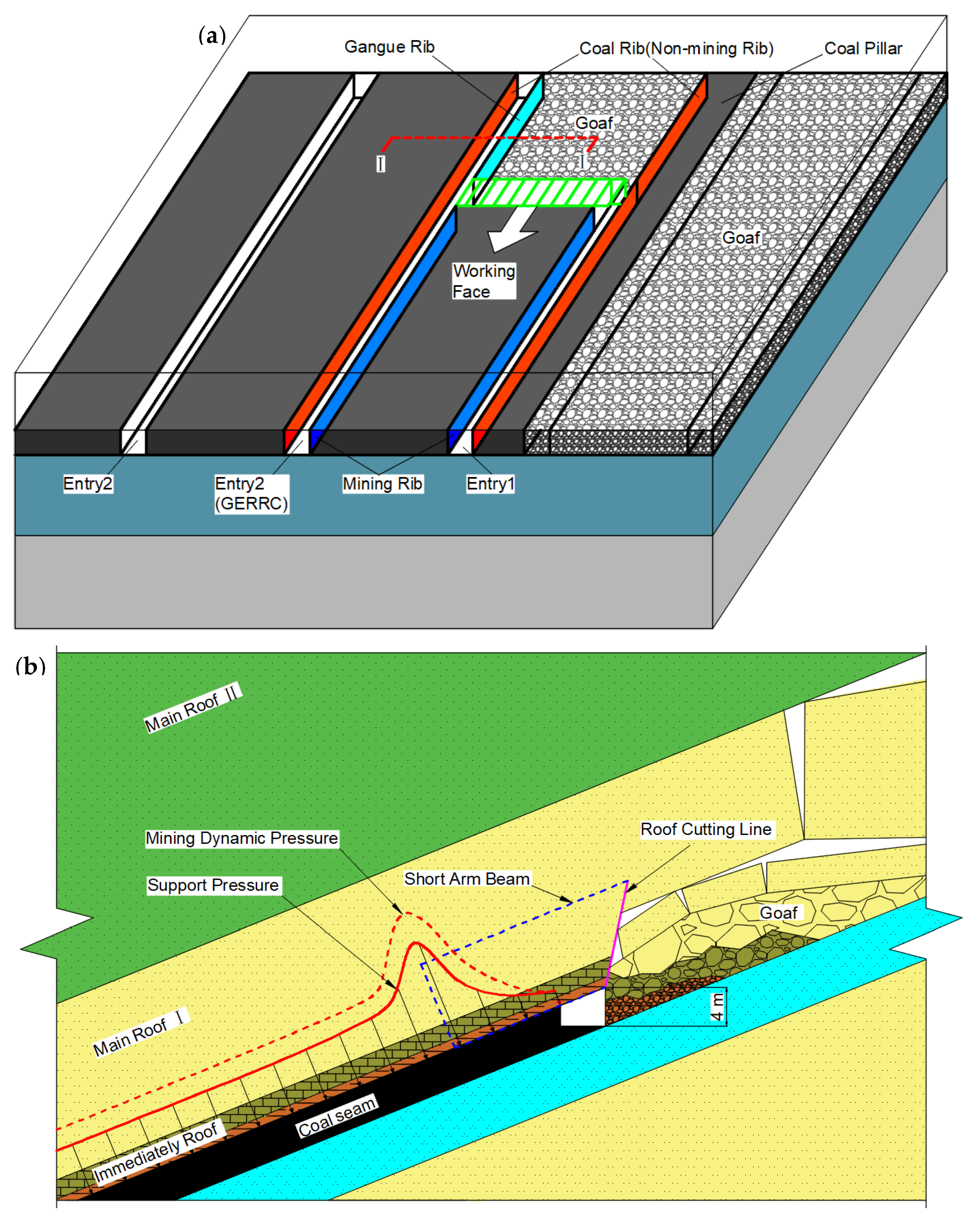
2. Method and Technology of GERRC

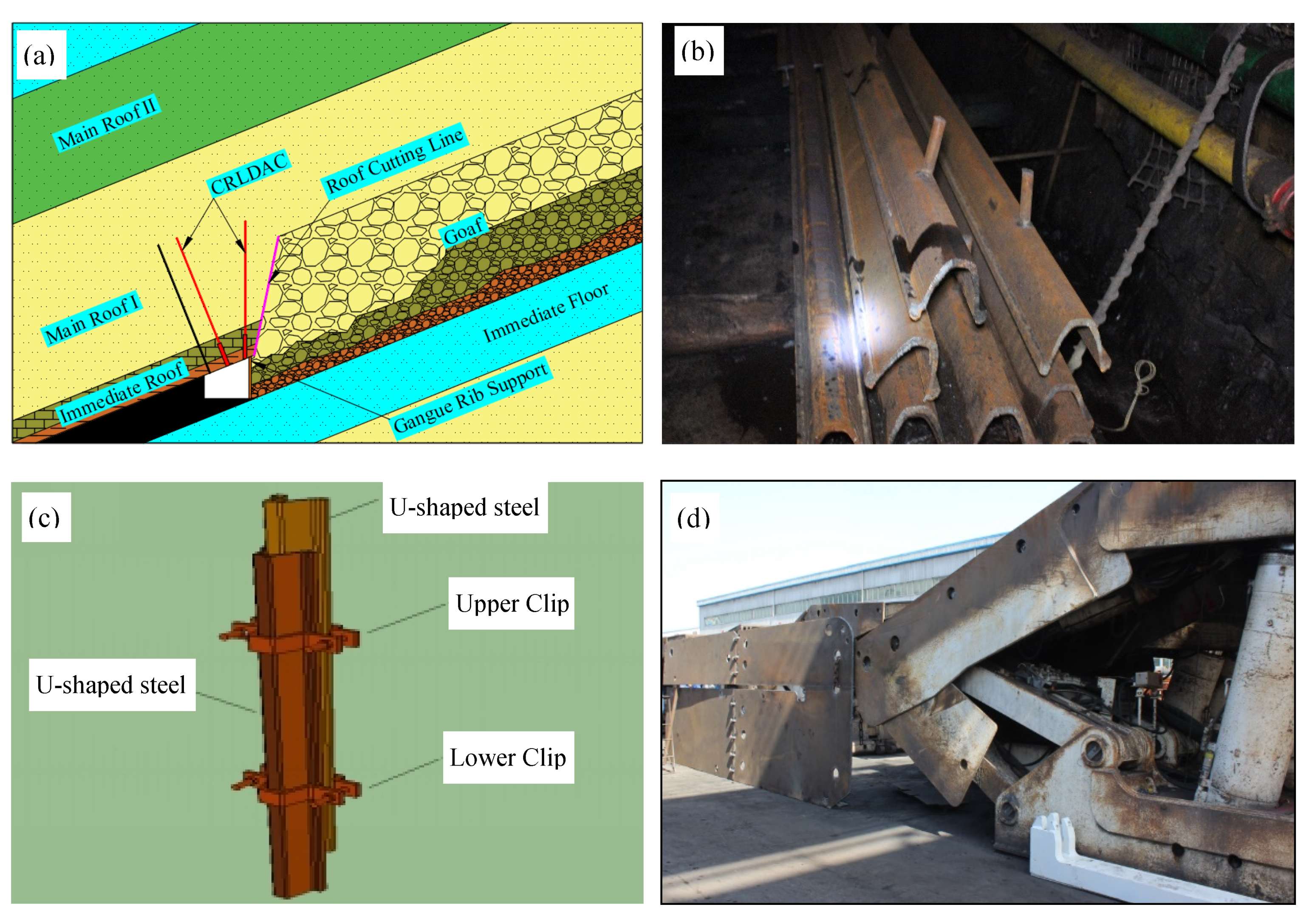
2.1. Principles of GERRC

In the front of the working face, directional presplit blasting was carried out in the roof of the mining rib along with mining direction. The roofs connection between the entry and the goaf was actively cut off, forming a short arm beam structure. A constant resistance large deformation anchor cable was used to hang the short arm beam under the stratum rock to ensure the stability of the roof of entry. The rock of the goaf roof caved along the directional presplit face after mining and generated the gangue rib of entry (GERRC), with the gangue rib used for support to ensure that the gangue did not flow into the entry. GERRC technology utilizes the mining-out area, mining pressure, the rock mass of the goaf roof, and the rock’s fragment-expanding characteristics to make the mining-out area full after mining, and utilizes the original entry as the next working face entry because the immediate roof of entry forms a short arm beam. The stress distribution of surrounding rock of the entry is optimized, reducing the entry immediate roof gravity, and the load of the main roof is beneficial for entry retaining. Compared with the traditional filling and wall-retaining GER, the operation is simple, the cost is low, and the entry retaining effect is better. At the same time, since there is no need to build a wall at the side of the entry (GER) to ensure the stability of the roof, the mining-out rib of the retaining entry will not have stress concentration, which can avoid or reduce the occurrence of rib spalling and roof falling, coal burst, and coal and gas outburst when the next working face is being mined. Therefore, in order to ensure the stability of the short arm beam (Figure 1) and the good effect of entry retaining in a deep inclined thick coal seam with hard roof, technical measures and methods suitable for this condition are required.

2.2. GERRC Techniques in a Deep Inclined Thick Coal Seam (DITCS) with Hard Roof (HR)

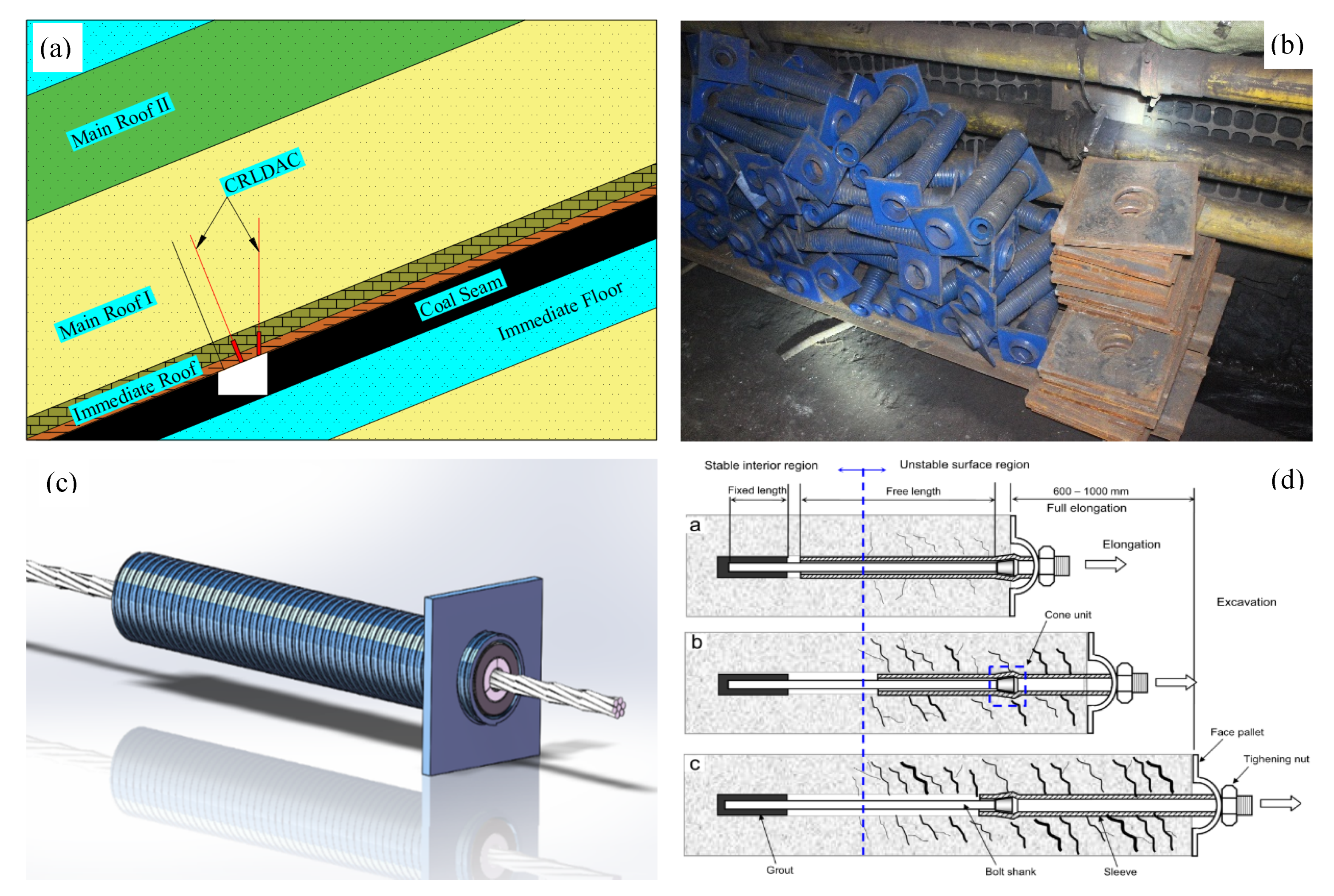
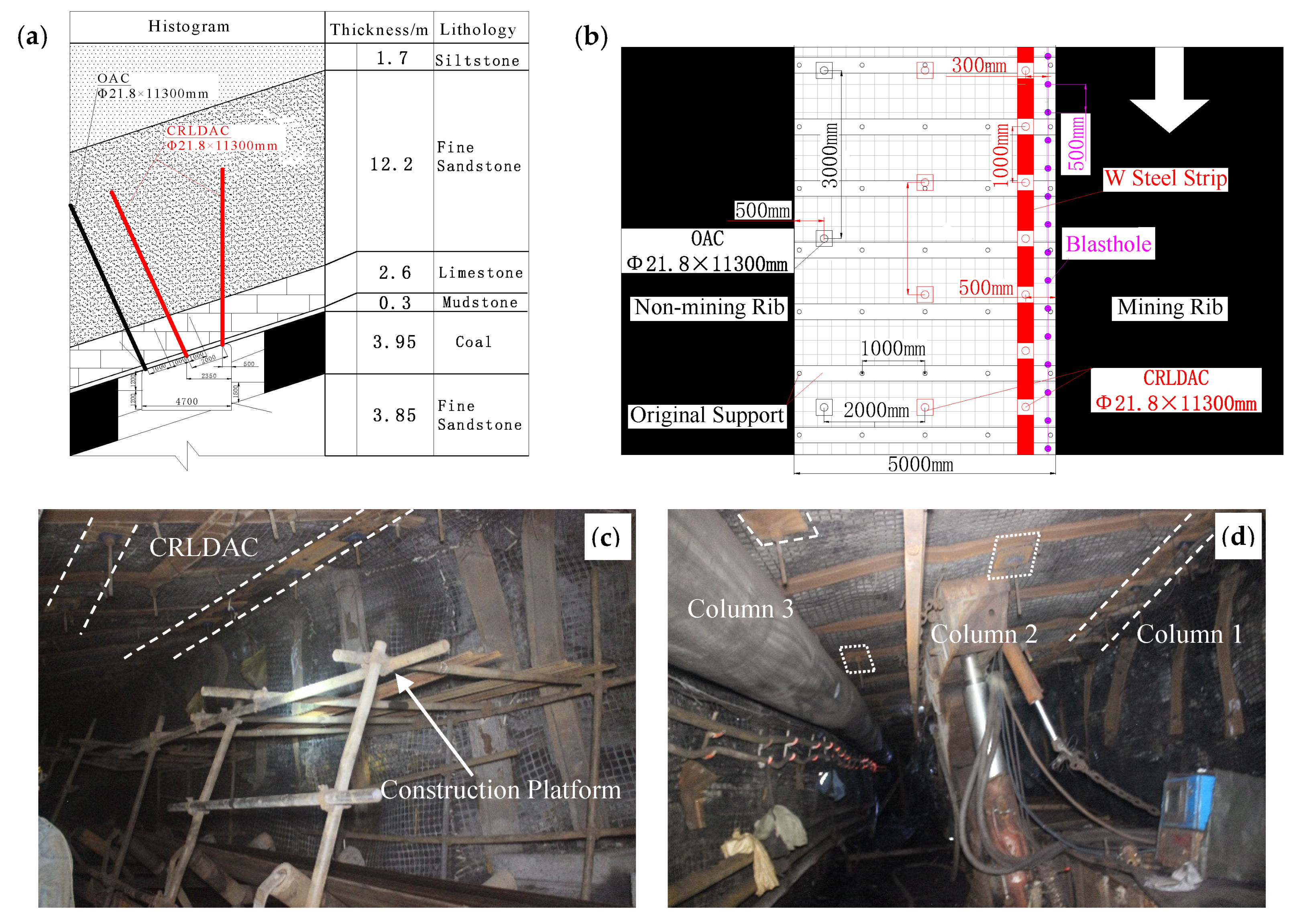
2.2.1. Constant Resistance Large Deformation Anchor Cable (CRLDAC)

First, before mining the working face, a constant-resistance large-deformation anchor cable was installed to reinforce the strength of the entry roof (Figure 2a). He [25,26] developed a constant resistance large deformation anchor cable support material in 2009. The new constant resistance anchor cable can reach a constant support resistance of 350 KN, and the amount of deformation can be up to 1000 mm. The constant resistance large deformation anchor cable is composed of a constant resistance device, a cable body, and a tray (Figure 2b,c). Adjacent constant resistance large deformation anchor cables are connected to each other by a W steel strip to form an integral structure.
The working principle of the CRLDAC can be divided into three stages: In the initial stage, since the influence of mining pressure is weak, the tension of the CRLDAC slowly increases from the pretightening force of 250 KN. In the deformation stage, the influence of mining pressure is intense. When the tension of the CRLDAC rises quickly and exceeds 350 KN, the constant resistance device moves synchronously with the surrounding rock and produces large axial deformation. It also produces radial plastic deformation to absorb energy. In the stable stage, the influence of mining pressure ends. Deformation of the CRLDAC gradually stops and its tension decreases (Figure 2d).

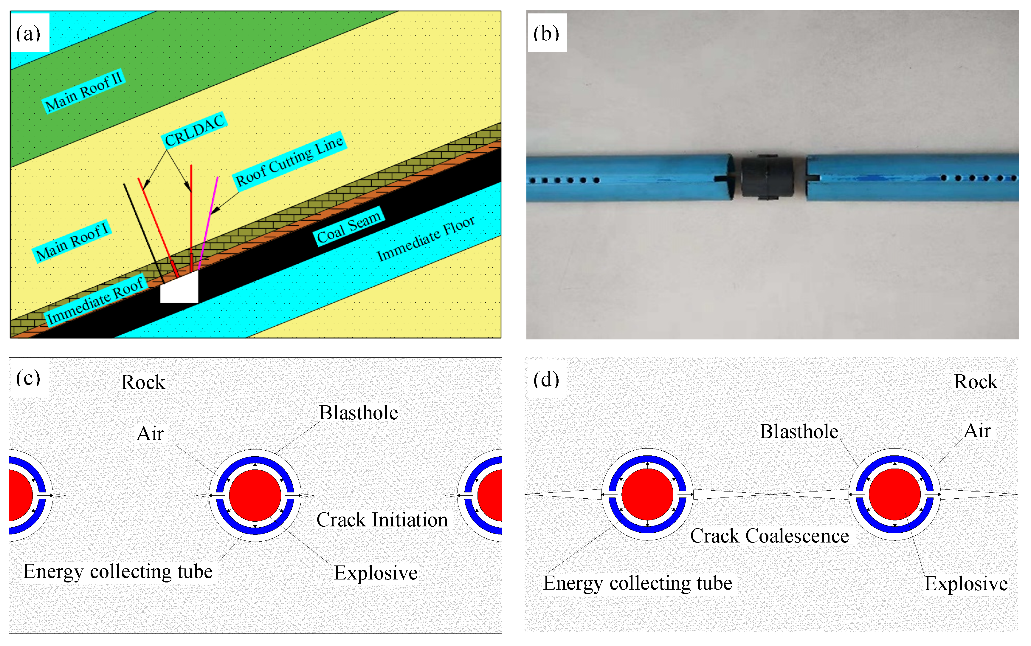
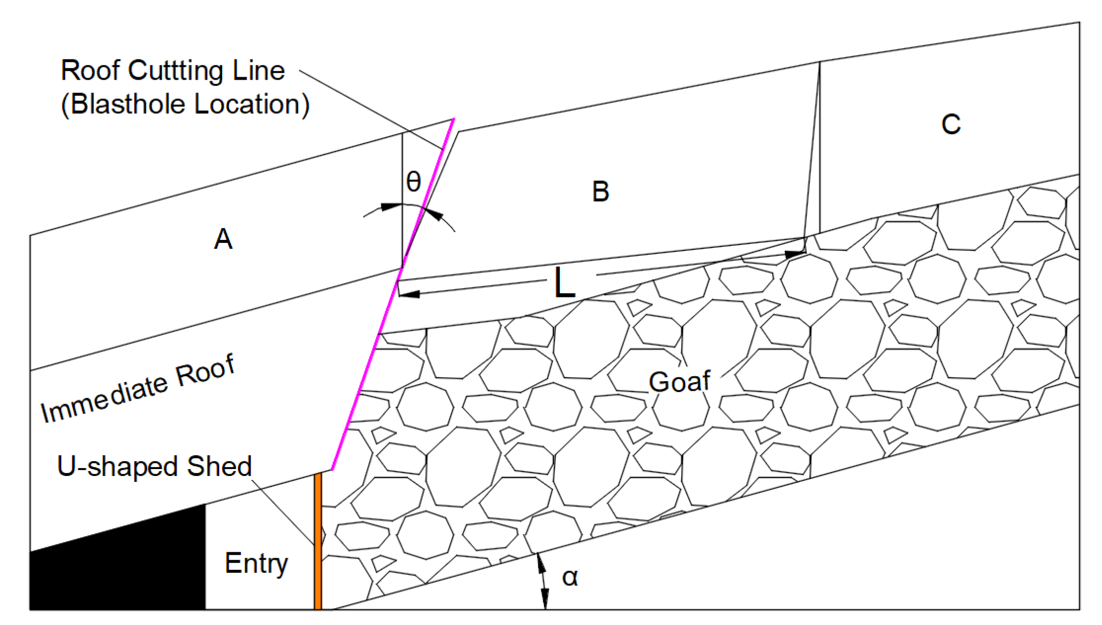
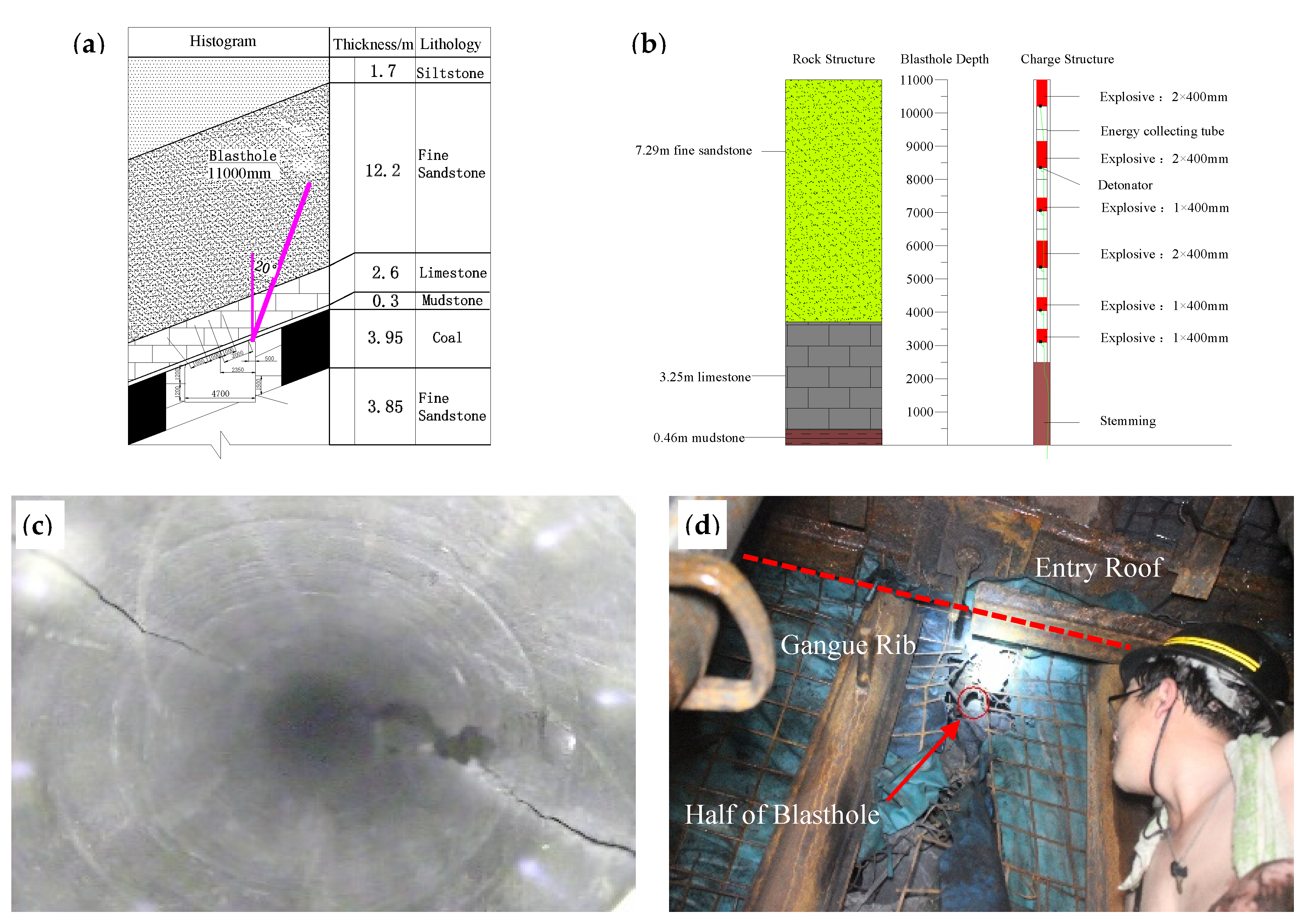
2.2.2. Directional Presplit Blasting

Second, after reinforcing the entry roof strength, directional presplit blasting is applied to the entry roof (Figure 3a). The technology utilizes a newly developed point-line energy collecting tube to realize directional control blasting [27,28,29] (Figure 3b), placing the explosive into the device with a concentrating effect in two set directions. After the explosive is detonated, the surrounding rock of the blasthole is subjected to compressive stress in a nonset direction, and the tensile stress works on the set direction, so that the rock body forms a precracking surface according to the set direction.
The construction process is simple. In the application, it only needs to construct the blasthole on the precracking line of the entry roof, put the energy collecting tube filled with explosive into the blasthole, and ensure that the direction of concentrated energy is consistent with the precracking direction of the rock mass. The detonation product will form a concentrated energy flow in two set directions and generate a concentrated tensile stress in the blasthole wall so that the precracking blasthole penetrates in the direction of concentrated energy to form a precracking surface. Since only the rock in the direction of concentrated energy is broken, the unit consumption of explosives will be greatly reduced. At the same time, due to the protection of the surrounding rock by the energy collecting tube, the damage of the rock mass around the blasthole is greatly reduced, so the technology can achieve the precracking surface and protect the entry roof (Figure 3c,d).

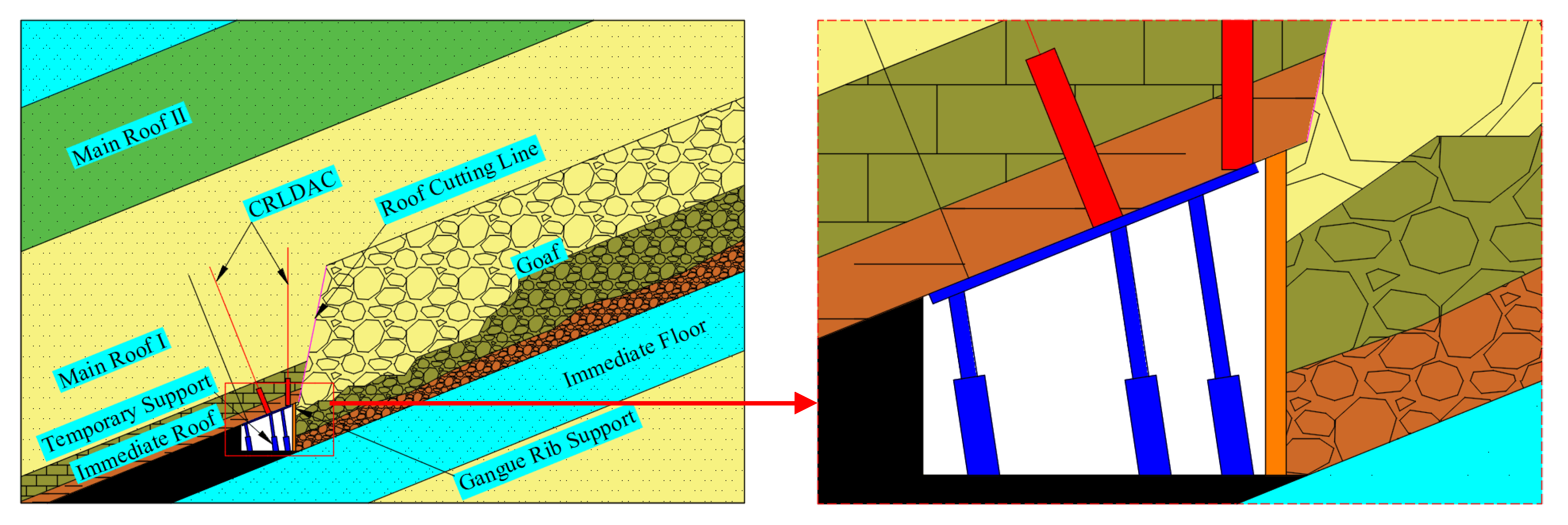
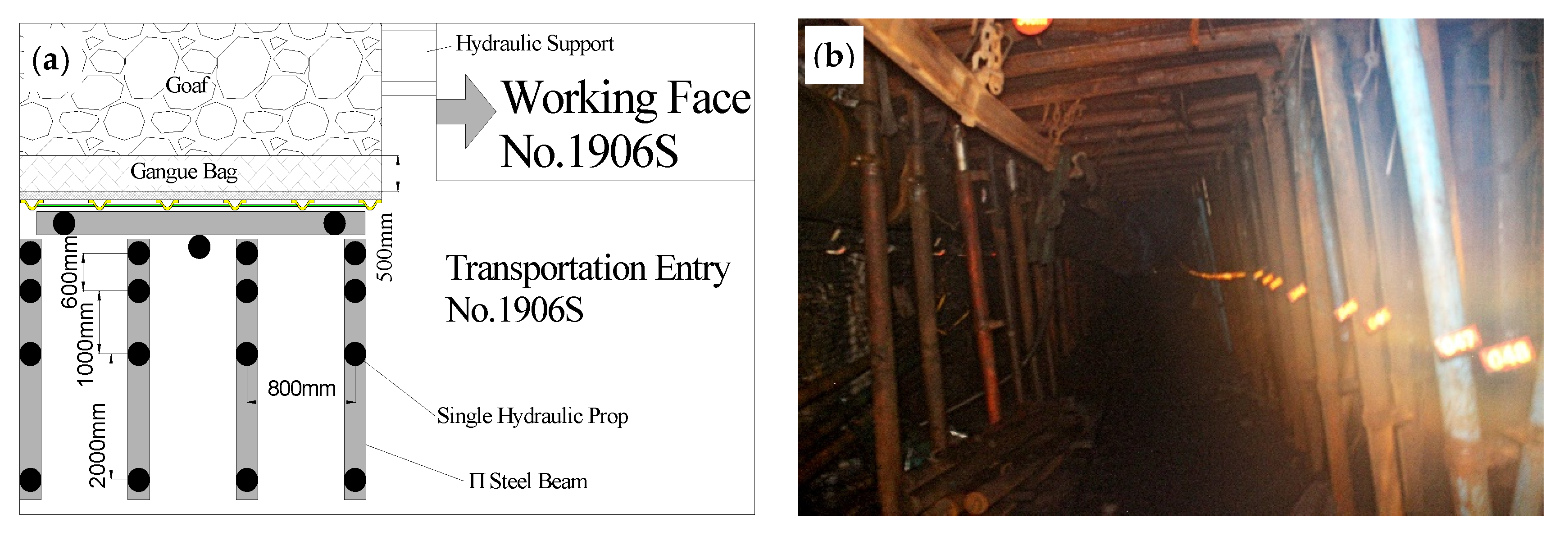
2.2.3. Temporary Support in the Entry

Third, after mining the working face, the temporary support in the entry ensures the stability of the entry roof under the influence of dynamic pressure (Figure 4). Deformation of the gob-side entry roof can be divided into three stages according to time: development deformation stage, mining deformation stage, and second mining deformation stage. With the mining of the working face and the movement of the bracket, the roof of the mining-out area loses support, the roof immediately falls along the precracking surface under the load of the rock mass self-weight, and the entry roof is deformed under the friction of the precracking surface and the main roof deformation: this is the mining deformation stage. During this stage, the entry roof is driven by the immediate roof and main roof. One break during this period, the roof of the retaining entry, is mainly driven by the direct top collapse and the old roof sinking. The deformation form is mainly rotary deformation. The roof activity at this stage is called the front period of the roof. The deformation speed is fast, and the deformation amount is large. With gradual compaction of the gangue, the upper rock will also be broken, deformed, and sunk. The supporting pressure range is increased, the peak is further moved inward, and due to the influence of the stratification of the old roof, the sinking of the goaf roof fluctuates.
During the transition period of the roof rock stratum, the main roof breaks and loses stability, and the rotation sinks severely. This is the most intense and dangerous period for roof movement along the goaf. The design of the temporary support strength in the entry should be adapted to the roof deformation. During the movement of the roof, the fracture of the immediate roof is the key factor for stability of the surrounding rock structure. According to the analysis of overburden movement characteristics, the peak stress of surrounding rock acts on the support in the entry, and the support in the entry should have sufficient cutting resistance to cut off the immediate roof and the rock layer. That is to say, during the movement of the roof, the support resistance in the entry is greater than the maximum stress peak when the main roof is failing.

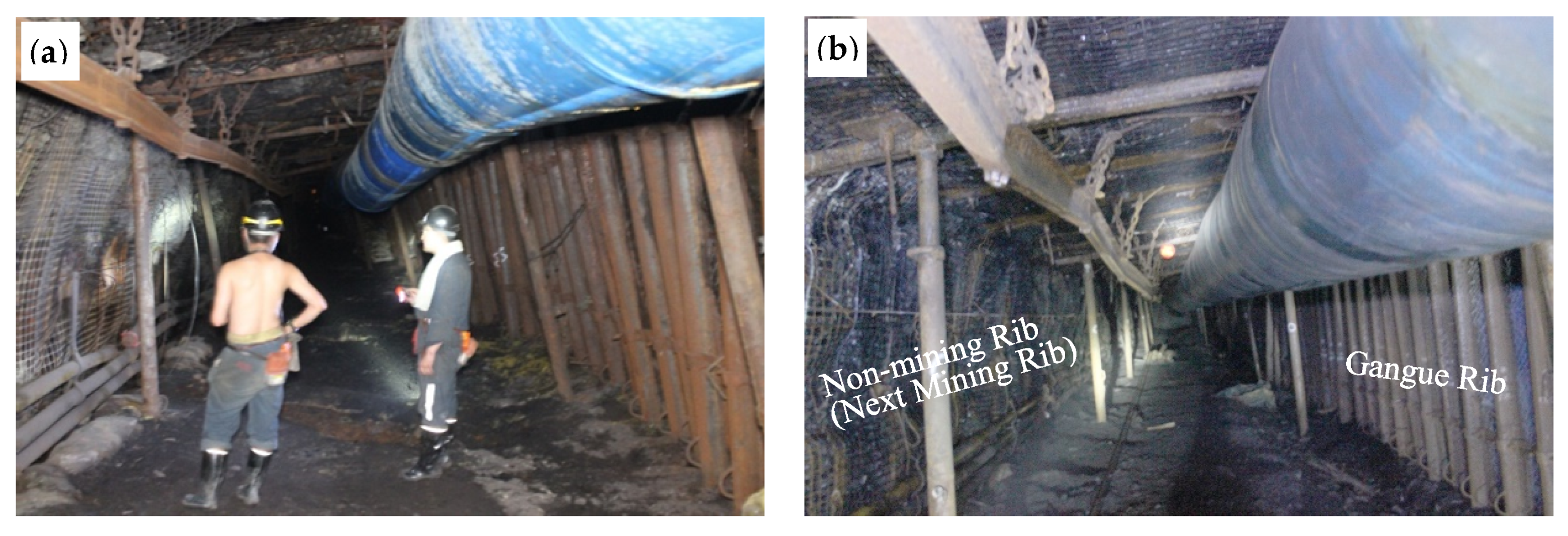
2.2.4. Gangue-Rib Support

Finally, it is necessary to carry out gangue-rib support, not only to prevent the meteorite from flowing into the entry, but also obtain a good entry retaining effect (Figure 5a). Based on years of experience with GERRC, the pressure is small in the shallow working face, the surrounding rock deformation is also small, and the gangue rib is mostly equipped with #11 I-beam for support, and the application effect is good in the field. However, the 1906S working face of Fucheng Coal Mine has a depth of 887 m, and the surrounding rock stress is large, so the I-beam often cannot control the deformation of the surrounding rock of the entry.
In a deep, inclined, thick coal seam, U-shaped steel, steel mesh, gangue bag, and antishock devices are used for joint gangue-rib support (Figure 5b,d). The U-shaped shed (Figure 5c) support body, formed by the overlapping of 2 U-shaped pieces of steel, can ensure the axial sliding contraction of the U-shaped steel when the entry roof sinks, and no lateral bending deformation occurs. An antishock device is installed behind the #1 hydraulic support side guard on the outer side of the working face to effectively alleviate the impact of kinetic energy of the upper gangue of the inclined coal seam and ensure the stability of the U-shaped steel support. At the same time, a gangue bag is stacked between the steel mesh and the antishock device, so that the lateral pressure of the vermiculite can be uniformly applied to the U-shaped shed support body to avoid local stress concentration and bending deformation. Using the connecting rod along the entry to connect the U-shaped sheds into a whole can effectively improve the bending resistance of the U-shaped shed.

3. Determination of Depth and Angle in Roof Cutting

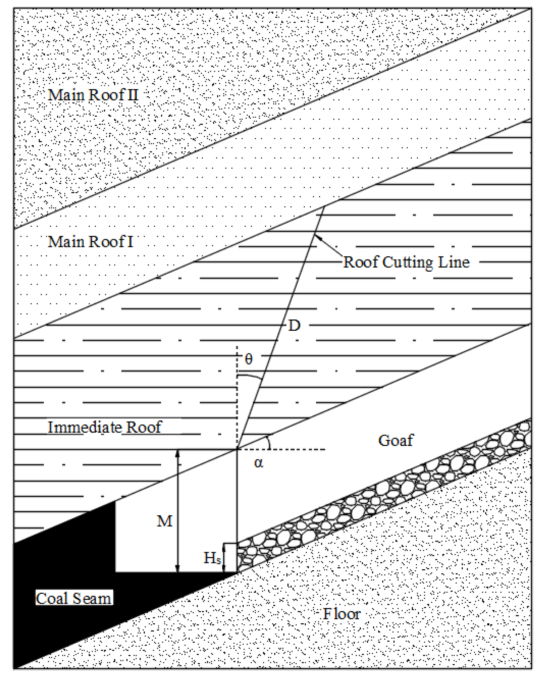
3.1. Mechanical Analysis

GERRC has obvious angle and height effects. Roof cutting requires a certain angle so that the immediate roof of the goaf can directly fall along the precracking surface. On the other hand, reasonable depth of roof cutting can ensure that the fallen gangue fills up the goaf, making the roof of the goaf reach a steady state quickly.

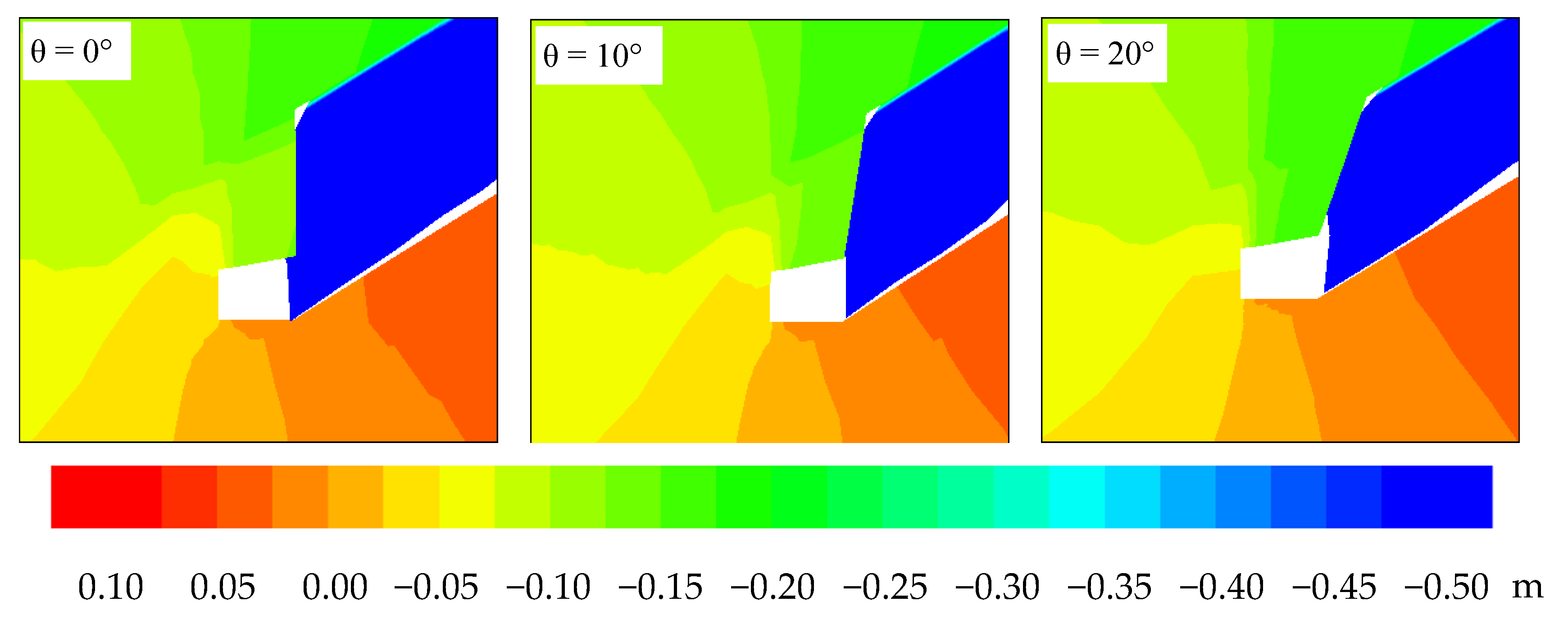
3.1.1. Angle of Roof Cutting

In general, the strength of the immediate roof is low and is further weakened due to the impact of the mining. The effect of the roof cutting angle on the direct roof collapse is small. However, when the immediate roof rock layer is included in the cutting height, if a proper roof cutting angle is not selected, the goaf roof will not fall smoothly, and the goaf rock block outside the precracking surface will still contact the entry roof and squeeze it. This will lead to insufficient pressure relief, and will seriously affect the surrounding rock stability and quality of entry retaining.
As the working face continues to advance, the immediate roof reaches the ultimate span and then breaks into rock blocks. The squeezed broken rock blocks form a stable masonry beam structure due to the horizontal pressing force. After breaking into a curved triangular block, a three-hinged arched balance structure is also formed. Although the immediate roof is broken, mutual inhibition forms a stable masonry structure, and it can still effectively transmit the force to the lateral coal and rock mass, thus affecting the stability of entry retaining. When GERRC is used, the precracking surface becomes the occlusal surface of key blocks A and B (as shown in Figure 6). When key block B is slipped along the cut surface, effective cutting of the stress transmission path can be realized.
The breaking length L of key block B is [30]
L = h d A 2 tan ϕ 0 ln ( k γ H + c 0 tan ϕ 0 c 0 tan ϕ 0 + p x A )
where hd is the entry height (m), px is the coal support resistance (MPa), c0 is the cohesion of the coal seam interface (MPa), φ0 is the internal friction angle (°), k is the stress concentration factor, H is the depth of the entry (m), γ is the average bulk density of the overburden (KN/m3), and A is the lateral pressure coefficient.
The rotation angle of key block B at the beginning of the touch is [31]
θ 0 = arcsin ( M H 1 ( K 1 ) S 0 L )
where M is the mining height (m), K is the direct expansion coefficient, H1 is the direct top thickness (m), θ0 is the rotational inclination of key block B (°), and S0 is the sinking amount of the basic top at the fracture (m).
If θθ0, it indicates that key block B has not fallen. If θ > θ0, it indicates that key block B has fallen. Therefore, when the cutting angle θθ0, the structure of the three-hinge rock block cannot be balanced, and the immediate roof rock block can be smoothly cut along the precracking surface to form the gangue rib. However, the increase of the cutting angle is indirectly equivalent to increasing the length of the lateral cantilever of the top plate, which is not conducive to maintenance of the entry retaining. In the case that the immediate roof rock block can fall smoothly, the roof cutting angle should be reduced as much as possible.

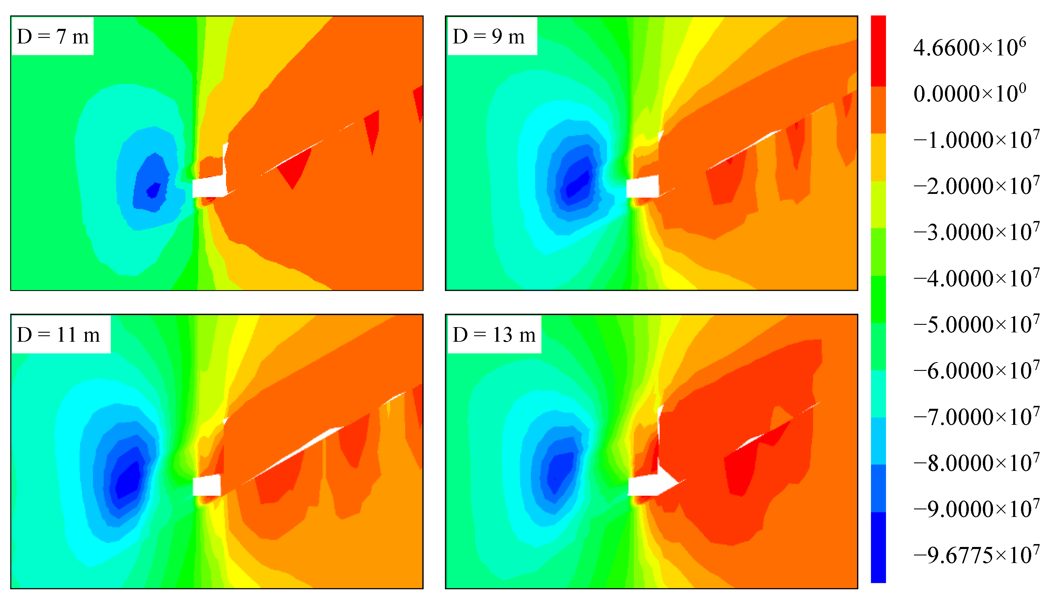
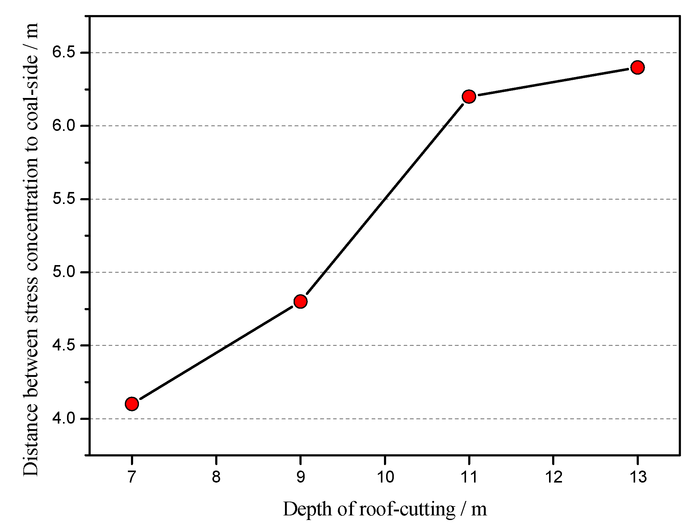
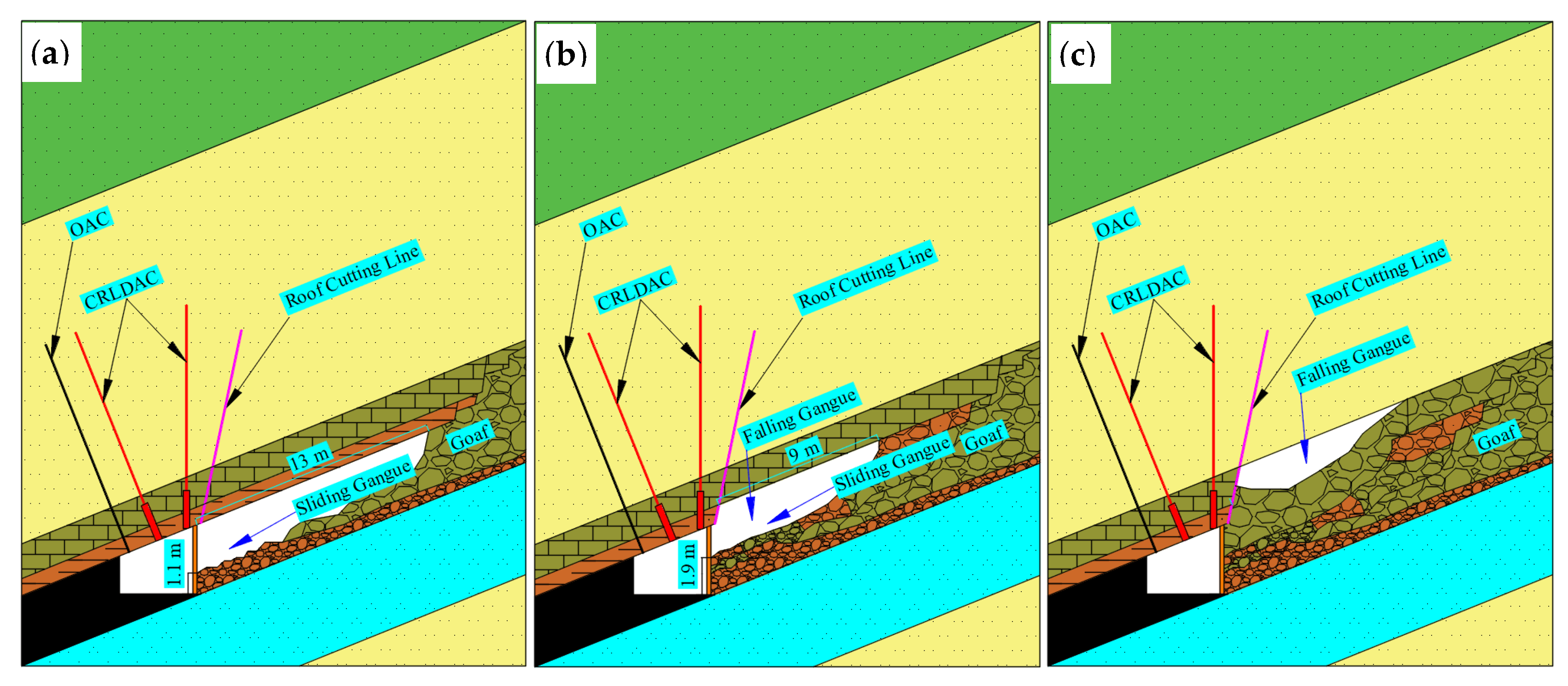
3.1.2. Depth of Roof Cutting

Determining a reasonable roof cutting depth (Figure 7) so that the roof cutting rock layer can fill the entire goaf, which plays a better supporting role for the upper rock layer, will optimize the roof structure of the entry. To minimize the disturbance effect of the roof sagging and sinking on the entry, the surrounding rock stress along the empty entry is effectively improved, and its stability is also significantly improved.
D = M H s ( K 1 ) ( cos θ sin θ tan α )
where Hs is the filling height of the slip gangue (m), K is the coefficient of expansion of the immediate roof rock, usually 1.3 to 1.5, and α is the dip angle of the coal seam (°). The other parameters are the same as before.
As the dip angle of the coal seam increases, the volume of the vermiculite fill above the working surface increases correspondingly; that is, Hs increases, which is conducive to the stability of the overlying strata. The goaf area is directly tilted at the top, and the effective fall volume of the direct top is reduced. Therefore, the influence of the change of coal seam inclination on the filling effect of vermiculite should be considered, and a reasonable depth of cutting should be determined.

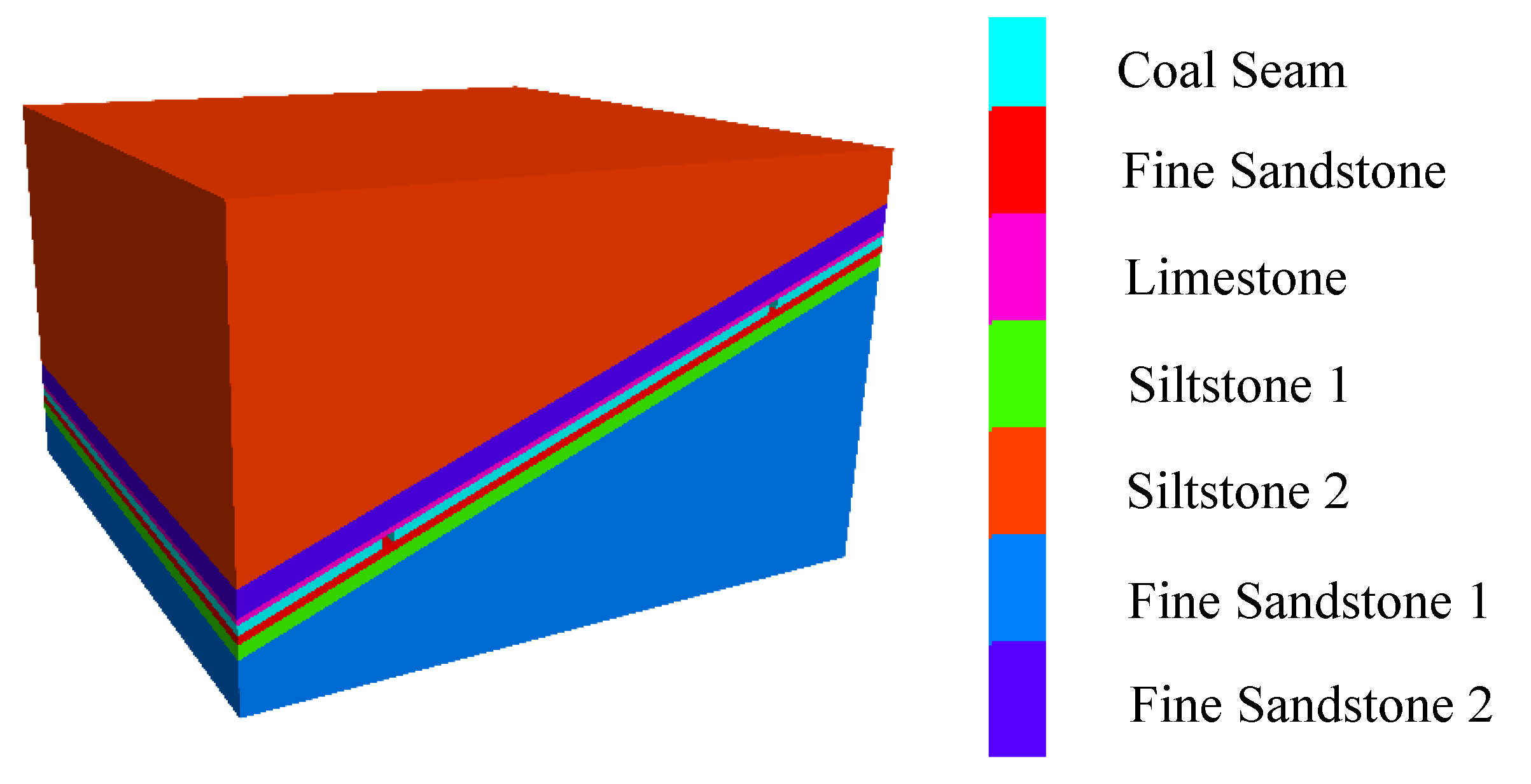
3.2. Numerical Model

The numerical model was constructed based on considering the actual engineering conditions and simplifying the calculation, according to the production geological conditions of the 1906S working face returning entry in Fucheng Coal Mine. The average buried depth of the entry is 887 m, which is driven along the roof of the coal seam; the bottom-to-top lithology and thicknesses are: mudstone 0.3 m, limestone 2.6 m, fine sandstone 12.2 m. The coal seam floor is 3.89 m for fine sandstone and 6.4 m for siltstone. The calculation model was established by using FLAC3D numerical simulation software. The constitutive model was selected by the Mohr–Coulomb model. The model size is 300 × 300 × 200 m (length × width × height). The simulated tunnel excavation size is 5 × 300 × 4 m, and the working face excavation size is 100 × 200 × 4 m. The left and right boundary displacement was fixed in the x-direction, the front and back boundary displacement was fixed in the y-direction, the bottom boundary displacement was fixed in the z-direction, and the upper boundary applied a uniform self-heavy stress. The concrete model rock layer mechanical parameters are shown in Table 1, and the calculation model is shown in Figure 8. The established calculation model was used to simulate the stress-displacement distribution characteristics of surrounding rock under different roof cutting depths and angles.

3.3. Results and Discussion
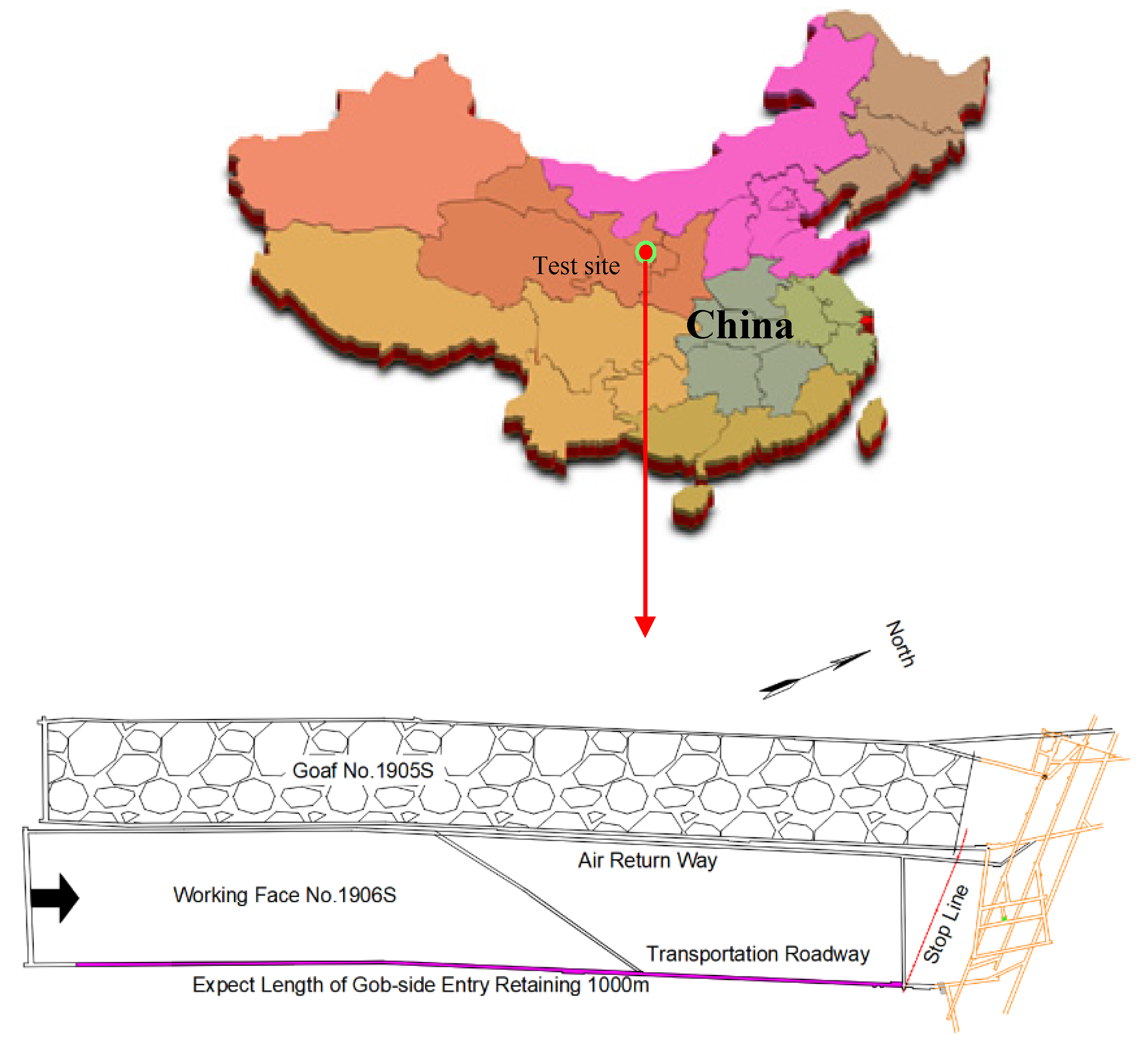
The roof precracking along the entry can effectively cut off the stress transmission between the roof of entry and goaf and reduce the mining stress of the entry roof. As the roof cutting depth increases from 7 m to 11 m, the pressure in the entry roof gradually decreases and is unevenly distributed along the entry section. The pressure near the side of the precracking surface is large, and the pressure near the roof of the coal rib is small. The variation and uneven distribution of the roof pressure is due to the formation of the cut-off short arm beam structure after precracking. When the roof cutting depth is 13 m, the lateral pressure generated by the fallen meteorite in the goaf increases, resulting in an increase in the entry roof pressure (Figure 9).
As the roof cutting depth increases, the thickness of short arm beam increases, and the coal rib changes from the stress rise zone to the stress reduction zone. When the cutting depth is 7 m, the maximum stress is 4.1 m away from the coal rib. When the cutting depth is 9 m, the maximum stress is 4.8 m away from the coal rib. When the cutting depth is 11 m, the maximum stress is 6.2 m away from the coal rib. When the cutting depth is 13 m, the maximum stress is 6.4 m away from the coal rib. As the roof cutting depth increases, the stress concentration zone shifts deeper (Figure 10) while moving upward.
Looking at Figure 11, the following conclusions can be drawn: The roof cutting angle increases from 0 to 20°, the length of the short arm beam increases, the thickness decreases relatively, and the amount of roof sinking increases. Due to the increased roof cutting angle, the shearing force of the entry roof caused by goaf roof falling is reduced, and the separation value of the entry roof is gradually reduced, which is beneficial to the stability of the entry roof. With the increased roof cutting angle, the support force of the gangue in the goaf on the short arm beam increases, which effectively reduces the supporting pressure and the vertical deformation of the coal rib. This is conducive to the stability of the surrounding rock of the entry.

4. Field Test

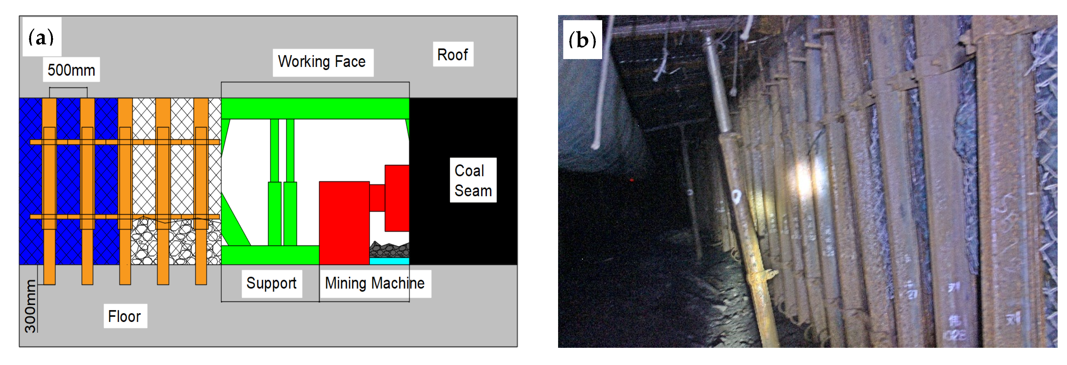
4.1. Field Conditions and Construction Processes

Fucheng Coal Mine is located in Erdos City, Inner Mongolia Autonomous Region, China. GERRC was tested at the 1906S working face. The thickness of the coal seam is 3.55 m and the mining height is 4 m. The working face is buried 841–932.3 m, the coal seam inclination angle is 22–32°, the average inclination angle is 28°, the working surface incline length is 190.3 m, the advance length is 1178 m, and the expected length of entry retaining is 1000 m. The location of the Fucheng Mine and the layout of the 1906S working face are shown in Figure 12.
The whole GERRC construction process was divided into four steps:
Step 1: On the basis of the original support, three cables were added to the 1906S transporting entry roof: two constant resistance large deformation anchor cables (CRLDACs) and one ordinary anchor cable (OAC). The anchor cable diameter was 21.8 mm and the length was 11,300 mm. The diameter of the constant resistance device was 65 mm, the constant resistance value was 33 ± 2 t, the length was 500 mm, and the pretightening force of the constant resistance anchor cable was greater than 25 t. The layout of the two constant resistance deformation anchor cables was as follows: the first row was in the vertical direction, 500 mm away from the mining coal, row spacing was 1000 mm, and a W steel strip was connected (parallel to the entry) to adjacent anchor cables to improve the overall strength of the top plate. The second row of the anchor cable vertical top plate was located in the lane, with a row spacing of 2000 mm. The third column was the ordinary anchor cable in the direction of the vertical roof, 500 mm away from the nonmining coal rib, and the row spacing was 3000 mm. The prefabricated tray of the anchor cable was 300 × 300 mm, the diameter of the intermediate reaming hole was 80 ± 1 mm, and wood was added to the uneven roof. The design, plane, and construction of the constant resistance anchor cable are shown in Figure 13.
Step 2: The blasthole was arranged at the corner between the entry roof and the mining rib. The angle between the vertical line and the blasthole was 20°, the blasthole depth was 11 m, and the distance between the blastholes was 500 mm. The energy collecting tube had an outer diameter of 42 mm, an inner diameter of 36.5 mm, and a length of 1500 mm. The explosive used two-stage coal mine water rubber explosives. The specifications of the explosives are as follows: Φ27 × 400 mm volume, the mass of one roll was 320 g, and the blasting orifice was sealed with yellow mud. Field blasting tests were conducted, and a reasonable charge structure of 2 explosives + 2 explosives + 1 explosive + 2 explosives + 1 explosive + 1 explosive and a stemming length of 2.5 m were determined. After the blasting, the cracks in the blasthole were obvious, and the crack rate exceeded 80%. The goaf roof successfully fell along the precracking surface after mining (Figure 14).
Step 3: The entry roof of the section affected by dynamic pressure adopted the two orthogonal single hydraulic shed for temporary support. Along the direction of the entry section, a single hydraulic shed of one beam and four columns was arranged; the spacing of the columns was 2000, 1000, and 600 mm, and the row spacing was 800 mm. On the gangue rib side, along the entry, a single hydraulic shed of one beam and three columns was arranged, which was close to the U-shaped shed with column spacing of 1200 mm. After mining the working face, the temporary support was arranged in the entry to effectively control the entry deformation between roof and floor (Figure 15).
Step 4: On the gangue rib side, the U-shaped shed, steel mesh, ochre bag, and antishock device were used for joint support. From the outside to the inside, two overlapping pieces of #36 U-shaped steel lap formed a retractable U-shaped shed; the upper part supported the entry roof, and the lower part was buried 300 mm below the floor. The length of the U-shaped steel was 3.3 m and the two pieces were connected by two pairs of clips. The upper and lower edges of the clips were 50 mm away from the U-shaped steel overlapping joint; the overlapping length was 2 m and the clips’ torque was 200 N·m. Steel mesh was bundled together with the U-shaped steel with wire, and a layer of high-strength plastic cloth was arranged between the two layers of steel mesh; a 0.5 m thick gangue bag was arranged at the edge of the steel mesh; and an antishock device was stuck to the gangue bag. Through the joint support, the gangue rib was neat and stable and the deformation was small (Figure 16).

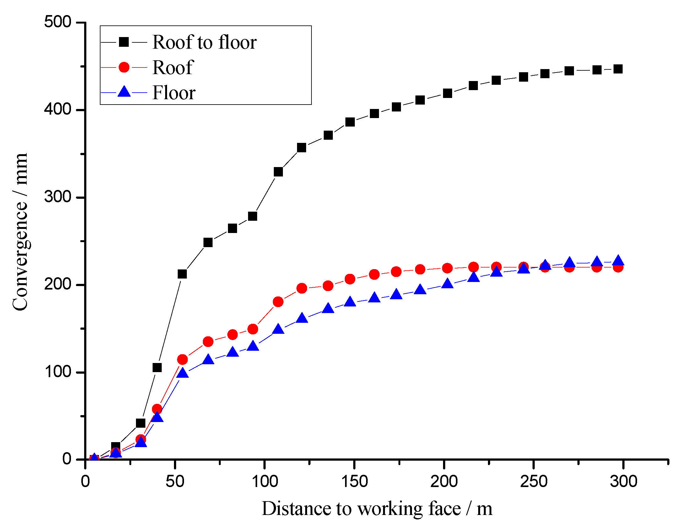
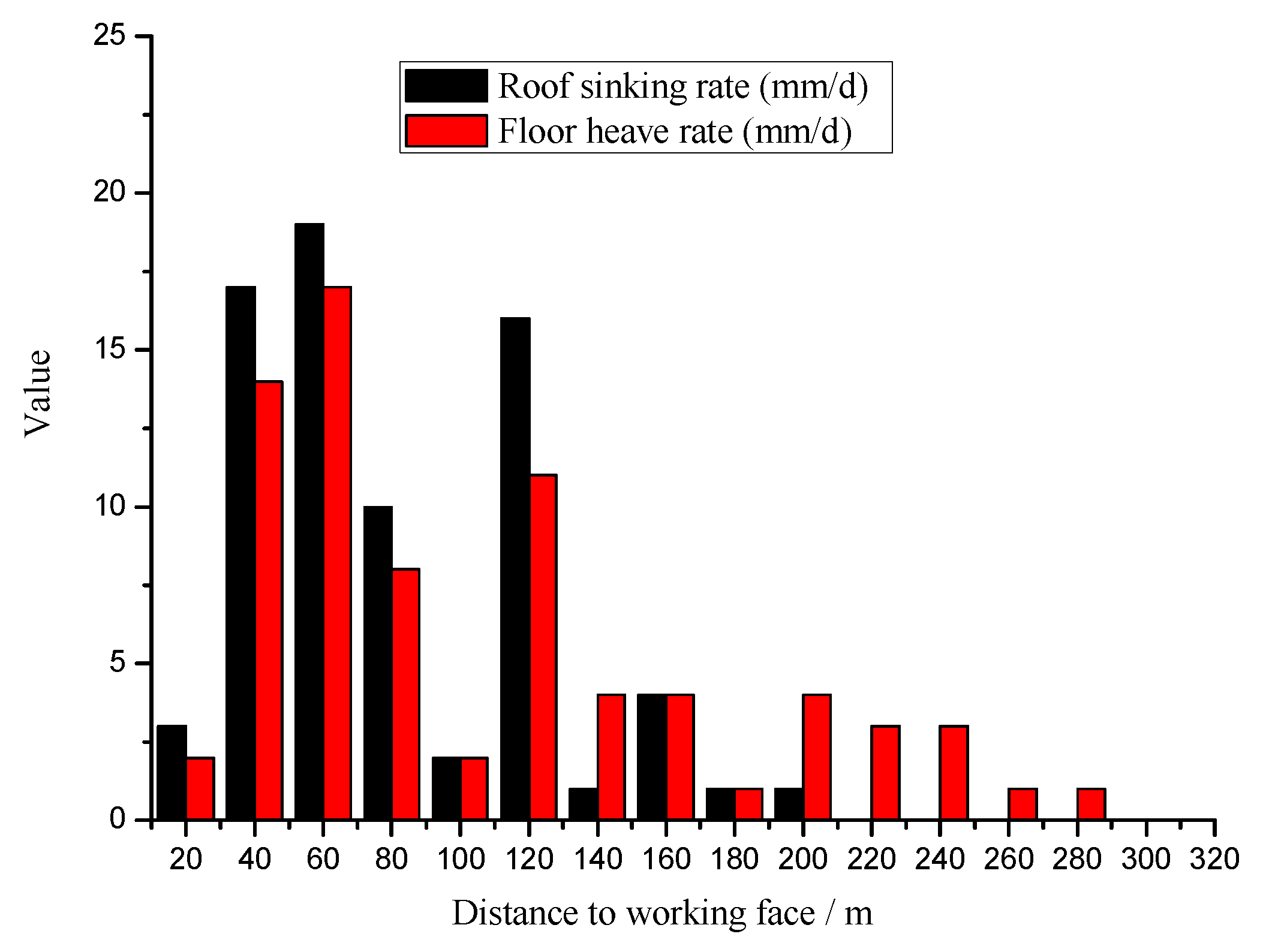
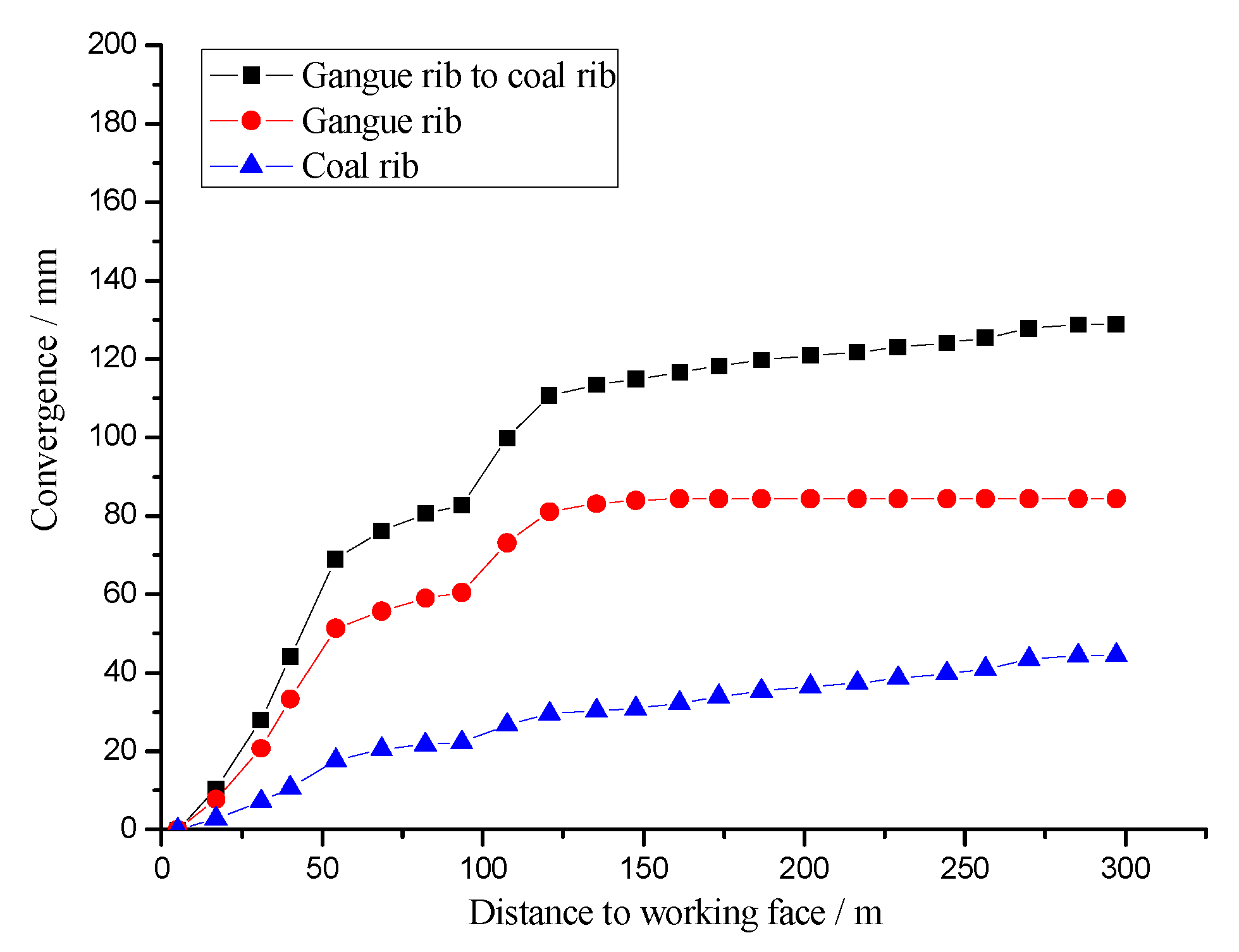
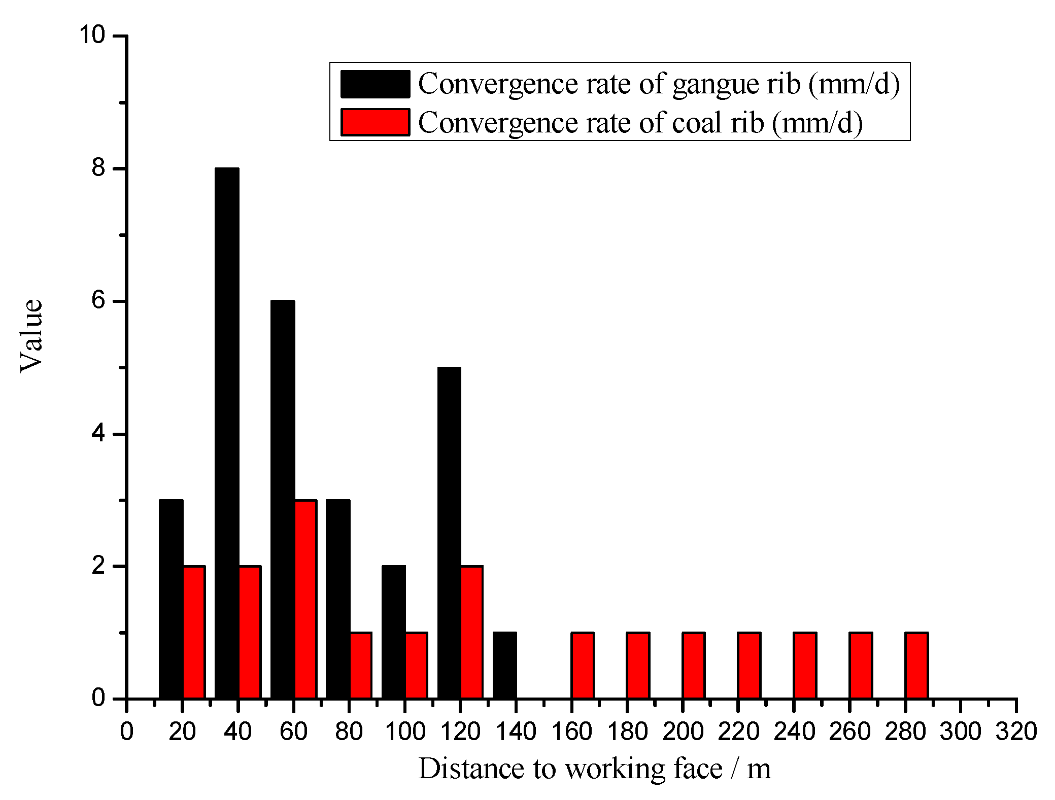
4.2. Deformation and Result of Entry Retaining

The curve obtained by the deformation monitoring of roof to floor and roof and floor are shown in Figure 17 and Figure 18.
(1) The convergence of roof to floor was 447 mm, of which the roof sinking amount was 220 mm, accounting for 49.2% of the total, and the floor heave was 227 mm, accounting for 50.8%. It can be seen that roof sinking accounted for almost the same proportion as floor heave.
(2) From 20 to 60 m behind the working face, the roof sinking rate was more than 10 mm/day, which indicates that the entry roof movement was the most severe. The roof sinking rate of 19 mm/day was at its maximum from 40 to 60 m. From 60 to 100 m behind the working face, the roof sinking rate was gradually reduced to 2 mm/day, and the entry roof tended to be stable. From 100 to 120 m behind the working face, the roof sinking rate started to rise again to 16 mm/day, and the entry roof again moved severely. From 120 to 160 m behind the working face, the roof sinking rate was gradually reduced. When the distance behind the working face was more than 160 m, the roof stayed stable.
(3) From 20 to 120 m behind the working face, the trend of floor heave was almost the same as that of roof sinking. When the distance behind the working face was 120 to 280 m, the floor heave rate was gradually reduced. When the distance behind the working face was more than 280 m, the floor kept stable.
The curves obtained by deformation monitoring of gangue rib to coal rib, gangue rib, and coal rib are shown in Figure 19 and Figure 20.
(1) The convergence between the two ribs of the entry was 129 mm, in which the gangue rib (mining rib) moved close to 84 mm, and the coal rib (nonmining rib) moved to 45 mm. The amount the two ribs moved was small, and the gangue rib moved twice as much as the coal rib.
(2) From 20 to 60 m behind the working face, the convergence rate of the gangue rib was more than 5 mm/d, which indicates that gangue rib movement was quickest; the maximum speed was in the 20–60 m section, at 8 mm/day. From 60 to 100 m behind the working face, the gangue rib movement was gradually reduced. From 100 to 120 m behind the working face, the gangue rib movement started to increase again, equal to 5 mm/day. From 120 to 160 m behind the working face, the gangue rib movement gradually decreased. When the distance behind the working face was greater than 160 m, the gangue rib stayed stable.
(3) From 20 to 60 m behind the working face, the coal rib movement rate was large, which indicates that the coal rib was the most severe. From 60 to 100 m behind the working face, the coal rib movement rate gradually reduced. From 100 to 120 m behind the working face, coal rib movement rate began to increase again, to 2 mm/day. From 120 to 180 m behind the working face, the coal rib movement gradually decreased. When the distance behind the working face was greater than 280 m, the coal rib kept stable.
The surrounding rock deformation of the entry was very small; the maximum deformation amount of the roof was 461 mm, and the maximum deformation of the two ribs was 254 mm. The entry roof had good integrity and there was no obvious failure in the coal rib. The effect of entry retaining is shown in Figure 21. After surrounding rock deformation of the entry was stabilized, the retaining entry had an average width of 4.2 m and a height of 3 m. The entry met the requirements of the next working face for transportation, ventilation, and pedestrians.
The technology was successfully tested in Fucheng Coal Mine and brought significant economic benefits. It saved 28,000 tons of coal and generated 3.9 million yuan in benefits. The 1906S working face transportation retaining lane was used as the 1907S working face return airway, reducing the tunneling entry by 1000 m and saving 7 million yuan in tunneling cost. The overall economic benefit of both totaled 10.9 million yuan.

5. Discussion

In order to observe the filling process of the gangue rib, it is monitored and recorded in real time during the mining process. With the continuous advancement of the working face, the filling height of the gangue rib is monitored.
When the working face advanced 2 m, the filling height was 1.1 m, the roof of the gangue rib in the goaf did not fall, and the hanging width was 13 m (Figure 22a). When the working face advanced 9 m, the roof of the gangue rib in the goaf began falling, the filling height was 1.9 m, and the hanging width was 9 m (Figure 22b). When the working face advanced 17 m, the filling height exceeded the entry height (Figure 22c). The filling process of the gangue rib can be divided into three stages:
(1) The sliding filling stage: The filling gangues only included sliding gangue. Sliding gangue provides support for the goaf roof, controls its continuous deformation, and ensures its stability. By increasing the time of this stage and the sliding filling height, the roof cutting depth can be reduced.
(2) The sliding filling and falling filling stage: The filling gangues include the sliding gangue and the falling gangue. The effect of directional presplit blasting determines the advance or delay of this stage. It is the goal of this stage to make full use of the last stage and timely cut off the roof. If the crack ratio in the lower part of blastholes is bad while the crack ratio in the upper part of blastholes is good, the goaf roof can fall at the end of the sliding filling stage.
(3) The falling filling stage: The filling gangues only include the falling gangue. At this stage, the final roof cutting process is realized, so that the immediate roof of entry forms a short arm beam structure. The breaking length L of the gangue roof would be reduced due to the supporting effect of the vermiculite, and according to Equation (2), the rotation angle of key block B would increase. So the goaf roof can successfully fall down by increasing the roof cutting angle.

6. Conclusions

In accordance with the technology of GERRC in DITCS, using an antishock baffle can effectively reduce the shock from slipped gangue. Based on the principles of RC, the effect of entry retaining affected by the depth and angle of RC was analyzed.
The mechanics of the GERRC roof indicate that hard roof key block B collapsed passively under the interaction of the goaf gangue and the overlying rock strata; the roof-cutting depth and its angle play a key role in GERRC of DITCS. A roof-cutting model of GERRC was proposed to determine the roof-cutting depth and angle.
Based on the roof-cutting model, analytical results show that the greater the angle, the more easily key block B caves. There is a critical angle θ0, and only when the roof-cutting angle θθ0 can key block B cave successfully. When the dip angle of the coal seam is increased, the effect of the angle on the height of the fallen meteorite and the falling meteorite filling should be considered. Using numerical simulation, the stress distributions and deformation of GERRC with respect to roof-cutting depth and angle can be determined.
Based on the geological conditions of panel 1906S in a DITCS with a limestone roof, the roof-cutting depth was determined to be 11 m, and the angle was 20°. Field measurement indicated that these research results were successfully applied in engineering practice.
It is noted that this model was tested on a DITCS. Further study is needed for steeply inclined or high dipping coal seams. In addition, further research efforts to improve the gangue protection technology are required to popularize the GERRC technique.

Author Contributions

M.H. conceived and designed the research. Z.M. and Y.W. performed the numerical simulation and field tests; J.W. provided theoretical guidance in the research process; J.H. and X.Z. analyzed the data and wrote the paper.

Funding

This research was funded by the National Natural Science Foundation of China grant number no. 51574248, no. 51674265l; and the State Key Research Development Program of China grant number no. 2016YFC0600900.

Conflicts of Interest

The authors declare no conflict of interest.

References

  1. Chen, Y.; Lu, S. Surrounding Rock Control of Coal Mine Roadway in China; China University of Mining and Technology Press: Xuzhou, China, 1994. [Google Scholar]
  2. Tao, Z.; Zhao, F.; Wang, H.; Zhang, H.; Peng, Y. Innovative constant resistance large deformation bolt for rock support in high stressed rock mass. Arab. J. Geosci. 2017, 10, 10. [Google Scholar]
  3. Kang, H.; Lou, J.; Gao, F.; Yang, J.; Li, J. A physical and numerical investigation of sudden massive roof collapse during longwall coal retreat mining. Int. J. Coal Geol. 2018, 188, 25–36. [Google Scholar] [CrossRef]
  4. Zhang, C.; Canbulat, I.; Hebblewhite, B.; Ward, C.R. Assessing coal burst phenomena in mining and insights into directions for future research. Int. J. Coal Geol. 2017, 179, 28–44. [Google Scholar] [CrossRef]
  5. Cao, Y.; He, D.; Glick, D.C. Coal and gas outbursts in footwalls of reverse faults. Int. J. Coal Geol. 2001, 48, 47–63. [Google Scholar] [CrossRef]
  6. Bai, J.; Shen, W.; Guo, G.; Wang, X.; Yu, Y. Roof Deformation, Failure Characteristics, and Preventive Techniques of Gob-Side Entry Driving Heading Adjacent to the Advancing Working Face. Rock Mech. Rock Eng. 2015, 48, 2447–2458. [Google Scholar] [CrossRef]
  7. Han, C.; Zhang, N.; Li, B.; Si, G.; Zheng, X. Pressure relief and structure stability mechanism of hard roof for gob-side entry retaining. J. Cent. South Univ. 2015, 22, 4445–4455. [Google Scholar] [CrossRef]
  8. Tan, Y.; Yu, F.; Ning, J.; Zhao, T. Design and construction of entry retaining wall along a gob side under hard roof stratum. Int. J. Rock Mech. Min. Sci. 2015, 77, 115–121. [Google Scholar] [CrossRef]
  9. Yang, H.; Cao, S.; Wang, S.; Fan, Y.; Wang, S.; Chen, X. Adaptation assessment of gob-side entry retaining based on geological factors. Eng. Geol. 2016, 209, 143–151. [Google Scholar] [CrossRef]
  10. Zhang, N.; Yuan, L.; Han, C.; Xue, J.; Kan, J. Stability and deformation of surrounding rock in pillarless gob-side entry retaining. Saf. Sci. 2012, 50, 593–599. [Google Scholar] [CrossRef]
  11. Zhang, Z.; Bai, J.; Chen, Y.; Yan, S. An innovative approach for gob-side entry retaining in highly gassy fully-mechanized longwall top-coal caving. Int. J. Rock Mech. Min. Sci. 2015, 80, 1–11. [Google Scholar] [CrossRef]
  12. Zhang, G.; He, M.; Yu, X.; Huang, Z. Research on the Technique of No - Pillar Mining with Gob - Side Entry Formed by Advanced Roof Caving In the Protective Seam in Baijiao Coal Mine. J. Min. Saf. Eng. 2011, 28, 511–516. [Google Scholar]
  13. He, M.; Zhang, G.; Guo, Z. Longwall mining “cutting cantilever beam theory” and 110 mining method in China—The third mining science innovation. J. Rock Mech. Geotech. Eng. 2015, 5, 483–492. [Google Scholar] [CrossRef]
  14. Sun, X.; Liu, X.; Liang, G. Research on key parameters of retaining roadway along the thin seam of thin coal seam. Chin. J. Rock Mech. Eng. 2014, 33, 1449–1456. [Google Scholar]
  15. Guo, Z.; Wang, J.; Cao, T. Study on key parameters of automatic roadway with thin coal seam topping pressure relief. J. China Univ. Min. Technol. 2016, 45, 879–885. [Google Scholar]
  16. He, M.; Gao, Y.; Yang, Y.; Wang, Y.; Wang, Y.; Zhu, Z. Engineering experimentation of gob-side entry retaining formed by roof cutting and pressure release in a thick-seam fast-extracted mining face. Rock Soil Mech. 2018, 39, 254–264. [Google Scholar]
  17. Gao, Y.; Yang, Y.; He, M.; Wang, Y.; Gao, Q. Mechanism and control techniques for gangue rib deformations in gob-side entry retaining formed by roof fracturing in thick coal seams. Chin. J. Rock Mech. Eng. 2017, 36, 2492–2502. [Google Scholar]
  18. He, M.; Gao, Y.; Yang, J.; Gong, W. An Innovative approach for gob-side entry retaining in thick coal seam longwall mining. Energies 2017, 10, 1785. [Google Scholar] [CrossRef]
  19. Wang, Y.; Gao, Y.; Wang, E.; He, M.; Yang, J. Roof deformation characteristics and preventive techniques using a novel non-pillar mining method of gob-side entry retaining by roof cutting. Energies 2018, 11, 627. [Google Scholar] [CrossRef]
  20. He, M.; Ma, Z.; Guo, Z.; Chen, S. Key parameters of the gob - side entry retaining formed by roof Cutting and pressure release in deep Medium - thickness coal seams. J. China Univ. Min. Technol. 2018, 47, 468–477. [Google Scholar]
  21. Ma, Z.; Wang, J.; He, M.; Gao, Y.; Hu, J.; Wang, Q. Key Technologies and Application Test of an Innovative Noncoal Pillar Mining Approach: A Case Study. Energies 2018, 11, 2853. [Google Scholar] [CrossRef]
  22. Ma, X.; He, M.; Wang, J.; Gao, Y.; Zhu, D.; Liu, Y. Mine Strata Pressure Characteristics and Mechanisms in Gob-Side Entry Retention by Roof Cutting under Medium-Thick Coal Seam and Compound Roof Conditions. Energies 2018, 11, 2539. [Google Scholar] [CrossRef]
  23. He, M.; Ma, X.; Niu, F.; Wang, J.; Liu, Y. Adaptability research and application of rapid gob-side entry retaining formed by roof cutting and pressure releasing with composite roof and medium thick coal seam. Chin. J. Rock Mech. Eng. 2018, 37, 1–14. [Google Scholar]
  24. Wang, Q.; He, M.; Yang, J.; Gao, H.; Jiang, B.; Yu, H. Study of a no-pillar mining technique with automatically formed gob-side entry retaining for longwall mining in coal mines. Int. J. Rock Mech. Min. Sci. 2018, 110, 1–8. [Google Scholar] [CrossRef]
  25. He, M.; Li, C.; Gong, W.; Sousa, L.R.; Li, S. Dynamic tests for a Constant-Resistance-Large-Deformation bolt using a modified SHTB system. Tunn. Undergr. Space Technol. 2017, 64, 103–116. [Google Scholar] [CrossRef]
  26. He, M.; Gong, W.; Wang, J.; Qi, P.; Tao, Z.; Du, S.; Peng, Y. Development of a novel energy-absorbing bolt with extraordinarily large elongation and constant resistance. Int. J. Rock Mech. Min. Sci. 2014, 67, 29–42. [Google Scholar] [CrossRef]
  27. He, M.; Cao, W.; Shan, R.; Wang, S. New blasting technology-bilateral cumulative tensile explosion. Chin. J. Rock Mech. Eng. 2003, 22, 2047–2051. [Google Scholar]
  28. He, M.; Cao, W.; Wang, S. Bilateral cumulative tensile blasting and its application in shaping blasting of caverns. J. Saf. Environ. 2004, 4, 8–10. [Google Scholar]
  29. He, M.; Zhang, X.; Zhao, S. Directional Destress with Tension Blasting in Coal Mines. Procedia Eng. 2017, 191, 89–97. [Google Scholar] [CrossRef]
  30. Li, X. Principle and Technology of Surrounding Rock Stability Control in Roadway Driving Along Goaf; China University of Mining and Technology Press: Xuzhou, China, 2008. [Google Scholar]
  31. Li, Y.; Zhu, X.; Cai, R. Mechanics Analysis on the Stability of Key Block in the Gob-Side Entry Retaining and Engineering Application. J. China Univ. Min. Technol. 2012, 29, 357–364. [Google Scholar]
Figure 1. GERRC. (a) 3D view of GERRC; (b) profile view of I-I.
Energies 12 00934 g001
Figure 2. Constant resistance large deformation anchor cable (CRLDAC) device and principles: (a) technology of CRLDAC; (b) constant resistance device and tray; (c) assembly of CRLDAC; (d) deformation principle of CRLDAC.
Energies 12 00934 g002
Figure 3. Directional presplit blasting device and principles: (a) directional presplit blasting technology (roof cutting line); (b) connection between energy collecting tubes; (c) initial crack after blasting; (d) coalescent crack after blasting.
Energies 12 00934 g003
Figure 4. Temporary support in the entry.
Energies 12 00934 g004
Figure 5. Gangue-rib support device: (a) location of Gangue-rib support; (b) U-shaped steel; (c) U-shaped shed; (d) antishock device.
Energies 12 00934 g005
Figure 6. Roof structure of gob-side entry retaining by roof cutting (GERRC).
Energies 12 00934 g006
Figure 7. Determining roof-cutting depth.
Energies 12 00934 g007
Figure 8. Numerical simulation model.
Energies 12 00934 g008
Figure 9. Vertical stress cloud diagram of surrounding rock of entry.
Energies 12 00934 g009
Figure 10. Relationship between depth of roof-cutting and stress concentration position.
Energies 12 00934 g010
Figure 11. Vertical displacement cloud diagram of surrounding rock of entry.
Energies 12 00934 g011
Figure 12. Fucheng Coal Mine location and plan view of 1906S working face layout.
Energies 12 00934 g012
Figure 13. Design and construction of anchor cable: (a) profile view; (b) plan view; (c) construction platform; (d) effect of construction.
Energies 12 00934 g013
Figure 14. Design and construction of directional presplit blasting: (a) design of blasthole; (b) charge structure; (c) image of crack inside blasthole; (d) effect of goaf roof falling after blasting.
Energies 12 00934 g014
Figure 15. Design and construction of temporary support: (a) design; (b) construction.
Energies 12 00934 g015
Figure 16. Design and construction of gangue-rib support: (a) design; (b) construction.
Energies 12 00934 g016
Figure 17. Vertical convergence of GERRC.
Energies 12 00934 g017
Figure 18. Vertical convergence rate of GERRC.
Energies 12 00934 g018
Figure 19. Horizontal convergence of GERRC.
Energies 12 00934 g019
Figure 20. Horizontal convergence rate of GERRC.
Energies 12 00934 g020
Figure 21. GERRC effect: (a) 50 m from open-off cut; (b) 200 m from open-off cut.
Energies 12 00934 g021
Figure 22. Filling process of gangue rib: (a) sliding filling stage; (b) sliding filling and falling filling stage; (c) falling filling stage.
Energies 12 00934 g022
Table 1. Basic physical and mechanical parameters of rock.
RockThickness (m)Density
(t/m3)
Bulk
(GPa)
Shear
(GPa)
Friction
(°)
Tension
(MPa)
Cohesion
(MPa)
Siltstone 2202.51617365.95.6
Fine Sandstone 112.22.41112330.73.5
Limestone2.62.199333.71.5
Coal Seam4.01.412300.91.1
Fine Sandstone3.892.099333.71.7
Siltstone 16.42.41112334.62.5
Fine Sandstone 2122.41315384.95.4

