Article

A Contribution to the Geological Characterization of a Potential Caprock-Reservoir System in the Sulcis Coal Basin (South-Western Sardinia)

1
Dipartimento di Ingegneria Civile, Ambientale e Architettura (DICAAR), Università di Cagliari, Via Marengo 2, 09123 Cagliari, Italy
2
Consorzio Interuniversitario Nazionale per l’Ingegneria delle Georisorse (CINIGeo)-Viale Vittorio Emanuele II 244, 00186 Roma, Italy
3
Istituto Nazionale di Geofisica e Vulcanologia, Sezione di Bologna, Via Donato Creti 12, 40128 Bologna, Italy
4
Sotacarbo, Grande Miniera Serbariu SS126, 09013 Carbonia, Italy
*
Author to whom correspondence should be addressed.
Energies 2019, 12(23), 4524; https://doi.org/10.3390/en12234524
Submission received: 2 October 2019 / Revised: 23 November 2019 / Accepted: 24 November 2019 / Published: 27 November 2019

Abstract

:
The results provided by this study contribute to the geological characterization of a potential caprock-reservoir system for CO2 storage in the experimental area of the mining district of the Sulcis Coal Basin (south-western Sardinia, Italy). The work is aimed to improve the knowledge of the petrographic and petrophysical characteristics of the siliciclastic and carbonate geological formations that make up the potential caprock-reservoir system. Core samples from a number of wells drilled in the study area for mining purposes were analyzed especially for texture and physical properties (longitudinal velocity, density, porosity, and permeability). The preliminary integrated petrographic and petrophysical characterizations indicate that the Upper Paleocene to Early Eocene potential carbonate reservoir is heterogeneous but presents suitable reservoir zones for CO2. A preliminary analysis of the potential caprock siliciclastic lithologies of the Middle Eocene to Lower Oligocene suggests that they appear suitable for CO2 confinement. Finally, to account for the stability of the investigated area, an accurate geodynamical study of south-western Sardinia was carried out using global navigation satellite system and advanced differential interferometric synthetic aperture radar methodologies in order to estimate vertical and horizontal crustal displacements. The study area results stable, since it is characterized by surface crustal horizontal and vertical velocities smaller than 1 mm/year and few mm/year, respectively.

Graphical Abstract

1. Introduction

The need to minimize the amount of CO2 in the atmosphere is becoming greater and greater and carbon dioxide capture, utilization, and storage (CCUS) technologies are recognized by the scientific community as one of the essential approaches to contain global warming [1]. CO2 can be captured from several kinds of concentrated sources (e.g., power generation and industrial plants) and, depending on the peculiarity of each specific site, it can be converted into valuable products [2] or permanently stored in geological basins. Consequently, sequestration of industrial emissions in adequate geologic formations—as well as the development of CO2 capture and utilization technologies—has become a current necessity. Several CCUS technologies (such as CO2 capture with amine-based solvents and CO2 injection in depleted oil or gas fields) are currently fully commercial, even though they are still characterized by very high capital and operating costs [3,4]. This is the reason why further technology development is still essential.
Because the geological reality is very complex, it is important to describe it in a multidisciplinary way. Therefore, complementary information can help the acquisition of the knowledge of geological conditions suitable for the injection and storage of CO2 [5,6,7]. In geological areas suitable for CO2 storage, the stability of the land surface must also be checked [7,8] both before injection and during and after storage, which also includes during the characterization of the site.
The evaluation of a CO2 geologic storage site requires a robust experimental database, especially regarding the spatial petrophysical heterogeneities, built on inputs from specific investigations by means of a detailed characterization of the rocks making up the possible caprock-reservoir system. In this way, a reliable model can be built to estimate CO2 storage capacity. In this paper, an integrated analysis of minero-petrographical, physical, and geophysical parameters of the rocks that make up the potential caprock-reservoir system in an experimental area in the mining district of the Sulcis Coal Basin (south-western Sardinia, Italy) (Figure 1) [9,10,11,12] was carried out.
The aim of this analysis was to substantially contribute to reducing the geologic uncertainty both in storage site characterization and in geological and numerical modelling to evaluate the suitability of the study site for pilot-scale CO2 sequestration experimental tests. In the study area, the Middle Eocene to Lower Oligocene Cixerri Fm. made up of siliciclastic continental rocks [13,14,15] has been identified as a potential caprock [9,10,11,12]. The Upper Paleocene to Early Eocene Macroforaminifera limestones and Miliolitico Auct. have been identified as a potential carbonate reservoir in early studies [9,10,11,12,16]. From these studies and mining activities [17], it was identified the carbonate rocks have poor primary porosity, but they are interested in their widespread secondary fracturing. In this framework, we also considered it of interest to examine the carbonate lithologies of Produttivo Auct. in the interval between Miliolitico Auct. and Cixerri Fm. (Figure 2) in order to evaluate their suitability for possible experimental-scale CO2 storage. We would like to point out that the pilot-scale CO2 sequestration experimental tests could be carried out on the southern part of the Sulcis Coal Basin, where an important normal fault zone (Monte Ulmus Fault; Figure 1) causes the deepening towards south of the formations that make up the potential caprock-reservoir system. The deepening is testified by borehole 37–87 (Figure 1) south of the Monte Ulmus fault.
For the integrated petrographic and petrophysical analyses of the potential caprock-reservoir geological formations, 51 samples were considered at dry and water saturated conditions, both from siliciclastic and carbonate rocks, from a number of core wells drilled in the study area (Figure 1) and provided by Carbosulcis S.p.A. This study focused on the effect of cement types, rock fabric, texture, pore type, and size on the physical properties of the rocks, especially the acoustic properties as already proposed in several studies [18,19,20,21,22,23,24,25,26,27]. The relations between acoustic velocity, carbonate rock fabric, and texture are strategic in the interpretation of reflection seismic data or data from acoustic logs [20,28].
The observation carried out under optical and scanning electron microscopy (OM/SEM) analyses were integrated with the mercury intrusion porosimetry (MIP) technique to obtain information, such as the pore size distribution, total pore volume, and bulk and skeletal densities of the study rocks. Besides this information, other important parameters (permeability and tortuosity) were deduced from the MIP analyses. The textural characteristics of the investigated rocks were also compared with the longitudinal velocity in order to analyze the influence of the textural and petrophysical parameters on the propagation of the longitudinal acoustic waves. This analysis is effective in evaluating the possibility of extracting petrophysical information from seismic data and predicting porosity from velocity.
In the investigated carbonate rocks of the potential reservoir, secondary porosity, especially of the fracture and channel types, is dominant with respect to primary porosity and favors fluid circulation. In the carbonate lithologies, the comparison between acoustic velocity (Vp) and thin-section analysis by optical and scanning electron microscopy indicates that the longitudinal velocity is strictly affected by the porosity and textural characteristics of the investigated rocks.
A preliminary analysis of the potential caprock siliciclastic lithologies of the Cixerri Fm. suggests that they are characterized by a discreet heterogeneity of their intrinsic characteristics but, in general, appear suitable for CO2 confinement. However, the conglomerate facies characterized by a friable, porous, and permeable matrix could make the sealing action of the Cixerri Fm. less effective. For this reason, the analysis on a larger number of samples will be expanded to the conglomerates. In the siliciclastic rocks of the Cixerri Fm., the comparison between acoustic longitudinal velocity (Vp) and thin-section analysis indicates that the longitudinal velocity is mainly affected by their composition, type of cement or matrix, sorting, packing, and subordinately porosity.
In order to detect potential present active tectonics, a detailed study of the evolution in time of the surface ground displacement of the selected area is necessary. For this purpose, we suggest the synergistic use of information of a different nature, such as global navigation satellite system (GNSS) and advanced differential interferometric synthetic aperture radar (A-DinSAR), in order to acquire useful knowledge about the stability of the potential geological storage site.
In fact, as is well known in the literature [29,30,31,32,33,34,35,36], high-quality GNSS station vertical and horizontal position time series together with sites aselines time series in addition to multiple SAR images must be used to detect very small (few mm) horizontal and elevation changes even in very large areas as wide as 100 × 100 km2 or more. The extreme sensitivity of these techniques to minimal height and horizontal variation, especially when applied in parallel, means that they can be used to monitor the evolution in time of many geophysical and environmental phenomena.
In this work, to account for the stability of the investigated area, in particular the ground vertical and horizontal component of displacement and deformation, a geodetic study was carried out integrating GNSS and A-DinSAR technologies [31,37,38,39]. Although the broad kinematics of Sardinia and South-Sardinia is mainly known (see, for example, Devoti et al., 2017 [40]), the present work has provided available data for a better understanding of the details of how tectonic motions are accommodated on more regional and local spatial scales and on monthly and daily temporal scales.
In particular, we used the data available and distributed free of charge by some permanent GNSS stations maintained by a number of institutions (Leica Geosystems Italy®, TOPCON POSITIONING ITALY S.r.l.; European Permanent Network, EPN; Agenzia Spaziale Italiana, ASI; and University of Cagliari-Italy), all located around and inside the study area, together with many SAR interferometers computed using imagery from the Sentinel-1 A and B of the European Space Agency (ESA-Copernicus®) C-band satellites. The data of these satellites are made available on the Internet for download free of charge and are useful for measuring and monitoring the temporal evolution of the horizontal and vertical components of local ground surface deformation. The GNSS and DinSAR data analysis indicates that the study area is stable, since the surface crustal horizontal and vertical velocities are smaller than 1 mm/year and a few mm/year, respectively.
All the experimental data acquired during the study represent a useful dataset to aid the geological characterization of the experimental site and to improve the geological and numerical modelling of the area. The research unit will follow to expand on the work presented here and focus on further detailed analyses of some facies of the potential sealing lithologies and reservoir in order to integrate the petrographic and petrophysical studies with the geochemical and geomechanical ones for a complete geological characterization of the study area. The latter will be functional to the installation of a field laboratory and a test site for pilot-scale CO2 injection.

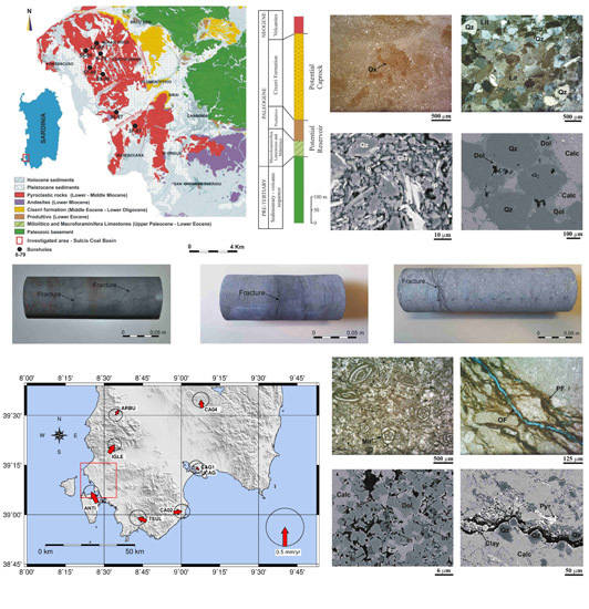
2. Geological Setting

The Sulcis Coal Basin (Figure 1) is located in the south-western sector of Sardinia (Italy). The Sulcis Coal Basin represents one of the most important Italian coal reserves characterized by great mining potential. The stratigraphic succession of the basin is characterized by rocks dating back to the Paleozoic up to the Quaternary (Figure 1).
The Paleozoic lithotypes belong to the Sardinian metamorphic basement considered a residue of the South European Hercynian Chain, which continues through the Provence (France) and Catalonia (Spain) regions [41,42]. In the Sulcis basin, the Paleozoic succession consists of an alternation of conglomerates, sandstones, and claystones intercalated with several volcanic episodes [13]. This volcano-sedimentary succession has been referred to the Permo-Trias. The sedimentary-volcanic Permo-Triassic sequence is covered by a Triassic carbonate succession in Germanic facies [43]. These sequences are overlaid by fluvial sediments and by Jurassic and Cretaceous carbonate complexes present in the island of Sant’Antioco both in the subsoil [44] and the outcrop [45].
During the Paleogene a transgressive-regressive sedimentary cycle occurred. This succession, about 150 m thick, is marine at the bottom and paralic-continental at the top. The first marine sediments are represented by about 40 m of limestones with Macroforaminifera, such as Alveolines and Orbitolites, that date back to the Upper Paleocene–Early Eocene [46]. Over the Macroforaminifera limestones, the fossiliferous content is represented almost exclusively by Miliolidae (Miliolitico Auct.). Above the Miliolitico Auct., approximately 70 m [13] to 90 m [9] thickness, marly limestones and lagoon marls exist with a decreasing salinity environment, with a fossiliferous content represented by Ostracods and Characeae [13], followed by marsh clays and limestones of freshwater with pulmonate gastropods. In the lagoon and marsh levels, several layers of coal are interbedded. This entire sequence is named Produttivo Auct., also called “Lignitifero” [47]. This formation is well documented in several wells that have been drilled by Carbosulcis S.p.A for coal exploration and mining in the area of Carbonia (Sulcis Coal Basin). The Produttivo Auct., which dates back to the Early Eocene [48,49,50], lies directly on the Paleozoic or on the Miliolitico Auct. and is covered by the Cixerri Fm. [51]. The Cixerri Fm. is characterized by terrigenous continental deposits as siltstones, sandstones, and subordinated conglomerates from the dismantling of the Pyrenean chain [14,52,53]. The depositional environment of the Cixerri Fm. is represented by a system of alluvial plains, with proximal characteristics at West and distal at East [52,54]. The age of this formation is between the Middle-Eocene and Lower Oligocene [54].
A large part of the Sulcis basin is characterized by the presence of a wide and thick (up to 900 m) covering of calco-alkaline Miocene volcanites, linked to the detachment of the Sardo-Corso massif from Europe and its counter-clockwise rotation towards east [55]. This volcanic sequence is unconformable on the Cixerri Fm. The sequence consists of volcanic products of dacitic and comenditic composition, mainly in ignimbritic facies and subordinately in lavic facies. This calc-alkaline sequence begins with the emplacement of the dacites and rhyodacites, followed by: (1) an emplacement of pre-comenditic products with rhyolitic composition; (2) comenditic products; and (3) a post-comenditic magmatism with rhyolitic composition [56].
Above the Miocene volcanites, Pleistocene and Holocene sediments have been deposited. The Pleistocene deposits are characterized by alluvial gravels, sands and aeolian sandstones, and alluvial fan deposits that belong to the Portovesme synthem [57], while the Holocene sediments consist of lacustrine sediments, alluvial deposits, and eluvial-colluvial coulters.

3. Data and Methods

3.1. Petrographical and Petrophysical Laboratory Tests

The characterization of the rocks that make up the potential caprock-reservoir system in the study area started from a detailed analysis of both the petrographic and main physical characteristics of the terrigenous continental rocks of the Cixerri Fm. and of the carbonate rocks from the Produttivo Auct., the Miliolitico Auct., and Macroforaminifera limestones.
The physical properties, such as acoustic longitudinal velocity, bulk density, porosity, and permeability, of the rocks under study were analyzed in light of their petrographic characteristics and in particular their texture. Knowledge of the texture is important because of its relationship with the primary and secondary porosity, which affect both the permeability and geomechanical properties of the rocks.
The laboratory measurements were performed on 51 samples provided by Carbosulcis S.p.A., the company responsible for the maintenance of the coal mine in south-western Sardinia, drilled in different boreholes between 370 m and 490 m of depth for the potential caprock, and between 410 to 641 m of depth for the potential reservoir. In total, 34 samples from Produttivo Auct., Miliolitico Auct., and Macroforaminifera limestones and 17 samples from the Cixerri Fm. were considered, representing all major lithologies.
The measurements of the physical properties were performed on regular cylindrical samples of an average length of 20 cm and a diameter of 7 cm [58,59,60]. A part of each was used to prepare both the thin sections for the optical and scanning electron microscopy (OM/SEM) analyses, and a small cubic sample (1.5 cm in size) for the mercury porosimetry injection.
The petrographical characterization of the analyzed lithotypes representing the different facies of the potential caprock-reservoir system was carried out, starting from a detailed analysis of the petrographic features by means of optical and scanning electron microscopy.
For the optical microscopy analysis, the thin sections were impregnated with blue-dye epoxy [27,61] to better visualize the pore space and their connection at the meso-scale [62]. The microporosity and the compositional characteristics, such as the nature of the cement and/or matrix, were evaluated by SEM. The analyzed carbonate rocks were classified according to the depositional texture classification of Folk (1959) [63] and Dunham (1962) [64], while the clastic rocks of the Cixerri formation were classified following Blair and McPherson (1999) [65] and Pettijohn et al. (1987) [66].
The observations carried out under optical microscopy (OM) and SEM analyses were integrated with the mercury intrusion porosimetry (MIP) technique to obtain further information on the porosity of connected pores (effective porosity) and on pore-throat size distributions (radii/diameters), bulk, and skeletal densities. Besides this information, some topological parameters of the pore structure, such as permeability and tortuosity [67,68,69], which depend on the size and arrangement of pores/throats and pore-to-pore connections, were obtained by MIP analyses [70,71,72].
A Micromeritics Autopore IV 9500 (Micromeritics Instrument Corporation, Norcross, GA, USA) to measure the connected porosity for pore-throat diameters in the range 3 nm–360 µm was used. For this analysis, cubes with the largest dimension of about 1.5 cm were prepared and dried at 60 °C for 48 h.
MIP analyses were carried out in two phases: Low pressure (LP) and high pressure (HP). In the LP analyses, the penetrometers were filled with mercury to a maximum of 30 psia and the larger pore throats were invaded by it. In the HP analyses, pressures were increased stepwise from 30 to 60,000 psia. The final pressure value, which allows the mercury to invade pore throats as small as 3 nm approximately, was chosen considering that it is suitable to analyze small pores typical of lithotypes with finer grain sizes.
The longitudinal wave velocities (P-wave velocity) measurements were performed under dry and water saturated conditions and at atmospheric temperature and pressure, following the NORMAL 22/86 guidelines [58].
The experimental device for the acoustic measurements includes a set of ultrasonic transducers with an 82 to 150 kHz central frequency for P waves that propagate along the longitudinal axis of the cylindrical samples. Based on different tests, the range of 82 to 150 kHz frequencies was considered an acceptable compromise between the resolving power and a tolerable attenuation of the ultrasonic signal. For the ultrasonic measurements, the ends of the cylinders were prepared to be free from morphological irregularities, and flat and parallel following the American Society for Testing and Materials (ASTM) guidelines [60].
A portable ultrasonic nondestructive digital indicating tester (PUNDIT LAB Plus) device (Proceq, Schwerzenbach, Switzerland) was employed for the tests. A constant mild contact force was applied during the ultrasonic measurement, and the silicone snug sheets [73] were used to guarantee a good coupling between the transducers and the core sample.
To improve the signal/noise ratio and then the data quality, a stack of 10 waveforms was carried out for each measurement. Then, the transit time of the propagation of the longitudinal ultrasonic signal from the transmitter to the receiver through the samples (direct transmission mode, ISRM 2007, 2014) [59,74] in dry and water-saturated conditions was measured at ambient temperature and pressure. The transit times were measured by locating the first break of the longitudinal-received stacked signal as a result of the analysis of the waveforms recorded and displayed by the portable oscilloscope Fluke 96b [27]. The longitudinal velocity (Vp) was computed considering the ratio between the length of the specimen (L) and the transit time of the longitudinal ultrasonic signal (T). The accuracy of the velocity measurements was ±1%.
The dry and saturated density of the analyzed core samples were calculated as the ratio of the dry and saturated weights to the sample bulk volume. The samples were accurately weighed, and the bulk volume was accurately detected by the caliper method according to ISRM 2007 [59].
The effective porosity (Φeff) data, expressed as the ratio of the connected pore volume (Volp) to the total bulk volume (Vol) [59] of each cylindrical sample, were obtained by the imbibition method using water that accessed only the connected pores within the samples. Each sample was weighed before and after imbibition following the procedure outlined by ISRM, 2007 [59]. Thanks to the difference in weight, given by ρVolp, where (ρ) is the water density considered at ambient temperature, it was possible to calculate the pore volume (Volp). The bulk volume was calculated as already specified for density determinations.

3.2. Geodesy GNSS SAR

3.2.1. SAR-Data

Hundreds of images of Sentinel-1 A and B ESA-Copernicus® (European Space Agency) satellites synthetic aperture radar (SAR), C-band (0.056 m wavelength), Single Look Complex (SLC), image-wide swath (IW), and TOSAR (Terrain Observation by Progressive Scans) were downloaded and saved [75,76]. In particular, the archived images belong to the scenes of the descending 168 track, and of the ascending 88 track, covering an area as wide as 150 × 100 km2 in the time interval lasting from October 2014 to October 2018. The images were distributed free of charge by Copernicus® and the relatives satellites Sentinel-1 A/B are operated and maintained by European Space Agency (ESA). The used SAR imagery illuminates mainly the area of south Sardinia; in this way, we were able to build a robust archive of suitable SAR images.

3.2.2. SAR-Method

In a second step of the procedure, the archived images were processed using advanced DinSAR (A-DinSAR) (differential interferometric SAR) [31,37,77] methodology and ESA Step 6.0 (SNAP-Python module of ESA’s Sentinel Application Platform (SNAP) [78], and GMT5SAR software [79,80]. The two software packages are optimized also for Linux operative systems (OSs) and can operate in the background and using a cluster of central processing units (CPUs). It can an also process TOPS Sentinel-1 A and B data using stochastic algorithms implemented in the Generic Mapping Tools graphic-mathematic library [81,82]. After de-bursting and the application of precise post-calculated orbital information distributed by ESA, the pair of co-registered images illuminating the same scene were stacked to create several interferograms. The data were successively corrected by the phase topographical effect using the SRTM3 (Shuttle Radar Topographic Mission 3) [83] high-resolution (3 arcseconds, 90 × 90 m2) digital elevation model (DEM) of south Sardinia, which can be generated and made available free of charge also using the interactive facility (Generate DEM) provided for GMTSAR users at the web site link: http://topex.ucsd.edu/gmtsar/ [84].
Many interferograms were calculated using the previously described co-registered stack of images pairs that illuminates the same area (scene) in different epochs and corrected for atmospheric noise, filtered and unwrapped using the statistical-cost and network-flow algorithm for phase-unwrapping (SNAPHU) [85,86,87] implemented in the packages, and finally suitably filtered and geocoded.
The time trend of the vertical displacement was computed using the full-resolution interferograms with the technique SBAS (small baseline subset) by differencing the interferograms derived with the application of the above-described A-DinSAR methodology and taking into account only the baselines less than 100 m and 60 days using the data base of all available baselines [31,37].
Many unwrapped DinSAR interferograms of the entire period (November 2014–April 2018) were stacked by selecting the shortest baselines subset (SBAS) following the schemes represented in Figure 3 to compute a velocity pattern of many extended backscatter points 90 × 90 m2 wide. The most significant pixels are characterized by higher reflectivity and were distributed in the study area by projecting the LOS (satellite line of sight) direction on the vertical with the aid of STRM3-computed DEM [83]; the resulting vertical velocities are expressed in mm per year.

3.2.3. GNSS-Data

The RINEX data distributed by Leica-Geosystems for the Italpos/SmartNet GNSS (Global Navigation Satellite System) network [88] and NetGEO (TOPCON POSITIONING ITALY S.r.l.) [89] together with some better quality Euref Permanent GNSS Network (EPN) [90] Italian Space Agency (ASI), International GNSS Service (IGS), and University of Cagliari (Italy) permanent stations (namely, CAG1, UCAG, MATE, NOT1, PADO, ZOUF, GENO, GRAZ, WTZR, and POTS) were used to compute the position time series of some permanent GNSS station sites operating continuously in the Sulcis Iglesiente Region: ANTI, ARBU, CA02, CA04, IGLE, and TEUL corresponding to the Sant’Antioco, Arbus, Senorbì, Pula, Iglesias, and Teulada sites, respectively (Figure 4). We added the previously described permanent network sites to our solutions to define the internal constraints of the analyzed GNSS network, in order to facilitate the robust combination process with SOPAC solutions and to account for the active movements of the study area to be compared later with the A-DinSAR results.

3.2.4. GNSS-Method

A multi-step procedure based on the distributed-sessions approach [91,92,93] was applied starting with the least square adjustment of the GNSS network solutions (hfiles) using the Gamit 10.7 package in order to estimate site coordinates and covariance of the permanent sites [94,95]. The next step in this procedure was to assess the horizontal and vertical velocity of GNSS sites of the Cixerri Sardinian cluster (called CIXE) adjusted in the IGB14 (international core boundary 2014) global reference frame [96], and subsequently the Eurasian Intra-Plate residual velocities. These velocities are represented in Figure 4 with red arrows together with the corresponding error ellipses (area of confidence of the estimated velocities), and the reference velocity of 0.5 mm/year together with the error ellipse of 0.5 mm/year (in black) are represented as a reference in the lower right corner of the figure for a comparison with the velocity vectors of the GNSS network sites. At this stage, the baselines and the baseline component of the GNSS permanent sites of the Cixerri cluster were also computed in order to perform a robust estimate of the vertical and horizontal displacement affecting the study area (Figure 5). The repeatability of the time series of baselines of the Cixerri GNSS cluster was taken into account together with the velocity uncertainties exploited adopting the first-order Gauss–Markov (FOGMEX) estimation procedure suitably implemented by Herring in the corresponding interactive Matlab Tools package [35,36,97].

4. Results

4.1. Siliciclastic Cixerri Fm.

4.1.1. Textural and Compositional Characteristics

The texture and grain composition of the rocks of the Cixerri Fm. were analyzed from the thin sections by OM and SEM analyses. These analyses highlighted that the studied rocks of the Cixerri Fm. are of a siliciclastic nature and heterogeneous in terms of grain size and composition. These lithologies were classified as siltstones, wackes, sandstones, and conglomerates. The siltstones have a pelitic texture, made up of silt granules of different composition: Quartz, calcite, dolomite, and, in some cases, ankerite, all connected by a clay matrix (ranging from 2% to 8%). In many cases, the analyzed samples of siltstones are oxidized (Figure 6a). The sediment is dimensionally well sorted, with particles of silt ranging from 5 to 7 μm (Figure 6b).
The wackes (samples C2-borehole 57–90 and C1-borehole 59–90) have a mud-supported texture and a composition characterized by lithic fragments of calcite and dolomite, crystals of ankerite, and quartz granules, bonded by a silt-clay matrix (Figure 6c). The clay content, about 7% to 10%, denotes a texturally immature sediment, and characterizes the sectors of the rock where the microporosity is concentrated.
The sandstones have a grain-supported texture and are generally made up of sub-rounded grains of carbonate lithic elements and quartz (Figure 6d). Due to the above textural characteristics, these rocks can be classified as litharenites [66]. The grains range from 200 to 500 μm (fine sand to medium sand). A sample of sandstone (C2-borehole 37–87) contains about 10% of K-feldspar (Figure 6e) and can be classified as subarkose [66].
In the sandstones, the binder material is a cement mainly made up of sparry calcite sometimes enriched in dolomite (Figure 6f). However, in a few samples classified as litharenites (C9-borehole 57–90 and C2-borehole 59–90), little amounts (5%) of pelitic matrix not replaced by the cement are still present, indicating a texturally submature sediment. In sample C9-borehole 57–90, pelitic levels are interbedded with well-cemented arenaceous levels. From the SEM analysis, it was observed that the pelitic matrix contains a clay content of about 2%, localized both in some intergranular spaces and within the micro fractures (Figure 6g). At water saturation conditions, sample C9-borehole 57–90 developed swelling phenomena, due to clay–water interaction, and the formation of new fractures. In sample C2-borehole 59–90, the pelitic matrix is confined in the intergranular spaces and is present in isolated spots of the rock. Therefore, in this case, significant swelling or fracturing does not occur as in the previous sample, C9-borehole 57–90. In sandstones, the sutured contacts among the grains ensure tighter packing, which, combined with the low clay content and carbonate cement, causes a reduction in porosity and a tight compactness.
The analyzed conglomerates (samples C1 and C3-borehole 37–87) are less consolidated than the sandstones because they are characterized by polygenic pebbles supported by a friable sandy-pelitic matrix (Figure 6h). In some cases, this matrix can be more compact due to the occasional presence of carbonate cement. According to Blair and McPherson (1999) [65], these rocks can be classified as sandy muddy conglomerates. The presence of fine grains of sand, silt, and clay among the pebbles is typical of poorly sorted and texturally immature sediments.

4.1.2. Thin Section Porosity

Generally, in siliciclastic rocks, the porosity depends on the textural maturity of the sediment, mainly controlled by the depositional process and sedimentation environments [98]. The primary porosity increases as the grain sizes increase, the sediment is well sorted and loosely packed, the grains are rounded, and the clay content decreases. In texturally immature rocks, such as the analyzed wackes, the presence of clay in the intergranular spaces causes a decrease in the primary intergranular porosity. The intergranular clay matrix of the analyzed samples of the Cixerri Fm. is characterized by small primary pores, where the capillary forces prevent the flow of fluids, causing a decrease in the permeability, as also described by other authors [98].
In addition to the primary porosity, the secondary porosity can also affect the sealing effectiveness of a siliciclastic caprock. The development of secondary porosity, generated by mineral dissolution during diagenesis, is ordinary in rocks that contain feldspars (as subarkose sample C2-borehole 37–87) or carbonate lithic elements (litharenites), because feldspars and calcite are dissolved by acidic pore fluids [99].
In general, after deposition, most siliciclastic rocks, in particular sandstones, show a gradual decrease in porosity and permeability with depth [98]. However, also in this condition, the composition of the sediment, mainly in the presence of K-feldspar and calcite, as for the studied Cixerri Fm. lithologies, is the main factor affecting the evolution of secondary porosity especially if the dissolution process dominates.
Except for the conglomerates, most of the analyzed samples of the Cixerri Fm. are characterized by lithotypes with a good degree of compaction and visible porosity values lower than 5%. During the diagenetic processes, these rocks were subjected to compaction, minor K-feldspar dissolution (subarkose), clay minerals growth, and carbonate cementation (sandstones), affecting the primary and secondary porosities.
In the analyzed samples, the primary porosity types are intergranular, intragranular, and interparticle. Small amounts (about 1%) of intergranular pores (Figure 7a), with sizes ranging from 100 to 400 μm (samples C1-borehole 55–90, C1-borehole 62–90, and C10-borehole 57–90), are present in the sandstones. In these lithologies, the carbonate cement is volumetrically significant in the authigenic phase, and therefore the majority of the intergranular spaces is filled by carbonate cement.
An intragranular porosity (<1%), with pore sizes between 2 μm and 100 μm, was also observed in the sandstones. This primary porosity is uncommon, but it can be detected in the individual granules of quartz in the form of resorption gulfs (Figure 7b).
The interparticle primary porosity (1%) is concentrated in the clay matrix of conglomerates, wackes, and siltstones, as shown as examples in Figure 7c and d (samples C2-borehole 57–90 and C1-borehole 59–90). The interparticle pores have sizes of about 1 μm. In these cases, the fine sediment ensures low permeability because the capillary forces hinder the flow of fluids through the small capillaries.
The secondary porosity observed in the Cixerri Fm. is mainly of fracture, intercrystal, and intracrystal types. The fractures (about 1%), 200 nm to 100 μm wide (Figure 7e,f), can be observed in almost all the analyzed rocks. In the sandstones, the rare fractures are located in the carbonate cement while in wackes and siltstones, they are present in the clay matrix. In the conglomerates, the fracture porosity is concentrated in the sandy-pelitic matrix and is interconnected with the interparticle primary pores. The presence of this effective porosity within the heterogeneous and poorly cohesive matrix causes a loss of material, especially when the rock is saturated.
The intercrystal porosity can be observed in some samples of sandstones (samples C1-borehole 55–90 and C1-borehole 62–90), within the carbonate cement, just among the crystals of calcite and dolomite (Figure 7g). The sizes of these pores range between 3 μm and 50 μm.
Intracrystal porosity was observed in the subarkose within the K-feldspar crystals. These pores, ranging between 3 μm and 50 μm, are the product of the alteration and dissolution of the K-feldspar crystals (Figure 7h).
From the results of the OM and SEM analyses, it can be deduced that based on the textural and petrophysical characteristics, the Cixerri Fm. can be considered a potential caprock. In fact, the low porosity values and the presence of intergranular crystalline cement in the sandstones and clay minerals in siltstones and wackes favors the sealing effectiveness of this formation. The efficiency of the sealing action could be less effective in conglomerates characterized by friable and porous matrix. For this reason, the analysis on these lithologies should be enhanced by a larger number of samples.

4.1.3. MIP Analyses.

The curves obtained from MIP analyses, plotted as a logarithm (log) of the differential intrusion volume of mercury versus pore-throat diameter, are shown in Figure 8. This representation highlights the pore-throat size distribution in the analyzed samples.
The main parameters obtained from the MIP analyses are reported in Table 1. The typical patterns of the MIP curves of the Cixerri samples highlight a unimodal distribution of pore-throat diameters.
As an example, in Figure 8a–c, three representative MIP curves of the Cixerri samples are shown. In the MIP curve of the C2 sample (borehole 37–87) shown in Figure 8a, the pore-throat diameters are mainly in the range 0.02–0.20 μm. The MIP curve of the C5 sample (borehole 57–90) shows pore-throat diameters mainly in the range 0.01–0.02 μm (Figure 8b). In the curve obtained for the C1 sample (borehole 62–90), pore-throat diameters are mainly in the range 0.07–0.60 μm (Figure 8c). Considering the entire dataset (Table 1), the median pore-throat diameters, corresponding to 50% of mercury saturation, range from 0.01 μm to 0.23 μm. Pores with the above-mentioned sizes can all be classified as micropores according to Amaefule et al. (1993) [100], Cantrell and Hagerty (1999) [101], and Lønøy (2006) [62].
The measured bulk densities range from 2.38 g/cm3 to 2.66 g/cm3 (Table 1). The skeletal densities range from 2.58 g/cm3 to 2.73 g/cm3 (Table 1). The effective porosity values, from 2.12% to 10.45%, are related to rocks with porosity from negligible to fair [102]. In general, the permeability ranges from values below 0.01 up to 9.17 mD. Only one sample (C2-borehole 37–87) with a permeability of 30.44 mD (Table 1) can be related to rocks with moderate permeability [103]. This permeability value, which is higher than those obtained for the other Cixerri samples, can be related to the weathered conditions of the K-feldspar present in this sample as recognized by SEM analyses. The tortuosity ranges from 1.26 to 69.11 (Table 1). Three samples (C1, C3, and C8) from the borehole 57–90 show the highest tortuosity values (Table 1) and the lowest permeability values (<0.01 mD). In these samples, the tortuosity has a great influence on the interconnectivity of the pore networks. In these conditions, the pore space morphology influences the tortuosity parameter because the presence of very articulate pores can form stagnant pockets that are practically formed by dead-end pores in which the fluids are practically immobile. Moreover, high values of tortuosity together with small-sized pores hinder the circulation of fluids in the rocks.

4.1.4. Acoustic Velocity, Bulk Density, and Porosity

The results of the longitudinal wave velocity (Vp) measurements, bulk density, and effective porosity on the samples of the Cixerri Fm., the potential caprock [12], are given in Table 2. The longitudinal velocities (Vp) for the samples of the Cixerri Fm. that include a spectrum of lithologies, such as siltstones, wackes, sandstones and conglomerates, as can be seen from the optical microscopy (OM) and SEM analyses, range from 3070 to 5162 m/s for dry rocks and from the 2640 to 5344 m/s for water-saturated rocks.
From an integrated analysis between the petrographical characteristics and acoustic properties, it was found that the large variability in the longitudinal wave propagation velocities within the studied rocks of the Cixerri Fm. reflects the variation in their elastic characteristics. The latter are related to the mineralogic composition, the textural characteristics (especially grain contacts, sorting, types of matrix or cement, textural maturity), and the different types of primary and secondary porosity.
The lithologies with the higher velocity, in the range 4860–5162 m/s (Table 2) in dry conditions, are the sandstones classified as litharenites according to Pettijohn et al. (1987) [66]. The high longitudinal velocities are a consequence of the presence of carbonate cement between their grains. Cementation enhances the contact between the rock components, decreasing the porosity and facilitating longitudinal wave propagation. In these rocks, the longitudinal velocity generally increases from the dry to the water-saturated conditions. Only in one sample (C9-borehole 57–90) is a decrease in saturated longitudinal velocity the consequence of the presence of pelitic levels interbedded with well cemented arenaceous levels, as can be seen from SEM analyses. During the saturation process, water causes clay hydration and swelling, with a consequent volume expansion and the formation of new fractures (Figure 9) causing the elastic properties to worsen.
The siltstones are characterized by velocities ranging from 3070 to 4012 m/s in dry conditions (Table 2). Due to their clay content, during saturation, many of the analyzed samples of siltstones (C1, C3, C4, C8–borehole 57–90) underwent a process of disaggregation that did not allow ultrasonic measurements. The samples C5 and C7 of borehole 57–90 are well characterized by the presence of clay minerals among the particles of silt and present a decrease in velocity from dry to saturated conditions. This decrease is due to the fact that in these rocks, during the saturation process, a mechanism of expansion of the clay matrix favored the aperture of fractures worsening their acoustic behavior. This process can also be observed at the macroscale in the above-mentioned core sample C7 (borehole 57–90) after saturation (Figure 10). In the wackes, the velocity values, range 3836–3958 m/s in dry conditions (Table 2), are influenced by the presence of an intergranular silt-clay matrix, typical of a texturally immature sediment. That kind of matrix containing 7% to 10% of clay rich in interparticle porosity does not make a compact self-supporting rock frame and does not allow fast propagation of the longitudinal waves as occurs in the sandstones.
The conglomerates have velocity values ranging from 3100 to 3297 m/s in dry conditions (Table 2). These lowest longitudinal velocity values compared to the other lithotypes of the Cixerri Fm. can be related to their textural characteristics. As a matter of fact, the friable sandy-pelitic matrix between the polygenic pebbles that characterizes the analyzed conglomerates makes a rock frame that allows slower longitudinal wave propagation compared to rocks, such as sandstones, where the presence of the intergranular carbonate cement favors longitudinal wave propagation.
The bulk density of all samples of the Cixerri Fm. ranges between 2.31 and 2.77 g/cm3 for dry samples and between 2.57 and 2.84 g/cm3 for water-saturated samples (Table 2). The measurement of the saturated density was not possible on some samples of siltstones (C1, C3, C4, C8-borehole 57–90), due to their disaggregation during the saturation process as already described in the case of the longitudinal velocity measurements. In all other samples, a general increase in the density values from dry to saturated conditions can be observed.
The effective porosity from the laboratory measurements on core samples ranges from 1.9% to 8.4% (Table 2). The crossplot of the effective porosity (ϕeff) versus saturated longitudinal velocity (Vpsat) is shown in Figure 11. The considerable scattering of the porosity–longitudinal velocity values can be related to the different shape, size, amount, and typology of primary (intergranular, intragranular, interparticle) and secondary (fracture, intercrystal, intracrystal) porosities observed by OM and SEM analyses. However, the petrophysical properties of the siliciclastic lithologies of the Cixerri Fm. and thus the porosity–velocity relations are also influenced by the mineralogical composition (e.g., clay content in the intergranular spaces, quartz, calcite, dolomite, and more rarely, ankerite).

4.2. Carbonate Lithologies (Produttivo Auct., Miliolitico Auct., Macroforaminifera Limestones)

4.2.1. Textural and Compositional Characteristics

In the present study, the mineralogical-petrographic and textural features of the carbonate lithologies underlying the Cixerri Fm. were considered, in light of the different depositional environments that characterize the Sulcis Coal Basin. In this context, a detailed analysis in OM and SEM were carried out on 34 representative samples of the carbonate rocks in order to assess their textural and compositional characteristics. These characteristics together with the porosity and permeability values determined by mercury porosimetry and laboratory measurements on core samples contribute to the evaluation of the efficiency of these materials as a potential reservoir [12].
The Macroforaminifera limestones and the Miliolitico Auct., characterized mainly by whole or broken skeletons of Macroforaminifera (Alveolines and Orbitolites, Figure 12a) and Miliolids (Figure 12b) cemented by sparite and/or dolosparite, can be classified as grainstones [64] or biosparites [63]. From the SEM analysis, it is seen that the same rocks can be classified, from a compositional point of view, as limestones and dolomitic limestones (Figure 12c). In the samples where dolomitization occurred, the dolosparite is characterized by an idiotopic texture (Tucker, 2001) [98] and by an intercrystalline porosity [104] due to the dissolution of the relict calcite as observed in sample C5-borehole 59–90. In all the analyzed samples of the above geological formations, small amounts of accessory minerals (less than 10%) are present. These minerals, such as quartz, clays, and pyrite, are usually accumulated in fractures and stylolites (Figure 12d–f).
The carbonate lithotypes belonging to the Produttivo Auct., located between Miliolitico Auct. and Cixerri Fm. [14], are characterized by a mud-supported texture with a fine-grained carbonate matrix. From the textural point of view, they can be classified as mudstones (Figure 12g) and wackestones (Figure 12h) according to the classification of Dunham (1962) [64] or biomicrites following the classification of Folk (1959) [63]. Their bioclastic components are mainly represented by whole or broken skeletons of Ostracods. These fossils often appear as intact bivalves, which indicates autochthonous deposits of a low energy environment.
From the compositional point of view, the lithologies of the Produttivo Auct. can be classified as limestones, and, in a few cases, as dolostones. These rocks also contain small amounts (<5%) of quartz, clay minerals, and pyrite.

4.2.2. Thin Section Porosity

The physical behavior of the studied carbonate rocks strictly depends on the interaction between the solid phase and the pore network. Generally, in the carbonate rocks, the porosity system manages their permeability and mostly represents the result of depositional history, compaction, and diagenesis, including cementation, dissolution, chemical alteration and clay formation, fracturing, weathering, and dolomitization [98].
In the studied carbonate lithologies, a primary porosity, associated with the original depositional texture of the sediment, and a secondary porosity, related to the post-depositional processes, were distinguished. It should be considered that an original primary pore may be enlarged by dissolution or reduced in dimension by cementation, giving rise to secondary porosity [105].
The SEM analyses highlighted that the primary porosity is more common in the mud-supported limestones of Produttivo Auct.. The pores (Figure 13a), mostly of the interparticle type [104], are located among the particles of micrite that make up the matrix of these rocks. This type of porosity is about 3% on average and the size of the pores is about 2 μm on average.
The interparticle primary porosity is also present in Miliolitico Auct. and Macroforaminifera limestones (Figure 13b), but it is confined within the bioclasts. In this case, the pores range between 100 nm and 1 μm.
The secondary porosity, as intercrystal, intracrystal, intraparticle, moldic, fracture, channel, and vug types [104], predominate in Miliolitico Auct. and Macroforaminifera limestones. The secondary porosity is mainly associated with the carbonate cement and fossil organisms.
The intercrystal pores (Figure 13c) are mainly located in the carbonate rocks where dolomitization processes occurred. The replacement of calcite by dolomite caused an increase in the porosity. The amount of the intercrystal pores is about 2% on average. Their sizes range between 1 μm and 10 μm.
In some samples of Miliolitico Auct., where dolomitization occurred (particularly for samples C3-borehole 6–79 and C5-borehole 59–90), the dolomite crystals are affected by dissolution phenomena that gave rise to intracrystal pores (Figure 13c) of about 1%. Their sizes range between 2 μm and 20 μm. As shown in Figure 13d, the dissolution phenomena and the connection among the intercrystal and intracrystal pores can result in porosity of the channel type (1%).
The fracture porosity (2%) is present in all analyzed carbonate rocks (Macroforaminifera limestones, Miliolitico Auct., and Produttivo Auct.). These fractures can be open or partially filled by terrigenous minerals and oxides (Figure 13e) or totally filled by carbonate cement (Figure 13f). In the mud-supported lithologies of Produttivo Auct., the secondary porosity of the fracture type is interconnected with the interparticle primary porosity. The width of the fractures (200 nm–100 μm) depends on the presence of terrigenous minerals inside them. The presence of accessory minerals, such as clay and quartz, in limestones can increase pore types and weakly increase pore size and fracture aperture [106].
The intraparticle and moldic porosities are mainly present in the lithotypes with high fossiliferous content (wackestones and grainstones) and depend on the dissolution processes of the bioclasts. Partial dissolution of the bioclasts causes intraparticle porosity, while their total dissolution generates moldic porosity (Figure 13g). The small amount of such porosities (about 2%) in the mentioned high fossiliferous rocks points out that the dissolution had a lower impact on porosity than cementation. The sizes of the pores are approximately 40 μm for intraparticle porosity and about 250 μm to 400 μm for moldic porosity.
The vug porosity (1%) is another consequence of the dissolution phenomena that occurred in the analyzed carbonate lithologies (Figure 13h). It is common in mudstones and wackestones and rare in grainstones. The vugs have sizes between 5 and 400 μm.
In synthesis, the pore system of the investigated rocks is very complex both for typology and distribution. The visible porosity is around 12%. Based on the OM and SEM analyses, the carbonate rocks under investigation are relatively compact at the meso-microscale due to carbonate cement in the Macroforaminifera limestones and Miliolitico Auct. and to the carbonate matrix in the Produttivo Auct. However, the secondary porosity of fracture type that affects the carbonate cement and matrix can favor the reservoir role in the above formations. In fact, when the fractures are not totally open, they are partially filled with quartz, pyrite, and mostly clay minerals, which cause a swelling phenomenon and thus an increased fracture aperture.

4.2.3. MIP Analyses

The typical patterns of the MIP curves of carbonate lithologies show a unimodal distribution of pore-throat diameters. As an example, in Figure 14a–c, three representative MIP curves are shown. In the curve obtained for the C3 sample-borehole 6–79 (Figure 14a), the pore-throat diameters mainly fall in the range 0.20–0.70 μm. In the curve referred to C2 sample-borehole 57–90 (Figure 14b), the pore-throat diameters are mainly in the range 0.04–0.25 μm. In the curve relating to C3 sample-borehole 62–90 (Figure 14c), the pore-throat diameters mainly fall in the range 0.02–0.07 μm.
The main parameters obtained by the MIP analyses of carbonate lithologies are summarized in Table 3. The median pore-throat diameters of all the carbonate samples range from 0.01 to 0.42 μm (Table 3). Pores with the above sizes are classified as micropores according to Amaefule (1993) [100], Cantrell and Hagerty (1999) [101], and Lønøy (2006) [62]. The bulk densities range from 2.10 to 2.88 g/cm3 (Table 3). The skeletal density values range from 2.25 to 2.94 g/cm3 (Table 3).
The highest values of densities can also be due to the presence of accessory minerals, such as pyrite. The porosity values, from 0.94% to 20.77% (Table 3), are related to reservoirs with porosity classified from negligible to very good [102]. Permeability, with values lower than 0.01 up to 209.03 mD (Table 3), is related to reservoirs classified from poor to good [103].
A number of samples with tortuosity values from 15.19 to 43.97 (Table 3) are characterized by poor to fair permeability [103]. This highlights the influence of tortuosity on the interconnectivity of the pore networks.

4.2.4. Acoustic Velocity, Density, and Porosity

In Table 4, we report the results of the longitudinal wave velocity (Vp) measurements, bulk density, and effective porosity from the samples of the carbonate lithologies, the potential reservoir [12], underlying the Cixerri Fm.
The velocity values of the longitudinal waves (Vp) in the investigated carbonate lithologies (Produttivo Auct., Miliolitico Auct., and Macroforaminifera limestones) are included in the 4348–6190 m/s range for dry rocks and in the 4641–6580 m/s range for water-saturated rocks (Table 4).
The high variability of the longitudinal wave propagation velocities within the carbonate rocks under examination is linked to the variation in elastic characteristics. From a comparative analysis between longitudinal velocity values and mineralogical–petrographic characteristics of the carbonate lithologies under study, it results that, in general, the longitudinal velocity (Vp) is affected by their fabric [19,20,107,108,109] and, in particular, by the contact between bioclasts, the presence and type of matrix or cement, and the distribution and the type of porosity in the matrix or cement as already observed in previous studies [9,10]. In the grainstones (Miliolitico Auct. and Macroforaminifera limestones), the lower velocities (e.g., samples C8 and C9-borehole 55–90) are a consequence of a secondary porosity mainly of the fracture type (Figure 13e) in their cement while the higher velocity is related to the presence of compact cement, which, by filling the primary and secondary pores (Figure 13f), causes a decrease in the effective porosity. The compact cement enhances the elastic properties of the rock, favoring propagation of the acoustic wave [109]. In the mud-supported limestones of the Produttivo Auct., the lower longitudinal velocities depend mainly on a primary porosity of the interparticle type [104] in their matrix (Figure 13a). These primary pores between the mud particles cannot form a continuous self-supporting frame and consequently, the elastic properties of the rock get worse. In a few cases, the mudstones with a high percentage of dolomite recognized by the SEM analyses (e.g., samples C5 and C6-borehole 55–90) have higher velocities. They are compact with a poor bioclast content and low porosity (1.5–1.6%). In some samples of the mud-supported rocks classified as wackstones [64], the higher proportion of bioclasts (>10%) (Figure 12h) does not favor the propagation of acoustic waves and causes a velocity decrease.
In a few analyzed carbonate samples, both of grainstones and mudstones, the replacement of calcite by dolomite can cause a dolomite cement with low porosity (1.5–1.6%) [18]. This condition improves their elastic behavior and increases the velocity values. In any case, in some other cases, the dolomitization process was observed to increase the amount of secondary porosity of the intercrystal and intracrystal types (Figure 13c), worsening the elastic behavior of the rock. It was also observed that in the investigated carbonate rocks, the longitudinal velocity can be influenced not only by the dolomite content but also by the presence of some accessory minerals, such as clay, quartz, and pyrite (Figure 12d–f), recognized in OM and SEM analyses.
From Table 4, a general longitudinal velocity increase can be observed in the transition from the dry to the water-saturated state of the carbonate samples as well as a wide variability in the saturated velocity values. This variability confirms the wide variation in texture, porosity, and especially shape and arrangement of the pores and in the tortuosity of the investigated carbonate rocks. Only two samples (C2-borehole 57–90 and C6-borehole 59–90) present a decrease in the propagation of longitudinal velocity from the dry to the saturated state. Most likely, this decrease is caused by the presence of stylolites and fractures (see, for instance, Figure 12d) in which residual minerals, mainly clay minerals, were accumulated (Figure 12e). The clay minerals, in the presence of water, can cause swelling phenomena inside the fractures, thus increasing their aperture and the rock volume, with a consequent worsening of the acoustic properties of the rocks, which was also recognized in earlier studies [110,111].
The integrated analysis of the petrographic data with density and effective porosity values (Table 4) performed by the previously described laboratory tests has shown that these parameters are strictly related to the presence and mineralogical composition of the matrix or crystalline cement between the bioclasts. For the carbonate lithologies, the bulk density ranges between 2.57 g/cm3 and 2.77 g/cm3 for dry samples and between 2.61 g/cm3 and 2.79 g/cm3 for water-saturated samples. In general, the density values increase from dry to saturated conditions. It should also be mentioned that in addition to the longitudinal velocity, the density is also influenced by the dolomite content and the presence of some accessory minerals.
The effective porosity was within the range 0.4–9.1%. In general, in the analyzed carbonate samples, porosity does not show a good correlation with the longitudinal velocities. Figure 15 shows the relationship between the saturated longitudinal velocity (Vpsat) and effective porosity (ϕeff). The distribution of the porosity–velocity values for the carbonate lithologies highlights a considerable scattering, indicating a wide variability in the porosity of these rocks. In fact, considering that all the analyzed carbonate samples are characterized by similar mineralogical and chemical compositions, the scattering of the porosity–velocity values can be attributed to the different primary or secondary types of porosity and dimensions of the pores rather than to their compositional differences [18,28,107,112].
In Figure 15, it can also be observed that the carbonate lithologies are characterized by different behaviors, i.e., rocks with similar longitudinal velocities are characterized by different porosity values, while others with more or less the same percentage of porosity are characterized by longitudinal velocities that differ by around 1500 m/s.

4.2.5. Acoustic Impedances

The longitudinal wave velocity (Vp) and the bulk density from laboratory measurements in dry conditions were considered to calculate the acoustic impedances (AIs) (Table 2 and Table 4) of the investigated geological formations. The impedances range from 7.78 × 10⁶ Kg/m2 s to 14.14 × 10⁶ Kg/m2 s in the Cixerri Fm. (potential caprock) (Table 2) and from 11.17 × 10⁶ Kg/m2 s to 17.05 × 10⁶ Kg/m2 s in the carbonate lithologies (potential reservoir) (Table 4). From previous studies [9,10], in the pre-tertiary basement [13] below the potential carbonate reservoir, the acoustic impedances vary from 4.98 × 10⁶ Kg/m2 s to 5.06 × 10⁶ Kg/m2 s. Since changes in acoustic impedance cause the reflection of elastic waves, the great difference of AI between the pre-tertiary basement and the carbonate lithologies can produce good reflections. Therefore, the contact between the lower part of the potential reservoir (Macroforaminifera limestones) and the pre-tertiary Permo-Triassic basement mainly made up of conglomerates, sandstones, siltstones, and claystones can be considered an acoustic marker in the reflection seismic data analysis. On the other hand, it needs to be considered that despite the lithological differences between the siliciclastic Cixerri Fm. and the underlying carbonate lithologies (Produttivo Auct., Miliolitico Auct., and Macroforaminifera limestones), there are no great differences in their acoustic impedance values. Therefore, recognition of the transition from the Cixerri Fm. (potential caprock) to the underlying carbonate lithologies (potential reservoir) in the reflection seismic sections [9] may not be easy.

4.3. Geodynamic Characterization of the Study Area

Geodetic techniques, such as GNSS and DinSAR, are valuable tools for measuring medium-term deformations and also allow the detection of a deformation on a centimeter and millimeter scale of a vast area of territory. As previously described, an integrated application of GNSS and A-DinSAR methodologies was performed to account for the geodynamics active in the study area.
The computed GNSS time series of baselines of permanent stations were taken into account, evidencing very little horizontal and vertical trends, and testifying the stability of the study area as shown in Figure 5. Secondly, the computed vertical velocity obtained after the application of A–DinSAR data processing was taken into consideration, described previously for comparison, which shows good agreement with the vertical velocity of the GNSS permanent stations in the area computed by means of Gamit/Globk 10.7 [94,95] (Figure 16).
As is well known [33,34,35,36,113], a comparison of the GNSS-derived velocities and A-DinSAR computed velocities is needed. As a matter of fact, vertical and horizontal GNSS velocities are stabilized and registered into the [96] ITRF2014 (International Terrestrial Reference Frame 2014) and consequently on the IGS Core Boundary IGB14 [96]. Conversely, the derived vertical and horizontal velocities of the Sentinel–1 A and B images are not stabilized; as a matter of fact, Sentinel–1 A and B vectors are equipped with twin GNSS receivers, and observations are corrected and constrained using suitable precise orbits at the pre-processing level (POD Service). Moreover, spatial geodesy data in general are affected by orbital and tropospheric biases (in particular, the wet part of tropospheric diffraction) that also affect GNSS data, and must be modeled and corrected. Some authors adjust the A-DinSAR data in the least square sense using GNSS observations [35,36,114]; nevertheless, in our opinion, this process must be applied with particular care as it can result in a drastic covering or reduction of the amplitude of environmental effects that need to be better modelled and analyzed.
In the solutions obtained in this study, indeed, the GNSS vertical velocities are in good agreement with the A-DinSAR SBAS (small baselines subset technique)-computed ones (Table 5).
In fact, apart from a little subsidence signal in some areas (100 × 100 m2 pixel), in the plane of Campidano (few mm/year), the city of Cagliari, and the town of Sarroch, where there is a large chemical power plant, values are positive and vary in the 0–2 mm/year range, essentially on account of ground water over exploitation and consolidation of modern urban expansion [115]. Concerning the investigated horizontal movements, as pointed out also by other authors [30,40,91,92,93,116,117,118], it can be asserted that as for the entire Sardinian-Corsican block, the Cixerri horizontal absolute velocities follow the general motion of the Eurasian plate and the intra-plate residual velocities are negligible and always in the range +/–0.3 mm/year. As stated above, the vertical velocities of the south Sardinian cluster are positive and vary between 0 mm/year and 2 mm/year as in the Sulcis-Cixerri area, denoting a good vertical stability in general, except for those few previously described areas that are subjected to subsidence and hydro-geological instability, and where the vertical velocity values are negative and above 2 mm/year to 3 mm/year [40,113].

5. Discussion

As can be deduced from the OM and SEM analyses, the samples belonging to the Cixerri Fm. potential caprock [11,12] are characterized both by a primary porosity formed during the deposition of sediments, and a secondary porosity, which is related to a phase following the lithogenesis and which developed due to fractures and chemical dissolution.
As regards the analyzed samples at least, the Cixerri Fm. is mainly characterized by low values (1–2%) of primary porosity. The reduction in primary porosity is mainly caused by the growth of pore-filling clay minerals, mainly in siltstones, wackes, and conglomerates, and carbonate cementation, mainly in sandstones.
The primary pores in siltstones and wackes are mainly localized in the clay matrix, which, when saturated, hinders the circulation of fluids. Furthermore, the presence of the carbonate cement as a binder material in the sandstones guarantees a high degree of compactness and an effective barrier against the passage of fluids. In the Cixerri Fm., the secondary porosity is characterized by fractures, intercrystal, and intracrystal pores. The fractures are related to physical phenomena and affect the matrix of the siltstones, wackes, and conglomerates and the carbonate cement in the sandstones. The intercrystal and intracrystal porosities depend on chemical processes, such as the incomplete carbonate cementation (intercrystal) in sandstones or the dissolution processes of K–feldspar (intracrystal) in the subarkose. The dissolution phenomenon was exclusively observed in the feldspar crystals of the subarkose sample, while the carbonate lithic elements in the litharenites do not present the effects of dissolution processes. It is noteworthy to point out that the subarkoses are quite rare in the Cixerri Fm. Therefore, based on these observations, in the Cixerri Fm., the cementation processes are predominant over those of dissolution, thus affecting secondary porosity evolution.
The presence of clays in the siltstones, wackes, and conglomerates as well as the intergranular carbonate cement in the sandstones and the low primary and secondary porosity values of the above lithologies facilitate the sealing efficiency of the Cixerri Fm. Moreover, the small sizes of the pore throats measured by MIP analyses and ranging from 0.01 μm to 0.23 μm represent a further obstacle to fluid circulation. In a few samples, the fluid circulation is also hindered by high tortuosity values that influence the interconnectivity of the pore network and thus rock permeability. Moreover, these characteristics are in agreement with the results of a hydrogeological study where the Cixerri Fm. was defined as impermeable [119].
Based on these characteristics, the Cixerri Fm. could be considered a potential caprock. However, the sealing action of this formation could be made less effective by the conglomerates that are characterized by a friable, porous, and permeable matrix, as observed from the SEM and OM analyses. For this reason, the analyses on the conglomerates should be enhanced with a larger number of samples.
As deduced from the analyses of samples from different boreholes in the study area, the variations in the elastic properties of both dry and water-saturated siliciclastic rocks of the Cixerri Fm. are linked to variations in textural maturity, different types of porosity, sorting, packing, mineralogical composition (mainly clay content), and cementation. The clay content and the presence of intergranular carbonate cement play an important role in the porosity and propagation of the acoustic signals. The investigated relationship between porosity and acoustic velocity present a wide scattering despite the small porosity range (1.9% to 8.4%) detected in the laboratory measurements on the core samples. Consequently, if this condition should be confirmed by further studies on a larger number of samples, the use of the seismic velocities to build a porosity distribution model for the Cixerri Fm. could be critical. This subject will be the topic of further research. It is important to emphasize that the textural differences between the lithologies of the siliciclastic Cixerri Fm. exert a great influence on their acoustic behavior and determine the considerable spatial heterogeneity of this formation. This is to be carefully considered in the geological and numerical modelling of the study area (Sulcis Coal Basin) in order to evaluate the caprock reservoir system quality.
As regards the grain-supported carbonate lithologies (Macroforaminifera limestones and Miliolitico Auct.), which is a potential reservoir, the interconnected porosity is mainly of the secondary type, because the primary porosity was reduced by cementation and compaction during post-depositional burial. These secondary pores affect the carbonate cement, especially through fractures, which may be partially filled by allogenic minerals, such as quartz, or by authigenic minerals, such as clay and pyrite. Due to its attitude to swelling in the presence of water, clay especially can increase the fracture width, worsening the elastic characteristics of the rock, as observed in some analyzed samples.
On the other hand, a number of fractures filled with carbonate cement suggests that the old crack system was well interconnected and allowed the passage of saturated calcite fluids. These fluids determined a cementation and therefore a partial occlusion of the porous system at the microscale. Cementation favored the local compactness of the rock, and as a result the analyzed samples where the fractures are filled by sparry calcite were characterized by the highest Vp values.
Dolomitization was another factor that influenced the secondary porosity of the studied carbonate lithologies due to the neoformation of intercrystal and intracrystal pores. The interconnectivity between these pores depends on the degree of dolomitization of the rock and influences the effective porosity.
The mud-supported carbonate rocks (Produttivo Auct.) are characterized by a fine matrix mostly affected by a primary interparticle porosity. The interparticle pores are often interconnected with secondary porosities of the fracture and vug types. The interaction between the primary interparticle porosity and the fractures improves fluid percolation. The permeability due to fractures depends on their characteristics, whether they are open or partially filled with accessory minerals, such as clay, quartz, and pyrite, which can increase their aperture. Also, in the Produttivo Auct. lithologies as well as in the Macroforaminifera limestones and the Miliolitico Auct. lithologies, fractures completely filled with calcite are not rare. Based on the above features, the Produttivo Auct. can be considered a potential tight and fine-grained reservoir following Nelson (2009) [120] and Zou (2017) [121] and could contribute to increasing the thickness of the potential reservoir identified in the Miliolitico Auct. [12] and Macroforaminifera limestones.
Despite the fact that OM and SEM analyses detected pores with sizes from 100 nm to around 400 μm, the MIP analyses showed that the pore-throats are generally small, ranging from 0.01 μm to 0.41 μm. Consequently, even large pores can be connected by the small pore-throats. In many samples, the small throats are characterized by high tortuosity values that reduce permeability. Based on the MIP analyses, the values of permeability, which are mostly within the range below 0.01 mD to 10 mD, are related to poor to fair permeability reservoirs [103]. Subordinately, the permeability values that range from 10 mD to 209 mD can be related to moderate to good permeability reservoirs [103]. In conclusion, all the achieved results suggest that the carbonate lithologies are heterogeneous with a generally low permeability, but some zones could be considered suitable reservoir zones [10].
From the integrated analysis of acoustic and petrographical data, especially textural features, it was also observed that pore types and pore sizes are the main factors that affect acoustic wave propagation in the analyzed carbonate lithologies, as already recognized by other authors [18,22,107] in the study of carbonate lithologies. The analysis of the relationships between longitudinal velocity (Vp) and effective porosity and the scatter between the above two parameters is a demonstration of the complexity of this relation and confirms the complexity of the pore network in the studied carbonate lithologies. Such complexity could make it difficult to predict porosity from seismic data.
It should also be pointed out that in the investigated carbonate lithologies, the fractures range from the microscopic scale observed by OM and SEM to the sample scale (see Figure 17) and to the outcrop scale [16,17]. The fault zones detected by geological and geostructural studies [12,14,50] and by seismic interpretation regarding the northern part of the Sulcis Coal Basin [9,10] can act as preferential pathways for fluids, improving the porosity and permeability of the investigated carbonate lithologies. Therefore, the carbonate lithologies take on the characteristics of a reservoir for the purpose of geological storage of CO2, particularly in light of the widespread fracturing related to the fault zones [12].
In an experimental study aiming to characterize a geological context with a potential caprock reservoir system, it is also crucial to know the stability of the investigated area. In this study, the stability of the area under study was confirmed by our analysis. As previously described, the integrated application of GNSS and DinSAR methodologies allows for hypothetical horizontal and vertical displacements presently active in the study area of the Sulcis Coal Basin to be accounted for. Moreover, evidence of the geodynamical stability of this area is provided by the small horizontal intra-plate residual estimated velocities that range in the interval of ±0.3 mm/year. Owing to the resulting feeble and non-significant strain rates characterizing this area, a study of the baseline time series was necessary, and confirms the very small horizontal displacements. Regarding the vertical movements, the integrated application of DinSAR and GNSS methodologies provides comparable vertical velocities ranging in the ±2 mm/year interval, and the resulting negative trends were detected in particular in the coastal areas of the Cagliari town district, where water extraction is probably performed daily for industrial and civilian usage. Conversely, negative vertical trends were not observed in the area of the Sulcis Coal Basin, where a lower vertical velocity trend of about +1 mm/year was observed in the time series of the permanent GNSS station of Sant’Antioco.
It can finally be concluded that the area of the Sulcis Coal Basin is characterized by a great geodynamical stability as for the entire region of Sardinia. As a matter of fact, the closer GNSS permanent stations of Cagliari (CAG1, CAGL, CAGZ, UCAG) have been used in the past and are still used as internal constraints to improve the definition of the European Terrestrial Reference Frame (ETRF).
All the experimental data acquired during this study and the achieved results represent an experimental and useful dataset to aid the geological characterization of the experimental site, in order to improve the geological and numerical modelling of the area, and to analyze any reflection seismic data available.

6. Conclusions

The analysis of all the experimental data acquired during this study provides an essential contribution to the geological characterization of the caprock–reservoir system made up respectively of the Middle Eocene to Lower Oligocene continental siliciclastic Cixerri Fm. and the Upper Paleocene to Early Eocene carbonate lithologies of Macroforaminifera limestones, Miliolitico Auct., and Produttivo Auct. of the Sulcis Coal Basin (SW Sardinia).
The study allowed an evaluation of several petrographical and petrophysical parameters of the potential caprock–reservoir system in the Sulcis Coal Basin. The following points, among others, are important:
The siliciclastic lithologies of the Cixerri Fm are heterogeneous in terms of grain size, texture, and composition. Four representative facies were identified by OM and SEM analyses: Siltstones, wackes, sandstones, and conglomerates;
The Cixerri Fm. lithologies are characterized by a good degree of compaction and low porosity values due to the presence of intergranular crystalline cement in the sandstones and to the clay matrix in siltstones and wackes. These characteristics facilitate the sealing efficiency of the Cixerri Fm. However, the sealing action of this formation could be made less effective by the conglomerates characterized by a friable sandy-pelitic and porous matrix and average permeability values (8.7 mD) greater than the average permeability of siltstones (1.6 mD), wackes (3.3 mD), and sandstones (3.9 mD). For this reason, the petrographic and petrophysical analyses on the conglomerates should be enhanced with a larger number of samples. The investigated relationship of porosity versus acoustic longitudinal velocity reveals a considerable scattering that can be related to the different shape, size, amount, and typology of the primary and secondary porosities and the mineralogical composition of the Cixerri Fm. lithologies;
The carbonate lithologies are heterogeneous in terms of textures and porosity: The Macroforaminifera limestones and Miliolitico Auct. are characterized by grain-supported bioclastic carbonate rocks (grainstones), while the Productivo Auct. is made up of mud-supported bioclastic limestones (mudstones and wackestones). At the microscopic level, the Macroforaminifera limestones and the Miliolitico Auct. lithologies are poor in primary porosity due to their high degree of cementation. The primary porosity is present in the carbonate matrix of the Produttivo Auct. lithotypes and is interconnected to secondary porosity of the fracture type. This condition favors the permeability of the Produttivo. In fact, the average permeability (18.6 mD) of this formation is greater than the average permeability (7.9 mD) of the Macroforaminifera limestones and Miliotico Auct. Consequently, the Produttivo Auct. could contribute to increasing the thickness of the potential carbonate reservoir identified in earlier studies as Macroforaminifera limestones and Miliolitico Auct.
The analysis of the relationships between longitudinal velocity (Vp) and effective porosity and the scatter between the above two parameters is a demonstration of the complexity of this relation and confirms the complexity of the pore network in the studied carbonate lithologies. This complexity could make it difficult to predict porosity from velocity.
In summary, especially, the petrophysical characteristics of the investigated carbonate rocks are low and not attributable to a good-quality reservoir. However, as can be seen from the thin section analyses, from earlier studies, and from mining activities, the presence of fractures ranging from the microscopic scale to the sample scale and to the outcrop scale significantly enhances the permeability of the investigated carbonate lithologies. Therefore, for the purpose of pilot-scale CO2 injection, the latter take on the characteristics of a reservoir, particularly in light of the widespread fracturing related to fault zones.
The integrated application of GNSS and A-DinSAR methodologies allowed the detection of vertical and horizontal velocities in the study area. The small values of the above-obtained velocities demonstrate the geodynamical stability of this region, since the detected velocities were in the interval +/−0.3 mm/year in the horizontal and showed a vertical trend of few mm/year in south Sardinia, and less than 1 mm/year in the study area.

Author Contributions

S.F. and G.C. initiated research ideas. S.F. designed the laboratory experiments, performed the petrophysical and geophysical laboratory measurements on the samples and analysed the data. F.C. performed the OM and SEM analyses and with S.F. performed the integrated petrophysical and petrographic analysis of the data. P.L. analysed the mercury porosimetry data and contributed to the petrophysical analyses. G.C. and M.G.B. processed and interpreted GNSS–SAR data. A.P. (Alberto Plaisant) and A.P. (Alberto Pettinau) took care of the Regional Government of Sardinia (RAS) project administration and funding acquisition. All authors analysed and discussed the results, contributed to drafting the manuscript and preparing the figures. All authors reviewed and approved the manuscript.

Funding

This work was jointly supported by the “Centre of Excellence on Clean Energy” project (CUP: D83C17000370002) funded by the Regional Government of Sardinia (FSC 2014–2020) and by FIR (Fondi integrativi per la Ricerca) funded by the University of Cagliari (Italy).

Acknowledgments

We thank Carbosulcis S.p.A. for supplying the core samples used in this study and we are also grateful to Leica Geosystems S.p.A. Italy for providing some of the GPS data of the Italpos network. We also thank Geotop Italy Topcon/Sokkia, reseller of the GPS data of the NetGEO network used in this work. Some figures in this paper were produced by means of the Generic Mapping Tools (GMT) graphic package.

Conflicts of Interest

The authors declare no conflict of interest. The funders had no role in the design of the study; in the collection, analyses, or interpretation of data; in the writing of the manuscript, or in the decision to publish the results.

References

  1. International Energy Agency. World Energy Outlook 2018; International Energy Agency: Paris, France, 2018. [Google Scholar]
  2. Mureddu, M.; Ferrara, F.; Pettinau, A. Highly efficient CuO/ZnO/ZrO2@SBA-15 nanocatalysts for methanol synthesis from the catalytic hydrogenation of CO2. Appl. Catal. B Environ. 2019, 258, 117941. [Google Scholar] [CrossRef]
  3. Van der Spek, M.; Roussanaly, S.; Rubin, E.S. Best practices and recent advances in CCS cost engineering and economic analysis. Int. J. Greenh. Gas Con. 2019, 83, 91–104. [Google Scholar] [CrossRef]
  4. Cau, G.; Tola, V.; Ferrara, F.; Porcu, A.; Pettinau, A. CO2–free coal–fired power generation by partial oxy–fuel and post–combustion CO2 capture: Techno–economic analysis. Fuel 2018, 214, 423–435. [Google Scholar] [CrossRef]
  5. Hermanson, J.; Kirste, D. Representation of Geological Heterogeneities and Their Effects on Mineral Trapping During CO2 Storage Using Numerical Modeling. Procedia Earth Planet. Sci. 2013, 7, 350–353. [Google Scholar] [CrossRef]
  6. Nakajima, T.; Ito, T.; Xue, Z. Numerical Simulation of the CO2 Behavior to Obtain a Detailed Site Characterization: A Case Study at Nagaoka Pilot–Scale Injection Site. Energy Procedia 2017, 114, 2819–2826. [Google Scholar] [CrossRef]
  7. Leung, D.Y.C.; Caramanna, G.; Maroto-Valer, M.M. An Overview of Current Status of Carbon Dioxide Capture and Storage Technologies. Renew. Sustain. Energy Rev. 2014, 39, 426–443. [Google Scholar] [CrossRef]
  8. Solomon, S.; Carpenter, M.; Flach, T.A. Intermediate Storage of Carbon Dioxide in Geological Formations: A Technical Perspective. Int. J. Greenh. Gas Con. 2008, 2, 502–510. [Google Scholar] [CrossRef]
  9. Fais, S.; Ligas, P.; Moia, F.; Pisanu, F.; Sardu, G. Characterization of CO2 Storage Reservoir—A Case Study from South Western Sardinia, Italy. In Proceedings of the 75th EAGE Conference and Exhibition Incorporating SPE EUROPEC 2013, London, UK, 13 June 2013. [Google Scholar]
  10. Fais, S.; Ligas, P.; Cuccuru, F.; Maggio, E.; Plaisant, A.; Pettinau, A.; Casula, G.; Bianchi, M.G. Detailed Petrophysical and Geophysical Characterization of Core Samples from the Potential Caprock–Reservoir System in the Sulcis Coal Basin (Southwestern Sardinia–Italy). Energy Procedia 2015, 76, 503–511. [Google Scholar] [CrossRef]
  11. Plaisant, A.; Maiu, A.; Maggio, E.; Pettinau, A. Pilot–Scale CO2 Sequestration Test Site in the Sulcis Basin (SW Sardinia): Preliminary Site Characterization and Research Program. Energy Procedia 2017, 114, 4508–4517. [Google Scholar] [CrossRef]
  12. Tartarello, M.C.; Bigi, S.; Colucci, F.; Civile, D.; Giustiniani, M.; Accaino, F.; Moia, F.; Plaisant, A.; Fais, S.; Maggio, E.; et al. Characterization of Fractured Rocks as Potential CO2 Storage: The Case of Sulcis Coal Basin, Italy. In Proceedings of the 14th Greenhouse Gas Control Technologies Conference, Melbourne, Australia, 21–25 October 2018; pp. 21–26. [Google Scholar]
  13. Murru, M.; Salvadori, A. Ricerche Stratigrafiche sul Bacino Paleogenico del Sulcis (Sardegna Sud–Occidentale). Geol. Rom. 1987, 26, 149–165. [Google Scholar]
  14. Barca, S.; Costamagna, L.G. New Stratigraphic and Sedimentological Investigations on the Middle Eocene–Early Miocene Continental Successions in Southwestern Sardinia (Italy): Paleogeographic and Geodynamic Implications. CR Geosci. 2010, 342, 116–125. [Google Scholar] [CrossRef]
  15. Barca, S.; Costamagna, L.G. Il Bacino Paleogenico del Sulcis–Iglesiente (Sardegna SW): Nuovi Dati Stratigrafico–Strutturali per un Modello Geodinamico nell’ambito dell’orogenesi Pirenaica. Boll. Soc. Geol. Ital. 2000, 119, 497–515. [Google Scholar]
  16. Bigi, S.; Tartarello, M.C.; Ruggiero, L.; Graziani, S.; Beaubien, S.E.; Lombardi, S. On–going and future research at the Sulcis Site in Sardinia, Italy–Characterization and experimentation at a possible future CCS pilot. Energy Procedia 2017, 114, 2742–2747. [Google Scholar] [CrossRef]
  17. Carbosulcis. Il Bacino Carbonifero del Sulcis: Geologia, Idrogeologia, Miniera; Montan Consulting GMBH (1990–91); Carbosulcis S.p.A., Rimin S.p.A., Carbosulcis: Cagliari, Italy, 1994; p. 143. [Google Scholar]
  18. Anselmetti, F.S.; Eberli, G.P. Controls on Sonic Velocity in Carbonates. Pure Appl. Geophys. 1993, 141, 287–323. [Google Scholar] [CrossRef]
  19. Kenter, J.A.M.; Ivanov, M. Parameters Controlling Acoustic Properties of Carbonate and Volcaniclastic Sediments at Sites 866 and 869. In Proceedings of the Ocean Drilling Program, 143 Scientific Results; Winterer, E.L., Sager, W.W., Firth, J.V., Sinton, J.M., Eds.; Texas A&M University, Ocean Drilling Program: College Station, TX, USA, 1995; Volume 143, pp. 287–303. [Google Scholar]
  20. Kenter, J.A.M.; Anselmetti, F.S.; Kramer, P.H.; Westphal, H.; Vandamme, M.G.M. Acoustic Properties of “Young” Carbonate Rocks, ODP Leg 166 and Boreholes Clino and Unda, Western Great Bahama Bank. J. Sediment. Res. 2002, 72, 129–137. [Google Scholar] [CrossRef]
  21. Kenter, J.A.M.; Braaksma, H.; Verwer, K.; van Lanen, X.M.T. Acoustic Behavior of Sedimentary Rocks: Geologic Properties versus Poisson’s Ratios. Lead. Edge 2007, 26, 436–444. [Google Scholar] [CrossRef]
  22. Weger, R.J.; Baechle, G.T.; Masaferro, J.L.; Eberli, G.P. Effects of Porestructure on Sonic Velocity in Carbonates. SEG Tech. Program Expand. Abstr. 2004, 23, 1774–1777. [Google Scholar] [CrossRef]
  23. Weger, R.J.; Eberli, G.P.; Baechle, G.T.; Massaferro, J.L.; Sun, Y.-F. Quantification of Pore Structure and Its Effect on Sonic Velocity and Permeability in Carbonates. AAPG Bull. 2009, 93, 1297–1317. [Google Scholar] [CrossRef]
  24. Brigaud, B.; Vincent, B.; Durlet, C.; Deconinck, J.-F.; Blanc, P.; Trouiller, A. Acoustic Properties of Ancient Shallow–Marine Carbonates: Effects of Depositional Environments and Diagenetic Processes (Middle Jurassic, Paris Basin, France). J. Sediment. Res. 2010, 80, 791–807. [Google Scholar] [CrossRef]
  25. Török, Á.; Vásárhelyi, B. The Influence of Fabric and Water Content on Selected Rock Mechanical Parameters of Travertine, Examples from Hungary. Eng. Geol. 2010, 115, 237–245. [Google Scholar] [CrossRef]
  26. Fais, S.; Cuccuru, F.; Ligas, P.; Casula, G.; Bianchi, M.G. Integrated Ultrasonic, Laser Scanning and Petrographical Characterisation of Carbonate Building Materials on an Architectural Structure of a Historic Building. Bull. Eng. Geol. Env. 2017, 76, 71–84. [Google Scholar] [CrossRef]
  27. Fais, S.; Casula, G.; Cuccuru, F.; Ligas, P.; Bianchi, M.G. An Innovative Methodology for the Non–Destructive Diagnosis of Architectural Elements of Ancient Historical Buildings. Sci. Rep. 2018, 8, 4334. [Google Scholar] [CrossRef] [PubMed]
  28. Verwer, K.; Braaksma, H.; Kenter, J.A. Acoustic Properties of Carbonates: Effects of Rock Texture and Implications for Fluid Substitution. Geophysics 2008, 73, B51–B65. [Google Scholar] [CrossRef]
  29. Gabriel, A.K.; Goldstein, R.M.; Zebker, H.A. Mapping Small Elevation Changes over Large Areas: Differential Radar Interferometry. J. Geophys. Res. 1989, 94, 9183. [Google Scholar] [CrossRef]
  30. Anzidei, M.; Baldi, P.; Coticchia, A.; Del Mese, S.; Galvani, A.; Hunstad, I.; Pesci, A.; Pierozzi, M.; Surace, L.; Zanutta, A. Utilizzo della Rete GPS IGM95 per lo Studio delle Deformazioni Cosismiche dei Terremoti Umbro Marchigiani del 26 Settembre 1997. Boll. Geod. Sci. Affin. 1998, 3, 325–335. [Google Scholar]
  31. Sansosti, E.; Casu, F.; Manzo, M.; Lanari, R. Space–Borne Radar Interferometry Techniques for the Generation of Deformation Time Series: An Advanced Tool for Earth’s Surface Displacement Analysis. Geophys. Res. Lett. 2010, 37, 1–9. [Google Scholar] [CrossRef]
  32. Bock, Y.; Wdowinski, S.; Ferretti, A.; Novali, F.; Fumagalli, A. Recent Subsidence of the Venice Lagoon from Continuous GPS and Interferometric Synthetic Aperture Radar: Research Letter. Geochem. Geophys. Geosy. 2012, 13, 1–13. [Google Scholar] [CrossRef]
  33. Fiaschi, S.; Tessitore, S.; Bonì, R.; Di Martire, D.; Achilli, V.; Borgstrom, S.; Ibrahim, A.; Floris, M.; Meisina, C.; Ramondini, M.; et al. From ERS–1/2 to Sentinel–1: Two Decades of Subsidence Monitored through A–DInSAR Techniques in the Ravenna Area (Italy). GISCI Remote Sens. 2017, 54, 305–328. [Google Scholar] [CrossRef]
  34. Fiaschi, S.; Fabris, M.; Floris, M.; Achilli, V. Estimation of Land Subsidence in Deltaic Areas through Differential SAR Interferometry: The Po River Delta Case Study (Northeast Italy). Int. J. Remote Sens. 2018, 39, 8724–8745. [Google Scholar] [CrossRef]
  35. Farolfi, G.; Bianchini, S.; Casagli, N. Integration of GNSS and Satellite InSAR Data: Derivation of Fine–Scale Vertical Surface Motion Maps of Po Plain, Northern Apennines, and Southern Alps, Italy. IEEE Trans. Geosci. Remote Sens. 2019, 57, 319–328. [Google Scholar] [CrossRef]
  36. Farolfi, G.; Piombino, A.; Catani, F. Fusion of GNSS and Satellite Radar Interferometry: Determination of 3D Fine–Scale Map of Present–Day Surface Displacements in Italy as Expressions of Geodynamic Processes. Remote Sens. 2019, 11, 394. [Google Scholar] [CrossRef]
  37. Lanari, R.; Mora, O.; Manunta, M.; Mallorqui, J.J.; Berardino, P.; Sansosti, E. A Small–Baseline Approach for Investigating Deformations on Full–Resolution Differential SAR Interferograms. IEEE Trans. Geosci. Remote Sens. 2004, 42, 1377–1386. [Google Scholar] [CrossRef]
  38. Raspini, F.; Bianchini, S.; Ciampalini, A.; Del Soldato, M.; Solari, L.; Novali, F.; Del Conte, S.; Rucci, A.; Ferretti, A.; Casagli, N. Continuous, Semi–Automatic Monitoring of Ground Deformation Using Sentinel–1 Satellites. Sci. Rep. 2018, 8, 7253. [Google Scholar] [CrossRef] [PubMed]
  39. Bianchini, S.; Raspini, F.; Solari, L.; Del Soldato, M.; Ciampalini, A.; Rosi, A.; Casagli, N. From Picture to Movie: Twenty Years of Ground Deformation Recording Over Tuscany Region (Italy) With Satellite InSAR. Front. Earth Sci. 2018, 177. [Google Scholar] [CrossRef] [Green Version]
  40. Devoti, R.; D’Agostino, N.; Serpelloni, E.; Pietrantonio, G.; Riguzzi, F.; Avallone, A.; Cavaliere, A.; Cheloni, D.; Cecere, G.; D’Ambrosio, C.; et al. A Combined Velocity Field of the Mediterranean Region. Ann. Geophys. Italy 2017, 60, 1. [Google Scholar] [CrossRef] [Green Version]
  41. Balia, R.; Fais, S.; Klingelé, E.; Marson, I.; Porcu, A. Aeromagnetic Constraints on the Geostructural Interpretation of the Southern Part of the Sardinian Rift, Italy. Tectonophysics 1991, 195, 347–358. [Google Scholar] [CrossRef]
  42. Gattacceca, J.; Deino, A.; Rizzo, R.; Jones, D.S.; Henry, B.; Beaudoin, B.; Vadeboin, F. Miocene Rotation of Sardinia: New Paleomagnetic and Geochronological Constraints and Geodynamic Implications. Earth Planet. Sci. Lett. 2007, 258, 359–377. [Google Scholar] [CrossRef]
  43. Costamagna, L.G.; Barca, S. The “Germanic” Triassic of Sardinia (Italy): A Stratigraphic, Depositional and Palaeogeographic Review. Riv. Ital. Paleontol. Stratigr. 2002, 108, 67–100. [Google Scholar]
  44. Maxia, C. Giura e Creta nella Regione Maladroxia (Isola di S. Antioco–Sardegna Sudoccidentale); Università degli Studi di Cagliari, Istituto di Geologia e Paleontologia: Cagliari, Italy, 1963; p. 36. [Google Scholar]
  45. Azema, J.; Chabrier, G.; Fourcade, E.; Jaffrezo, M. Nouvelles Données Micropaléontologiques, Stratigraphiques et Paléogéographiques sur Le Portlandien et Le Néocomien de Sardaigne. Rev. Micropaléontol. 1977, 20, 125–139. [Google Scholar]
  46. Gandin, A.; Murru, M.; Pasci, S.; Pittau, P.; Sarria, E. Sardegna, Miliolitico, Lignitifero. In Carta Geologica d’Italia 1:50,000; Commissione Italiana di Stratigrafia della Società Geologica Italiana: Rome, Italy, 2007; Volume 7, pp. 302–313. [Google Scholar]
  47. Murru, M.; Ferrara, C.; Da Pelo, S.; Ibba, A. The Palaeocene–Middle Eocene Deposits of Sardinia (Italy) and Their Palaeoclimatic Significance. CR Geosci. 2003, 335, 227–238. [Google Scholar] [CrossRef]
  48. Salvadori, A. Contributo alla Conoscenza del Bacino “Carbonifero” del Sulcis. L’Industria Mineraria 1980, 1f, 15–19. [Google Scholar]
  49. Fanni, S.; Murru, M.; Salvadori, A.; Sarria, E. Nuovi Dati Strutturali Sul Bacino Del Sulcis. L’Industria Mineraria 1982, 4, 25–31. [Google Scholar]
  50. Carmignani, L.; Funedda, A.; Oggiano, G.; Pasci, S. Tectono–Sedimentary Evolution of Southwest Sardinia in the Paleogene: Pyrenaic or Apenninic Dynamic? Geodin. Acta 2004, 17, 275–287. [Google Scholar] [CrossRef]
  51. Pecorini, G.; Cherchi, A.P. Ricerche Geologiche e Biostratigrafiche sul Campidano Meridionale (Sardegna). Mem. Soc. Geol. Ital. 1969, 8, 421–451. [Google Scholar]
  52. Barca, S.; Palmerini, V. Contributo alla Conoscenza degli Ambienti di Sedimentazione Relativi alla “Formazione del Cixerri” (Sardegna Sud–Occidentale). Boll. Soc. Sarda Sc. Nat. 1973, 12, 13–50. [Google Scholar]
  53. Costamagna, L.G.; Schäfer, A. The Cixerri Fm (Middle Eocene–Early Oligocene): Analysis of a “Pyrenean” Continental Molassic System in Southern Sardinia. JMES Spec. Issue 2013, 41, 44. [Google Scholar]
  54. Barca, S.; Maxia, C.; Palmerini, V. Sintesi Sulle Attuali Conoscenze Relative alla Formazione del Cixerri (Sardegna Sud–Occidentale). Boll. Serv. Geol. Ital. 1973, 44, 307–318. [Google Scholar]
  55. Finetti, I.R.; Del Ben, A.; Fais, S.; Forlin, E.; Klingelé, E.; Lecca, L.; Pipan, M.; Prizzon, A. Crustal Tectono–Stratigraphic Setting and Geodynamics of the Corso–Sardinian Block from the New CROP Seismic Data. In CROP Project: Deep Seismic Exploration of the Central Mediterranean and Italy, Atlases in Geoscience, Volume 1, 1st ed.; Finetti, I.R., Ed.; Elsevier, B.V.: Amsterdam, The Netherlands, 2005; pp. 413–446. ISBN 9780080457604. [Google Scholar]
  56. Garbarino, C.; Maccioni, L. Contributo alla Conoscenza delle Vulcaniti dell’isola di S. Pietro (Sardegna Sud–Occidentale): Nota 1.: Le Commenditi. Period Min. 1968, 3, 895–983. [Google Scholar]
  57. Funedda, A.; Carmignani, L.; Pasci, S.; Patta, C.; Uras, V.; Conti, P.; Sale, V. Note Illustrative della Carta Geologica d’Italia alla Scala 1:50,000, Foglio 556, Assemini. In GSE “Le Attività del Gestore dei Servizi Energetici–Rapporto”; ISPRA–Servizio Geologico d’Italia: Rome, Italy, 2009; p. 192. [Google Scholar]
  58. Normal 22/86: Misura Della Velocita Di Propagazione Del Suono; CNR, ICR: Roma, Italy, 1986.
  59. ISRM. The Complete ISRM Suggested Methods for Rock Characterization, Testing and Monitoring: 1974–2006; Ulusay, R., Hodson, J.A., Eds.; Suggested Methods Prepared by the Commission on Testing Methods, International Society for Rock Mechanics; ISRM Turkish National Group: Ankara, Turkey, 2007; p. 628. [Google Scholar]
  60. ASTM D 4543-08. Standard Practices for Preparing Rock Core as Cylindrical Test Specimens and Verifying Conformance to Dimensional and Shape Tolerances; ASTM International: West Conshohocken, PA, USA, 2008.
  61. Cuccuru, F.; Fais, S.; Ligas, P. Dynamic Elastic Characterization of Carbonate Rocks Used as Building Materials in the Historical City Centre of Cagliari (Italy). Q. J. Eng. Geol. Hydrogeol. 2014, 47, 259–266. [Google Scholar] [CrossRef]
  62. Lønøy, A. Making Sense of Carbonate Pore Systems. AAPG Bull. 2006, 90, 1381–1405. [Google Scholar] [CrossRef]
  63. Folk, R.L. Practical Petrographic Classification of Limestones. AAPG Bull. 1959, 43, 1–38. [Google Scholar]
  64. Dunham, R.J. Classification of Carbonate Rocks According to Depositional Textures. In Classification of Carbonate Rocks—American Association of Petroleum Geologists Memoir 1; Ham, W.E., Ed.; AAPG: Tulsa, OK, USA, 1962; pp. 108–121. [Google Scholar]
  65. Blair, T.C.; McPherson, J.G. Grain–Size and Textural Classification of Coarse Sedimentary Particles. J. Sediment. Res. 1999, 69, 6–19. [Google Scholar] [CrossRef]
  66. Pettijohn, F.J.; Potter, P.E.; Siever, R. Sand and Sandstone; Springer: New York, NY, USA, 1987. [Google Scholar] [CrossRef]
  67. Katz, A.J.; Thompson, A.H. Quantitative Prediction of Permeability in Porous Rock. Phys. Rev. B 1986, 34, 8179–8181. [Google Scholar] [CrossRef] [PubMed]
  68. Katz, A.J.; Thompson, A.H. Prediction of Rock Electrical Conductivity from Mercury Injection Measurements. J. Geophys. Res. 1987, 92, 599. [Google Scholar] [CrossRef]
  69. Hager, J. Steam Drying of Porous Media. Ph.D. Thesis, Department of Chemical Engineering, Lund University, Lund, Sweden, 1998; p. 273. [Google Scholar]
  70. McCreesh, C.A.; Ehrlich, R.; Crabtree, S.J. Petrography and Reservoir Physics II: Relating Thin Section Porosity to Capillary Pressure, the Association Between Pore Types and Throat Size (1). AAPG Bull. 1991, 75, 1563–1578. [Google Scholar]
  71. Glover, P.W.; Zadjali, I.I.; Frew, K.A. Permeability Prediction from MICP and NMR Data Using an Electrokinetic Approach. Geophysics 2006, 71, F49–F60. [Google Scholar] [CrossRef]
  72. Pittman, E.D. Relationship of Porosity and Permeability to Various Parameters Derived from Mercury Injection–Capillary Pressure Curves for Sandstone. AAPG Bull. 1992, 76, 191–198. [Google Scholar] [CrossRef]
  73. Concu, G.; Fais, S. In time analysis of a viscous coupling agent effect in ultrasonic measurements. In Proceedings of the 3rd International Conference on Non–Destructive Testing of the Hellenic Society for NDT–NDT in Antiquity and Nowadays–Skills–Applications–Innovations, Book of Proceedings, Chania, Crete, Greece, 15–18 October 2003; Prassianakis, I.N., Ed.; The Hellenic Society of NDT (HSNT): Athens, Greece, 2003; pp. 104–108. [Google Scholar]
  74. ISRM. Upgraded ISRM Suggested Method for Determining Sound Velocity by Ultrasonic Pulse Transmission Technique; Ulusay, R., Ed.; The ISRM Suggested Methods for Rock Characterization, Testing and Monitoring: 2007–2014; Springer International Publishing: Cham, The Switzerland, 2014; pp. 95–99. [Google Scholar]
  75. De Zan, F.; Monti Guarnieri, A. TOPSAR: Terrain Observation by Progressive Scans. IEEE Trans. Geosci. Remote Sens. 2006, 44, 2352–2360. [Google Scholar] [CrossRef]
  76. Yague–Martinez, N.; Prats–Iraola, P.; Rodriguez Gonzalez, F.; Brcic, R.; Shau, R.; Geudtner, D.; Eineder, M.; Bamler, R. Interferometric Processing of Sentinel–1 TOPS Data. IEEE Trans. Geosci. Remote Sens. 2016, 54, 2220–2234. [Google Scholar] [CrossRef] [Green Version]
  77. Berardino, P.; Fornaro, G.; Lanari, R.; Sansosti, E. A New Algorithm for Surface Deformation Monitoring Based on Small Baseline Differential SAR Interferograms. IEEE Trans. Geosci. Remote Sens. 2002, 40, 2375–2383. [Google Scholar] [CrossRef] [Green Version]
  78. SNAP. SNAP—Python Module of ESA’s Sentinel Application Platform. Available online: https://step.esa.int/main/toolboxes/snap/ (accessed on 26 November 2019).
  79. Sandwell, D.; Mellors, R.; Tong, X.; Wei, M.; Wessel, P. Open Radar Interferometry Software for Mapping Surface Deformation. Eos Trans. AGU 2011, 92, 234. [Google Scholar] [CrossRef] [Green Version]
  80. Sandwell, D.; Mellors, R.; Tong, X.; Wei, M.; Wessel, P. GMTSAR: An InSAR Processing System Based on Generic Mapping Tools; Scripps Institution of Oceanography: San Diego, CA, USA, 2011; Available online: http://escholarship.org/uc/item/8zq2c02m (accessed on 26 November 2019).
  81. Wessel, P.; Smith, W.H. New, Improved Version of Generic Mapping Tools Released. Eos Trans. AGU 1998, 79, 579. [Google Scholar] [CrossRef]
  82. Wessel, P.; Smith, W.H.F.; Scharroo, R.; Luis, J.; Wobbe, F. Generic Mapping Tools: Improved Version Released. Eos Trans. AGU 2013, 94, 409–410. [Google Scholar] [CrossRef] [Green Version]
  83. Farr, T.G.; Rosen, P.A.; Caro, E.; Crippen, R.; Duren, R.; Hensley, S.; Kobrick, M.; Paller, M.; Rodriguez, E.; Roth, L.; et al. The Shuttle Radar Topography Mission. Rev. Geophys. 2007, 45, RG2004. [Google Scholar] [CrossRef] [Green Version]
  84. An InSAR Processing System Based on GMT. Available online: http://topex.ucsd.edu/gmtsar/ (accessed on 26 November 2019).
  85. Chen, C.W.; Zebker, H.A. Network Approaches to Two-Dimensional Phase Unwrapping: Intractability and Two New Algorithms. JOSA A 2000, 17, 401–414. [Google Scholar] [CrossRef]
  86. Chen, C.W.; Zebker, H.A. Network Approaches to Two-Dimensional Phase Unwrapping: Intractability and Two New Algorithms: Erratum. JOSA A 2001, 18, 1192. [Google Scholar] [CrossRef]
  87. Chen, C.W.; Zebker, H.A. Phase Unwrapping for Large SAR Interferograms: Statistical Segmentation and Generalized Network Models. IEEE Trans. Geosci. Remote Sens. 2002, 40, 1709–1719. [Google Scholar] [CrossRef] [Green Version]
  88. HxGn Smartnet. Available online: https://hxgnsmartnet.com/it–it/ (accessed on 11 July 2019).
  89. Topcon Positioning. Available online: http://www.netgeo.it (accessed on 11 July 2019).
  90. Bruyninx, C.; Legrand, J.; Fabian, A.; Pottiaux, E. GNSS metadata and data validation in the EUREF Permanent Network. GPS Solut. 2019, 23, 1–14. [Google Scholar] [CrossRef]
  91. Castagnetti, C.; Casula, G.; Dubbini, M.; Capra, A. Adjustment and Transformation Strategies of ItalPoS Permanent GNSS Network. Ann. Geophys. Italy 2009, 52, 1–15. [Google Scholar]
  92. Casula, G. Geodynamics of the Calabrian Arc Area (Italy) Inferred from a Dense GNSS Network Observations. Geod. Geodyn. 2016, 7, 76–86. [Google Scholar] [CrossRef] [Green Version]
  93. Casula, G.; Bianchi, M.G. Comparison of the Historic Seismicity and Strain–Rate Pattern from a Dense GPS–GNSS Network Solution in the Italian Peninsula. Geod. Geodyn. 2016, 7, 303–316. [Google Scholar] [CrossRef] [Green Version]
  94. Herring, T.A.; King, R.W.; Floyd, M.A.; McClusky, S.C. Global Kalman Filter VLBI and GPS Analysis Program Reference Manual Version 10.6. Dep. Earth Atmos. Planet. Sci. Mass. Inst. Technol. 2015, 16, 1–91. [Google Scholar]
  95. Herring, T.A.; King, R.W.; Floyd, M.A.; McClusky, S.C. GAMIT (GPS at MIT) Reference Manual Version 10.7; Department of Earth, Atmospheric, and Planetary Sciences, Massachusetts Institute of Technology: Cambridge, MA, USA, 2018; pp. 1–168. [Google Scholar]
  96. Altamimi, Z.; Rebischung, P.; Métivier, L.; Collilieux, X. ITRF2014: A New Release of the International Terrestrial Reference Frame Modeling Nonlinear Station Motions: ITRF2014. J. Geophys. Res. Solid Earth 2016, 121, 6109–6131. [Google Scholar] [CrossRef] [Green Version]
  97. Herring, T. MATLAB Tools for Viewing GPS Velocities and Time Series. GPS Solut. 2003, 7, 194–199. [Google Scholar] [CrossRef]
  98. Tucker, M.E. Sedimentary Petrology: An Introduction to the Origin of Sedimentary Rocks, 3rd ed.; Blackwell Science: Oxford, OX, UK, 2001; p. 262. ISBN 978-0-632-05735-1. [Google Scholar]
  99. Schmidt, V.; McDonald, D.A. The Role of Secondary Porosity in the Course of Sandstone Diagenesis. In Aspects of Diagenesis SEPM Special Publication Volume 26; Scholle, P.A., Schluge, P.R., Eds.; The Society of Economic Paleontologists and Mineralogists—A Division of the AAPG: Tulsa, OK, USA, 1979; pp. 175–207. [Google Scholar]
  100. Amaefule, J.O.; Altunbay, M.; Tiab, D.; Kersey, D.G.; Keelan, D.K. Enhanced Reservoir Description: Using Core and Log Data to Identify Hydraulic (Flow) Units and Predict Permeability in Uncored Intervals/Wells. In SPE Annual Technical Conference and Exhibition 3–6 October, Houston Texas USA; Society of Petroleum Engineers (SPE): Houston, TX, USA, 1993; pp. 205–220. [Google Scholar]
  101. Cantrell, D.L.; Hagerty, R.M. Microporosity in Arab Formation Carbonates, Saudi Arabia. GeoArabia 1999, 4, 129–154. [Google Scholar]
  102. Levorsen, A.I.; Berry, F.A.F. Geology of Petroleum; W.H. Freeman and Company: San Francisco, CA, USA, 1967; p. 724. [Google Scholar]
  103. Cannon, S. Petrophysics: A Practical Guide; John Wiley & Sons, Ltd: Chichester, UK, 2015; p. 199. ISBN 9781118746745. [Google Scholar]
  104. Choquette, P.W.; Pray, L.C. Geologic Nomenclature and Classification of Porosity in Sedimentary Carbonates. AAPG Bull. 1970, 54, 207–250. [Google Scholar]
  105. Rashid, F.; Glover, P.W.J.; Lorinczi, P.; Collier, R.; Lawrence, J. Porosity and Permeability of Tight Carbonate Reservoir Rocks in the North of Iraq. J. Petrol. Sci. Eng. 2015, 133, 147–161. [Google Scholar] [CrossRef] [Green Version]
  106. Tian, Z.; Song, X.; Wang, Y.; Ran, Q.; Liu, B.; Xu, Q.; Li, Y. Classification of Lacustrine Tight Limestone Considering Matrix Pores or Fractures: A Case Study of Da’anzhai Member of Jurassic Ziliujing Formation in Central Sichuan Basin, SW China. Petrol. Explor. Dev. 2017, 44, 234–246. [Google Scholar] [CrossRef]
  107. Anselmetti, F.S.; Eberli, G.P. Sonic Velocity in Carbonate Sediments and Rocks. In Carbonate Seismology; Palaz, I., Marfurt, K.J., Eds.; Society of Exploration Geophysicists: Tulsa, OK, USA, 1997; pp. 53–74. [Google Scholar]
  108. Eberli, G.P.; Baechle, G.T.; Anselmetti, F.S.; Incze, M.L. Factors Controlling Elastic Properties in Carbonate Sediments and Rocks. Lead. Edge 2003, 22, 654–660. [Google Scholar] [CrossRef]
  109. Soete, J.; Kleipool, L.M.; Claes, H.; Claes, S.; Hamaekers, H.; Kele, S.; Özkul, M.; Foubert, A.; Reijmer, J.J.G.; Swennen, R. Acoustic Properties in Travertines and Their Relation to Porosity and Pore Types. Mar. Petrol. Geol. 2015, 59, 320–335. [Google Scholar] [CrossRef] [Green Version]
  110. Vasanelli, E.; Colangiuli, D.; Calia, A.; Sileo, M.; Aiello, M.A. Ultrasonic Pulse Velocity for the Evaluation of Physical and Mechanical Properties of a Highly Porous Building Limestone. Ultrasonics 2015, 60, 33–40. [Google Scholar] [CrossRef] [PubMed]
  111. Ercikdi, B.; Karaman, K.; Cihangir, F.; Yılmaz, T.; Aliyazıcıoğlu, Ş.; Kesimal, A. Core Size Effect on the Dry and Saturated Ultrasonic Pulse Velocity of Limestone Samples. Ultrasonics 2016, 72, 143–149. [Google Scholar] [CrossRef] [PubMed]
  112. Anselmetti, F.S.; Eberli, G.P. Sonic Velocity in Carbonates—A Combined Product of Depositional Lithology and Diagenetic Alterations. In Surface Geology of a Prograding Carbonate Platform Margin, Great Bahama Bank: Results of the Bahamas Drilling Project; SEPM, Spec. Publ. 70; Ginsburg, R.N., Ed.; SEPM: Tulsa, OK, USA, 2001; pp. 193–216. ISBN 978-1-56576-077-6. [Google Scholar]
  113. Solaro, G.; Manzo, M.; Bonano, M.; Castaldo, R.; Casu, F.; De Luca, C.; De Novellis, V.; Manunta, M.; Pepe, S.; Tizzani, P. Ground Deformation Analysis through Spaceborne SAR Interferometry and Geophysical Modelling. GEAM 2017, 152, 73–80. [Google Scholar]
  114. Montuori, A.; Anderlini, L.; Palano, M.; Albano, M.; Pezzo, G.; Antoncecchi, I.; Chiarabba, C.; Serpelloni, E.; Stramondo, S. Application and Analysis of Geodetic Protocols for Monitoring Subsidence Phenomena along On–Shore Hydrocarbon Reservoirs. Int. J. Appl. Earth Obs. 2018, 69, 13–26. [Google Scholar] [CrossRef]
  115. Solari, L.; Del Soldato, M.; Bianchini, S.; Ciampalini, A.; Ezquerro, P.; Montalti, R.; Raspini, F.; Moretti, S. From ERS 1/2 to Sentinel–1: Subsidence Monitoring in Italy in the Last Two Decades. Front. Earth Sci. 2018, 6, 149. [Google Scholar] [CrossRef]
  116. Devoti, R.; Esposito, A.; Pietrantonio, G.; Pisani, A.R.; Riguzzi, F. Evidence of Large Scale Deformation Patterns from GPS Data in the Italian Subduction Boundary. Earth Planet. Sci. Lett. 2011, 311, 230–241. [Google Scholar] [CrossRef]
  117. Devoti, R.; Pietrantonio, G.; Riguzzi, F. GNSS Networks for Geodynamics in Italy. Física de la Tierra 2014, 26, 11–24. [Google Scholar] [CrossRef] [Green Version]
  118. Casula, G. GPS Data Processing of Five Years of More Than 300 Permanent Station Database With the Distributed Sessions Approach Using Gamit/Globk 10.5 Data Analysis Software in Italian Peninsula. In Proceedings of the 1st International Electronic Conference on Remote Sensing, Basel, Switzerland, 22 June–5 July 2015. [Google Scholar] [CrossRef]
  119. Bordicchia, F.; Marini, C.; Pala, A. Studio idrogeologico delle acque minerali dell’area di «Zinnigas» (Siliqua, Sardegna SW). Rend. Semin. Fac. Sci. Univ. Cagliari 2002, 72, 91–108. [Google Scholar]
  120. Nelson, P.H. Pore–Throat Sizes in Sandstones, Tight Sandstones, and Shales. AAPG Bull. 2009, 329–340. [Google Scholar] [CrossRef]
  121. Zou, C. Meaning of Unconventional Petroleum Geology. In Unconventional Petroleum Geology; Elsevier, B.V.: Amsterdam, The Netherlands, 2017; pp. 49–95. [Google Scholar]
Figure 1. Geological setting of the Sulcis Coal Basin (SW Sardinia, Italy).
Energies 12 04524 g001
Figure 2. Typical stratigraphic sequence of the Sulcis Coal Basin: Sedimentary, volcanic sequence (Permian–Triassic); Macroforaminifera limestones and Miliolitico Auct. (Upper Paleocene–Early Eocene); Produttivo Auct. (Early Eocene); Cixerri Formation (Middle Eocene–Lower Oligocene); Volcanites (Early Miocene–Middle Miocene) [13].
Energies 12 04524 g002
Figure 3. Sentinel_1A Baselines pair combination strategy of south Sardinia, for orbit tracks ascending 88 and descending 168, respectively.
Energies 12 04524 g003
Figure 4. Horizontal residual Eurasian intra-plate velocities of the permanent GNSS station computed in this work for the area of south Sardinia (Cagliari district). The velocity values are expressed in mm/year and are represented as red arrows together with the corresponding error ellipses in black. The velocity values range in the interval ±0.3 mm/year (see reference velocity of 0.5 mm/year in the lower right corner of the Figure). The study area is represented by a red rectangle.
Energies 12 04524 g004
Figure 5. Baselines and baselines variation in mm/year from Sant’Antioco to Cagliari and Iglesias, and from Iglesias to Cagliari. As for the residual, horizontal velocity values are comprised in the interval +/−0.3 mm/year, testifying the small strain rate acting in this area.
Energies 12 04524 g005
Figure 6. Textural and compositional characteristics of the Cixerri Fm. samples: (a) Oxidation (Ox) in a siltstone, Optical Microscopy (OM) in plane polarized light; (b) Compositional features of a siltstone: calcite (Calc), clay minerals (Clay), and ankerite (Ank), SEM image; (c) Clay matrix (Clay) and calcite (Calc) in a wacke, SEM image; (d) Texture and composition of a litharenite, characterized mainly by lithic elements (Lit) and quartz (Qz), OM in cross-polarized light; (e) Altered potassic feldspar (K-Feld) in a subarkose, SEM image; (f) Quartz granules (Qz) in a sandstone cemented by calcite (Calc) and dolomite (Dol), SEM image; (g) Clay minerals (Clay) inside the intergranular spaces and within the fractures (F) in a sandstone, SEM image; (h) Conglomerate characterized by lithic elements (Lit) and quartz granules (Qz) bonded by a clay matrix (Clay), OM in cross polarized light.
Energies 12 04524 g006
Figure 7. Porosity of the Cixerri Fm. samples: (a) Intergranular porosity (Ig) among the granules of quartz (Qz) in a sandstone, OM in plane polarized light, thin section treated with blue dye epoxy resin; (b) Intergranular porosity (Ig) among the granules and intragranular porosity (In) within a granule of quartz (Qz) in a sandstone, OM in plane polarized light, thin section treated with blue dye epoxy resin; (c) Interparticle porosity (Ip) among the particles of calcite (Calc) and clay minerals (Clay) in a siltstone, SEM image; (d) Interparticle porosity (Ip) within the clay matrix in a conglomerate, Qz (quartz) SEM image; (e) Fracture porosity (F) in the calcite cement (Calc) of a sandstone, SEM image; (f) Fracture porosity (F) in a siltstone, OM in plane polarized light, thin section treated with blue dye epoxy resin; (g) Intercrystal porosity (Ic) between the dolomite (Dol) and calcite (Calc) crystals that make up the cement of a sandstone, SEM image; (h) Intracrystal porosity (In) within a crystal of K-feldspar (K-Feld) in a subarkose, Qz (quartz), Clay (clay minerals), SEM image.
Energies 12 04524 g007
Figure 8. Mercury Intrusion Porosimeter (MIP)curves highlighting the pore-throat size distributions of three representative samples of the siliciclastic Cixerri Formation: (a) C2 of borehole 37–87; (b) C5 of borehole 57–90; and (c) C1 of borehole 62–90.
Energies 12 04524 g008
Figure 9. Sample C9-borehole 57–90 damaged after the water saturation process.
Energies 12 04524 g009
Figure 10. Fracture patterns in the saturated sample C7-borehole 57–90.
Energies 12 04524 g010
Figure 11. Saturated longitudinal wave velocity (Vpsat) versus effective porosity (Φeff) for the siliciclastic Cixerri Fm. lithologies.
Energies 12 04524 g011
Figure 12. Textural and compositional characteristics of the carbonate lithologies: (a) Alveolines (Alv) and Orbitolites (Orb) in a Macroforaminifera limestone, OM in plane polarized light; (b) Miliolids (Mil) in a sample of Miliolitico Auct., OM in plane polarized light; (c) Calcite (Calc) and dolomite (Dol) crystals in a sample of Macroforaminifera limestone, SEM image; (d) Quartz (Qz), pyrite (Pyr) and clay minerals (Clay) within a fracture in a sample of Miliolitico Auct., SEM image; (e) Clay minerals (Clay) within a fracture in a sample of Miliolitico Auct., Calc (calcite), SEM image; (f) Pyrite crystals (Pyr) in a sample of Miliolitico Auct., SEM image; (g) Intact Ostracods (Os) in a mudstone of the Produttivo Auct., OM in plane polarized light; (h) Disarticulated valves of Ostracods (Os) in a wackestone of the Produttivo Auct., OM in plane polarized light.
Energies 12 04524 g012
Figure 13. Porosity of the carbonate lithologies: (a) Interparticle porosity (Ip) and an Ostracod (Os) in the micrite matrix of a mudstone of the Produttivo Auct., SEM image. (b) Interparticle porosity (Ip) within a shell of a Miliolid in a sample of Miliolitico Auct., Calc (calcite), SEM image; (c) Intercrystal (Ic) and intracrystal (In) porosities respectively among and within the dolomite (Dol) crystals in a sample of Miliolitico Auct., SEM image; (d) Intercrystal (Ic) and channel (Ch) pores in the carbonate cement of a Miliolitico Auct. sample, Calc (calcite), SEM image; (e) Open fracture (OF) and fracture partially filled (PF) by terrigenous minerals and oxides in the carbonate cement of a Miliolitico Auct. sample, OM in plane polarized light, thin section treated with blue dye epoxy resin; (f) Filled fracture (FF) by calcite and open fracture (OF) in a sample of a Miliolitico Auct., OM in plane polarized light, thin section treated with blue dye epoxy resin; (g) Moldic porosity (M) in a sample of Miliolitico Auct., OM in plane polarized light, thin section treated with blue dye epoxy resin; (h) Vug porosity (Vug) in a mudstone of the Produttivo Auct., OM in plane polarized light, thin section treated with blue dye epoxy resin.
Energies 12 04524 g013
Figure 14. MIP curves highlighting the pore-throat size distributions of three representative samples of carbonate lithologies; (a) C3 of borehole 6–79; (b) C2 of borehole 57–90; and (c) C3 of borehole 62–90.
Energies 12 04524 g014
Figure 15. Saturated longitudinal wave velocity (Vpsat) versus effective porosity (Φeff) for carbonate lithologies.
Energies 12 04524 g015
Figure 16. Vertical velocities of the Cagliari district (south Sardinia) estimated with A-DinSAR SBAS methodology (values range in the interval +/−2 mm/year as confirmed by Global Navigation Satellite System (GNSS)). The study area is represented by a red rectangle.
Energies 12 04524 g016
Figure 17. Image of a core sample of Macroforaminifera limestone showing fractures developed during the water saturation process.
Energies 12 04524 g017
Table 1. Siliciclastic Cixerri formation: MIP data.
BoreholeSampleCore Depth (m)d50 (μm)Bulk Density (g/cm3)Skeletal Density (g/cm3)Porosity (%)Permeability (mD)Tortuosity
37–87C1502.000.152.382.629.279.179.12
37–87C2646.700.062.492.707.7830.447.84
37–87C3649.800.162.392.649.728.2022.42
55–90C1453.950.042.582.652.654.302.84
57–90C1452.000.022.612.713.62<0.0169.11
57–90C2453.450.022.512.613.810.275.50
57–90C3457.850.032.492.697.33<0.0150.67
57–90C4465.500.022.562.736.173.541.26
57–90C5469.430.022.492.656.122.443.57
57–90C6472.200.022.662.722.124.5214.55
57–90C7476.800.012.602.734.783.571.26
57–90C8478.800.022.442.7310.45<0.0148.37
57–90C9485.850.012.642.702.152.541.33
57–90C10486.600.022.462.584.732.271.46
59–90C1490.800.052.512.624.136.402.62
59–90C2513.850.022.612.692.832.504.05
62–90C1370.130.232.532.695.807.762.68
d50 = median pore-throat diameter.
Table 2. Laboratory measurements of the Siliciclastic Cixerri formation.
BoreholeSampleLithologyCore Depth (m)Vp(Dry) (m/s)Vp(Sat) (m/s)Dry Bulk Density (g/cm3)Sat Bulk Density (g/cm3)Acoustic Impedance (106 kg/m2 s)Porosity (%)
37–87C1Congl502.00310031602.512.577.788.0
37–87C2Subark646.70349039532.592.679.047.9
37–87C3Congl649.80329733612.522.608.318.3
55–90C1Sandst453.95508253442.722.7413.822.0
57–90C1Siltst452.003968/2.62/10.403.3
57–90C2Wacke453.45383639302.622.6910.057.0
57–90C3Siltst457.853070/2.31/7.096.5
57–90C4Siltst465.503670/2.56/9.415.1
57–90C5Siltst469.43401226402.642.7110.597.2
57–90C6Sandst472.20486050352.712.7813.172.0
57–90C7Siltst476.80416030382.662.7311.074.3
57–90C8Siltst478.803320/2.41/8.008.4
57–90C9Sandst485.85503447732.772.8413.941.9
57–90C10Sandst486.60516252892.742.8114.144.2
59–90C1Wacke490.80395839272.592.6410.254.9
59–90C2Sandst513.85489049582.682.7013.112.7
62–90C1Sandst370.13495850432.662.6913.193.4
Petrophysical measurements of the analysed lithotypes of Cixerri Formation, Congl (conglomerates), Subark (subarkoses), Sandst (sandstones), Siltst (Siltstones). Vp(Dry) and Vp(Sat) (longitudinal velocity of dry and saturated samples). Dry bulk density and Sat bulk density (density of dry and saturated samples).
Table 3. Carbonate lithologies: MIP data.
BoreholeSampleCore Depth (m)d50 (μm)Bulk Density (g/cm3)Skeletal Density (g/cm3)Porosity (%)Permeability (mD)Tortuosity
6–79C1487.550.012.672.721.60<0.017.04
6–79C2509.400.422.162.7320.770.036.77
6–79C3509.700.412.102.6019.44111.253.84
6–79C4536.800.022.622.671.67<0.0125.22
6–79C5537.100.022.632.681.971.1933.17
36–87C1609.250.012.612.703.24<0.015.26
36–87C2609.550.022.532.613.1815.238.55
36–87C3617.250.012.602.651.9010.0314.93
55–90C1479.200.062.582.693.88<0.016.43
55–90C2479.500.052.562.694.8323.5912.69
55–90C3485.400.022.552.694.582.712.33
55–90C4485.900.062.452.709.081.0132.88
55–90C5493.800.352.442.8012.950.036.48
55–90C6494.100.152.612.765.53209.034.04
55–90C7508.800.032.552.715.80<0.0142.41
55–90C8516.100.052.462.646.891.4535.35
55–90C9516.400.032.572.715.05<0.0110.46
57–90C1577.500.052.572.704.751.3443.97
57–90C2579.340.122.572.694.5572.394.33
59–90C1606.650.022.452.616.082.441.44
59–90C2606.950.012.492.666.514.7520.87
59–90C3616.300.092.642.681.592.261.43
59–90C4632.550.012.702.720.96<0.018.78
59–90C5632.850.012.622.682.204.2717.48
59–90C6633.500.042.652.732.902.271.28
59–90C7636.500.032.632.692.522.281.41
59–90C8641.600.112.502.8111.027.1420.63
62–90C1409.900.012.232.250.94<0.0115.19
62–90C2410.200.062.342.6311.132.4838.14
62–90C3416.600.042.602.745.34<0.0143.87
62–90C4422.000.012.662.732.58<0.0110.27
62–90C5424.400.012.882.941.802.781.32
62–90C6434.400.012.652.691.911.122.32
62–90C7439.000.012.652.681.212.591.29
d50 = median pore-throat diameter.
Table 4. Laboratory measurements of the Carbonate rocks.
BoreholeSampleLithologyCore Depth (m)Vp(Dry) (m/s)Vp(Sat) (m/s)Dry Bulk Density (g/cm3)Sat Bulk Density (g/cm3)Acoustic Impedance (106 kg/m2 s)Porosity (%)
6–79C1Wacke487.55525953232.682.7014.091.2
6–79C2Wacke509.40492050002.622.6812.897.7
6–79C3Wacke509.70490850002.602.6712.767.9
6–79C4Grainst536.80569058002.752.7715.651.4
6–79C5Grainst537.10568558292.752.7615.631.2
36–87C1Mudst609.25496452442.642.6613.102.5
36–87C2Mudst609.55506753412.652.6713.432.4
36–87C3Mudst617.25606762582.722.7316.500.9
55–90C1Grainst479.20538056302.602.7013.993.0
55–90C2Grainst479.50539356802.602.7014.023.2
55–90C3Mudst485.40573459422.702.7415.484.4
55–90C4Mudst485.90594961492.702.7416.064.3
55–90C5Mudst493.80615465192.772.7917.051.5
55–90C6Mudst494.10616565802.762.7817.021.6
55–90C7Mudst508.80466548262.652.6912.364.4
55–90C8Grainst516.10434846412.572.6111.174.3
55–90C9Grainst516.40449047702.572.6011.544.1
57–90C1Grainst577.50525952832.652.7013.945.0
57–90C2Grainst579.34567656452.662.7015.104.2
59–90C1Wacke606.65520252232.592.6113.472.0
59–90C2Wacke606.95520052652.602.6113.522.1
59–90C3Grainst616.30619062802.712.7216.770.9
59–90C4Grainst632.55581058902.662.6815.452.3
59–90C5Grainst632.85617861862.672.6916.502.2
59–90C6Grainst633.50636062232.612.6316.602.0
59–90C7Grainst636.50568658472.712.7315.411.9
59–90C8Mudst641.60515851752.612.7013.469.1
62–90C1Wacke409.90482051702.622.7712.634.4
62–90C2Wacke410.20477051432.622.7712.504.5
62–90C3Wacke416.60534960212.672.7014.283.0
62–90C4Grainst422.00546659002.682.7014.653.0
62–90C5Mudst424.40558857932.722.7315.200.4
62–90C6Mudst434.00495849702.702.7113.390.6
62–90C7Wacke439.00526953262.752.7714.492.2
Petrophysical measurements of the analyzed carbonate lithologies. Wacke (wackestones), Grainst (grainstones), Mudst (mudstones), according Dunham (1962) [64]. Vp(Dry) and Vp(Sat) (longitudinal velocity of dry and saturated samples). Dry bulk density and Sat bulk density (density of dry and saturated samples).
Table 5. Comparison between sites’ vertical velocity estimated with GNSS and A-DinSAR, respectively.
GNSS-A-DiNSAR Vertical Velocity Comparison
Site NameVH GNSS mm/Yearσ VH mm/YearVH SAR mm/Year
Sant’Antioco1.1±0.2 ~0.5 ÷ 1.5
Iglesias1.4±0.3 ~1 ÷ 2
Cagliari−1.2±0.2 ~−1 ÷ −2
Ca02−0.6±0.3 ~0 ÷ −1
Ca040.6±0.3 ~0 ÷ 1
Arbus1.9±0.2 ~2 ÷ 3
Teulada1.2±0.3 ~1 ÷ 2
☐—Pixel color of the SAR image indicating the mean velocity in mm/year.

