Article

Investigation of Heat Management in High Thermal Density Communication Cabinet by a Rear Door Liquid Cooling System

1
School of Civil and Transportation Engineering, Guangdong University of Technology, Guangzhou 510006, China
2
School of Engineering, University of Hull, Hull HU6 7RX, UK
*
Author to whom correspondence should be addressed.
Energies 2019, 12(22), 4385; https://doi.org/10.3390/en12224385
Submission received: 23 October 2019 / Revised: 8 November 2019 / Accepted: 15 November 2019 / Published: 18 November 2019

Abstract

:
In this paper, a rear door oil-cooling heat exchanger for data center cabinet-level cooling has been proposed. In order to solve the heat dissipation problem of high heat density data center, this paper applied the mature transformer oil cooling technology to the data room. The heat dissipation of liquid-cooled cabinets and traditional air-cooled cabinets was compared, and the heat dissipation performance of the oil-cooled system was theoretically and experimentally investigated. To investigate the heat dissipation system, the cabinet operating temperature, circulating oil system temperature and cabinet exhaust temperature, cabinet heat density, oil flow rates and fan power were analyzed. It was found that the average cooling efficiency of the liquid-cooled cabinet increased by 66% compared with the average cooling efficiency of the conventional air-cooled cabinet. The operating temperature in air-cooled cabinets is as high as 55 °C, and the operating temperature in liquid-cooled cabinets does not exceed 50 °C. Among which, the maximum heat dissipation efficiency of the liquid-cooled cabinets can reach 58.8%. The oil temperature could reach 46.9 °C after heat exchange, and the exhaust air of the cabinet could reach 42.8 °C, which could be used to prepare domestic water and regenerative desiccant. The results from established calculation model agreed well with the testing results and the model could be used to predict the heat dissipation law of the oil cooling system under different conditions. The research has proposed the potential application of the oil-cooled in cabinet-level cooling, which can help realize saving primary energy and reducing carbon emission.

Graphical Abstract

1. Introduction

Due to the rapid development of the big data era, not only the growth has been in the number of the data centers, but also in the scale and thermal density of the data centers. The increasing demand for communication and computing for IT services has led to a significant increase in power demand (kW) and energy consumption (kWh) in data centers. The power density of a single server rack is approximate 5–10 kW, and the heat dissipation of the microelectronic chip alone has reached 60–90 W/cm2. More specifically, the power density of the single server rack is expected to exceed 50 kW by 2025 and Information and Communications Technology infrastructure could use up to 50% of the world’s electricity in 2030, requiring greater efforts to preserves the power grid’s stability. Beyond that, the total power consumption of the data center has accounted for 1.3% of global power consumption and continues to increase [1,2,3,4,5,6,7].
In terms of the thermal management strategy, the data center commonly uses two thermal management strategies: room-level and cabinet-level [8]. The room-level thermal management strategy is to achieve the purpose of heat dissipation for each cabinet through the cooling of the whole data room. Although the room-level cooling has the advantages of low investment cost and easy layout, due to the expanding size of the data center; if the room-level thermal management strategy is continuously adopted, the total energy consumption of the cooling system will further increase.
The researchers proposed the cabinet-level thermal management strategy. This strategy designs a one-to-one cooling system for each cabinet with different heat dissipation, and places it in different forms inside the cabinet. This approach has higher energy efficiency and better energy saving potential.
With regard to the cooling technology commonly used in data centers, it can be categorized into three categories: air-type, water-type and heat-pipe type. Air-type is more widely used in room-level thermal management data centers. In a data center equipped with high-temperature IT equipment, it is necessary to run a huge cooling system throughout the year. Because of the low heat dissipation performance of air, many scholars have actively studied how to reduce the energy consumption of air cooling systems. Many scholars have proposed to reduce the cooling energy consumed by introducing air-side economizers, thereby improving heat source efficiency [9,10]. Park et al. [11] analyzed the energy-saving effects of direct and indirect air-side economizers in Korean data centers; the results showed that its annual cooling-energy consumption increased by approximately 6.1% compared to the case with no recirculation, and the indirect air-side economizer also exhibited an approximately 9% increase in cooling-energy consumption. Cho et al. [12] proposed that the air cooling system will have problems such as hot air recirculation and cold air bypass, which reduces cooling efficiency and generates local hot spots. Wang et al. [13] pointed out that inefficient cooling systems and immature control methods are the most significant problems in cooling telecommunications base stations. Samadiani [14] proposed that blade servers can dissipate more than 60 kW of heat, while the current CRAC systems are designed for 10–15 kW racks. At present, the heat dissipation of the data center is nearly 100 W/cm2, and the heat dissipation capacity of air cooling is only 37 W/cm2 [15]. Although air cooling methods have the characteristics of a simple system, low failure rate and mature technology, its limitations are increasingly obvious, and its heat dissipation capacity is low, which makes it difficult to meet the heat dissipation requirements of high-density equipment rooms.
The working principle of heat pipe cooling is to drive the heat transfer medium to undergo phase change and flow by using the temperature difference between the evaporation end and the condensation end to finally achieve heat dissipation [16]. Heat pipe cooling is an indirect liquid cooling without direct contact between the heat source and liquid coolant, contrasting the traditional indirect liquid cooling method. Many scholars usually focus on microchannel heat sinks and their efficiency enhancement as they have superior augmented heat transfer characteristics compared to the traditional indirect liquid-cooled methods [15,17]. Wherein, the heat pipe coolant may be water, methanol, acetone, ammonia, R141b, NF or SiO2-H2O, and the condenser coolant may be air or water [18]. The heat-pipe type is more widely used in cabinet-level thermal management data centers. Jouhara and Wang [19,20] both proposed combining heat pipe cooling with conventional compression refrigeration and applying them to the data center cooling system. It was found that the heat pipe can be used for natural cooling, reducing the operating energy consumption of the air conditioning unit and the PUE value of the data center. Ding et al. [21] used a separate heat pipe for cabinet cooling, and the experimental results showed that the PUE value of the data center could reach 1.20. Dang et al. [22] proposed a new rack structure with inner air channel and pulsating heat pipe; the simulation found that the temperature distribution in the rack was relatively even, effectively eliminating local hot spots. Although the heat pipe has strong heat transfer capacity, it has the maximum heat transfer limit, and its engineering application stability and energy conservation still need further in-depth research.
Since the heat transfer coefficient of liquid is much larger than air, researchers have proposed to apply liquid cooling technology in high heat density data centers. Zimmermann et al. [23] studied the energy efficiency of Aquasar, the first hot water cooled supercomputer prototype and found that the water cooling system can dissipate the server with a shorter and more efficient heat transfer path and save 40% energy consumption. Kim et al. [24] integrated a hot water cooling system with a desiccant assisted evaporative cooling system for cooling the data center, the heat removed by the hot water is used for the regeneration of the desiccant. The operating energy consumption of this system is 95% lower than that of the conventional CRAH system. Furthermore, domestic and foreign scholars have proposed hybrid cooling. Gao et al. [25] proposed a hybrid cooling system model realized by the rear door heat exchanger. Based on the analysis of two CFD simulation methods, it was found that the model has better heat dissipation ability and is suitable for high heat density data center. Chi et al. [26] compared the full energy consumption of a hybrid air-water cooling system and enclosed liquid cooling system, and found that in the partial PUE of 1.14, hybrid air-water cooling system improved efficiency by 34% compared to enclosed direct liquid cooling systems. As a commonly used liquid cooling medium, water has certain defects, namely liquid leakage risk and water pollution. Therefore, the relevant design specifications of the data center stipulate that water is not allowed to enter the machine room and its engineering application is limited.
In addition, some scholars [27,28] discussed the current status of data center cooling technology, including air side energy savers, water side energy savers and heat pipe technology. They proposed that the use of free cooling on the airside or water side depends to a large extent on environmental conditions. On the other hand, although heat pipes have unique characteristics, they only transfer heat at a small temperature difference, and there are still some limitations.
Furthermore, electrical transformers are one of the essential and expensive devices in supplying electrical energy for industries and buildings. Nevertheless, high temperature is known as one of the major sources of failure and aging of a transformer, which must be removed by efficient cooling techniques [29]. In view of availability and low cost, precisely with the beginning of energy evolution, insulating liquids have been used for the insulation and cooling of electrical devices, such as transformers, cables, switches and capacitors [30]. Kim et al. [31] introduced prediction and experimental study on the cooling performance of radiators used in oil-filled power transformer applications and found that the maximum cooling capacity of direct-oil-forced flow increased by 20.1% compared with non-direct flow.
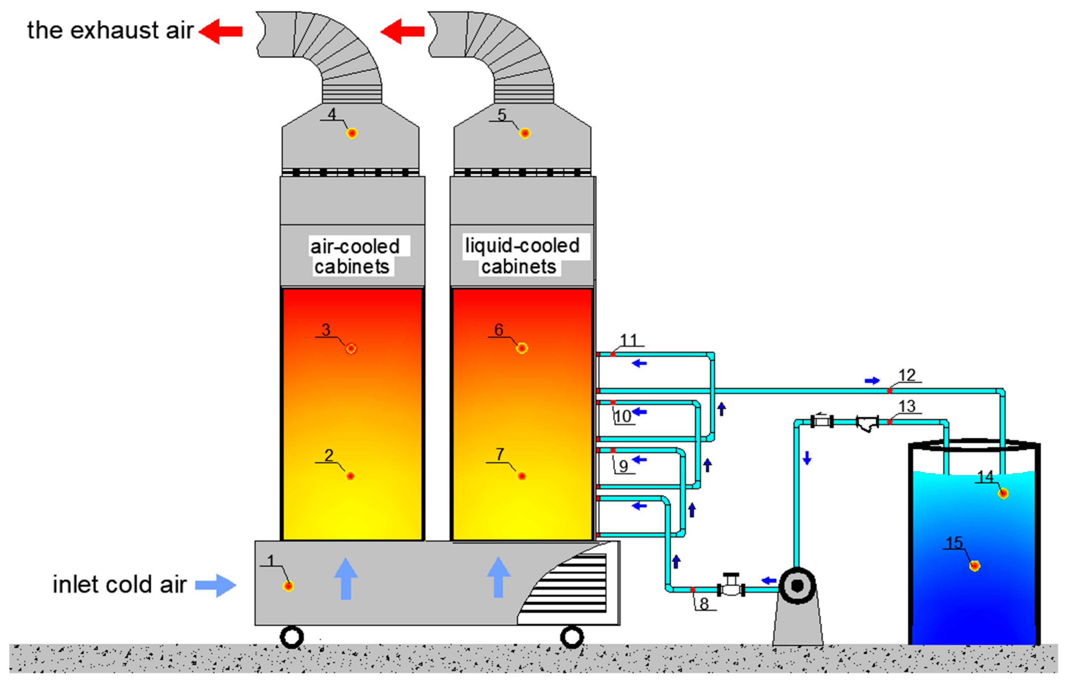
In view of the above-mentioned two thermal management strategies and various characteristics of three cooling technologies, it is also considered that oil cooling technology has been widely used in transformer cooling for a long time, and insulating oil is already ideal working fluid in liquid cooling technology. Under these conditions thereupon, in order to solve the heat dissipation problem of high heat density data center, this paper proposed a rear door oil-cooling heat exchanger device that could be applied to cabinet level cooling, and combined the thermal management strategy of cabinet level with oil cooling technology. More specifically, compared with the traditional CRAH system, the cabinet-level RDHE system of this paper was more targeted; it could effectively eliminate local hotspots in the data center, and avoided waste of cooling as much as possible. Likewise, compared with the water cooling system, the insulating cooling oil can effectively reduce the damage caused to the server due to the leakage of the working fluid and reduce the limitation of engineering application. Finally, the high-temperature cooling oil after cooling the cabinet could be utilized for the preparation of hot water, or regenerative desiccant and other uses to achieve waste heat recovery and reuse.

2. System Description

2.1. System Principle

The proposed system (Figure 1 and Figure 2) consisted of two parts, a communication cabinet system and a cooling system. Among them, the communication cabinet system comprised two cabinets, one was an air-cooled cabinet, and the other was a liquid-cooled cabinet. Both cabinets have a built-in analog heat source, which are used to simulate the heat dissipation of the real server. The working principle of the system could be summarized as the heat dissipation process of the communication cabinet. When the cabinet is operating, the simulated heat source starts to work and continues to generate heat. The air is responsible for all the heat of the air-cooled cabinet. The processing path is as follows: the cold air is sent into the communication cabinet through the downside air supply, and then the exchange heat with the heat source, which is eventually discharged by the top exhaust fan of the communication cabinet. The heat dissipation process of the liquid-cooled cabinet included the following two parts: one part of the heat was taken up by the cold air, and finally, by the top exhaust fan of the communication cabinet; another part of the heat was taken out of the cabinet by the RDHE system and finally stored in the heat storage oil drum.
The characteristics of the system could be explained in the following three aspects: (1) the liquid medium cooling oil used in the RDHE system has insulation property, does not cause any damage to electronic components and has no risk of liquid leakage, and is flexible in installation; (2) the system adopted a hybrid cooling method combining cooling oil and air cooling to improve the heat dissipation efficiency and energy utilization rate of the communication cabinet; (3) the heat dissipation system of the device belonged to the cabinet-level cooling. Different heat dissipation schemes could be implemented for cabinets with different heating densities.

2.2. Construction of the Testing Rig

2.2.1. Testing Rig

The communication cabinet system included a communication cabinet and a built-in analog heat source, which was used to simulate the heat dissipation of the real server. The heat dissipation system consisted of the RDHE system, the top exhaust unit and a movable downside air supply system. More specifically, the RDHE system was composed of a finned oil tube exchanger, an oil pump, an oil circuit system and a heat storage oil drum. The movable downside air supply system was connected to the communication cabinet to achieve the function of deliver cold air to the cabinet, and the operation of the whole system could be monitored in real time by the power detector.
In order to study the heat dissipation performance of the cabinet-level RDHE system, a novel testing rig was constructed in Guangdong University of Technology, China, as shown in Figure 3 and Figure 4. The test rig was mainly composed of three parts, namely the communication cabinet module, the heat dissipation system and the data acquisition system. The communication cabinet module consisted of two rack modules and a built-in analog heat source control system. The built-in analog heat source system included a voltage stabilizer, a voltage regulator and a PTC electric auxiliary heater. The heat dissipation system consisted of the RDHE system and an air-cooling system. Four finned oil tube exchanger, oil pump, heat storage oil drum and oil circuit system made up the RDHE system. The air-cooling system consisted of a movable downside air supply unit and a cabinet top exhaust unit. The data acquisition system included a multi-channel temperature and humidity monitor, a multi-channel temperature recorder and a power detector.
The two rack modules were made of 640 mm × 600 mm × 1050 mm traditional iron materials. In order to accurately calculate the heat dissipation capacity of the heat dissipation system, the surface of the rack was insulated with 20 mm thick insulation cotton, the outer door of the cabinet was made of 4 cm thick extruded board. The analog heat source system firstly regulated the circuit through the voltage stabilizer, and then adjusted the voltage regulator to control the PTC electric auxiliary heater to achieve different heating density conditions. The oil circuit system used a DN25 mm pipe for cooling oil delivery. In order to ensure the safe operation of the oil circuit system, the pipeline was equipped with a filter valve, a check valve, a flow valve and a turbine flow meter. The pipes connecting each oil-cooled radiator were transparent pipes, and the operation condition was checked regularly. The air-cooling system was coordinated by a movable downside air supply unit and a top exhaust unit of the cabinet, and the wind speed of the fan could be adjusted by a voltage regulator. Finally, the axial fan exhausted the hot air generated during the experiment through the galvanized pipe with a diameter of DN25. A multi-channel temperature recorder collected the temperature of the oil system, the temperature of the heat storage oil drum, and the internal temperature of the cabinet, and the temperature and relative humidity of the inlet air and the hot air of the cabinet were collected through a multi-channel temperature and humidity monitor. The performance parameters of main components were listed in Table 1.

2.2.2. Test Conditions

In view of the thermal guidelines for data processing environments [32], the equipment environment requirements for the data center were as follows: the dry bulb temperature was allowed to be 15–32 °C (recommended value is 18–27 °C) and the humidity range was allowed to be 20–80%, and no condensation is required. Moreover, based on experimental climatic conditions, the initial conditions of each set of experiments can be started within as small an error range as little as possible. Finally, we determined that the initial conditions of each test in this experiment started at a dry bulb temperature of 26 °C ± 1 °C and a humidity of 60% ± 10%.

2.2.3. Test Methods

The experimental test plan mainly included the arrangement of testing points, the testing procedures and the test data acquisition.
a. Arrangement of measuring points
The measurement parameters of this experiment mainly included the temperature and humidity of the inlet air of the cabinet, the temperature and humidity of the exhaust air of the cabinet, the temperature inside the communication cabinet, the cooling oil temperature of the oil system and the temperature of the heat storage oil drum. A total of 15 measuring points were arranged: three temperature and humidity measuring points and 12 temperature measuring points, all of which were arranged as shown in Figure 5. Among them, there were five measuring points in the communication cabinet system: measuring point 1, 4 and 5 were air temperature and humidity measuring points, measuring point 2, 3, 6 and 7 were air temperature measuring points; measuring point 8–15 were the temperature measurement point of the cooling oil.
b. The testing procedures
The test consisted of two parts, the comparison of the heat dissipation of the air-cooled cabinet and the liquid-cooled cabinet under the same working conditions, and the heat dissipation performance of the RDHE of the liquid-cooled cabinet under different working conditions. The initial test conditions of this experiment were started at a dry bulb temperature of 26 °C ± 1 °C and a humidity of 60% ± 10%. The PTC electric auxiliary heater was used to simulate the test conditions of different heating powers, and was set to 800 W and 1600 W. In this experiment, we measured the wind speed through a thermal anemometer. Since the different wind speeds of the fan match different fan powers, before the start of the experiment, the different powers of the fan were adjusted by the voltage regulator, and the wind speed of the fan was determined by the measurement with the thermal anemometer. Consequently, the average wind speed flowing through the surface of the heat exchanger was set to 3 m/s, 5 m/s and 7 m/s, respectively. The circulating oil flow was divided into large flow and small flow, which is 7.8 m3/h and 8.8 m3/h. Before the test, the quality of the oil drum was maintained at 170 kg. Then, the data acquisition system were opened, the test conditions debugged, and the test started immediately. The effective time of each test was 3 h. Specific test conditions are shown in Table 2 and Table 3.
c. The test data acquisition
The data acquisition system of this experiment performed data acquisition once every 1 minute. The main test method was direct measurement. However, there are factors such as long test time, more test instruments, more test conditions and inevitable errors between test points of the test instrument. In order to reduce the error caused by objective reasons, this experiment took the following measures during the test:
  • In order to reduce the error caused by the experimental external environment to the test platform, the experimental device was insulated with 20 mm thick insulation cotton, thereby ensuring the stability of the test parameters inside the experimental test platform.
  • In order to avoid random errors caused by measuring points, the method of averaging multiple points was used in the same position, to ensure the reliability of experimental test data.
  • In order to reduce the systematic error caused by the instrument itself, this experiment used a higher frequency test method to record the parameters of each test point of the experimental device under different working conditions on a time-by-time basis. In this experiment, the data acquisition time of the temperature tester and the temperature and humidity tester was set to 1 min during the test. At the same time, abnormal data could be clearly seen and removed in the data processing process, so that the experimental test data was more reliable.
  • In order to ensure the accuracy of the experimental data, during the experimental test, if abnormal data appears, the experiment need to be retested. When processing data, if there was data that occasionally floats large, it could be corrected according to the change rule of the data before and after.

3. Methodology

In this section, the analysis of the heat dissipation performance of this system in two ways is described. Firstly, from the perspective of theoretical analysis, the parameters such as cumulative heat dissipation, average heat dissipation efficiency and coefficient of performance were analyzed. Following this, based on this system, an energy balance model was established to further analyze and verify the heat dissipation performance of the system.

3.1. Theoretical Analysis

In order to characterize the heat dissipation performance of this system, the cumulative heat dissipation, the average heat dissipation efficiency and the coefficient of performance will be analyzed.
There are two types of heat dissipation media for the cabinet, namely oil and air. The validity of the heat transfer of the two media can be calculated using Equations (1) and (2), respectively. The cumulative heat dissipation of the RDHE was calculated by Equation (1):
Q o i l = m o i l × c p , o i l × Δ t o i l ,
The cumulative heat dissipation of the fan was defined according to Equation (2):
Q a i r = c p , a i r × Δ t a i r × ρ a i r × A a c × v × τ ,
Regarding the heat generation of the cabinet, this experiment used a simulated heat source heater for simulation, and monitored the operating power of the simulated heat source for statistics Equation (3) was given in the following calculation:
Q T = P s × τ × 60 ,
In addition, when the system was running, the transportation process of the fan and the oil pump will generate a certain amount of heat. The specific numerical statistics were calculated according to Equations (4) and (5):
Q f a n = P f a n × τ × 60 ,
Q p u m p = P p u m p × τ × 60 ,
Next, the average heat dissipation efficiency of the RDHE will be calculated, and the average heat dissipation efficiency could directly reflect the heat dissipation of the device. The average heat dissipation efficiency was calculated according to Equation (6):
η = Q d Q T × 100 % ,
With the exception of the average heat dissipation efficiency, the coefficient of performance (COP) could also directly reflect the energy efficiency conversion of the entire system, which was an important evaluation index. The coefficient of performance (COP) could be calculated by Equation (7):
C O P = Q o i l + Q a i r ( P p u m p + P f a n ) × τ × 60 ,

3.2. The Energy Balance Model

There were three basic ways of transferring heat: heat conduction, heat convection, and heat radiation. According to the heat dissipation process of the cabinet (Figure 6), the energy balance of this system initially could be expressed with Equation (8):
Q ˙ h e a t   p r o d u c e = Q ˙ c o n v 1 + Q ˙ c o n v 2 + Q ˙ c o n n d + Q ˙ r a d ,
where Q ˙ h e a t   p r o d u c e is the source of heat, Q ˙ c o n v is the heat loss by convection from heat surface to the air, Q ˙ r a d is the heat loss by long-wave radiation exchange from the heat source to the walls and Q ˙ c o n d is the heat loss by conduction through the wall surfaces to the surroundings.
Among them, as can be seen from Figure 6, since the system has adopted better insulation measures outside the cabinet, the outer surface of the cabinet was insulated with 20 mm thick insulation cotton, and the outer door of the cabinet was made of 4 cm thick extruded board. Therefore, the heat flow from the cabinet to the outside through heat conduction was generally considered to be small enough to be negligible ( Q ˙ c o n d ≌ 0).
The heat produced by the cabinet was equal to the heat generated by the PTC analog heat source built into the cabinet. It could be calculated as follows:
Q ˙ h e a t   p r o d u c e = P ,
During this experiment, the convection heat transfer consisted of two parts. The first part was that the hot air inside the cabinet transfers heat to the RDHE through heat convection, this part was named Q ˙ c o n v 1 . The other part was that hot air transfer heat to the inner wall of the cabinet through heat convection, this part was named Q ˙ c o n v 2 . These two parts of heat could be calculated by the following formula:
Q ˙ c o n v 1 = h a × A h t 1 × ( t w , R D H E t f ) ,
Q ˙ c o n v 2 = h a × A h t 2 × ( t w , c a b i n e t t f ) ,
The heat transfer from the heat source to the inner wall of the cabinet by long-wave radiation could be calculated on the basis of the Stefan-Boltzmann’s law. In this special case, the default cabinet was completely enclosed. Therefore, the amount of heat radiation by long-wave radiation was expressed by Equation (12):
Q ˙ r a d = ε × σ × A r a d × ( t s u r 4 t a i r 4 ) ,

4. Analysis and Discussion of the Testing Results

In this part, preliminary experiments were conducted on the heat dissipation performance test of the air-cooled cabinet and the liquid-cooled cabinet, and the experimental results were analyzed and discussed. Furthermore, the heat dissipation performance of the RDHE of the liquid-cooled cabinet was studied. Based on the test results, the heat dissipation performance of the RDHE will be analyzed from four evaluation indicators for the system operating under different working conditions, namely the average heat dissipation efficiency, the cumulative heat dissipation, energy saving potential and the coefficient of thermal performance.

4.1. Comparison between Traditional Air-Cooled Cabinets and Liquid-Cooled Cabinets

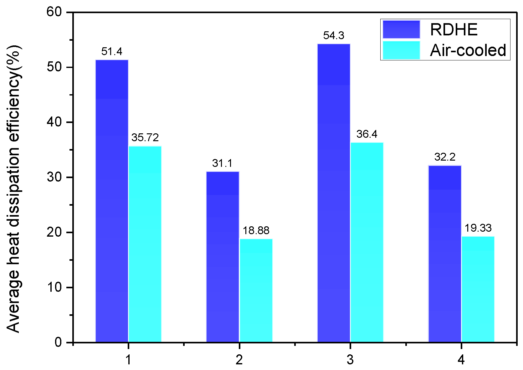
This section compared the heat dissipation of traditional air-cooled cabinets with liquid-cooled cabinets. Taking the working conditions 1–4 as an example, the test was divided into four groups, and the heat dissipation of the two cabinets was analyzed from the average heat dissipation efficiency, the cumulative heat dissipation and the operating temperature of the cabinet. It could be seen from Figure 7 that, under the same working conditions, the average heat dissipation efficiency of the RDHE in the liquid-cooled cabinet was higher than that of the air-cooled cabinet Among them, compared with the traditional air-cooled cabinet, under the same heat source power, the average heat dissipation efficiency of RDHE could be increased by up to 66.6%. The statistics of the cumulative heat dissipation of the two cabinets are shown in Table 4; the cumulative heat dissipation of the liquid-cooled cabinet was much higher than that of the air-cooled cabinet. In addition, this section also compared the operating temperatures of the two cabinets. It can be seen in Table 5 that the operating temperature of the cabinet of the traditional air-cooled cabinet was higher than the temperature of the liquid-cooled cabinet, and the operating temperature of the liquid-cooled cabinet did not exceed 50.5 °C. There was no doubt that the heat dissipation capability of the liquid-cooled cabinet was much higher than that of the air-cooled cabinet, and the communication cabinet could be maintained stably and safely.
Although the liquid cooling system had the above benefits over other air-cooled base systems, the main disadvantage was to ensure liquid sealing and thus avoid leakage problems. The system was a rear door liquid-cooled cabinet, compared with the general liquid-cooled cabinet, the leakage of electronic components was reduced as much as possible, but there were still hidden dangers and the system needs to be sealed.

4.2. Average Heat Dissipation Efficiency of the RDHE

The average heat dissipation efficiency is the ratio of the cumulative heat dissipation to the total heat generation of the simulated heat source during the experimental test conditions. It is one of the main indicators reflecting the heat dissipation performance of the heat dissipation device of the communication cabinet.
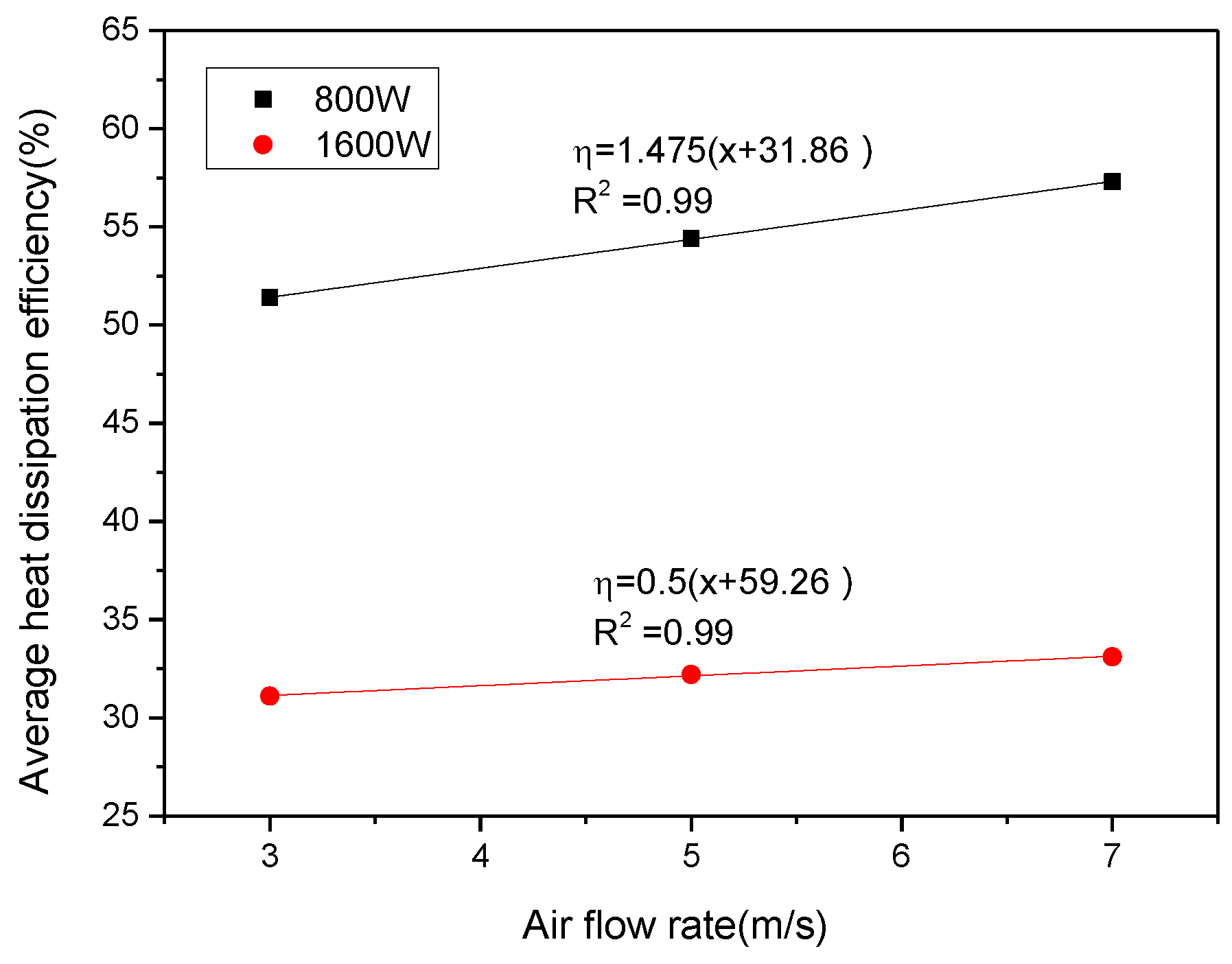
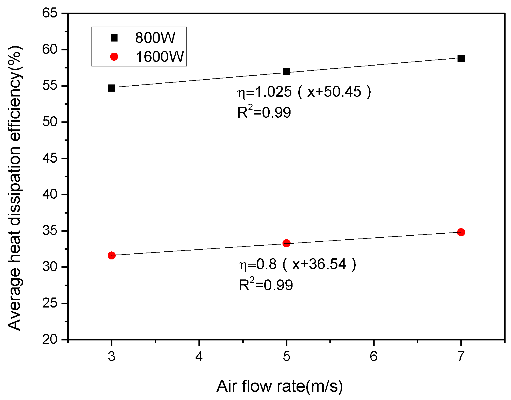
The average heat dissipation efficiency is one of the main indicators reflecting the heat dissipation performance of the RDHE. Under the same test conditions, the larger average heat dissipation efficiency means greater heat dissipation capability. The average heat dissipation efficiency of the RDHE was tested by changing the cooling oil flow rate and the fan wind speed under the same simulated heat source power, as shown in Table 6. When the simulated heat source power in the range of 800–1600 W, the average heat dissipation efficiency of the heat dissipation performance of the RDHE was 44.1%. The RDHE has a larger heat dissipation capacity when the heat source power is 800 W, and the average heat dissipation efficiency could reach 58.8%.
According to the test results, it could be concluded that under the same cooling oil flow rate, the average heat dissipation efficiency of the RDHE under the influence of different wind speeds showed a linear growth trend with the increase of wind speed, as shown in Figure 8 and Figure 9. It showed that the RDHE has better heat dissipation effect in the case of good airflow organization.

4.3. The Cumulative Heat Dissipation

The cumulative heat dissipation of the RDHE was mainly calculated by the temperature rise of the oil in the heat storage oil drum, and the cumulative heat dissipation of the device was calculated according to Equation (1). 
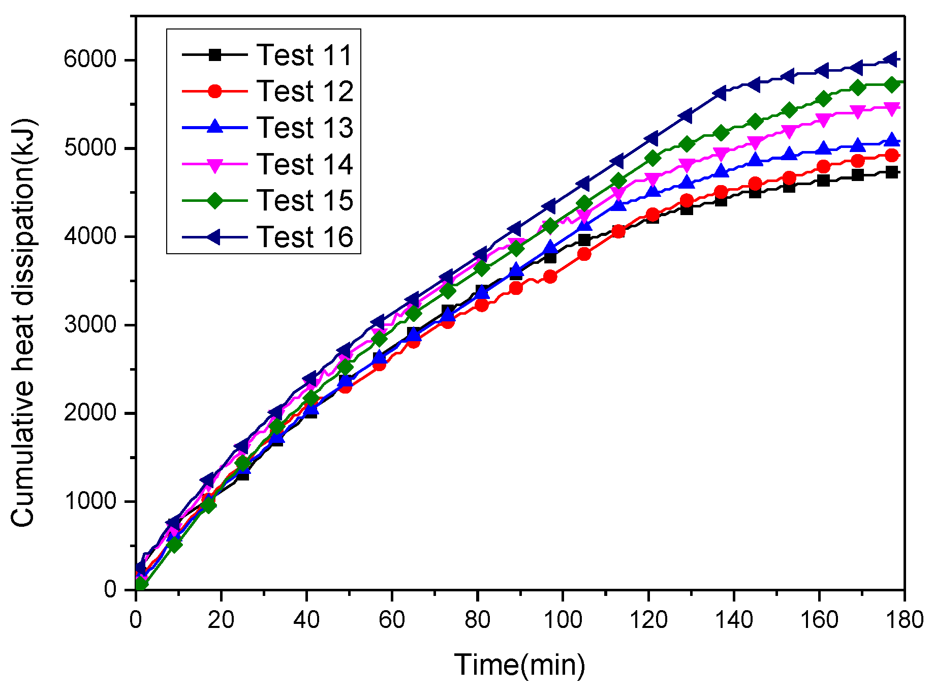
Table 7 showed the cumulative heat dissipation of the heat storage oil drum under different working conditions. When the simulated heat source power in the range of 800–1600 W, the average cumulative heat dissipation of the RDHE could reach 5226 kJ, and when the heat source power was 1600 W, the maximum could reach 6009 kJ.

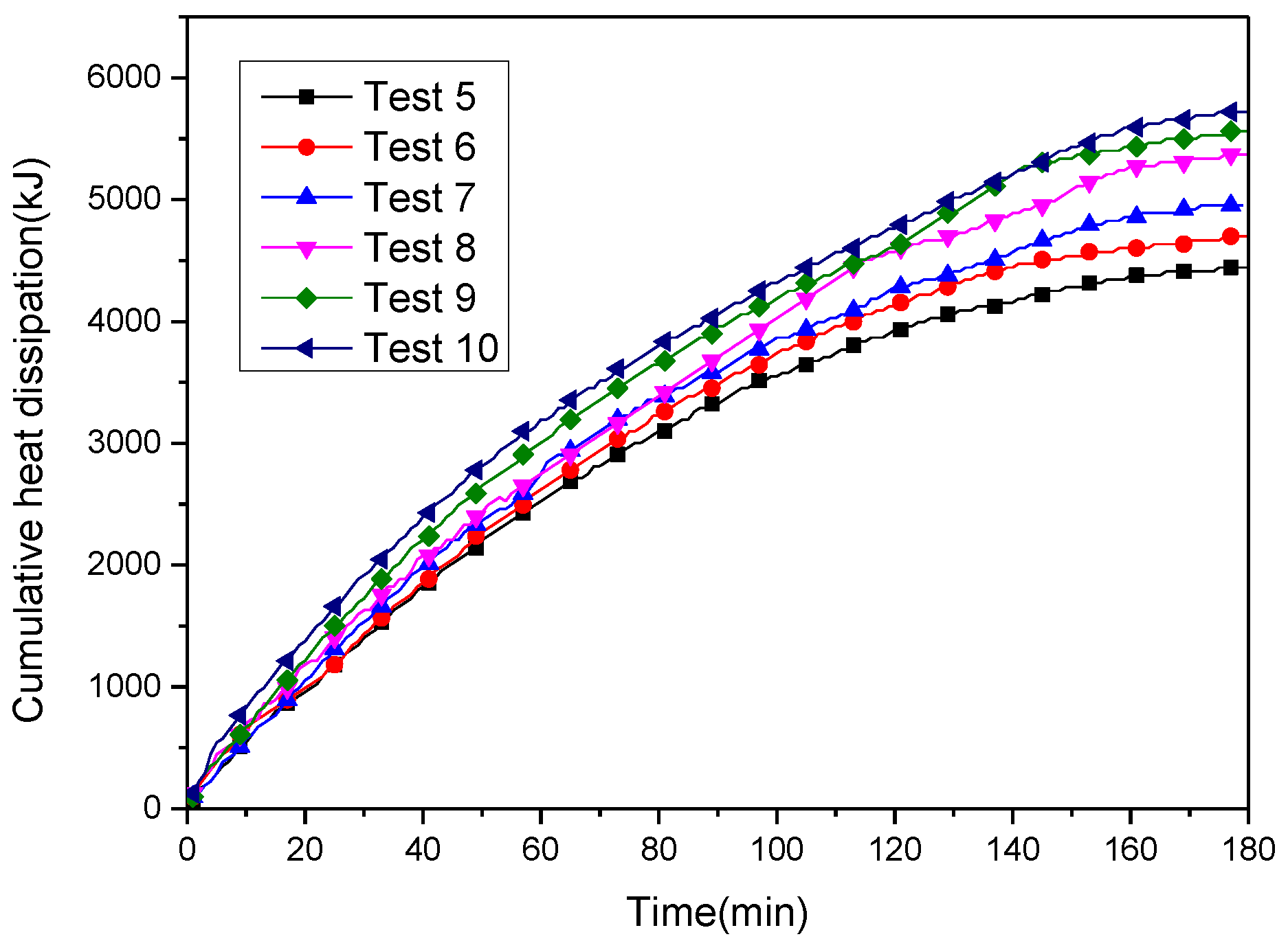
4.3.1. The Trend of Heat Dissipation

The entire experimental test time was 3 h. In order to study the trend of heat dissipation of the RDHE with time, the experimental results of the test 5–16 were taken as an example. It can be seen in Figure 10 and Figure 11 that in the early stage of the test, the heat dissipation rate of the RDHE increased rapidly, and the growth gradually became flat during the test period, and finally the heat dissipation amount tended to be stable. Choi et al. [33] pointed out that the operating temperature of the CPU is generally lower than 70 °C. Bar-Cohen [34] found that when the CPU operating temperature exceeded the allowable operating temperature, the reliability of the chip was reduced by 10% for every 2 °C. Through the data acquisition system, it was found that the final temperature in the cabinet is as shown in Table 8 after three hours of operation. Under the heat dissipation work of the RDHE, the temperature of the cabinet could be lower than 70 °C, and the maximum was 50.9 °C, which indicated that the heat dissipation of the RDHE is more effective and can maintain good operation inside the cabinet.

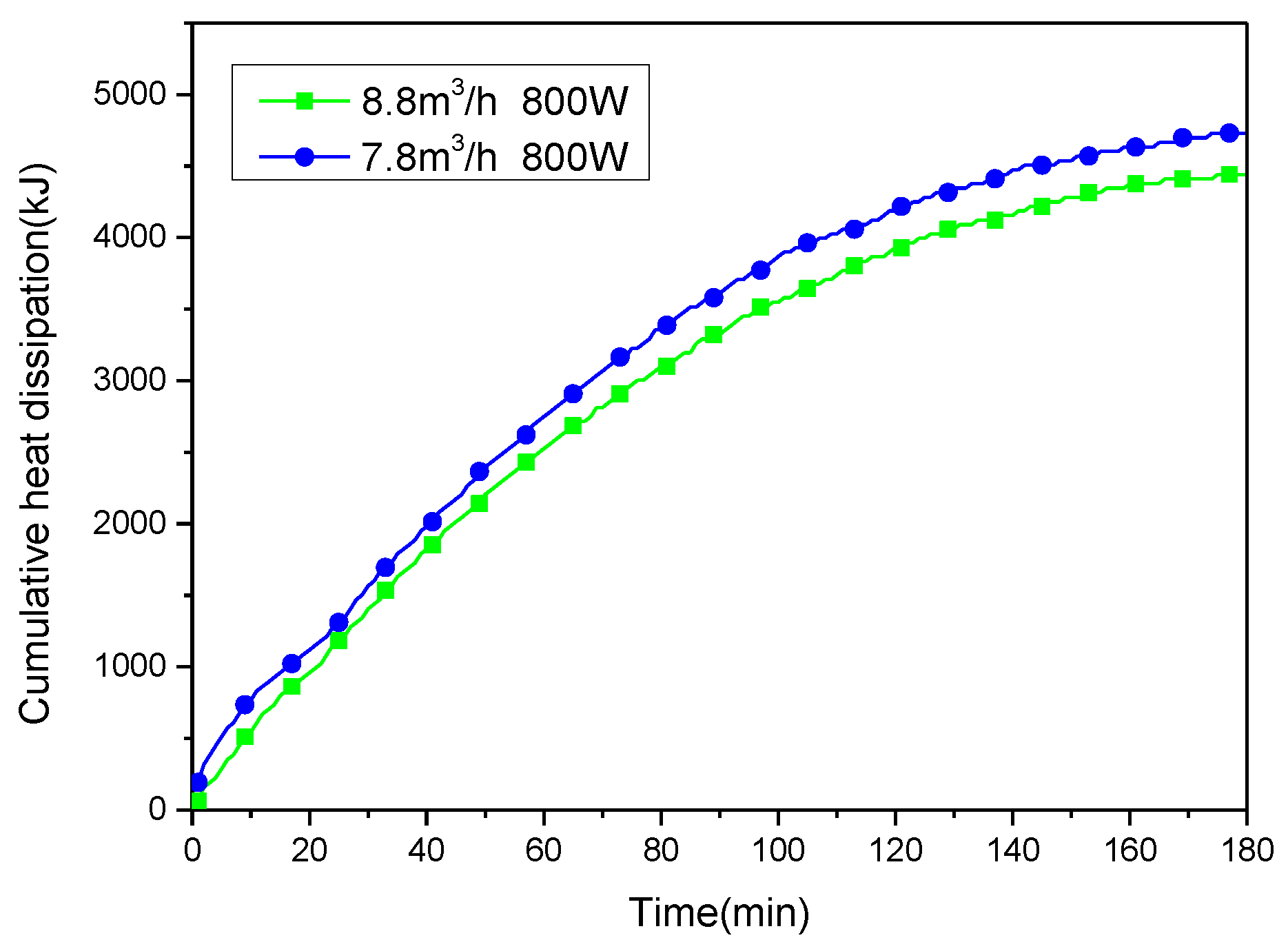
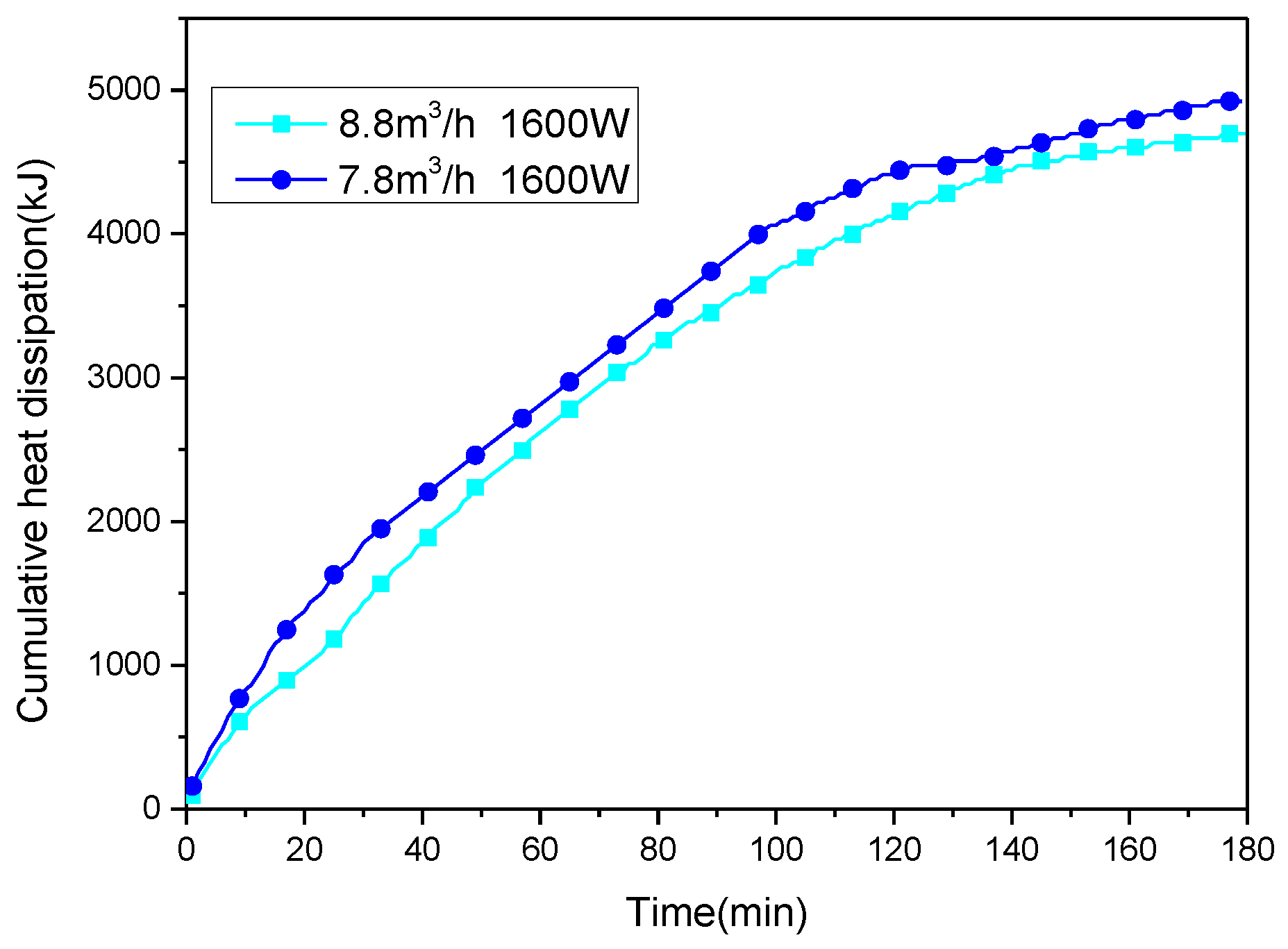
4.3.2. Cooling Oil Flow

In order to explore the heat dissipation of the RDHE compared the heat dissipation of the system under different flow rates. In this experiment, two flow rates were set, 7.8 m3/h and 8.8 m3/h. In the case of the same heat source power and the same air flow rate, a comparative test was carried out. In the case of the condition of 800 W heat source power, the experimental results of tests 1 and 7 were taken as an example. In the case of the heat source power of 1600 W, the experimental results of tests 4 and 10 were taken as an example for analysis. The experimental results are shown in Figure 12 and Figure 13. It can be seen from Figure 8 that the RDHE has better heat dissipation capability and could carry away higher heat when operating at a small flow rate of 7.8 m3/h. Due to the reduced flow rate, the cooling oil could be better exchanged in the cabinet. Through comparative analysis, it could find when the cooling oil is operated at a flow rate of 7.7 m3/h, the heat dissipation capacity can be increased by 6%.

4.4. Potential Heat Recovery Characterization

Based on the rapid development of data centers and the large amount of heat in the data center, waste heat recovery has become an important research direction. Regarding the waste heat recovery in data centers, Ebrahimi et al. [1] proposed several directions that could be applied to waste heat utilization in data centers, including the following uses: (a) domestic space and water heating; (b) power plant co-location; (c) absorption cooling; (d) organic Rankine cycle; (e) desalination; (f) biomass processing; (g) piezoelectrics; (h) thermoelectrics.
The allowable temperatures for waste heat recovery in different cooling systems varied from a higher range of 50–60 °C and a lower range of 25–35 °C [34]. Through experimental tests, it was found that the circulating cooling oil of this experiment and the exhaust at the top of the cabinet has a certain heat recovery value.

4.4.1. The Temperature of Cooling Oil

Due to the uncontrollable ambient temperature, there were small variations in the ambient temperature and humidity of each set of experiments and the initial temperature of the heat storage oil drum, but the initial conditions of each test in this experiment started at a dry bulb temperature of 26 °C ± 1 °C and a humidity of 60% ± 10%. The initial temperature of the oil was 28.5 ± 0.5 °C. The quality of the oil in the heat storage oil drum was always 170 kg before each test. Table 9 showed the temperature changes of the heat storage oil drum during the experimental test under the different working conditions. Under the different working conditions, the final temperature of the heat storage oil drum could be higher than 42.8 °C, and the highest temperature could reach 46.9 °C. In the London district heating network program, for secondary heat sources, heat from the data center at temperatures ranging from 32–40 °C was considered to be the most cost-effective and carbon-efficient heat source [1]. It could be seen that the cooling oil becomes high-temperature oil after the experiment, and could be used as a heat source at this time to prepare domestic water, which can improve energy utilization and achieve the purpose of utilizing waste heat of the data center. After the heat recovery is fully realized, the high temperature oil is returned to the low temperature oil and the data room is continuously re-cooled.

4.4.2. The Temperature of the Exhaust Air of the Cabinet

When the liquid cooling device performed heat dissipation, the top exhaust unit of the cabinet also performed the heat dissipation work at the same time. Under the test of different heat source power, by adjusting the wind speed of different fans, it was found that the exhaust air temperature of the cabinet also had a certain utilization value. Table 10 shows the variation of exhaust air temperature during the experimental test under the different working conditions. It can be found that under the same oil flow rate and the same heat source power, the larger the air flow rate, the greater the temperature rise of the exhaust air. In the case of different working conditions, the final temperature of the exhaust air could be higher than 40 °C, and the highest could reach 42.8 °C. The temperature range of the captured waste heat from air cooled servers (35–45 °C) is more than sufficient for reuse in heating needs [35]. The high temperature exhaust air temperature embodies two aspects. On the one hand, it effectively maintains the temperature stability inside the cabinet and contributed to work normally. On the other hand, the high-temperature exhaust air temperature could have sufficient heat recovery value, and could be used as a heat source to regenerate the desiccant, and to improve energy utilization. After the heat exchange, the high temperature air could re-enter into the machine room for cooling work to achieve the purpose of rational use of resources.

4.5. The Coefficient of Thermal Performance

The coefficient of thermal performance (COP) is the ratio of the heat dissipation of the heat sink to the input shaft power under the test conditions. It is another important indicator of the heat dissipation performance of the reaction liquid cold cabinet test system. It can also reflect the energy conversion rate of the device.
The coefficient of performance (COP) calculation results are shown in Table 11 below. It can be seen that with the increase of wind speed and cooling oil flow, COP showed an increasing trend, indicating that in a good airflow organization environment, the heat dissipation environment in the cabinet is good, and the heat dissipation performance of RDHE is more effective. At different flow rates, smaller flows also exhibited better heat dissipation. In general, the average COP of the entire system could reach 0.85, indicating that the system has good heat dissipation performance.

4.6. The Discussion of the Model

In order to further illustrate the heat dissipation performance of this model, this part verified the experimental results and the energy balance calculation model. In addition, based on the experimental results, a calculation model was established to predict the increase trend in heat dissipation of RDHE with the test time.

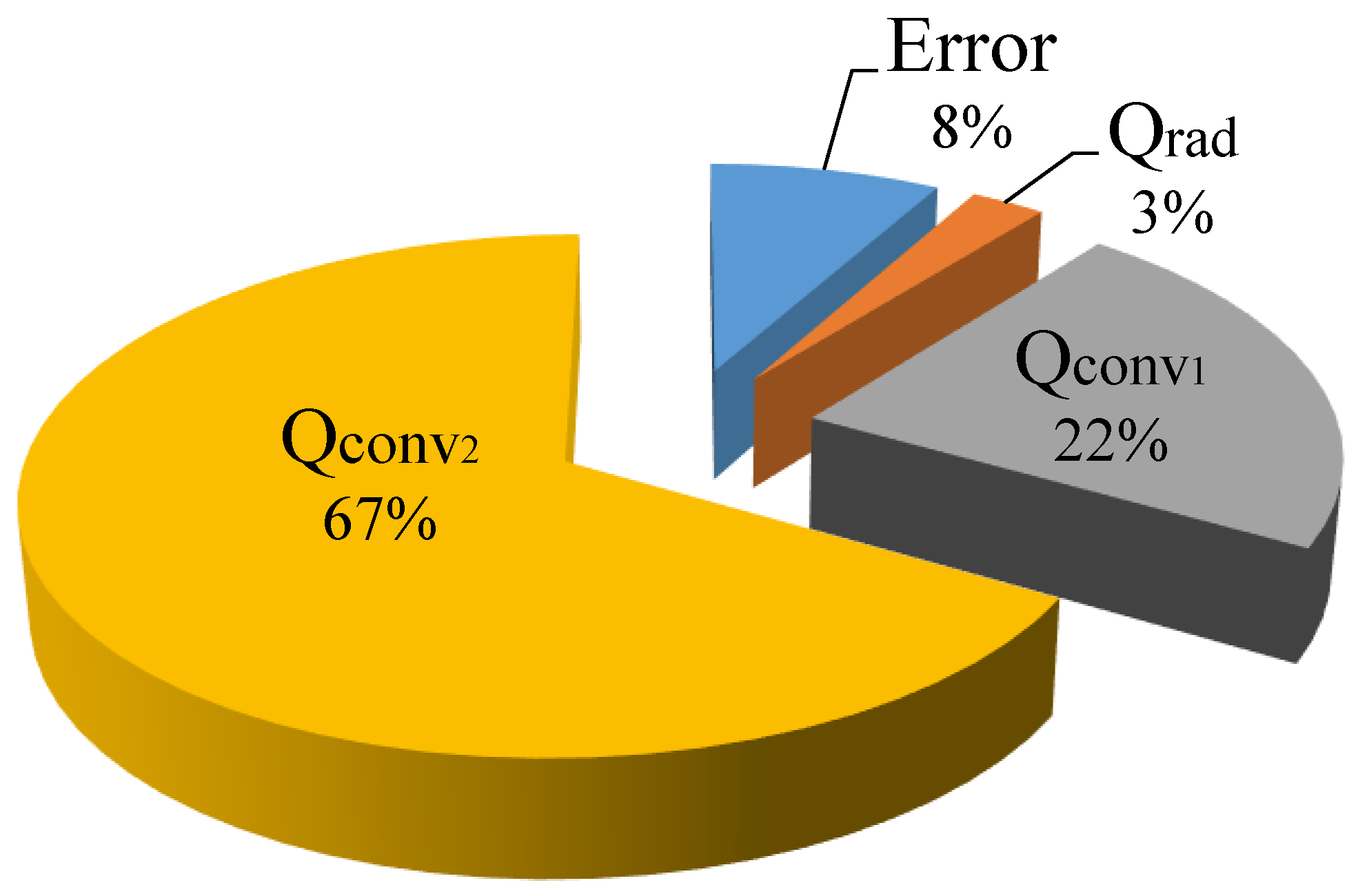
4.6.1. The Verification of the Energy Balance Model

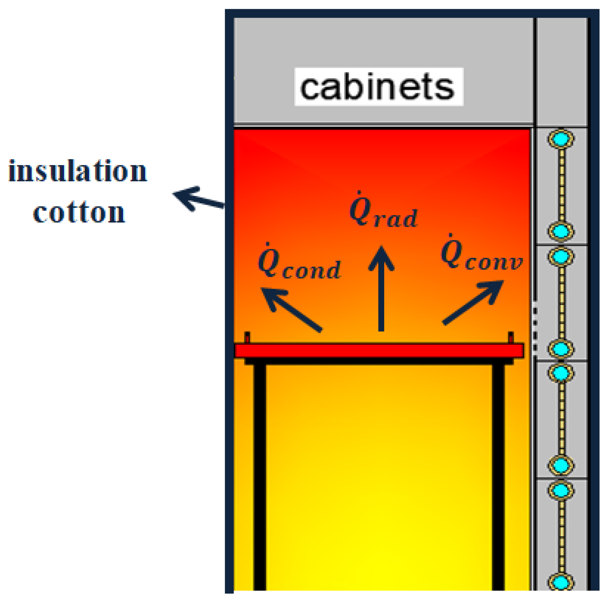
This part verified the experimental results and the energy balance calculation model. After verification, it was found that the system and the energy balance model can be well matched with an error of 8%. Thus, this energy balance model could be applied to the heat calculation of this system. The distribution of heat in the energy balance is shown in the Figure 14 below.

4.6.2. The RDHE Calculation Model

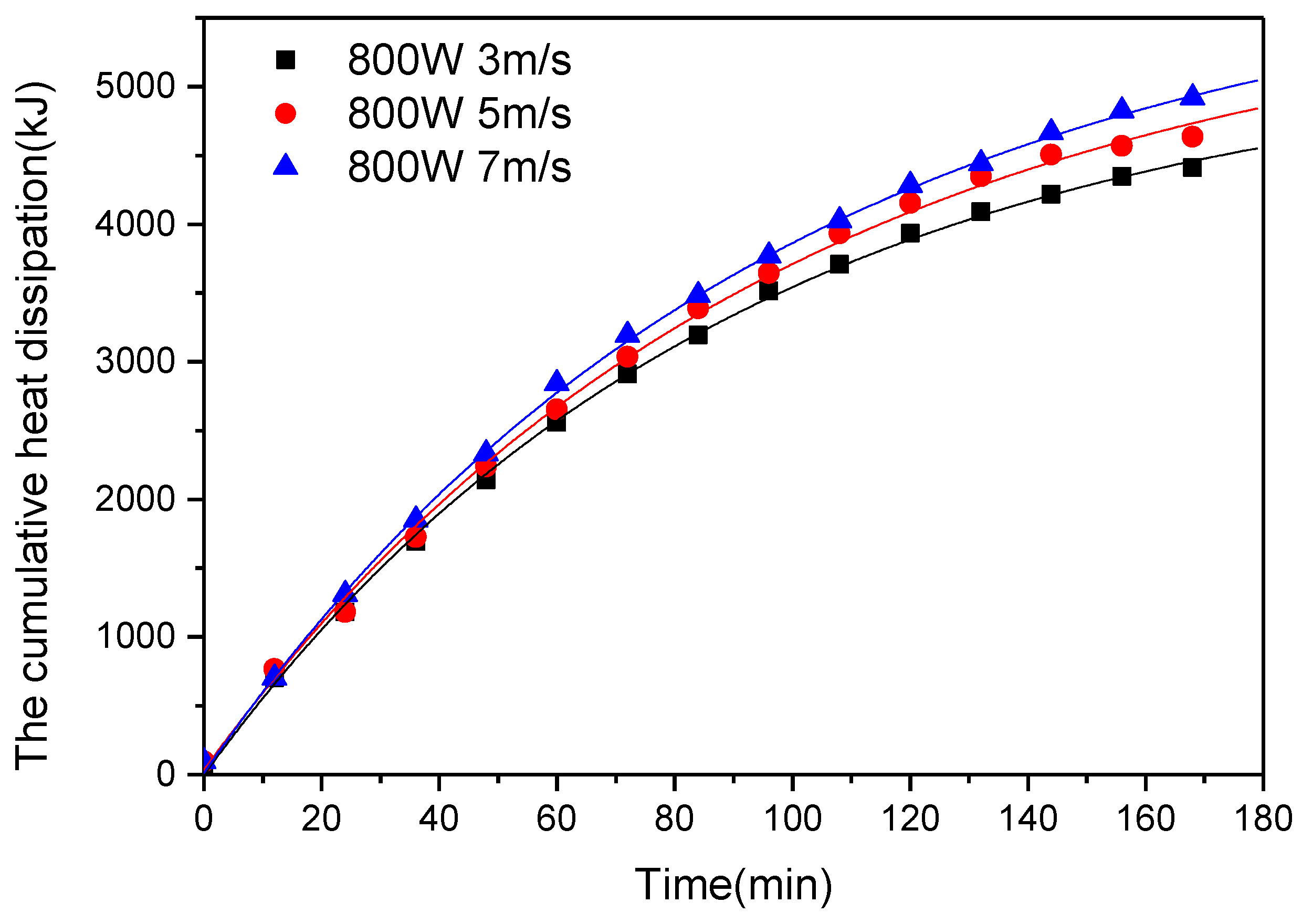
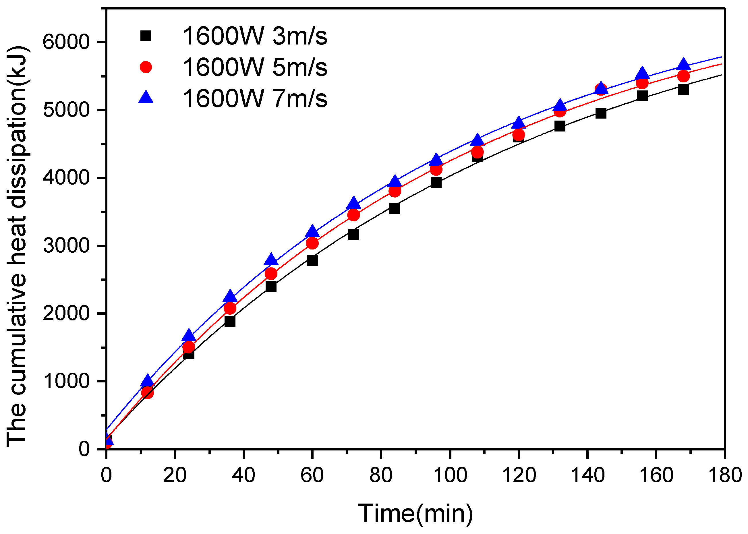
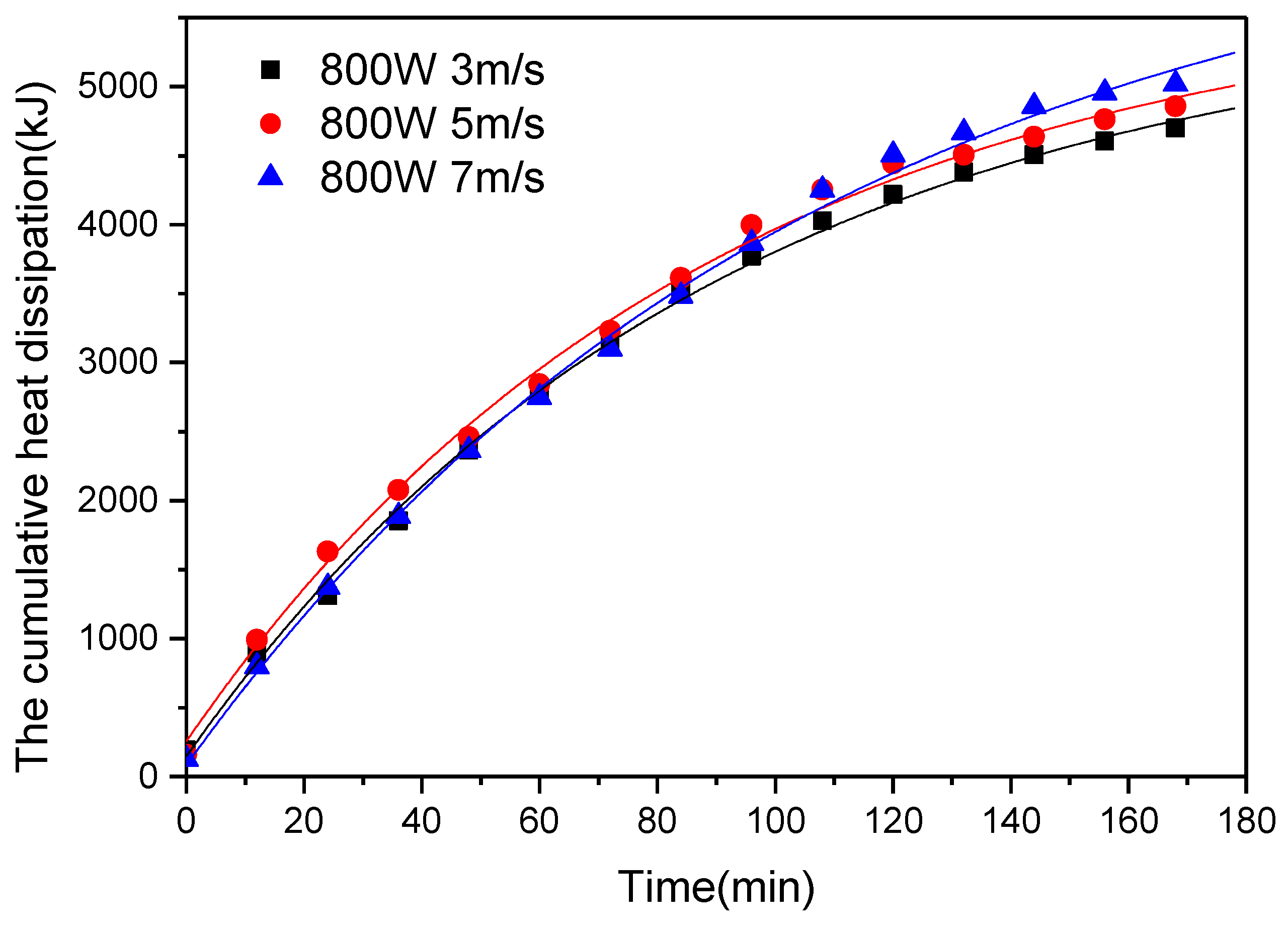
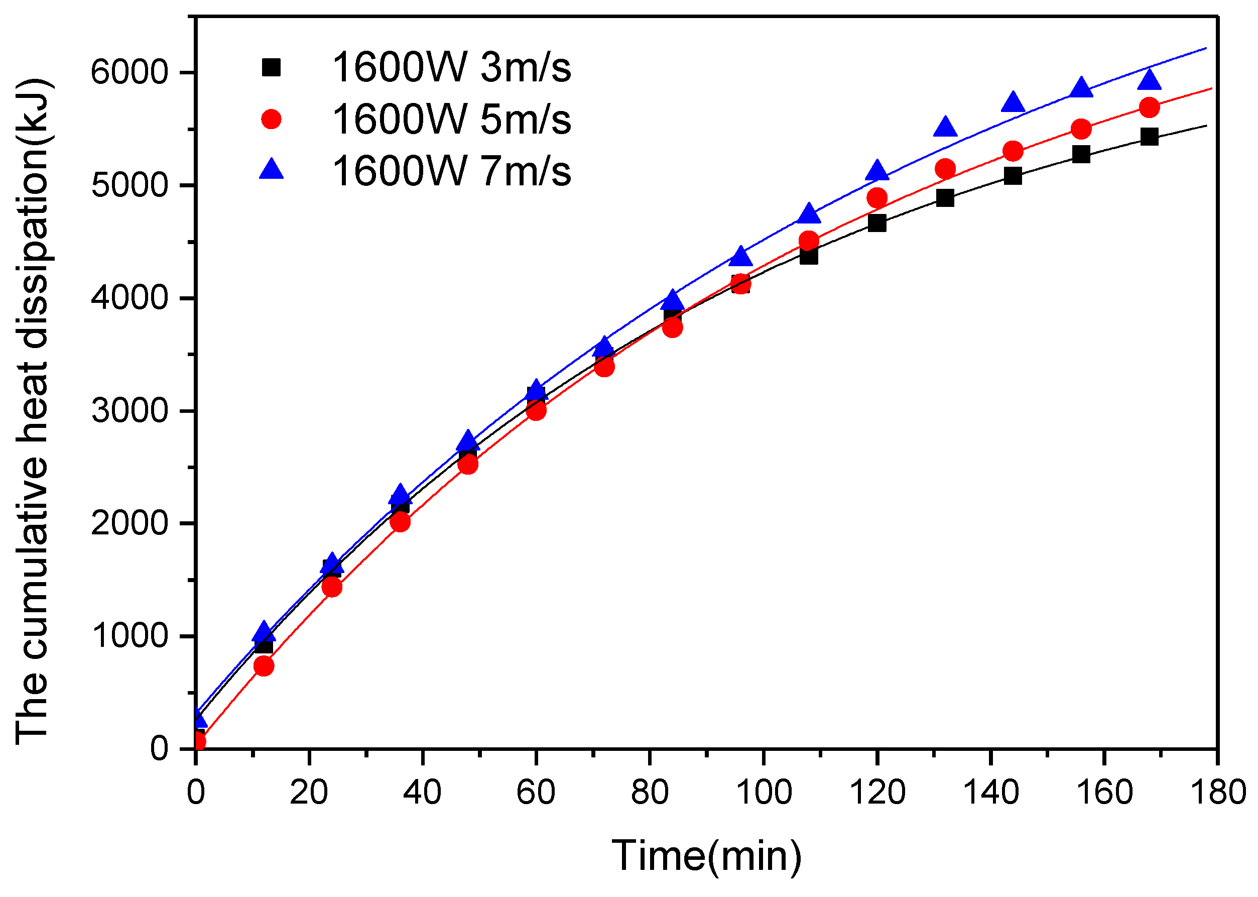
Based on the experimental results, a calculation model was established to predict the increase trend in heat dissipation of RDHE with the test time. The study found that the cumulative heat dissipation of the RDHE cooling device was a logarithmic change. Based on the experimental test data, we could assume that the logarithmic model equation is as follows:
Q o i l = Q Q × exp ( τ B ) ,
The coefficients and regression formula correlation are gained by the test results and shown in Table 12.
Comparing the test results with the calculating value by the calculation model, the calculation model can perform well in predicting the increase trend in heat dissipation of RDHE with the test time under different test conditions. The comparison of the test results with the model calculating value are show from Figure 15, Figure 16, Figure 17 and Figure 18 under different conditions.

5. Conclusions

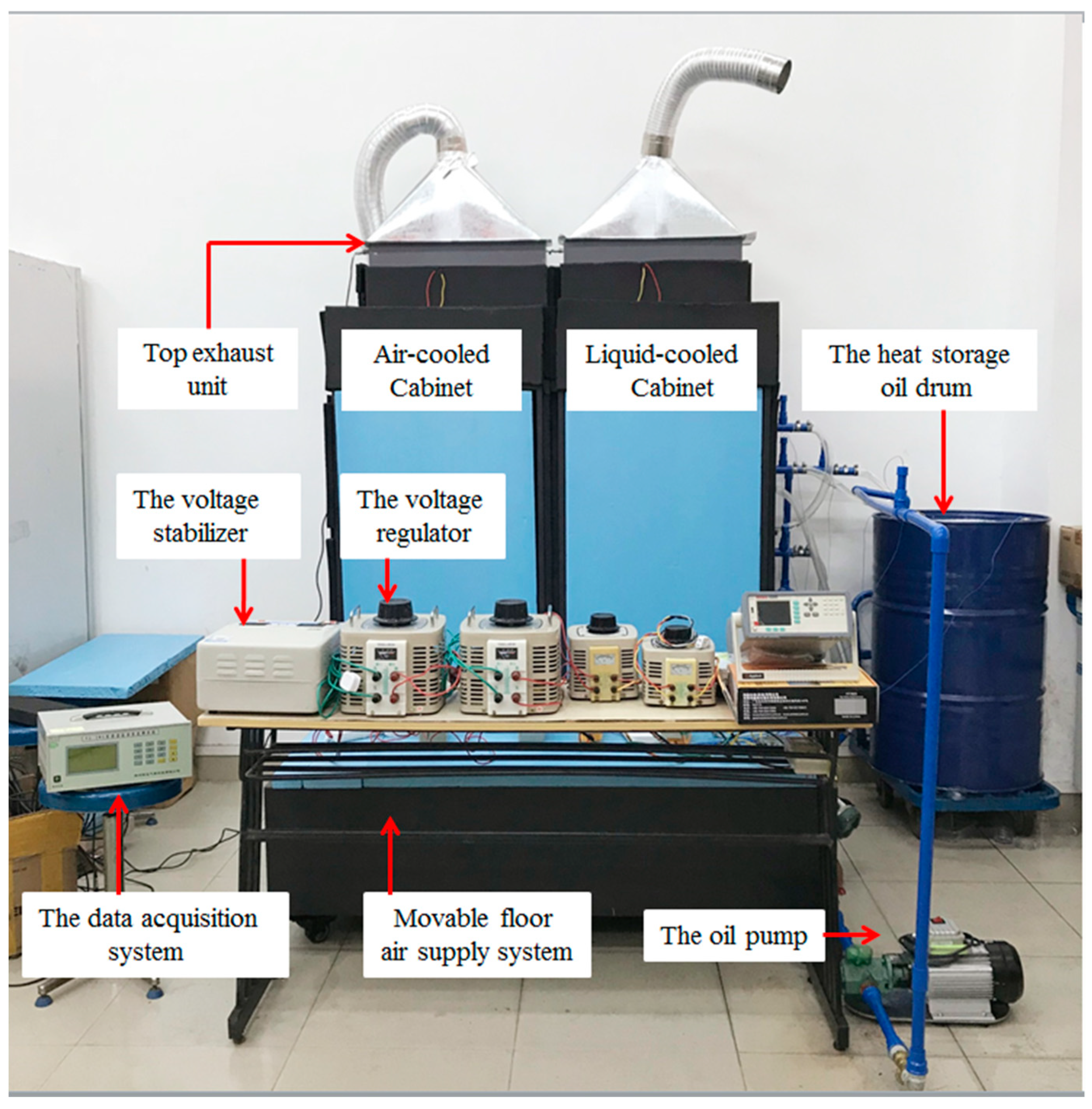
This paper proposed a novel rear door oil-cooling heat exchanger device for cabinet-level cooling. The heat dissipation performance of the RDHE was tested experimentally and compared with the heat dissipation performance of the conventional air-cooled cabinet. In order to explore the heat dissipation performance of the RDHE, the test rig was constructed and tested in the laboratory of Guangdong University of Technology under different simulated heat source conditions and cooling oil flow conditions. The parameters used to evaluate the performance of the RDHE, namely the average heat dissipation efficiency, the cumulative heat dissipation, the potential heat recovery characterization and the coefficient of thermal performance. Moreover, a calculation model based on energy balance was established and the accuracy of the experiment was verified. Furthermore, according to the variation law of the cumulative heat dissipation of the RDHE, the regression fitting could be used to predict the heat dissipation law. It was found that:
  • Compared with the traditional air-cooled cabinet, the RDHE’s heat dissipation capacity has increased by an average of 56.2%, and the maximum can be increased by 66.6%.
  • When the simulated heat source power is in the range of 800–1600 W, the average heat dissipation efficiency of the heat dissipation performance of the RDHE was 44.1%. When the cooling oil flow rate was 7.8 m3/h, the wind speed was 7 m/s and the RDHE was operated at a heat source of 800 W, the heat dissipation efficiency was up to 58.8%.
  • After running for three hours, under the cooling work of the RDHE, the cabinet temperature under different working conditions could be lower than 70 °C (this temperature was the specified allowable operating temperature of the cabinet). The experimental results showed that the maximum temperature of the cabinet temperature in all tests was only 50.9 °C, which indicated that the heat dissipation of the RDHE is more effective and can maintain good internal operation of the cabinet.
  • Both the circulating cooling oil of this experiment and the exhaust unit of the cabinet have potential heat recovery values. Among them, the final temperature of the oil drum could be higher than 42.8 °C; the highest could reach 46.9 °C. The final temperature of the exhaust air could be higher than 40 °C; the highest could reach 42.8 °C. After heat reuse, the temperature of the circulating oil could be lowered, and the next cooling could be performed better.
  • With the increase of wind speed and cooling oil flow, COP showed an increasing trend, indicated that in a good airflow organization environment, the heat dissipation environment in the cabinet is good and the heat dissipation performance of RDHE is more effective. At different flow rates, smaller flows exhibited better heat dissipation. In general, the average COP of the entire system could reach 0.85, which indicated that the system has good heat dissipation performance.
  • After calculation, the system and the established energy balance calculation model could be well matched with an error of 8.1%. According to the logarithmic variation law of the cumulative heat dissipation of the RDHE, the regression fitting was carried out. It was found that under different experimental conditions, the model could predict the heat dissipation law of the RDHE well and have a good agreement with the experimental values.
The study demonstrated that, compared with the traditional air-cooled cabinet, the RDHE could exhibit better heat dissipation and has a potential heat recovery value. The system is suitable for applying in high heat density data room, and it could be used in areas with district heating networks to achieve waste heat utilization in data centers. Typically, in practical applications, both liquid-cooled and air-cooled data centers would have completely different designs and hardware configurations, and it may be difficult to use them directly in practice. Although the liquid cooling system has the above advantages over other air-cooled base systems, the main disadvantage is to ensure liquid sealing and thus avoid leakage problems. In most liquid-cooled designs, coolant pumps are required for delivery. To ensure the safety of personnel and equipment, leak detection systems are required for practical applications. The system is a rear door liquid-cooled cabinet; compared with the general liquid-cooled cabinet, the system does not directly touch the electronic components inside the cabinet, the leakage of electronic components is reduced as much as possible, but there were still hidden dangers and the system needs to be sealed. The next step of this study is to study the thermal performance of the entire system, the economic benefits of heat recovery and the optimization of the experimental equipment, providing an effective theoretical basis for the use of the system in practical applications.

Author Contributions

W.Y. conceived and designed the study; L.Y. and J.O. performed the experiments; L.Y. and Z.L. analyzed the data; L.Y. wrote the paper; X.Z. contributed analysis tools.

Funding

This work was financially supported by the National Key R&D Program of China (2016YFE0133300), the European Commission H2020-MSCA-RISE-2016 Program (734340-DEW-COOL-4-CDC), and the European Commission H2020-MSCA-IF-2018 Program (835778-LHP-C-H-PLATE-4-DC).

Conflicts of Interest

The authors declare no conflict of interest.

Nomenclature

ITinformation technology;
PUEpower usage effectiveness;
CFDcomputational fluid dynamics
PTCpositive temperature coefficient
CPUcentral processing unit
CRAHcomputer room air handlers;
RDHErear door heat exchanger;
NFnanofluid
η the average heat dissipation efficiency (%);
COP the coefficient of thermal performance;
Q d the accumulated heat dissipation (kJ);
Q T the total heat generation of the simulated heat source (kJ);
Q o i l the accumulated heat dissipation of RDHE (kJ);
Q a i r the accumulated heat dissipation of air (kJ);
Q p u m p the heat generation of the oil pump (kJ);
Q f a n the heat generation of the fan (kJ);
Q ˙ h e a t   p r o d u c e the source of heat (W);
Q ˙ c o n v the heat generated by heat convection from the object (W);
Q ˙ c o n d the heat generated by heat conduction from the object (W);
Q ˙ r a d the heat generated by thermal radiation from the object (W);
Q the accumulated heat dissipation after stabilization;
P power (W);
τ time (min);
m mass (kg);
c p specific heat (J/(kg∙K));
h a the convective heat transfer coefficient of air (W/( m2∙K));
t temperature (K);
A area (m2);
v air flow rate (m/s);

Subscripts

pumppump;
fanfan;
oiloil;
airair;
dheat dissipation;
Tthe total heat generation;
DNnominal diameter;
acthe air channel of the exhaust device;
htheat transfer;
wwall;
ffluid;
sthe analog heat source;
surthe surface of the inner wall of the cabinet;
radradiation;
εthe emissivity of the object;
σthe Stefan Boltzmann constant;
Bconstant;

References

  1. Ebrahimi, K.; Jones, G.F.; Fleischer, A.S. A review of data center cooling technology, operating conditions and the corresponding low-grade waste heat recovery opportunities. Renew. Sustain. Energy Rev. 2014, 31, 622–638. [Google Scholar] [CrossRef]
  2. Nadjahi, C.; Louahlia, H.; Lemasson, S. A review of thermal management and innovative cooling strategies for data center. Sustain. Comput. Inform. Syst. 2018, 19, 14–28. [Google Scholar] [CrossRef]
  3. Chu, W.-X.; Hsu, C.-S.; Tsui, Y.-Y.; Wang, C.-C. Experimental investigation on thermal management for small container data center. J. Build. Eng. 2019, 21, 317–327. [Google Scholar] [CrossRef]
  4. Wang, Y.; Wang, B.; Zhu, K.; Li, H.; He, W.; Liu, S. Energy saving potential of using heat pipes for CPU cooling. Appl. Therm. Eng. 2018, 143, 630–638. [Google Scholar] [CrossRef]
  5. Basmadjian, R. Flexibility-Based Energy and Demand Management in Data Centers: A Case Study for Cloud Computing. Energies 2019, 12, 3301. [Google Scholar] [CrossRef]
  6. Kies, A.; Schyska, B.U.; Von Bremen, L. The Demand Side Management Potential to Balance a Highly Renewable European Power System. Energies 2016, 9, 955. [Google Scholar] [CrossRef]
  7. Khalaj, A.H.; Halgamuge, S.K. A Review on efficient thermal management of air- and liquid-cooled data centers: From chip to the cooling system. Appl. Energy 2017, 205, 1165–1188. [Google Scholar] [CrossRef]
  8. Zhou, K.S. Research on Air Flow Organization Simulation of Data Center with Rack Air-Conditioning; Hunan University: Hunan, China, 2018; Available online: http://cdmd.cnki.com.cn/Article/CDMD-10532-1018044595.htm (accessed on 17 November 2019).
  9. Cho, J.; Lim, T.; Kim, B.S. Viability of datacenter cooling systems for energy efficiency in temperate or subtropical regions: Case study. Energy Build. 2012, 55, 189–197. [Google Scholar] [CrossRef]
  10. Lee, K.-P.; Chen, H.-L. Analysis of energy saving potential of air-side free cooling for data centers in worldwide climate zones. Energy Build. 2013, 64, 103–112. [Google Scholar] [CrossRef]
  11. Park, S.; Seo, J. Analysis of Air-Side Economizers in Terms of Cooling-Energy Performance in a Data Center Considering Exhaust Air Recirculation. Energies 2018, 11, 444. [Google Scholar] [CrossRef]
  12. Cho, J.Y.; Yang, J.Y.; Park, W.Y. Evaluation of air distribution system’s airflow performance for cooling energy savings in high-density data centers. Energy Build. 2014, 68, 270–279. [Google Scholar] [CrossRef]
  13. Wang, J.; Zhang, Q.; Yu, Y. An advanced control of hybrid cooling technology for telecommunication base stations. Energy Build. 2016, 133, 172–184. [Google Scholar] [CrossRef]
  14. Samadiani, E.; Joshi, Y.; Mistree, F. The Thermal Design of a Next Generation Data Center: A Conceptual Exposition. J. Electron. Packag. 2008, 130, 041104. [Google Scholar] [CrossRef]
  15. Kadam, S.T.; Kumar, R. Twenty first century cooling solution: Microchannel heat sinks. Int. J. Therm. Sci. 2014, 85, 73–92. [Google Scholar] [CrossRef]
  16. Siedel, B.; Sartre, V.; Lefèvre, F. Literature review: Steady-state modelling of loop heat pipes. Appl. Therm. Eng. 2015, 75, 709–723. [Google Scholar] [CrossRef]
  17. Asadi, M.; Xie, G.; Sundén, B. A review of heat transfer and pressure drop characteristics of single and two-phase microchannels. Int. J. Heat Mass Transf. 2014, 79, 34–53. [Google Scholar] [CrossRef]
  18. Kheirabadi, A.C.; Groulx, D. Cooling of server electronics: A design review of existing technology. Appl. Therm. Eng. 2016, 105, 622–638. [Google Scholar] [CrossRef]
  19. Jouhara, H.; Meskimmon, R. Heat pipe based thermal management systems for energy-efficient data centres. Energy 2014, 77, 265–270. [Google Scholar] [CrossRef]
  20. Wang, Z.; Zhang, X.; Li, Z.; Luo, M. Analysis on energy efficiency of an integrated heat pipe system in data centers. Appl. Therm. Eng. 2015, 90, 937–944. [Google Scholar] [CrossRef]
  21. Ding, T.; He, Z.G.; Hao, T.; Li, Z. Application of separated heat pipe system in data center cooling. Appl. Therm. Eng. 2016, 109, 207–216. [Google Scholar] [CrossRef]
  22. Dang, C.; Jia, L.; Lu, Q. Investigation on thermal design of a rack with the pulsating heat pipe for cooling CPUs. Appl. Therm. Eng. 2017, 110, 390–398. [Google Scholar] [CrossRef]
  23. Zimmermann, S.; Meijer, I.; Tiwari, M.K.; Paredes, S.; Michel, B.; Poulikakos, D. Aquasar: A hot water cooled data center with direct energy reuse. Energy 2012, 43, 237–245. [Google Scholar] [CrossRef]
  24. Kim, M.-H.; Ham, S.-W.; Park, J.-S.; Jeong, J.-W. Impact of integrated hot water cooling and desiccant-assisted evaporative cooling systems on energy savings in a data center. Energy 2014, 78, 384–396. [Google Scholar] [CrossRef]
  25. Gao, T.Y.; Samadian, E.; Sammakia, B.; Schmidt, R. Comparative thermal and energy analysis of a hybrid cooling data center with rear door heat exchangers. In Proceedings of the ASME 2013 International Technical Conference and Exhibition on Packaging and Integration of Electronic and Photonic Microsystems, Burlingame, CA, USA, 16–18 July 2013. [Google Scholar]
  26. Chi, Y.Q.; Summers, J.; Hopton, P.; Deakin, K.; Real, A.; Kapur, N.; Thompson, H. Case study of a data centre using enclosed, immersed, direct liquid-cooled servers. In Proceedings of the 2014 Semiconductor Thermal Measurement and Management Symposium (SEMI-THERM), San Jose, CA, USA, 9–13 March 2014. [Google Scholar]
  27. Daraghmeh, H.M.; Wang, C.-C. A review of current status of free cooling in datacenters. Appl. Therm. Eng. 2017, 114, 1224–1239. [Google Scholar] [CrossRef]
  28. Zhang, H.; Shao, S.; Xu, H.; Zou, H.; Tian, C. Free cooling of data centers: A review. Renew. Sustain. Energy Rev. 2014, 35, 171–182. [Google Scholar] [CrossRef]
  29. Rouabeh, J.; M’Barki, L.; Hammami, A.; Jallouli, I.; Driss, A. Studies of different types of insulating oils and their mixtures as an alternative to mineral oil for cooling power transformers. Heliyon 2019, 5, e01159. [Google Scholar] [CrossRef]
  30. Raeisian, L.; Niazmand, H.; Ebrahimnia-Bajestan, E.; Werle, P. Feasibility study of waste vegetable oil as an alternative cooling medium in transformers. Appl. Therm. Eng. 2019, 151, 308–317. [Google Scholar] [CrossRef]
  31. Kim, M.-G.; Cho, S.M.; Kim, J.-K. Prediction and evaluation of the cooling performance of radiators used in oil-filled power transformer applications with non-direct and direct-oil-forced flow. Exp. Therm. Fluid Sci. 2013, 44, 392–397. [Google Scholar] [CrossRef]
  32. ASHRAE. Thermal Guidelines for Data Processing Environments, 3rd ed.; Whitepaper Prepared by ASHRAE; Technical Committee: Atlanta, GA, USA, 2012. [Google Scholar]
  33. Choi, J.; Jeong, M.; Yoo, J.; Seo, M. A new CPU cooler design based on an active cooling heat sink combined with heat pipes. Appl. Therm. Eng. 2012, 44, 50–56. [Google Scholar] [CrossRef]
  34. Bar-Cohen, A.; Iyengar, M. Design and optimization of air-cooled heat sinks for sustainable development. IEEE Trans. Compon. Packag. Technol. 2002, 25, 584–591. [Google Scholar] [CrossRef]
  35. Davies, G.; Maidment, G.; Tozer, R. Using data centres for combined heating and cooling: An investigation for London. Appl. Therm. Eng. 2016, 94, 296–304. [Google Scholar] [CrossRef]
Figure 1. Schematic of the proposed system: 1―Movable downside air supply system; 2―Cabinet; 3―The top exhaust unit; 4―The top exhaust fan; 5―The rear door heat exchanger; 6―The flow valve; 7―The oil pump; 8―Oil pipeline; 9―The check valve; 10―The filter valve; 11―Oil return pipe; 12―The heat storage oil drum.
Energies 12 04385 g001
Figure 2. Schematic of the proposed system: 1―Movable downside air supply system; 4―The top exhaust fan; 5―The rear door heat exchanger; 13―The built-in analog heat source.
Energies 12 04385 g002
Figure 3. Image of the testing rig.
Energies 12 04385 g003
Figure 4. Image of the oil circuit system.
Energies 12 04385 g004
Figure 5. Image of the arrangement of all measuring points.
Energies 12 04385 g005
Figure 6. Schematic overview of the heat transfer balance for the cabinets.
Energies 12 04385 g006
Figure 7. Comparison of air-cooled cabinets and liquid-cooled cabinets.
Energies 12 04385 g007
Figure 8. Correlation between average heat dissipation efficiency and air flow rate (cooling oil flow is 8.8 m3/h).
Energies 12 04385 g008
Figure 9. Correlation between average heat dissipation efficiency and air flow rate (cooling oil flow is 7.8 m3/h).
Energies 12 04385 g009
Figure 10. Trend of heat dissipation (cooling oil flow is 8.8 m3/h).
Energies 12 04385 g010
Figure 11. Trend of heat dissipation (cooling oil flow is 7.8 m3/h).
Energies 12 04385 g011
Figure 12. The heat dissipation of the system at different flow rates (the heat source power is 800 W).
Energies 12 04385 g012
Figure 13. The heat dissipation of the system at different flow rates (the heat source power is 1600 W).
Energies 12 04385 g013
Figure 14. The distribution of heat in the energy balance.
Energies 12 04385 g014
Figure 15. Test value logarithmic model regression fitting (cooling oil flow is 8.8 m3/h).
Energies 12 04385 g015
Figure 16. Test value logarithmic model regression fitting (cooling oil flow is 8.8 m3/h).
Energies 12 04385 g016
Figure 17. Test value logarithmic model regression fitting (cooling oil flow is 7.8 m3/h).
Energies 12 04385 g017
Figure 18. Test value logarithmic model regression fitting (cooling oil flow is 7.8 m3/h).
Energies 12 04385 g018
Table 1. The Performance Parameters of Main Components.
EquipmentTypeAccuracyPerformance Parameters
Electric auxiliary heaterPTCHeating method: semiconductor heating; Electric strength: 1800 V/min; Surface temperature: ≤250 degrees
Oil pumpWCB-100Rated power: 1100 W; Oil absorption height: 4 m; Maximum flow: 100 L/min; Maximum lift: 30 m; Pressure: 0.3 Mpa
Multi-channel temperature and humidity monitorPC-2WSHumidity: ±2% RH; Temperature: ±0.2 °CWorking environment: −10 °C–+120; Measuring range: 0–100%, −50–100 °C
Multi-channel temperature monitorAT4532X± (0.5%хvalue + 1) °CSensor: K-type thermocouple; Temperature test range: −50–1000 °C
Thermal anemometerHT9829Wind speed: ±(5%+1d)reading; Wind temperature: ±1 °C/1.8 °F Working pressure range: 0–±8000 Pa; Wind temperature range: 0 °C–50 °C; Wind speed range: 0.1–25 m/s; Operating humidity: less than 80% RH
Power detectorBDYBPower: ±1%; Voltage: ±1%; Electricity: ±1%Working temperature: −10 °C–80 °C; Power range: 5–2200 W;
Table 2. Comparison test conditions of two cabinets.
Condition No.Cabinet TypeHeat Source Power (W)Wind Speed (m/s)
Condition1air8003
liquid
Condition2air16003
liquid
Condition3air8005
liquid
Condition4air16005
liquid
Table 3. The Test Conditions of the RDHE.
Cooling Oil Flow (m3/h)Wind Speed (m/s)Heat Source Power (W)
8001600
8.83Condition5Condition8
5Condition6Condition9
7Condition7Condition10
7.83Condition11Condition14
5Condition12Condition15
7Condition13Condition16
Table 4. The Cumulative Heat Dissipation of the Cabinet.
Air Flow Rate (m/s)Heat Source Power (W)The Cumulative Heat Dissipation (kJ)
Air-CooledLiquid-Cooled
38004442.443086
16005369.283262.06
58004698.123450.7
16005561.043558.2
average value5017.723339.24
Table 5. The Operating Temperature of the Cabinet.
Air Flow Rate (m/s)Heat Source Power (W)The Cumulative Heat Dissipation (kJ)
Air-Cooled Liquid-Cooled
380047.849.2
160050.554.7
580043.347
160044.950.2
Table 6. Average Heat Dissipation Efficiency of the RDHE.
Cooling Oil Flow (m3/h)Air Flow Rate (m/s)Heat Source Power (W)
8001600
8.8351.431.1
554.432.2
757.333.1
7.8354.731.6
55733.3
758.834.8
average value55.632.7
Table 7. The Cumulative Heat Dissipation of the RDHE.
Cooling Oil Flow (m3/h)Air Flow Rate (m/s)Heat Source Power (W)
8001600
8.8344435370
547005561
749545721
7.8347305465
549225753
750826009
average value48055647
Table 8. The Temperature of the Cabinet.
Cooling Oil Flow (m3/h)Air Flow Rate (m/s)Heat Source Power (W)
8001600
8.8348.950.9
54749.2
745.948.6
7.834850
546.448.8
744.647.8
Table 9. The Temperature of Cooling Oil.
Cooling Oil Flow (m3/h)Air Flow Rate (m/s)Heat Source Power (W)
8001600
8.8342.845.7
543.446.2
744.346.5
7.834345.1
543.446.4
744.346.9
average value43.5 46.1
Table 10. The temperature of the exhaust air of the cabinet.
Cooling Oil Flow (m3/h)Air Flow Rate (m/s)Heat Source Power (W)
8001600
8.8340.841.5
541.942.8
742.242.8
7.8340.741.6
541.541.9
742.142.3
average value41.5 42.2
Table 11. The Coefficient of Performance of the System.
Cooling Oil Flow (m3/h)Air Flow Rate (m/s)Heat Source Power (W)
8001600
8.830.610.7
50.790.88
70.981.07
7.830.630.7
50.810.89
70.961.07
average value0.80.89
Table 12. Exponential model coefficients and regression formula correlation.
Heat Source Power (W)Cooling Oil Flow (m3/h)CoefficientAir Flow Rate (m/s)
357
8007.8R20.99770.9970.9977
B89.990588.7385107.4383
8.8R20.99890.99770.9994
B89.267796.549296.3355
16007.8R20.99950.99910.9974
B104.2091119.5873137.4623
8.8R20.99870.99890.9992
B126.14110.86107.95

