Experimental Investigation of Displacer Seal Geometry Effects in Stirling Cycle Machines


Abstract
:1. Introduction
2. The Appendix Gap Loss and Its Minimization
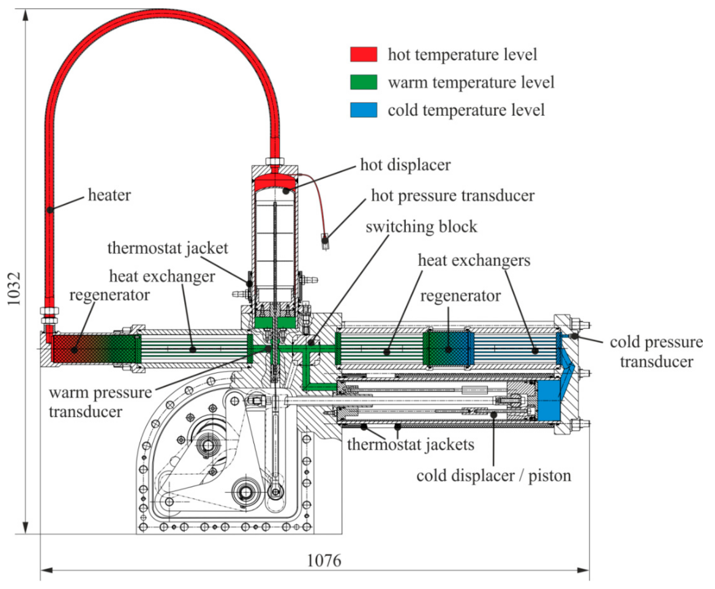
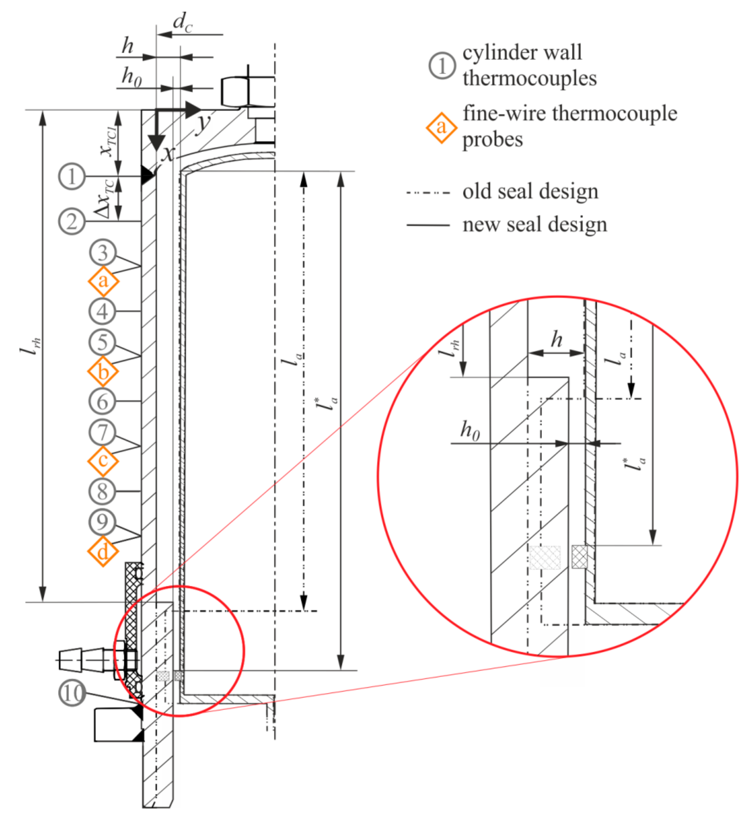
3. Seal Design Modification in the Convertible Laboratory-Scale Machine
4. Results
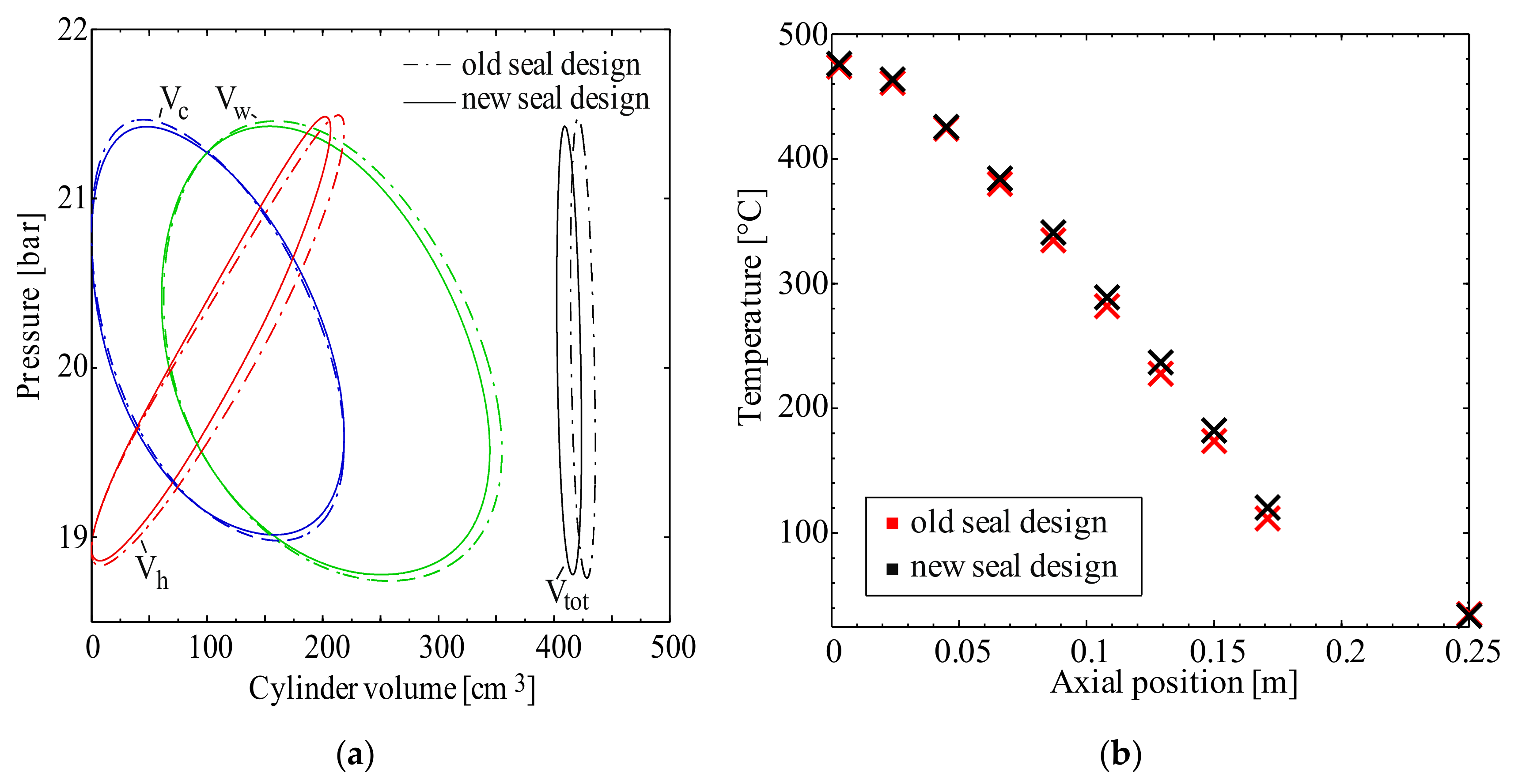
4.1. Heat Balance
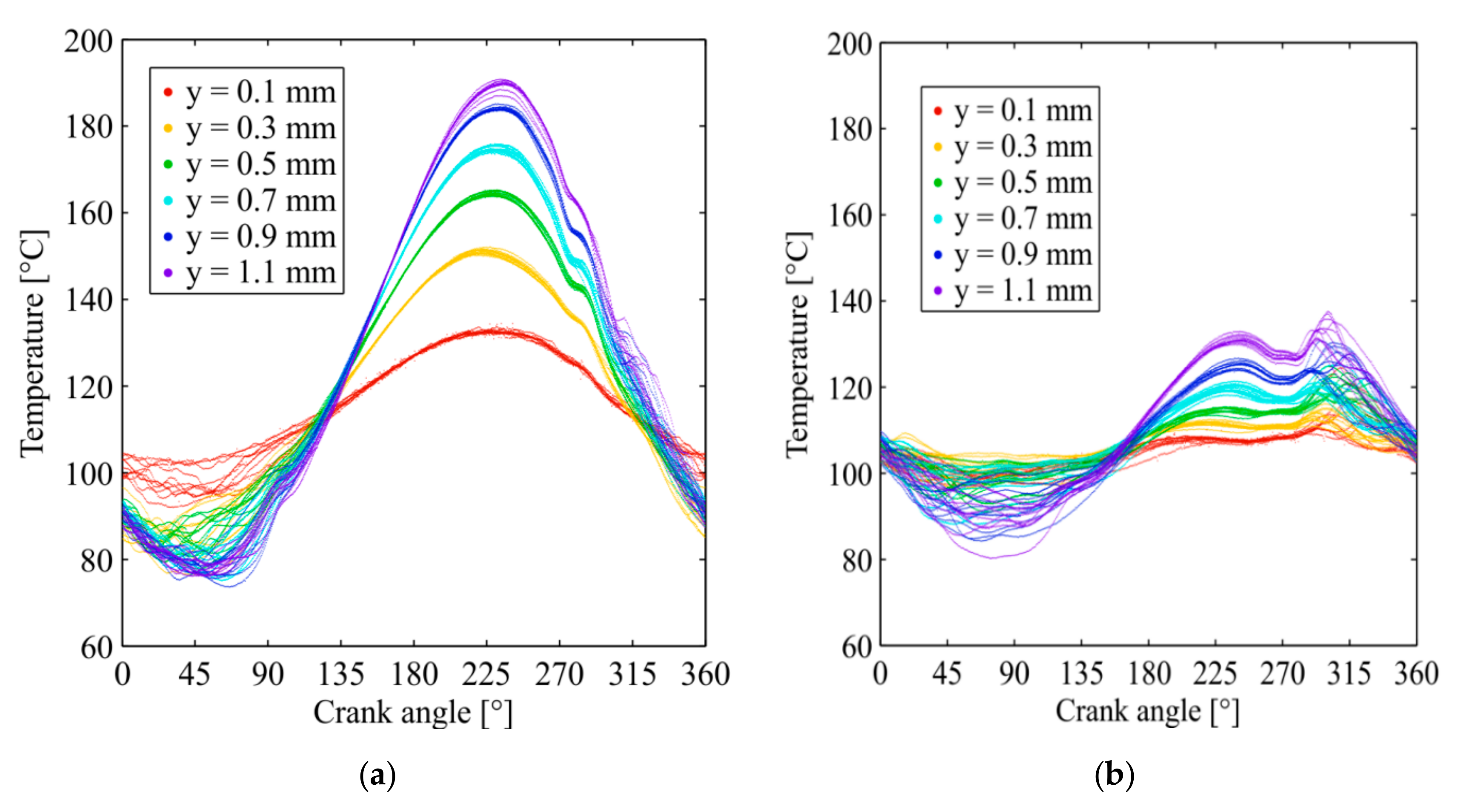
4.2. Gas Temperatures
5. Summary
Author Contributions
Funding
Conflicts of Interest
Nomenclature
| Δ | difference |
| h | appendix gap width (m) |
| l | length (m) |
| n | rotational speed (min−1) |
| p | pressure (bar) |
| rh | gap width ratio |
| T | temperature (°C) |
| V | Volume (m3) |
| Superscripts | |
| ˉ | temporal average |
| Subscripts | |
| a | appendix gap |
| c | cold |
| h | hot |
| TC | thermocouple |
| tot | sum of all cylinder volumes |
| w | warm, intermediate |
References
- Mahkamov, K. An Axisymmetric Computational Fluid Dynamics Approach to the Analysis of the Working Process of a Solar Stirling Engine. J. Sol. Energy Eng. 2006, 128, 45–53. [Google Scholar] [CrossRef]
- Abbas, M.; Said, N.; Boumeddane, B. Thermal analysis of Stirling engine solar driven. Rev. Energies Renouvables 2008, 11, 503–514. [Google Scholar]
- Le’an, S.; Yuanyang, Z.; Liansheng, L.; Pengcheng, S. Performance of a prototype Stirling domestic refrigerator. Appl. Therm. Eng. 2009, 29, 210–215. [Google Scholar] [CrossRef]
- Chen, C.L.; Ho, C.E.; Yau, H.Y. Performance Analysis and Optimization of a Solar Powered Stirling Engine with Heat Transfer Considerations. Energies 2012, 5, 3573–3585. [Google Scholar] [CrossRef] [Green Version]
- Ulloa, C.; Miguez, J.-L.; Porteiro, J.; Eguia, P.; Cacabelos, A. Development of a transient model of a stirling-based CHP system. Energies 2013, 6, 3115–3133. [Google Scholar] [CrossRef]
- Aksoy, F.; Karabulut, H.; Çınar, C.; Solmaz, H.; Özgören, Y.Ö.; Uyumaz, A. Thermal performance of a Stirling engine powered by a solar simulator. Appl. Therm. Eng. 2015, 86, 161–167. [Google Scholar] [CrossRef]
- Qiu, S.; Solomon, L.; Rinker, G. Development of an integrated thermal energy storage and free-piston stirling generator for a concentrating solar power system. Energies 2017, 10, 1361. [Google Scholar] [CrossRef]
- Egas, J.; Clucas, M.D. Stirling Engine Configuration Selection. Energies 2018, 11, 584. [Google Scholar] [CrossRef]
- Ranieri, S.; Prado, A.O.G.; MacDonald, D.B. Efficiency reduction in stirling engines resulting from sinusoidal motion. Energies 2018, 11, 2887. [Google Scholar] [CrossRef]
- Sowale, A.; Anthony, J.E.; Kolios, J.A. Optimisation of a quasi-steady model of a free-piston stirling engine. Energies 2018, 12, 72. [Google Scholar] [CrossRef]
- Heikrodt, K.; Heckt, R. Gasbetriebene Wärmepumpe zur monovalenten Raumbeheizung und Trinkwassererwärmung; BMBF Final Report No. 0326947E; BVE Thermolift GbR: Aachen, Germany, 1999. [Google Scholar]
- Kühl, H.-D.; Rüther, J.; Schulz, S. Experimental Operating Characteristics of Three Different Displacer Systems for Free Piston Vuilleumier Heat Pumps. In Proceedings of the International Stirling Forum, Osnabrück, Germany, 5–6 May 2004. [Google Scholar]
- Geue, I.; Pfeiffer, J.; Kühl, H.D. Laboratory-Scale Stirling-Vuilleumier Hybrid System Part II: Experimental Results. J. Propul. Power 2013, 29, 812–824. [Google Scholar] [CrossRef]
- Dogkas, G.; Rogdakis, E.; Bitsikas, P. 3D CFD simulation of a Vuilleumier heat pump. Appl. Therm. Eng. 2019, 153, 604–619. [Google Scholar] [CrossRef]
- Rios, P.A. An approximate solution to the shuttle heat-transfer losses in a reciprocating machine. J. Eng. Gas. Turb. Power 1971, 93, 177–182. [Google Scholar] [CrossRef]
- Chang, H.M.; Park, D.J.; Jeong, S. Effect of gap flow on shuttle heat transfer. Cryogenics 2000, 40, 159–166. [Google Scholar] [CrossRef]
- Berchowitz, D.; Berggren, R. Appendix Gap Losses in Reciprocating Machines; MTI Report No. 81ASE187ER16; Mechanical Technology Incorporated: Latham, NY, USA, 1981; p. 27. [Google Scholar]
- Magee, F.N.; Doering, R.D. Vuilleumier-Cycle Cryogenic Refrigeration Development; AFFDL-TR-68-67; Air Force Flight Dynamics Laboratory, Wright-Patterson Air Force Base: Greene County, OH, USA, 1968.
- Andersen, S.K.; Carlsen, H.; Thomsen, P.G. Preliminary results from a numerical study on the appendix gap losses in a Stirling engine. In Proceedings of the 12th International Stirling Engine Conference, Durham, NC, UK, 7–9 September 2005; pp. 336–347. [Google Scholar]
- Sauer, J.; Kühl, H.D. Numerical model for Stirling cycle machines including a differential simulation of the appendix gap. Appl. Therm. Eng. 2017, 111, 819–833. [Google Scholar] [CrossRef]
- Nishio, S.; Inada, T.; Nakagome, H. Shuttle Heat-Transfer in Refrigerators. In Transport Phenomena in Thermal Engineering; Su, J.S., Chung, S.H., Kim, K.H., Eds.; Begell House: Danbury, CT, USA, 1993; pp. 484–489. [Google Scholar]
- Huang, S.C.; Berggren, R. Evaluation of Stirling Engine Appendix Gap Losses. In Proceedings of the 21st Intersociety Energy Conversion Engineering Conference, San Diego, CA, USA, 25–29 August 1986; pp. 562–568. [Google Scholar]
- Zimmerman, F.J.; Longsworth, R.C. Shuttle Heat Transfer. In Proceedings of the Cryogenic Engineering Conference, Boulder, CO, USA, 17 June 1970; Advances in Cryogenic Engineering; Springer: Boston, MA, USA, 1971; Volume 16, pp. 342–351. [Google Scholar]
- Harness, J.B.; Newmann, P.E.L. A Theoretical Solution of Shuttle Heat Transfer Problem. In Proceedings of the 4th International Cryogenic Conference, Eindhoven, The Netherlands, 24–26 May 1972; pp. 97–100. [Google Scholar]
- Mabrouk, M.T.; Kheiri, A.; Feidt, M. Effect of leakage losses on the performance of a β type Stirling engine. Energy 2015, 88, 111–117. [Google Scholar] [CrossRef]
- Pfeiffer, J.; Kühl, H.-D. New Analytical Model for Appendix Gap Losses in Stirling Cycle Machines. J. Thermophys. Heat Trans. 2016, 30, 288–300. [Google Scholar] [CrossRef]
- Pfeiffer, J.; Kühl, H.D. Optimization of the Appendix Gap Design in Stirling Engines. J. Thermophys. Heat Trans. 2016, 30, 831–842. [Google Scholar] [CrossRef]
- Thieme, L.G. Low-Power Baseline Test. Results for the GPU 3 Stirling Engine; NASA-TM-79103; NASA Lewis Research Center: Cleveland, OH, USA, 1979.
- Thieme, L.G.; Tew, R.C., Jr. Baseline Performance of the GPU-3 Stirling Engine; NASA TM-79038; NASA Lewis Research Center: Cleveland, OH, USA, 1978.
- Geue, I. Entwicklung, ähnlichkeitstheoretische Skalierung und Untersuchung eines umschaltbaren Systems aus Stirlingmotor und Vuilleumier-Wärmepumpe zur dezentralen Hausenergieversorgung. Ph.D. Thesis, Chair of Thermodynamics. TU Dortmund University, Dr. Hut, München, Germany, 2012. [Google Scholar]
- Kühl, H.-D.; Pfeiffer, J.; Sauer, J. Operating Characteristics of a Laboratory-Scale, Convertible Stirling-Vuilleumier-Hybrid CHP System Including a Reversed-Rotation Stirling Mode. In Proceedings of the 16th International Stirling Engine Conference, Bilbao, Spain, 24–26 September 2014; pp. 294–304. [Google Scholar]
- Sauer, J.; Kühl, H.D. Analysis of unsteady gas temperature measurements in the appendix gap of a stirling engine. J. Propul. Power 2018, 34, 1039–1051. [Google Scholar] [CrossRef]
- Pfeiffer, J.; Kühl, H.D. Review of Models for Appendix Gap Losses in Stirling Cycle Machines. J. Propul. Power 2014, 30, 1419–1432. [Google Scholar] [CrossRef]
- Geue, I.; Kühl, H.D. Design of a Convertible Stirling—Vuilleumier Hybrid System for Demand-oriented Decentralized Cogeneration and Heat Pump Application. In Proceedings of the International Stirling Forum, Osnabrück, Germany, 23–24 September 2006. [Google Scholar]
- Geue, I.; Pfeiffer, J.; Hötzel, J.; Kühl, H.D. Design of an Experimental Convertible Stirling-Vuilleumier Hybrid System Obtained by Similarity-Based Scaling. In Proceedings of the 14th International Stirling Engine Conference, Groningen, The Netherlands, 16–18 November 2009. [Google Scholar]
- Geue, I.; Pfeiffer, J.; Kühl, H.D. Laboratory-scale stirling-vuilleumier hybrid system part i: Application of similarity-based design. J. Propul. Power 2013, 29, 800–811. [Google Scholar] [CrossRef]


| Parameter | Value | Parameter | Value |
|---|---|---|---|
| Heater temperature Th | 500 °C | Displacer stroke amplitude | 21.75 mm |
| Intermediate temperature Tw | 30 °C | Old appendix gap length la | 201 mm |
| Cold temperature Tc (Vuilleumier mode) | 10 °C | New appendix gap length la* | 227 mm |
| Working fluid | Helium | Appendix gap width h | 1.4 mm |
| Rotational speed n | 383 min−1 | Bottom gap width h0 | 0.3 mm |
| Mean pressure | 38.3 bar | Axial position of step lrh | 240 mm |
| Cylinder internal bore | 80 mm | Axial position of thermocouple 1 xTC1 | 30 mm |
| Cylinder wall thickness | 5 mm | Axial thermocouple distance ΔxTC | 21 mm |
| Displacer wall thickness | 1.6 mm | Gap width ratio (new seal design) rh | 0.21 |
© 2019 by the authors. Licensee MDPI, Basel, Switzerland. This article is an open access article distributed under the terms and conditions of the Creative Commons Attribution (CC BY) license (http://creativecommons.org/licenses/by/4.0/).
Share and Cite
Sauer, J.; Kühl, H.-D. Experimental Investigation of Displacer Seal Geometry Effects in Stirling Cycle Machines. Energies 2019, 12, 4215. https://doi.org/10.3390/en12214215
Sauer J, Kühl H-D. Experimental Investigation of Displacer Seal Geometry Effects in Stirling Cycle Machines. Energies. 2019; 12(21):4215. https://doi.org/10.3390/en12214215
Chicago/Turabian StyleSauer, Jan, and Hans-Detlev Kühl. 2019. "Experimental Investigation of Displacer Seal Geometry Effects in Stirling Cycle Machines" Energies 12, no. 21: 4215. https://doi.org/10.3390/en12214215