1. Introduction
Convective heat transfer process exists widely in industrial applications ranging from thermal energy conversion to waste heat recovery, including steam generation, chemical industry, metallurgy industry, agricultural products drying, and etc. [
1]. Enhancing convective heat transfer will make sense for energy saving so as to alleviate the pressure of tremendous energy exhausting rate [
2,
3]. In general, theoretical principles in terms of convective heat transfer enhancement techniques can be simply classified into four major categories: increasing the heat transfer area, destroying and thinning boundary layers, generating swirling and secondary flow, and raising the turbulence intensity [
4,
5,
6]. On the other hand, passive heat transfer enhancement techniques are popular in practical applications due to the essential advantage of no other direct external energy sources required [
7]. In recent years, researchers around the world have proposed kinds of passive heat transfer enhancement techniques, such as treated surfaces, rough surfaces [
8], fins [
9], inserts [
10,
11,
12,
13,
14,
15], coiled tubes [
16], corrugated tubes [
17], and etc. [
4].
As is known, all enhancement techniques bring about the increase of heat transfer, as well as flow resistance [
18]. Due to the demand of high overall thermal hydraulic performance, the heat transfer coefficient should be enhanced as high as possible. Hence, the enhancement technique that causes extra pump power consumption should be applied properly to the local area where the heat transfer enhancement is urgently needed. At present, with the advance of numerical analysis and field measurement techniques, it has been possible to access the local temperature and velocity at a specific point in the domain. The remained key problem is how to enhance the convective heat transfer intensity in the local area. Thus, it is necessary to study the unified mechanism of convective heat transfer enhancement.
In order to reveal the unified mechanism of convective heat transfer enhancement, Guo et al. [
19] proposed a new look at the energy equation of convective heat transfer in 1998. They subsequently suggested a heat transfer enhancement concept that the synergetic effect between temperature gradient and velocity vector should be increased. This concept is the well-known field synergy principle that is a general theory for convective heat transfer enhancement. The field synergy principle and the heat line concept [
20] both make independent contributions to the development of heat transfer theory. The heat line is similar to streamline and its major function is to visualize the heat transfer path, while the field synergy principle is aimed at enhancing convective heat transfer by improving the synergy between velocity and temperature gradient [
6]. In 2002, Tao et al. [
21] extended field synergy principle to elliptic flow and verified this principle with numerical simulation. In 2005, Guo et al. [
22] defined a dimensionless parameter named field synergy number that indicates the synergy performance of the entire domain. Moreover, Liu et al. [
23,
24] proposed the physical quantity synergy between the velocity and pressure gradient in the consideration of reducing power consumption and extended field synergy principle to turbulent flow. Afterwards, He and Tao [
5] carried out a comprehensive review of field synergy principle in convective heat transfer, involving mechanisms, techniques, and performance evaluation. Recently, Liu et al. [
25] revealed the multi-field synergy relations for analyzing physical characteristics of convective heat and mass transfer enhancement based on the conservations of energy, momentum and mass concentration.
With continuous theoretical advances in field synergy principle, this principle was also applied to analyze various practical engineering problems. Kuo et al. [
26] evaluated the enhanced convective heat transfer performance of a wave-like channel in Proton Exchange Membrane Fuel Cells. The results showed that the intersection synergy angle in the straight channel is larger than that in the enhanced flow channel. Wu et al. [
27] numerically investigated the gas side heat transfer enhancement mechanism of longitudinal swirl flow in fin-and-tube exchangers in the view of field synergy principle. Jin et al. [
9] carried out a numerical parametric analysis of H-type finned tube and verified the field synergy principle. Tiwari et al. [
28,
29] applied field synergy principle to effectively evaluate the heat transfer performance of channels in which secondary flow was generated. Hamid et al. [
30] analyzed the field synergy of turbulent heat transfer for ribs roughened solar air heater. In the viewpoint of field synergy principle, Li et al. [
31] explained the reduction mechanism of heat loss caused by natural convection in the solar parabolic dish-engine system. Yao et al. [
32] explored the ultrasound-enhanced silica gel regeneration mechanism with the field synergy analysis of convective heat and mass transfer. In this work, the synergy degrees between the temperature and velocity field can be enlarged due to the ultrasonic mechanical effect. Cao et al. [
33] conducted an investigation on flow and sound fields synergy to reveal the noise propagation mechanism in shell-and-tube heat exchangers. With numerical simulation and theoretical analysis, they found that noise can be reduced by increasing the synergetic effect between flow and sound fields. Wang et al. [
34] conducted a heat transfer performance study of supercritical pressure CO2 in a vertical tube and extended field synergy principle to turbulent convective heat transfer in supercritical pressure fluid flows [
35,
36]. Zhang et al. [
37] enhanced the microwave assisted regeneration of the porous diesel particulate filter with field synergy analyses. It can be also seen some other typical research works related to field synergy principle [
38,
39,
40,
41]. Overall, field synergy principle makes positive contributions to the development of convective heat transfer theory and the structural design of enhancement techniques.
Field synergy angle is an indicator of the synergetic effect between velocity vector and temperature gradient. In addition, it has been used to explain the mechanism of convective heat transfer enhancement successfully. However, analyzing the field synergy angle is not enough for the case where the Reynolds number is varied. From various previous works, it is found that both the mean synergy angle and the Nusselt number usually increase with the increase of Reynolds number [
5]. Besides, in the fully developed laminar circular tube flow with constant wall heat flux, as the Reynolds number increases, the mean synergetic effect is deteriorated while the Nusselt number keeps constant. That is to say, the decrease of field synergy angle may not indicate a high Nusselt number when the velocity magnitude is varied. In addition, although the inlet mean velocity is specified as a constant, the local velocity magnitude may be different at different local point. Hence, analyzing the local synergy angle is not enough for describing the convective heat transfer intensity in the local area. Thus, it is necessary to continue an in-depth study on the mechanism of convective heat transfer enhancement and extend the field synergy principle.
In practical engineering, thermal boundary conditions are specified. The role of an enhancement technique is to change the magnitude and direction of the velocity so as to enhance the heat transfer between working fluid and heat transfer surface. Considering the significant effect of the velocity magnitude on convective heat transfer, it inspires the authors to combine local velocity magnitude and field synergy angle so as to describe the convective heat transfer intensity at a local point. Thus, a novel parameter called heat convection velocity is introduced in this paper and the heat convection velocity is defined as the projection of velocity vector on temperature gradient.
The following discussion is divided into five parts. The field synergy principle is firstly reviewed. Then, the heat convection velocity is introduced based on field synergy principle and the mechanism of convective heat transfer enhancement is studied theoretically. Next, the heat convection velocity is applied to explore the mechanism of convective heat transfer in a smooth circular tube. Subsequently, for enhancing the heat transfer in the smooth circular tube, an insert is invented and the heat convection velocity analysis is carried out to study the mechanism of convective heat transfer in the enhanced tube. In the last part, it gives some conclusions of this paper.
2. Field Synergy Principle
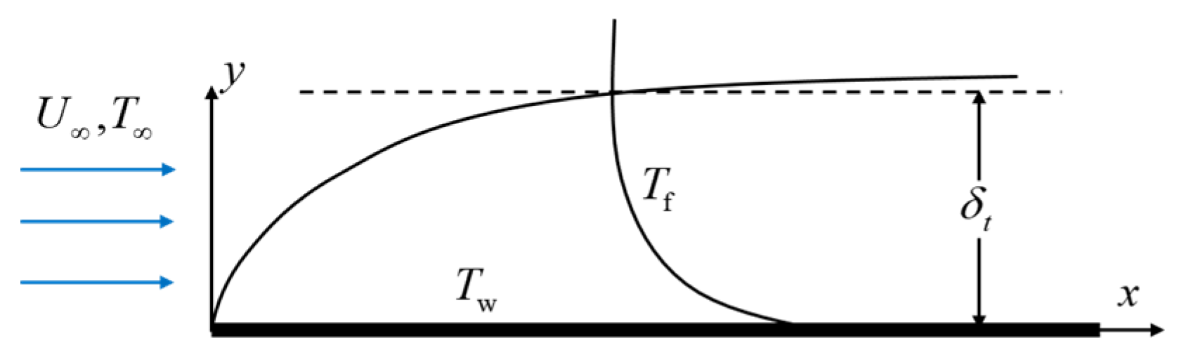
For a two-dimensional steady laminar boundary layer flow in
Figure 1 [
22], the energy equation is shown as
With integrating the above energy equation along the thermal boundary thickness direction, it yields
where
is the thermal boundary layer thickness.
Besides, some common dimensionless variables are defined as
Thus, with the non-dimensional treatment to Equation (2), it yields
where the local synergy angle
of velocity and temperature gradient is defined as
It is shown in Equation (4) that convective heat transfer performance could be greatly enhanced with the increase of cosine value of synergy angle when the velocity magnitude and temperature gradient magnitude are specified. The synergy angle is an indicator of synergetic effect. The better synergy will lead to the larger Nusselt number. Field synergy principle emphasizes the synergy of two field quantities in the domain. Furthermore, field synergy principle implies three aspects of convective heat transfer enhancement [
5,
22]: (a) a small intersection angle between the velocity and temperature gradient; (b) simultaneously large local values of velocity and temperature gradient; (c) and uniform velocity and temperature profiles at the cross section.
The local synergy angle can be used to find the weak synergy region where an enhancement technique is needed. In addition, in the view point of the entire domain, the suggested integration mean synergy angle is defined as [
5]
The mean synergy angle can be used to evaluate the overall synergetic effect. Meanwhile, with transforming Equation (4), another quantity
named field synergy number, which also reflects synergetic effect of the entire domain, is defined as
Moreover, field synergy principle has been also extended and verified in complex elliptic flows recently [
5]. In past works, most of the discussions about field synergy principle were around field synergy angle and synergetic effect. The analysis of field synergy angle is always under the condition of identical Reynolds number, due to the reason that it is not appropriate to compare convective heat transfer performance by field synergy angle when the Reynolds number is varied. However, as a matter of fact, for a heat transfer problem where the thermal boundary is specified, convective heat transfer performance is also dependent on velocity magnitude significantly and the Reynolds number may be varied. More importantly, the local velocity magnitude is varied at different local points in a domain. Thus, field synergy angle analysis is not enough and the velocity magnitude should be considered. Hence, it is necessary to carry out an in-depth study on the mechanism of convective heat transfer enhancement and extend field synergy principle.
3. Heat Convection Velocity
3.1. Definitions
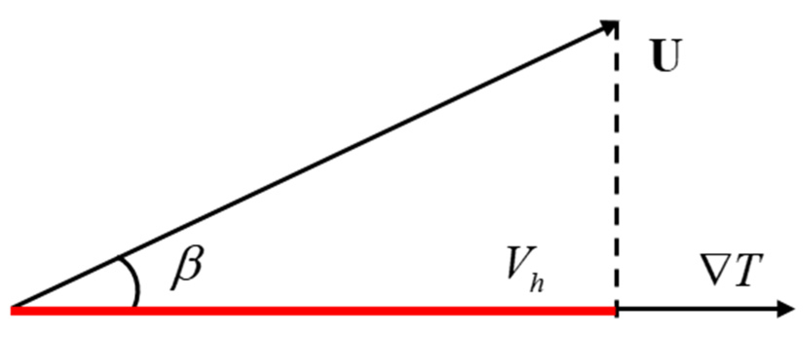
As for convective heat transfer enhancement, there are two direct aspects. On the one hand, the velocity direction can be adjusted so as to improve the synergetic effect. On the other hand, the velocity magnitude can be increased to increase the intensity of synergetic effect. Considering that both the velocity magnitude and synergy angle are important, the authors propose a novel parameter that is the projection of velocity vector on the temperature gradient direction as depicted in
Figure 2. This parameter is called heat convection velocity and reflects the magnitude of the velocity component that contributes to heat convection. It is mathematically defined as
Besides, the mean heat convection velocity of the whole domain can be defined as
The method of increasing the mean heat convection velocity is to increase the velocity and to decrease the synergy angle in the region where the temperature gradient module is high.
On account of that the increase of heat convection velocity directly leads to a larger heat convection term in the energy equation, the heat convection velocity is related to the heat convection intensity. Thus, based on the heat convection velocity, another parameter named heat convection intensity is defined as
In order to describe the overall heat convection intensity, the mean heat convection intensity is defined as
It is worth noting that the unit of heat convection intensity is the same as that of heat transfer coefficient. Both of them can be used as indicators to describe convective heat transfer performance. However, the heat convection intensity is different from the heat transfer coefficient. The heat convection intensity only represents the contribution of fluid flow to heat transfer. And the mathematical relationship between the two parameters is derived with analyzing typical cases in
Section 3.2.
In addition, referring to the definition of Stanton number, this paper proposes a new parameter named heat convection intensity factor that measures the ratio of the mean heat convection intensity to the heat capacity of the fluid. As is known, the heat capacity of the fluid is given as
, where
is the mean inlet velocity that is also used to calculate the Reynolds number. Thus, the expression of heat convection intensity factor (HCIF) can be written as
When heat transfer enhancement technique is used, fluid disturbance is generated. The heat convection intensity factor can be used to evaluate whether the disturbance is conducive to convective heat transfer or not. When the heat convection intensity factor increases more, the heat transfer is enhanced more, which indicates that the imposed disturbance is more efficient. Moreover, the heat convection intensity factor can be regarded as a criterion for the evaluation of convective heat transfer degree. When the heat convection intensity factor is large, the convective heat transfer degree is high, which means that the potential of heat transfer enhancement is less.
3.2. Theoretical Analyses with Heat Convection Velocity
In order to research the mechanism of convective heat transfer enhancement, this paper takes three typical cases of convective heat transfer into consideration. These cases are boundary layer flow, duct flow, and closed cavity flow, respectively. The relationship between Nusselt number and heat convection velocity will be derived in the following.
3.2.1. Case 1: Boundary Layer Flow
The boundary layer flow is depicted in
Figure 1. Substituting the equation
into Equation (4), it yields
Now, with substituting the definition expression of heat convection velocity in Equation (8) into Equation (13), it yields
According to the definition of mean heat convection velocity in Equation (9), Equation (14) can be transformed as
With dimensional analysis, it can be known that the gradient
can be neglected compared with the gradient
in the boundary layer. Thus, it yields
Substituting Equation (16) into Equation (15), the relationship between the heat convection velocity and Nusselt number becomes
In addition, comparing Equation (17) with Equation (11), it can be obtained as
It is shown in Equation (17) that the Nusselt number is proportional to the mean heat convection velocity in the boundary layer flow. That is to say, the method that improves the local heat convection velocity is conducive to convective heat transfer enhancement. Therefore, improving the heat convection velocity is an effective means to enhance convective heat transfer.
On the other hand, the Nusselt number is defined as
Thus, the relationship between heat transfer coefficient and mean heat convection velocity can be expressed as
It indicates that the units of heat convection intensity and heat transfer coefficient are consistent. In particular, in boundary layer flows, the mean heat convection intensity is equal to the heat transfer coefficient.
3.2.2. Case 2: Duct Flow
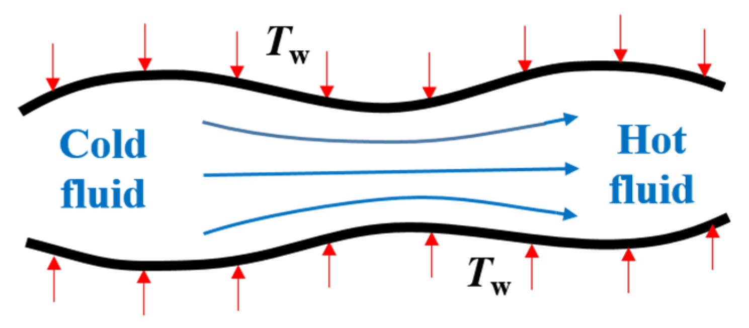
The schematic of duct flow with heat transfer is depicted in
Figure 3. The duct is consisted of an inlet, an outlet, and a heat transfer surface. After passing through the duct from the inlet to the outlet, the cold fluid turns to be hot fluid. Neglecting the viscous dissipation, the energy equation without source term can be written as
With integrating Equation (21) in the domain, it yields
Neglecting the sum of inlet and outlet heat conduction, it yields
On the other hand, the Newton cooling formula is expressed as
where
is the area of the heat transfer surface.
Thus, according to Equation (23) and Equation (24), the heat transfer coefficient can be expressed as
Substituting the expression of mean heat convection velocity in Equation (9) into Equation (25), it is obtained as
Besides, Equation (26) can be also written as
In Equation (27), for a given duct with irregular cross section, the hydraulic diameter
is defined as
where
and
are the area and perimeter of a given cross section, respectively.
The dimensionless temperature gradient can be defined as
Thus, the heat transfer coefficient can be expressed as
In the duct flow, the Nusselt number is defined as
. Thus, the Nusselt number can be expressed as
As is shown in Equation (31), in order to increase the Nusselt number, there are two methods that are increasing the heat convection velocity and increasing the dimensionless temperature gradient. Due to the fact that the temperature boundary is specified, the integration of dimensionless temperature gradient will not change much. Thus, the most direct and efficient way to enhance convective heat transfer in the duct is to increase the mean heat convection velocity. That is to say, increasing the heat convection velocity is conducive to convective heat transfer in duct flow.
3.2.3. Case 3: Closed Cavity Flow
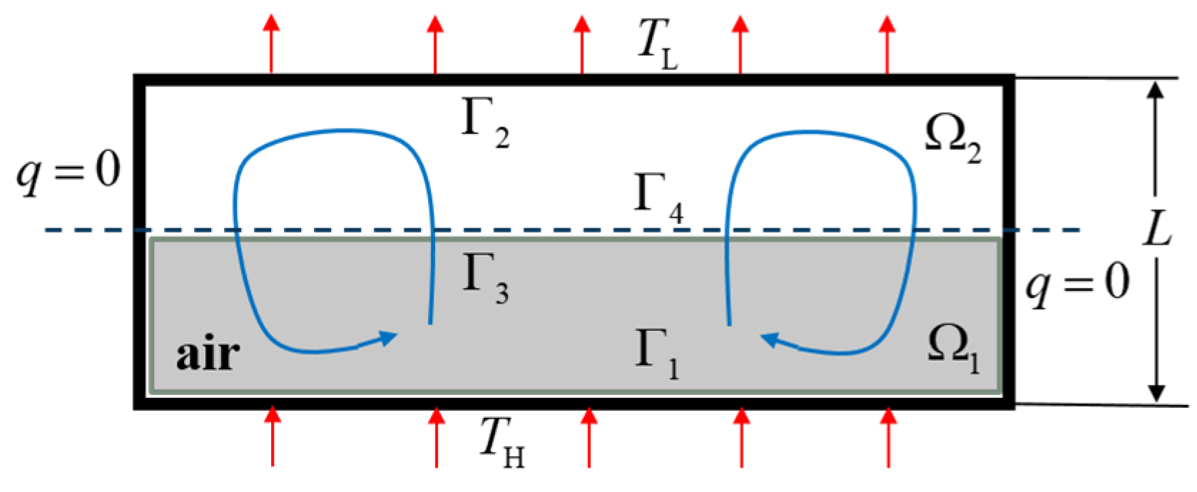
As depicted in
Figure 4, the fluid absorbs heat from the hot wall and then releases an equal amount of heat on the cold wall. The transferred heat can be expressed as
Integrating the energy equation in the domain
, it yields
Substituting the expression of heat convection velocity into Equation (33), it yields
Now, comparing Equation (34) with Equation (32), it is obtained as
When the heat convection is intense enough at the
, the heat conduction can be neglected. Thus, the heat transfer coefficient can be expressed as
The dimensionless temperature gradient is defined as
Thus, the Nusselt number can be expressed as
Similar to the analysis in the duct flow, it is known from Equation (38) that the increase of heat convection velocity is conducive to the heat transfer enhancement.
3.3. The Meaning of Heat Convection Velocity
Firstly, heat convection velocity is an extension of the field synergy principle. It is defined as the projection of the velocity vector on the temperature gradient vector, which is the effective velocity that is conducive to heat convection. A larger heat convection velocity demands a smaller synergy angle and a larger velocity magnitude. In this way, field synergy analysis is extended to the study of heat convection intensity, not just that of field synergy angle. Thus, field synergy analysis is also applicable when the velocity magnitude is varied.
Secondly, the heat convection intensity is proportional to the heat convection velocity. When the heat convection velocity is reduced to zero, the convection term of energy equation becomes zero, indicating that there is no heat convection. The heat convection velocity can be used to find the local areas where the heat convection intensity is weak. And heat transfer enhancement techniques can be designed to amplify the heat convection velocity so as to enhance the heat transfer in these areas, which is helpful to improve the design efficiency.
Thirdly, as shown in Equation (17), Equation (31), and Equation (38), the Nusselt number can be enhanced by increasing the mean heat convection velocity and the dimensionless mean temperature difference. Thus, the mechanism of convective heat transfer enhancement is to increase the mean heat convection velocity and the dimensionless mean temperature difference. Besides, increasing the mean heat convection velocity can be regarded as an efficient method for convective heat transfer enhancement. That is to say, the overall synergetic effect should be improved. In addition, the heat convection velocity can be also amplified by increasing the local velocity in the boundary region where the temperature gradient is always large. In other words, the fluid with lower temperature gradient should be guided to the region where the temperature gradient is higher. Moreover, when the temperature gradient is always larger than zero or less than zero, the term will reach minimum, which is not benefit for heat transfer enhancement. In order to increase the dimensionless mean temperature difference, the term should be amplified. Obviously, an effective method is to adjust the temperature gradient to be sometimes larger than zero and sometimes less than zero in the cross section. In other words, the temperature distribution should be an interphase distribution of hot and cold fluid.
Fourthly, the heat convection intensity factor can be used to describe the enhancement degree of the current heat transfer enhancement technique. If the heat transfer intensity factor is small, there is much potential of heat transfer enhancement. It is necessary to invent other more efficient heat transfer enhancement techniques for this case.
4. Application in Smooth Circular Tube
In this part, this paper concentrates on the study of the relationship between the Nusselt number and heat convection intensity in the smooth tube. The heat convection velocity is used to explore and explain the mechanism of the variation of Nusselt number in the smooth tube. In addition, with mathematical analysis, the heat convection intensity factor is also investigated in the smooth tube.
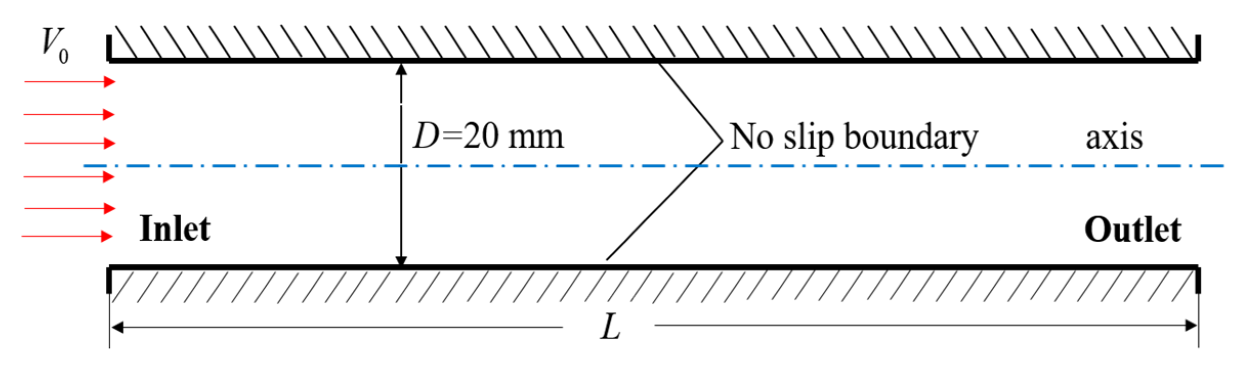
The circular tube is one of the commonly used heat transfer units in the industry. The schematic of the simulation model is depicted in
Figure 5. In the circular tube, the Reynolds number is expressed as
where
is the mass flow rate of a given cross section.
The Nusselt number is expressed as
where
is the mean temperature difference between wall and fluid.
The friction factor is defined as
Besides, the thermal physical parameters of working fluids are listed in
Table 1.
The Reynolds number ranges from 300 to 1800, and the tube flow is laminar flow. Besides, the constant wall temperature boundary and constant wall heat flux boundary are imposed on the tube wall, respectively. On this basis, both the entrance region and the fully developed region are discussed respectively. The overall simulation is carried out based on the commercial software FLUENT 16.0. The grid of the computational domain is generated by the commercial software Gambit 2.4.6. And the grid is dense and independent. The finite volume formulation is used to discretize the governing conservation equations with second order discretization scheme for pressure and second order upwind discretization scheme for energy and momentum. The SIMPLE algorithm [
42,
43,
44] is used to solve the puzzle of pressure-velocity coupling. When the relative energy residual value is less than 10
-8 as well as others are less than 10
−6 or all relative residual values keep constant, the calculation is considered to be converged at the proper results.
4.1. Results Verification
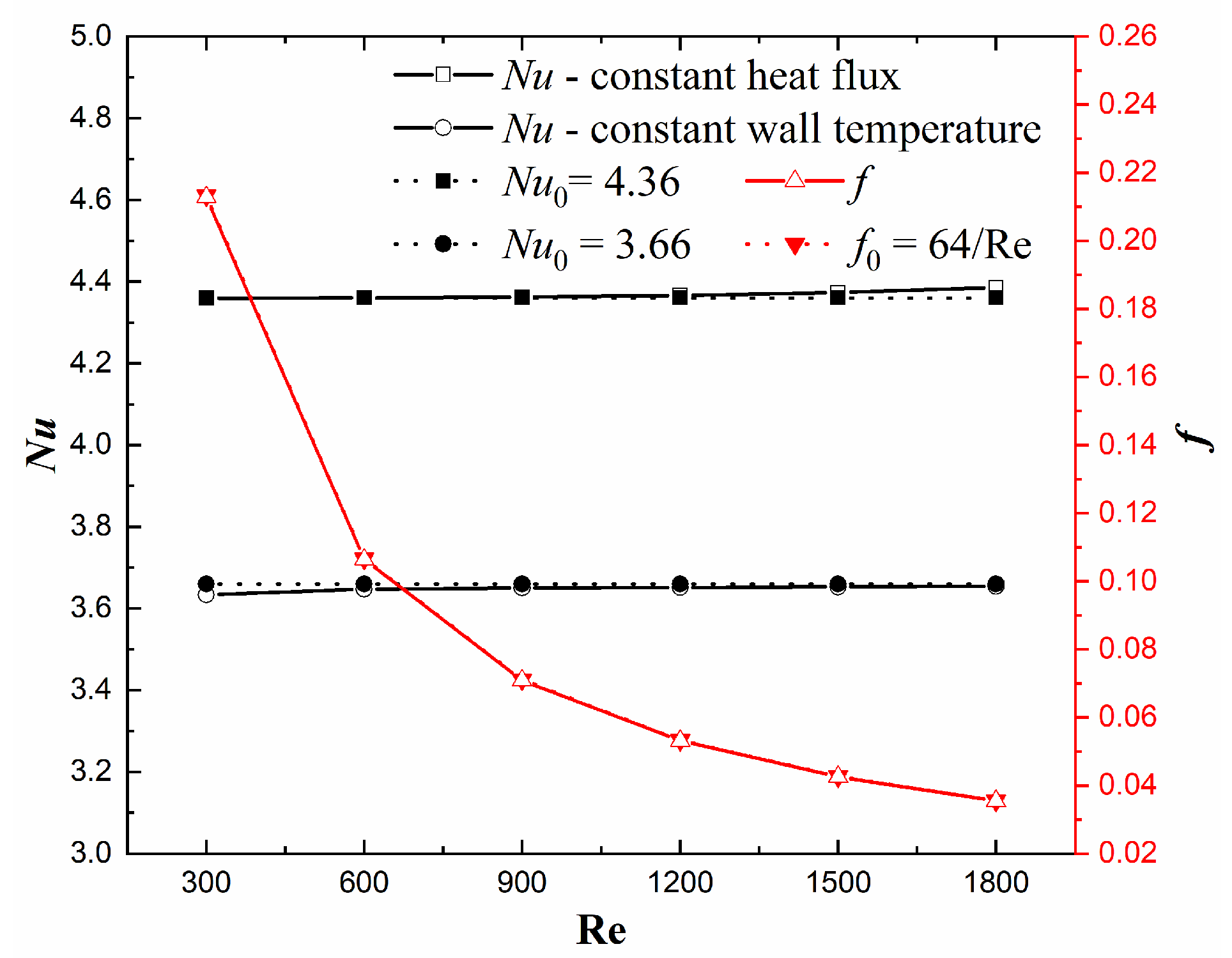
It is necessary to verify the simulation results accuracy before results discussion. The verification method is to compare the numerical results with the corresponding theoretical values in the fully developed laminar flow. In this paper, Nusselt number and friction factor are selected as verification indicators. The working fluid is chosen as water, and the numerical results are taken from the fully developed region of a 20 mm diameter circular tube. The theoretical Nusselt number and friction factor are given in Reference [
45]. As is depicted in
Figure 6, the computational results agree well with the theoretical formulas. It demonstrates that the present computational solution is accurate enough.
4.2. Fully Developed Tube Flow
The numerical results are taken from the fully developed region of a 20 mm diameter circular tube with choosing working fluid as water. As is shown in
Figure 7, the Nusselt number keeps almost unchanged with the increase of Reynolds number in the fully developed laminar flow, no matter with imposing constant heat flux boundary or constant wall temperature boundary. It means that the heat transfer performance is not improved with increasing the Reynolds number. In order to explore the original reason, the variation of mean heat convection intensity is also displayed in
Figure 7. The heat convection intensity also keeps unchanged as the Reynolds number increases, which indicates that the heat convection velocity is not increased as the inlet mean velocity increases. In other words, the increased velocity has no contribution to convective heat transfer due to the unchanged heat convection velocity. Thus, the Nusselt number remains unchanged in the fully developed laminar flow even though the Reynolds number increases. In addition, the heat convection intensity under the constant heat flux boundary is more intense than that under the constant wall temperature, which leads to a larger Nusselt number under the constant heat flux boundary.
4.3. Developing Entrance Flow
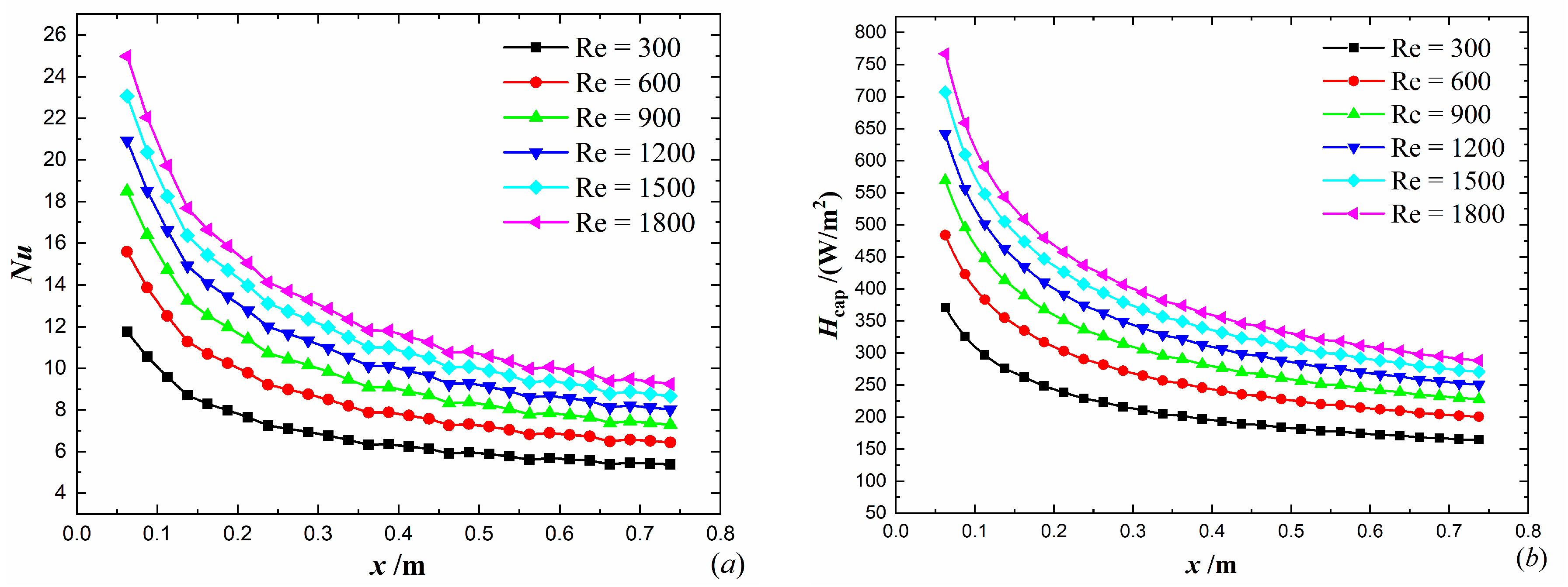
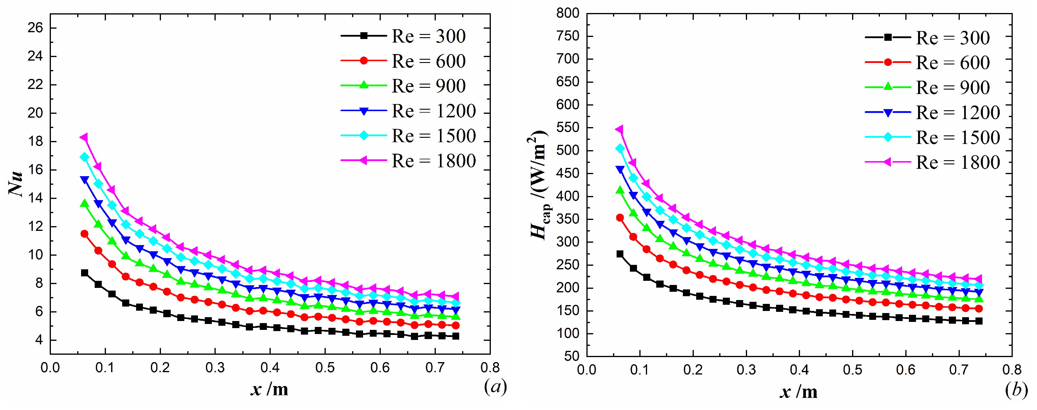
The numerical results of the developing entrance flow are taken from an 800 mm long circular tube where the uniform velocity and temperature are specified at the inlet. The diameter is 20 mm, and water is selected as the working fluid. As is shown in
Figure 8a and
Figure 9a, the Nusselt number decreases along the flow direction of the circular tube at an identical Reynolds number. The reason is attributed to the variation of heat convection velocity. At the inlet, the temperature and velocity are both specified as uniform value, which leads to a better synergetic effect and a larger heat convection velocity. Along the flow direction, the synergetic effect is deteriorated so that the heat convection velocity is decreased, which causes the decrease of Nusselt number. Besides, as the Reynolds number increases, the inlet mean velocity is increased so that the heat convection velocity is increased in the developing entrance flow region, which leads to a larger Nusselt number. In addition, the variation of Nusselt number is similar to that of heat convection intensity. It demonstrates that the increase of heat convection velocity is conducive to the increase of Nusselt number.
4.4. Heat Convection Intensity Factor
A smaller heat convention intensity factor indicates that the heat transfer enhancement technique is more urgently needed for the present heat transfer unit. It is a meaningful work to study the heat convection intensity factor and search for the corresponding influence factors in the smooth tube. For the sake of convenience, the fully developed laminar circular tube is taken into consideration, and the constant heat flux thermal boundary is imposed on the tube wall.
Neglecting the sum of inlet and outlet heat conduction, it yields
where
is the heat flux imposed on the tube wall.
Besides, the denominator of the mean heat convection velocity can be expressed as
where
,
, and
are temperature gradients. Referring to Refs. [
45,
46,
47], their expressions are given as
With introducing dimensionless parameter
, it yields
When
is large, it yields
Hence, the Equation (48) can be simplified as
The mean heat convection velocity is expressed as
Thus, the heat convection intensity factor of the fully developed laminar circular tube with imposing constant heat flux on the wall can be expressed as
The similar result can be obtained when the constant wall temperature thermal boundary is imposed on the tube wall. And when the Prandtl number and Reynolds number are specified, the heat convection intensity factor is less than that under the constant heat flux boundary. As a result, the heat convection intensity factor of the smooth tube is at least related to the boundary condition, Prandtl number, and Reynolds number. With the increase of Reynolds number and Prandtl number, the heat convection intensity factor may be decreased. It means that the heat transfer enhancement technique could be more necessary when Reynolds number and Prandtl number increase.
5. Application in Heat Transfer Enhancement Tube
It is still a big challenge till now to invent an efficient heat transfer enhancement structure that can harvest high heat transfer performance with moderate flow resistance. In this part, the heat convection velocity is applied to guide the design of the heat transfer enhancement technique in the circular tube. Then, the thermal hydraulic performance is investigated. Furthermore, the enhancement mechanism will be also explored with heat convection velocity analysis.
In addition, the evaluation criterion R3 [
48] is an indicator of overall thermal hydraulic performance at an identical pump power consumption, which is defined as
where
is the Nusselt number of the smooth tube at the equivalent Reynolds number
. Given a constant pump power consumption, the equivalent Reynolds number
can be calculated with
The relationship between
and
is given as
In order to evaluate the resistance reduction performance, the criterion EEC is adopted and defined as
The following numerical results are taken from the stable region of a long tube. The inlet velocity and temperature profiles are taken from the results of the corresponding periodic simulation. In addition, the numerical method is verified in the above section.
5.1. Structure Design
According to the theoretical analysis of heat convection velocity, the heat transfer enhancement technique should satisfy three points: (a) the overall synergetic effect should be improved so as to enlarge the mean heat convection velocity; (b) the fluid with low temperature gradient in the core flow region should be guided to the boundary region where the temperature gradient is high so that the mean heat convection velocity can be improved; (c) temperature distribution should be an interphase distribution of hot and cold fluid so as to increase the dimensionless temperature difference.
According to the previous works [
10,
11,
12,
13], it is gratifying that the longitudinal swirl flow can be generated and bring in moderate flow resistance when the incoming fluid passes by an inclined rod or plate. Thus, a new insert is proposed as depicted in
Figure 10. The inserts are wedge shaped plates and mounted on a long rod. This structure can be easily manufactured by 3D printing technology. The longitudinal swirl flow can be generated to improve the overall synergetic effect so as to enlarge the mean heat convection velocity in the circular tube. Besides, the core flow can be guided to scour the wall, which increases the velocity magnitude in the boundary region and enlarges the mean heat convection velocity. In addition, the dimensionless temperature difference may be increased due to the exchange of cold and hot fluid.
5.2. Thermal Hydraulic Performance Evaluation
The thermal hydraulic performance of the enhanced tube is investigated when different boundary condition and different working fluid are chosen. In
Figure 11, with selecting water as the working fluid, it is depicted the variation of thermal hydraulic performance with the increase of Reynolds number when two typical kinds of thermal boundaries are respectively specified at the tube wall. It is found that the enhanced thermal performance is better with the thermal boundary condition of constant wall temperature at an identical Reynolds number. It is depicted in
Figure 12 that the thermal hydraulic performance is varied with selecting different working fluid. In order to investigate the effect of working fluid on the enhanced performance, the thermal boundary condition at the tube wall is specified as constant wall temperature, and the working fluid is selected as water, oil, and air, respectively. As seen in
Figure 12, the thermal hydraulic performance is the best when selecting oil as working fluid, and the thermal hydraulic performance is the worst when selecting air as working fluid. It is also shown in
Figure 11 and
Figure 12 that both R3 and EEC are higher and larger than 1 in most cases, which indicates that the design of the present inserts is effective. The mechanism analysis of heat transfer enhancement will be carried out in the following.
5.3. Heat Convection Velocity Analysis
According to Equation (31), the Nusselt number of the circular tube can be expressed as
where
is the dimensionless mean temperature difference in the circular tube.
Thus, the enhanced ratio of Nusselt number is expressed as
As is shown in Equation (59), there are two aspects for enhancing the Nusselt number. One is to increase the mean heat convection intensity, the other is to form suitable temperature distribution so as to increase the dimensionless mean temperature difference. The enhanced ratios of
,
, and
at Re = 600 are depicted in
Figure 13,
Figure 14, and
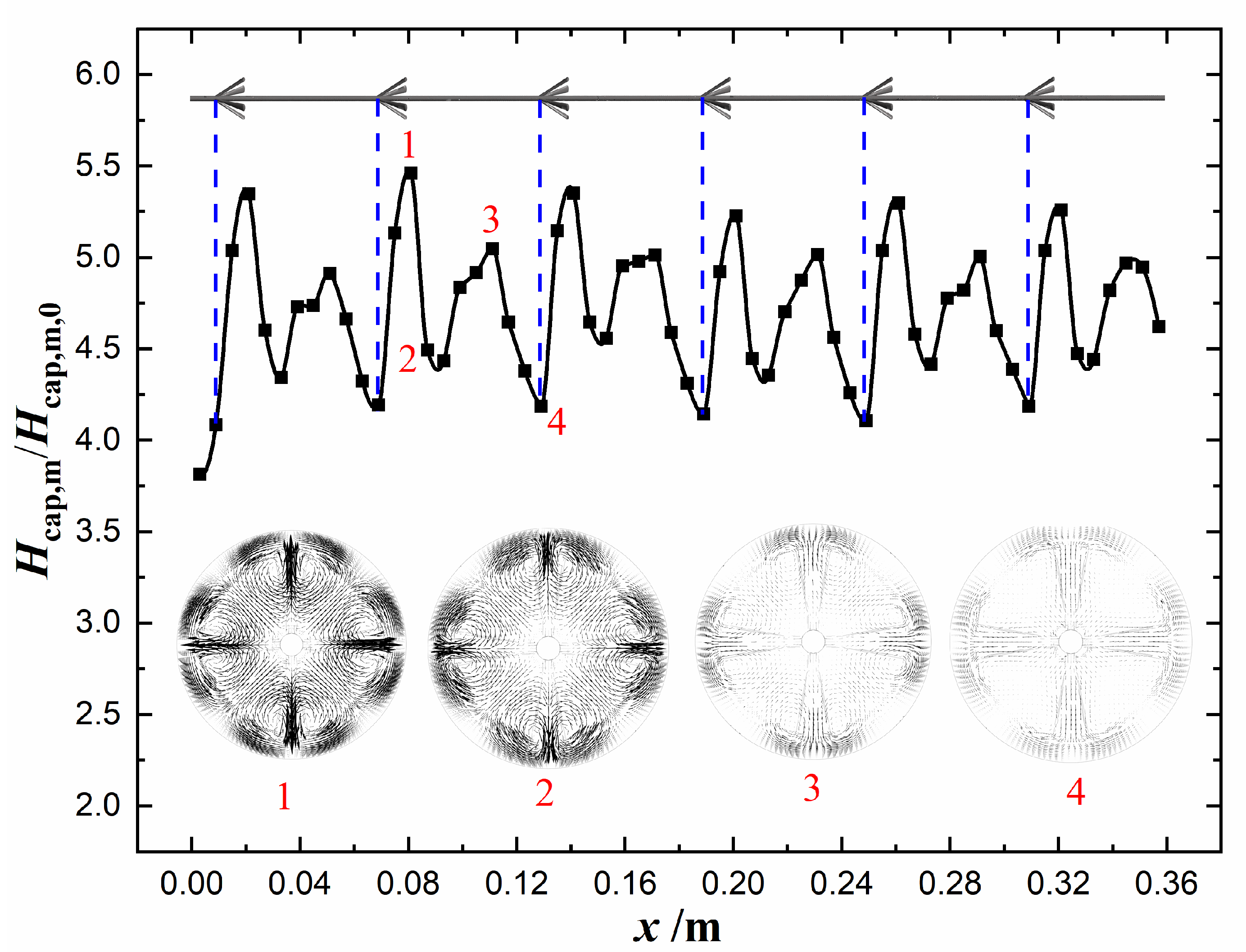
Figure 15, respectively. Water is selected as the working fluid, and the constant wall temperature thermal boundary condition is specified at the tube wall. As is shown, the mean heat convection intensity is enhanced much more than the dimensionless mean temperature difference, which indicates that the improvement of Nusselt number is mainly due to the enhancement of the mean heat convection intensity. Besides, the tangential velocity distributions at four cross sections are displayed in
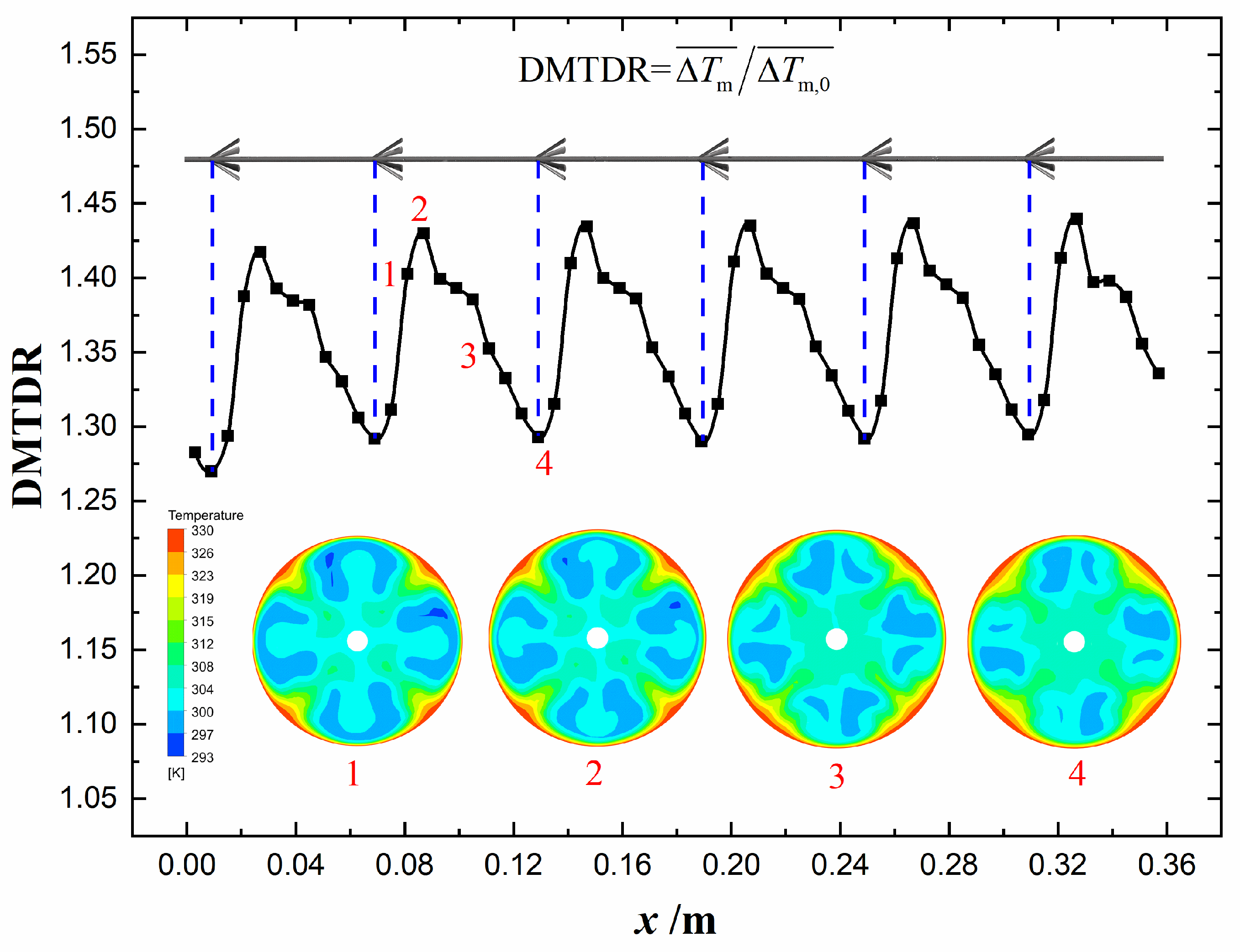
Figure 14. It indicates that the longitudinal swirl flow is generated in the circular tube, which leads to the increase of heat convection intensity. In addition, the temperature distributions at the corresponding cross sections are displayed in
Figure 15. It indicates that the interphase arrangement of hot and cold fluids is conducive to the enhancement of dimensionless mean temperature difference.
In short, the enhanced Nusselt number is owing to two reasons. On the one hand, the longitudinal swirl flow increases the heat convection intensity. On the other hand, the temperature distribution leads to the increase of dimensionless mean temperature difference.
The heat convection intensity factors are depicted in
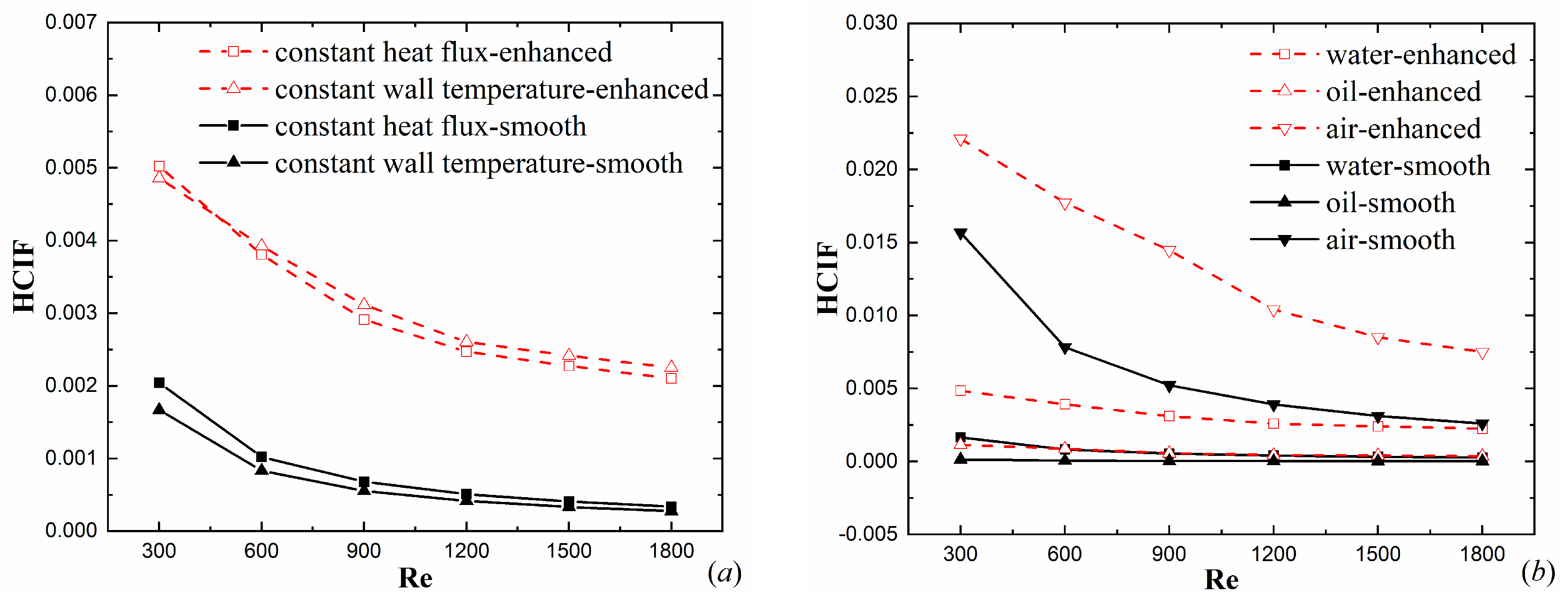
Figure 16. Obviously, the heat convection intensity factor of the enhanced tube is larger than that of smooth tube at an identical Reynolds number. The main reason is that the heat convection velocity in the enhanced tube is increased because of efficient disturbance. Under the condition of applying the same heat transfer enhancement techniques, when the heat convection intensity factor of smooth tube is smaller, the ratio of heat convection intensity factor of the enhanced tube to that of the smooth tube may be larger, which indicates that the heat transfer may be enhanced more significantly. On the other hand, when the heat convection intensity factor of the smooth tube is small, the convective heat transfer degree is low, which means that the potential of heat transfer enhancement is large. As depicted in
Figure 16a, when specifying constant wall temperature thermal boundary at the tube wall, the heat convection intensity of the smooth tube is smaller compared with specifying constant heat flux boundary at the tube wall, which reveals the reason that the enhanced times of heat transfer performance is higher under constant wall temperature boundary condition. Similarly, in
Figure 16b, when the working fluid is selected as oil, the heat convection intensity factor of the smooth tube is the smallest so that the corresponding enhanced heat transfer performance is the best. In addition, though the heat transfer enhancement technique is used, the heat convection intensity factor is still small. It means that there is still much potential of enhancing convective heat transfer by increasing the heat convection velocity. Thus, the key point of heat transfer enhancement should be placed on increasing the mean heat convection velocity.


