Design of an Electromagnetic Variable Valve Train with a Magnetorheological Buffer


Abstract
:1. Introduction
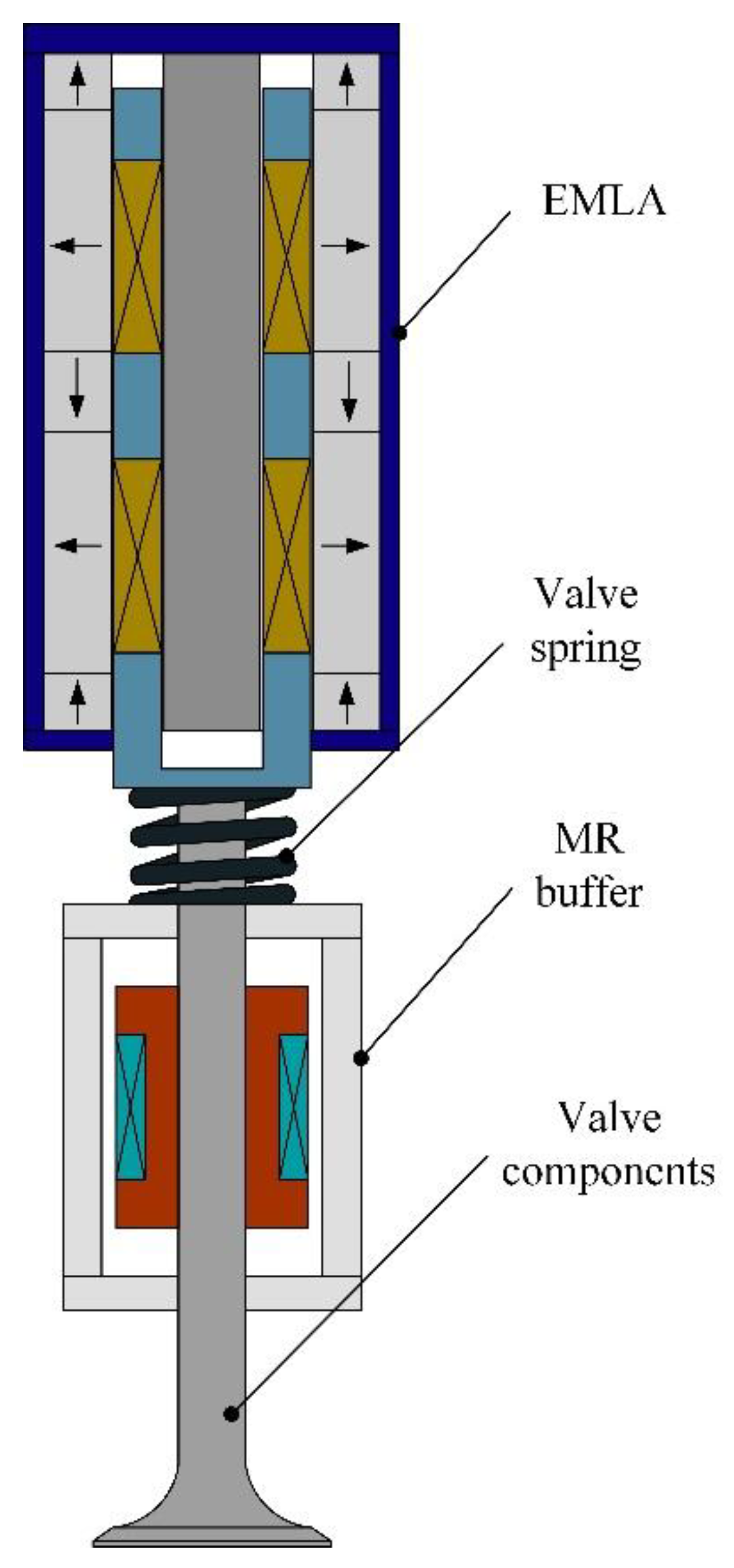
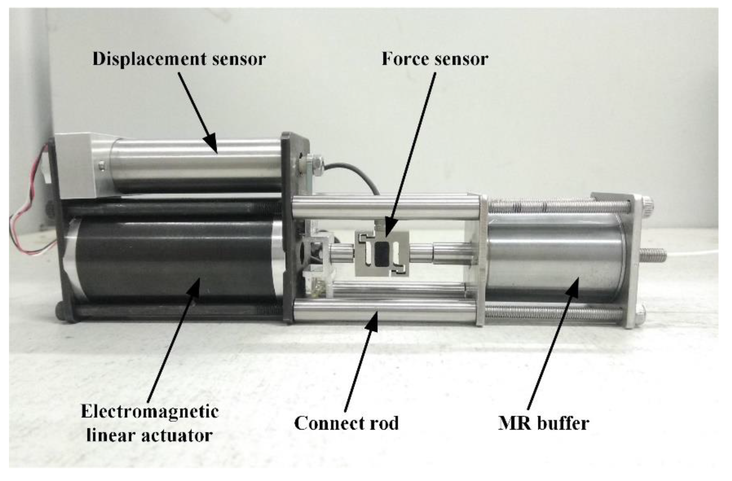
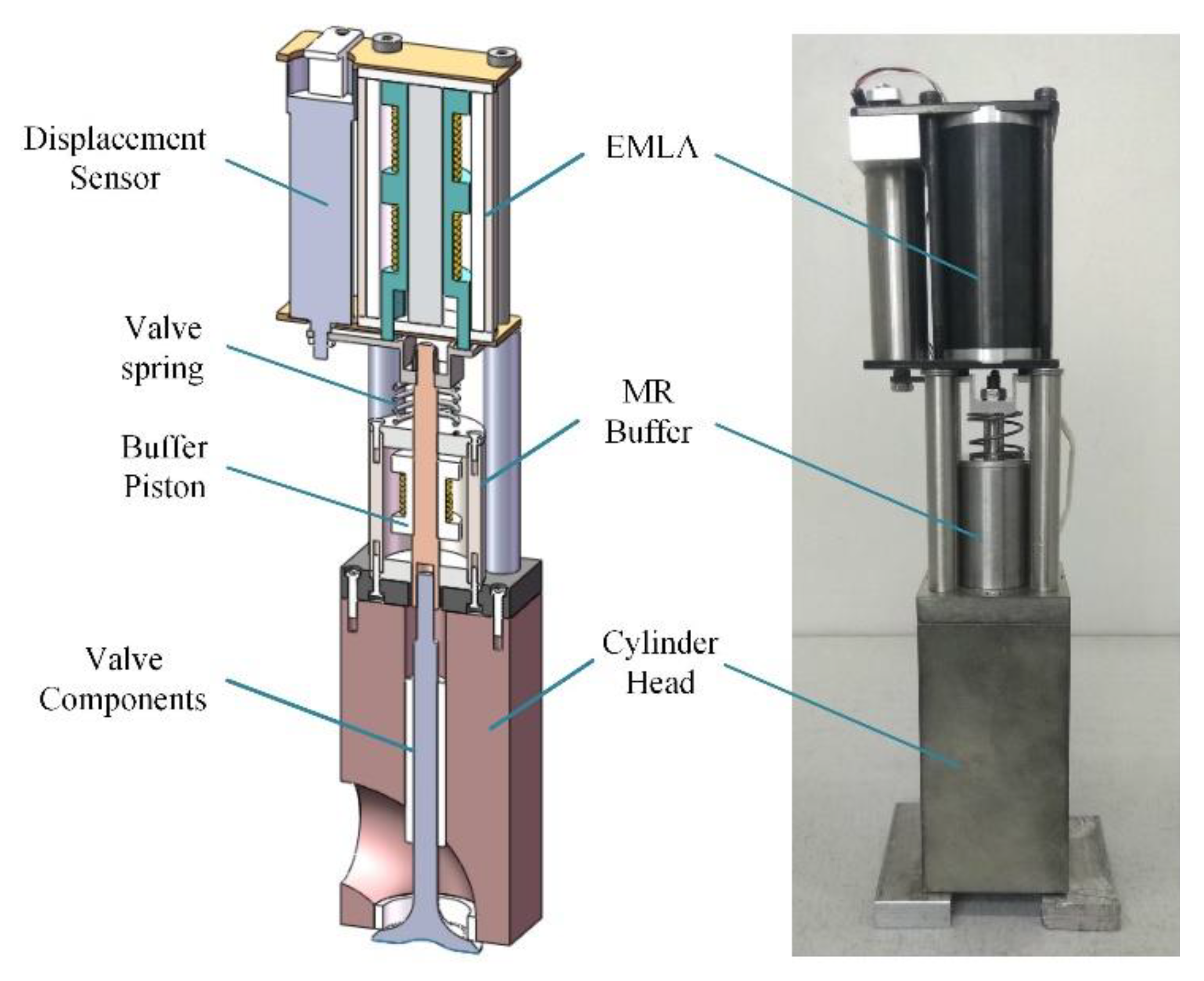
2. System Overview
- It has a large mechanical damping coefficient, which can overcome the influence of external interference and parameter changes.
- The valve seating velocity is controlled within 0.1 m/s. The EMLA and MR buffer is controlled by the control unit, and the seat velocity of the valve is reduced by the MR buffer to ensure the valve seat velocity is effectively controlled.
3. Structure Design
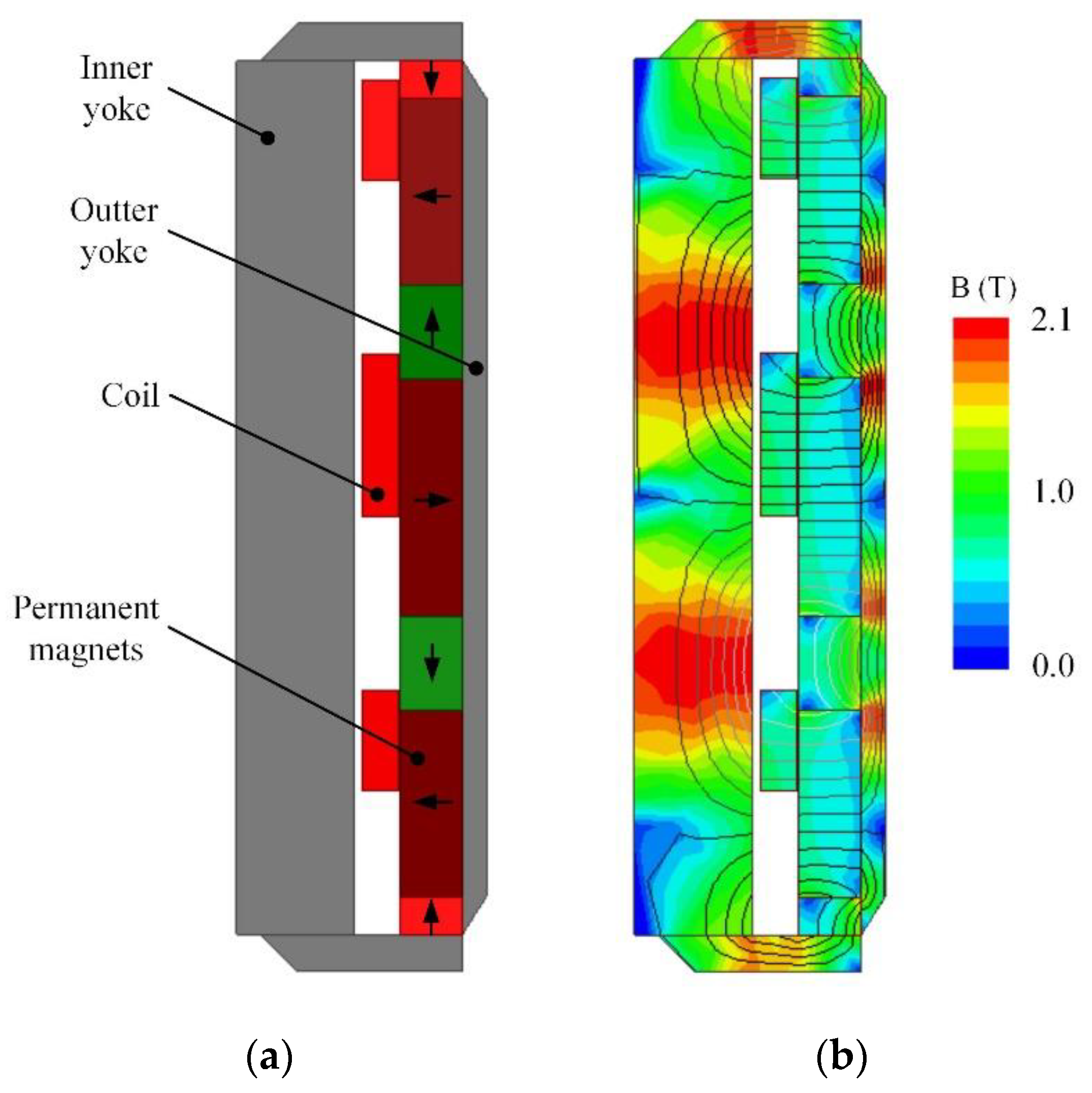
3.1. Structure Design of the Electromagnetic Linear Actuator
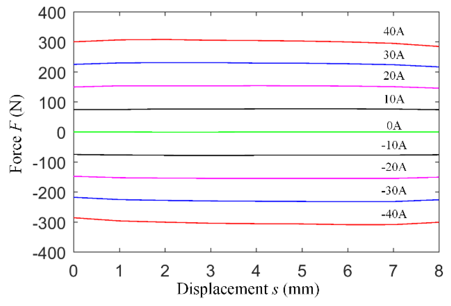
- When the engine operates under high load, the pressure difference between the cylinder and the exhaust port can reach up to 8 bar when the exhaust valve is opened in the exhaust stroke [22]. Therefore, the maximum electromagnetic force of the EMLA needs to be over 300 N to ensure that the valve can be opened effectively.
- In order to meet the requirements of the engine at high speed, the valve transition time (from 5% of the valve lift to 95% of the time experienced) can reach 4 ms, or even faster.
- The EMLA is installed on the cylinder head of the engine, so the diameter and height should be limited to 40 mm and 70 mm, respectively, and can achieve a maximum power output under the volume limitation.
- The change of the mover position should have less influence on the electromagnetic force of the EMLA.
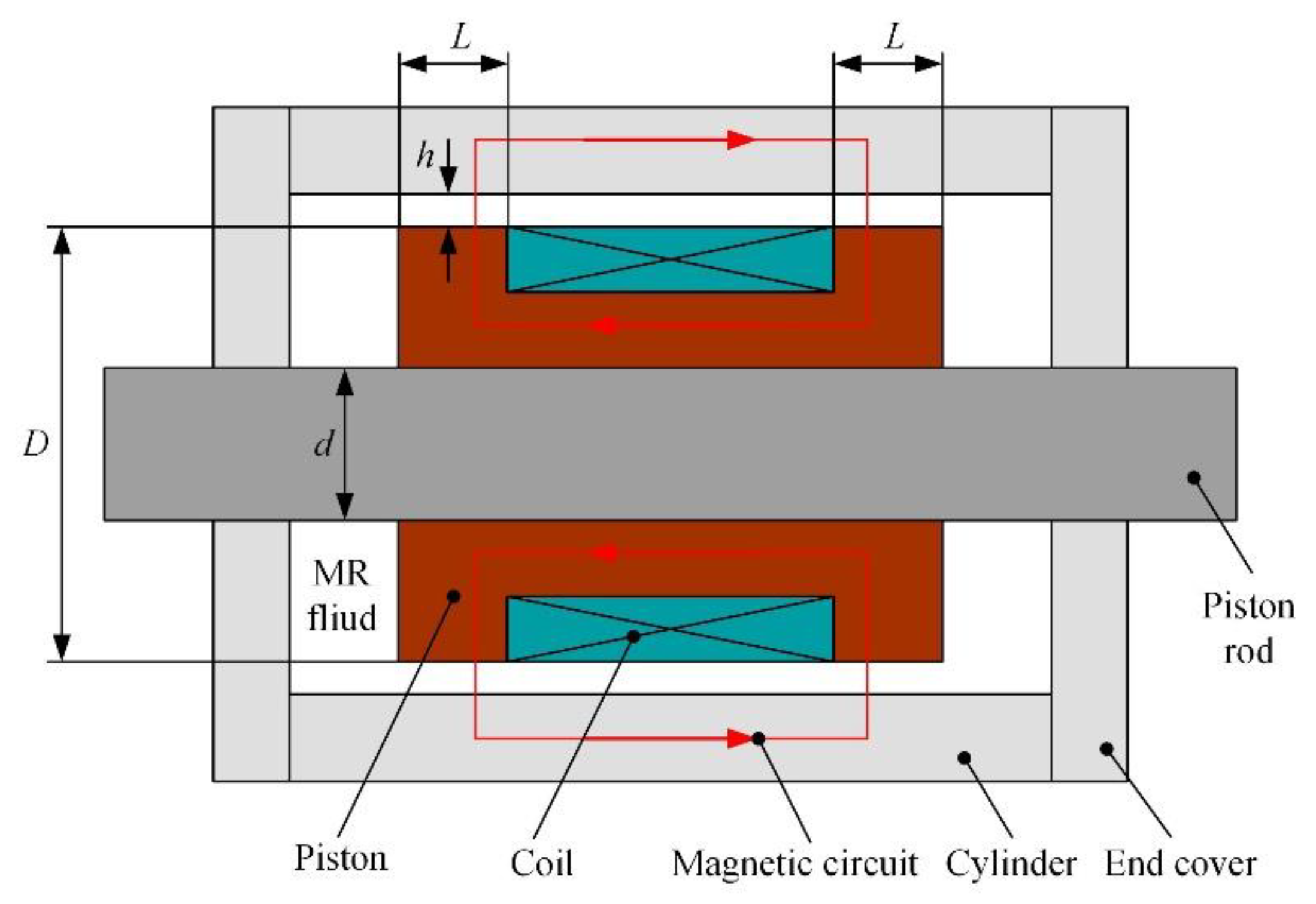
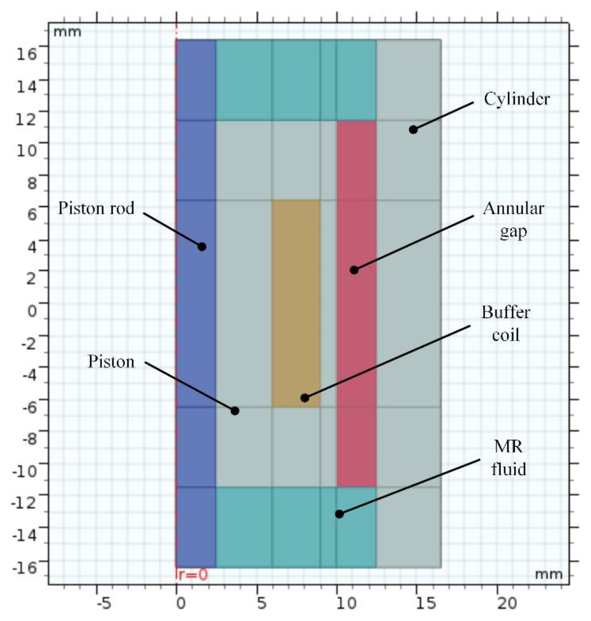
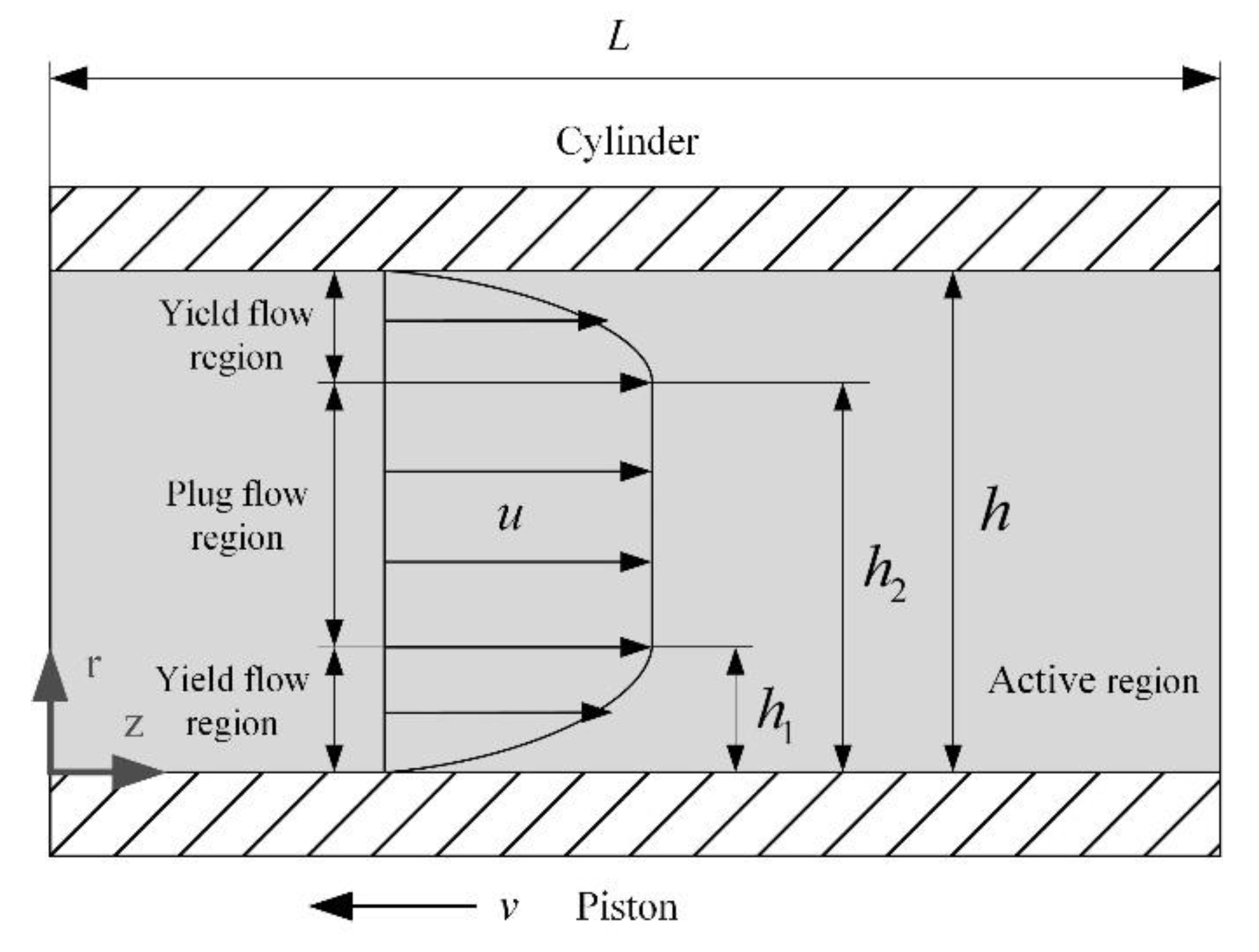
3.2. Structure Design of MR Buffer
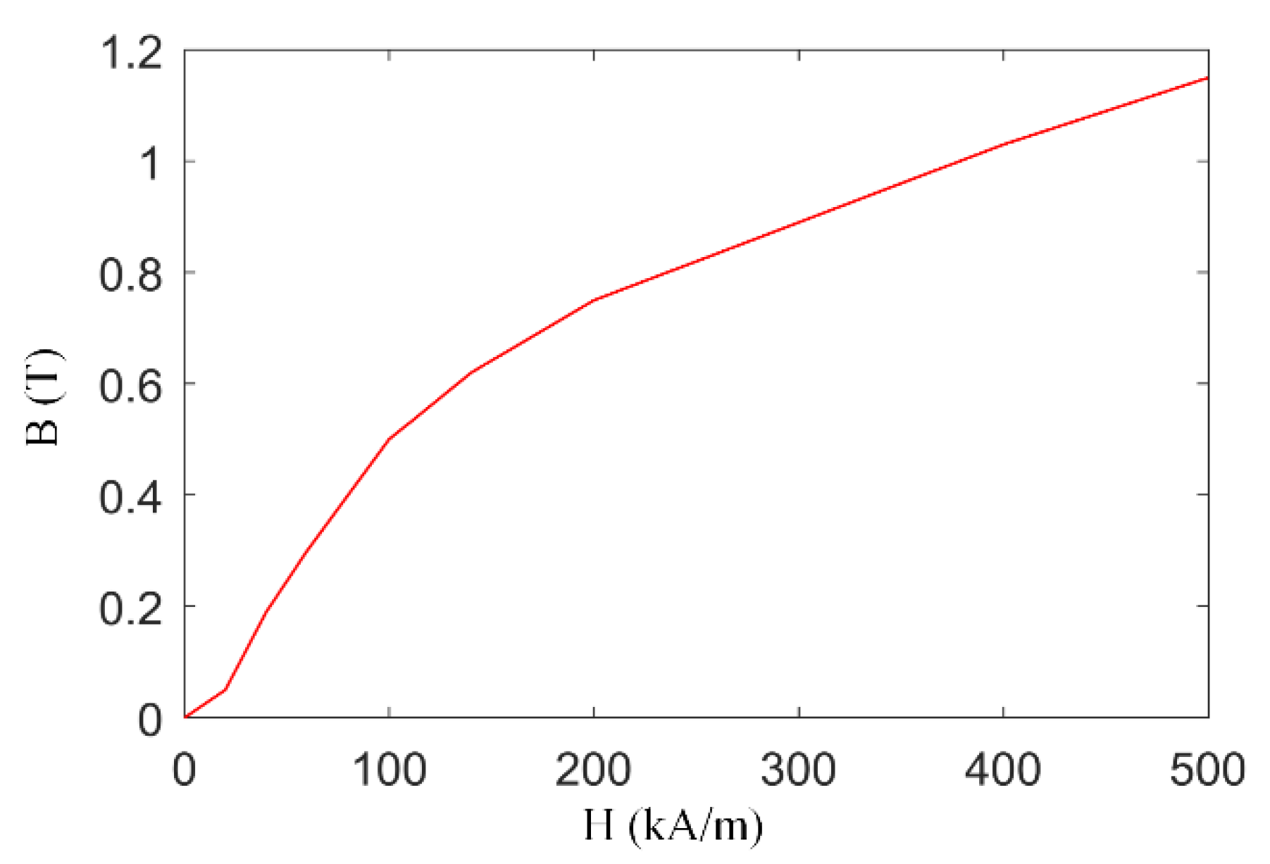
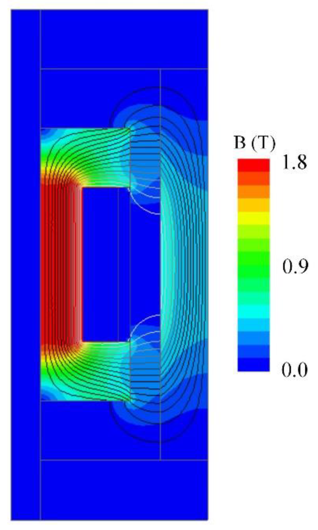
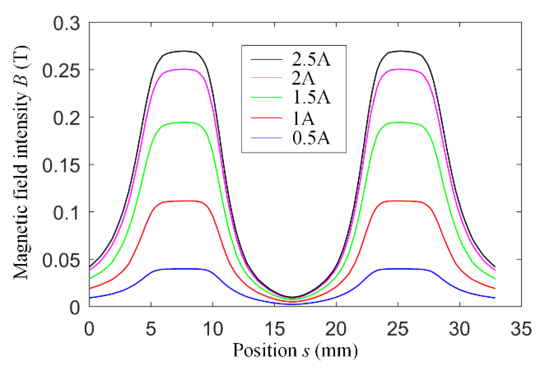
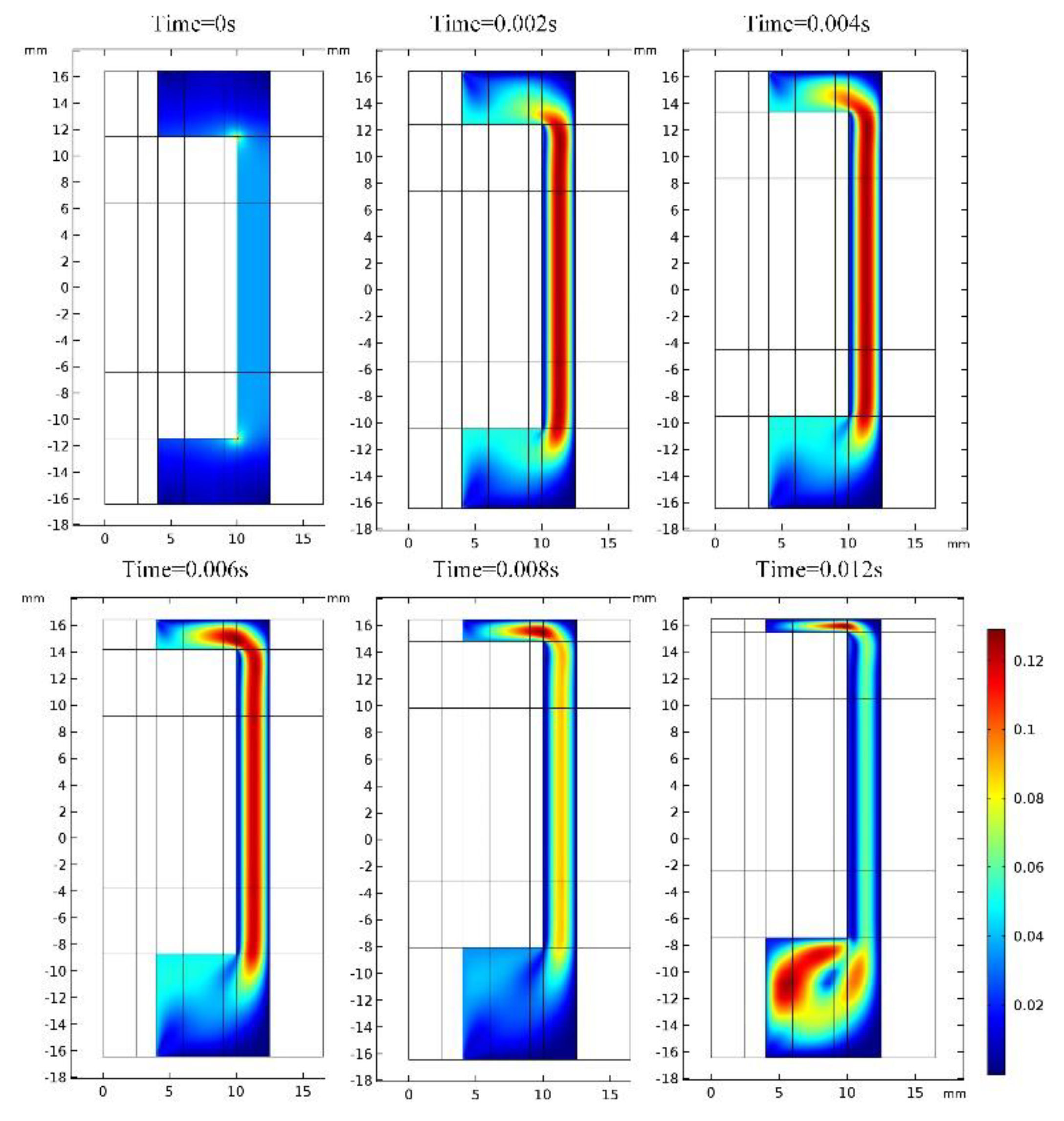
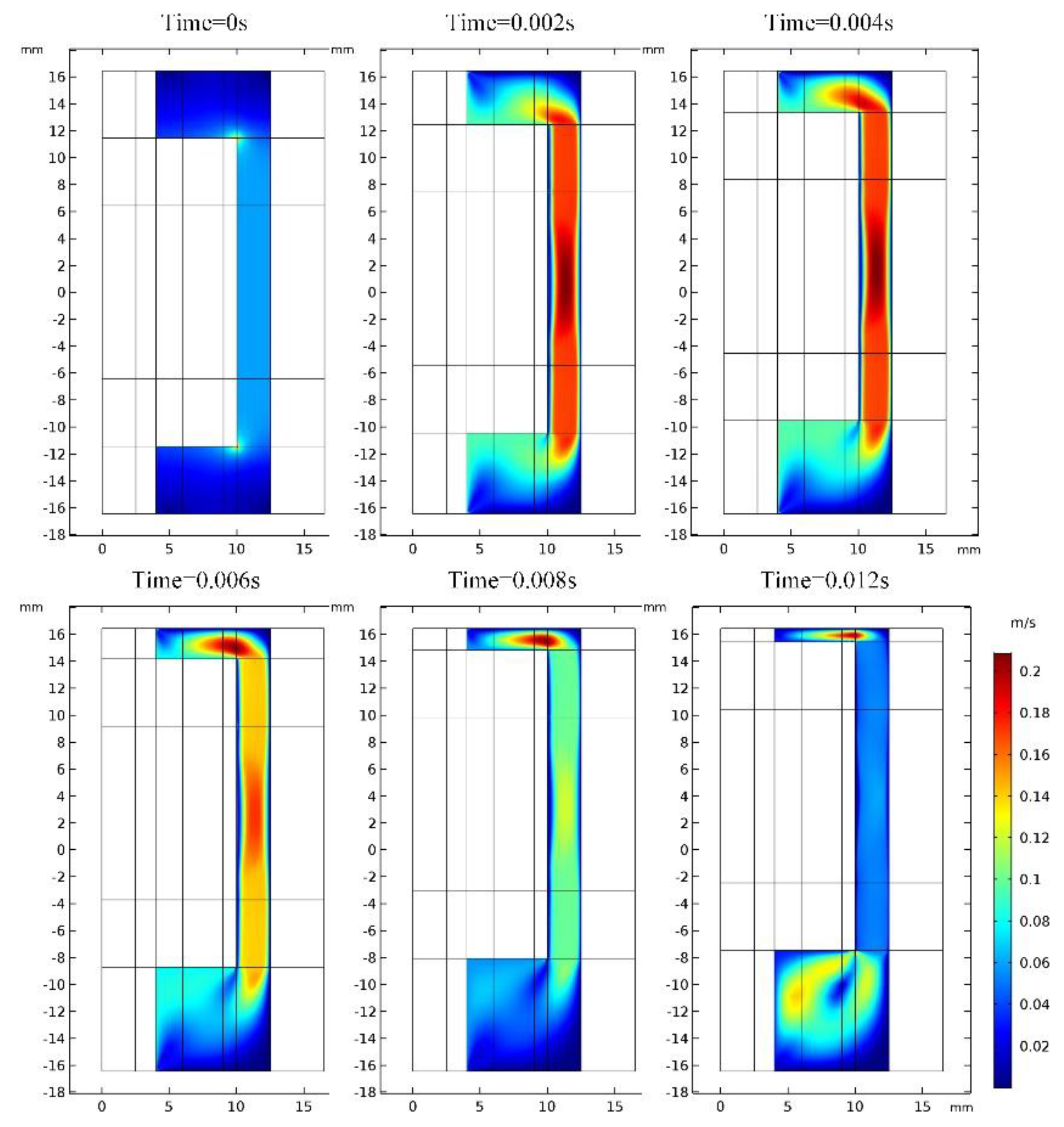
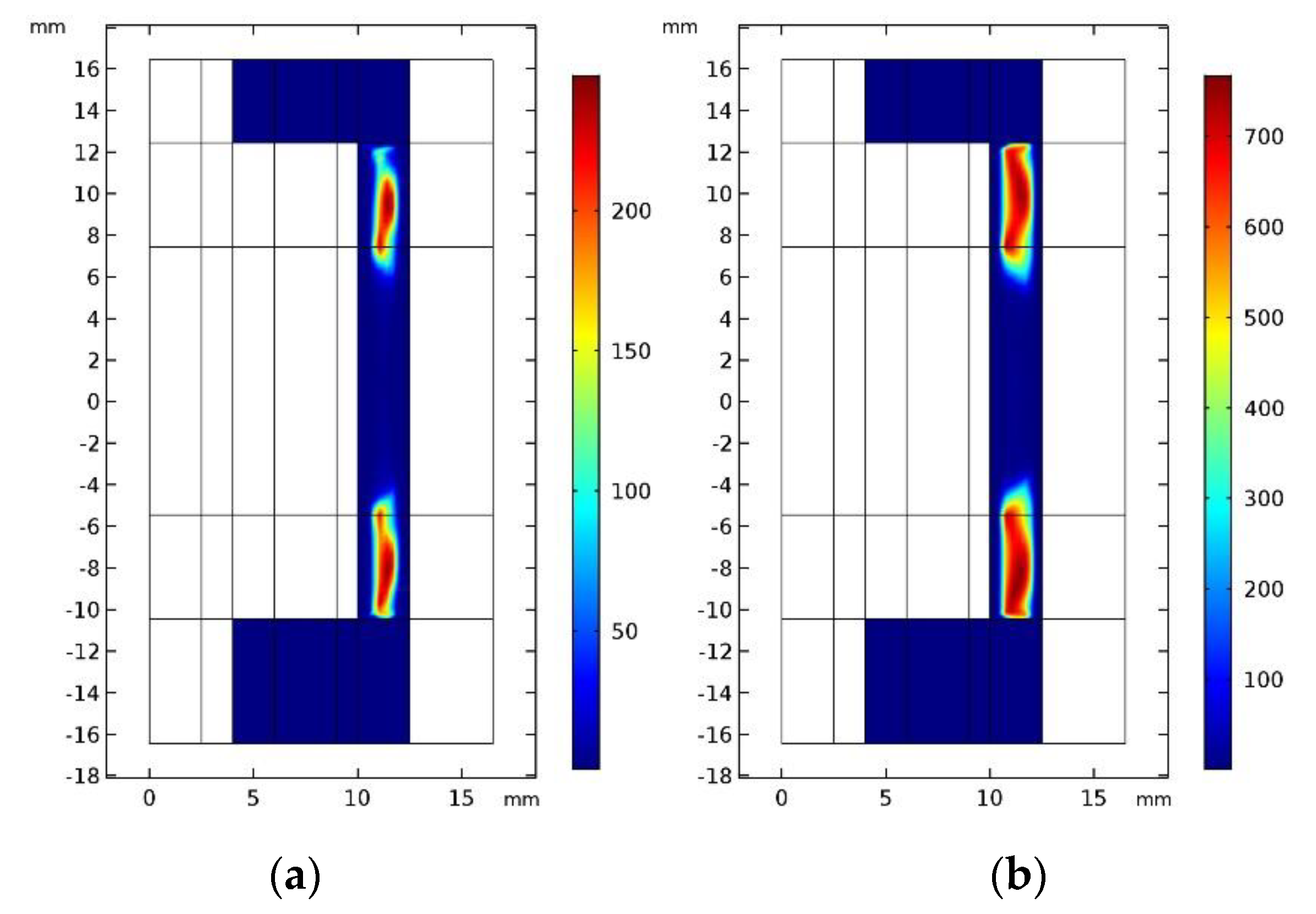
4. Multi-Physics FE Modeling and Simulation of the MR Buffer
5. Validation with Experimental Results
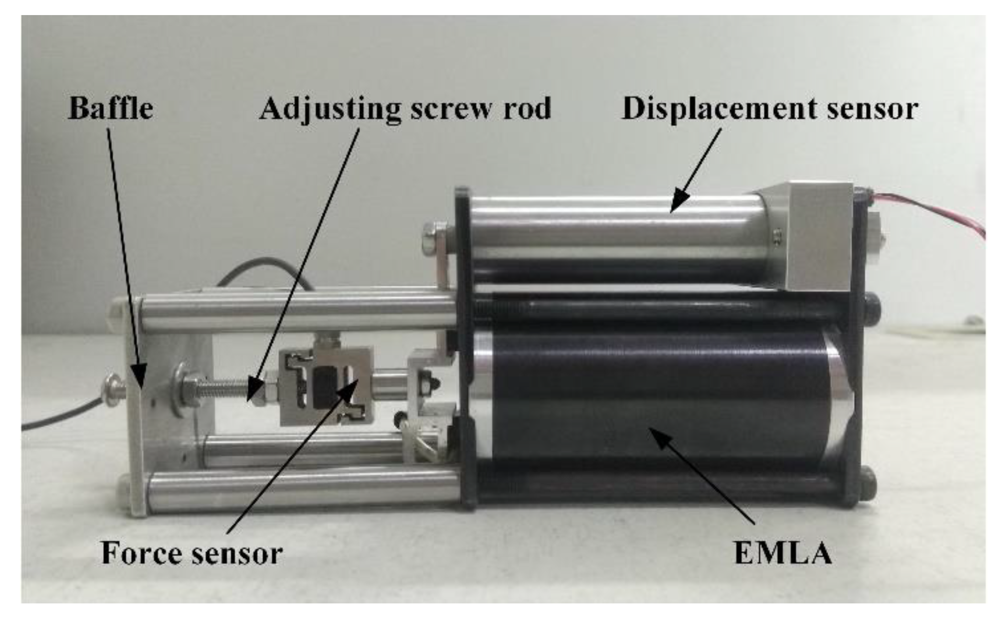
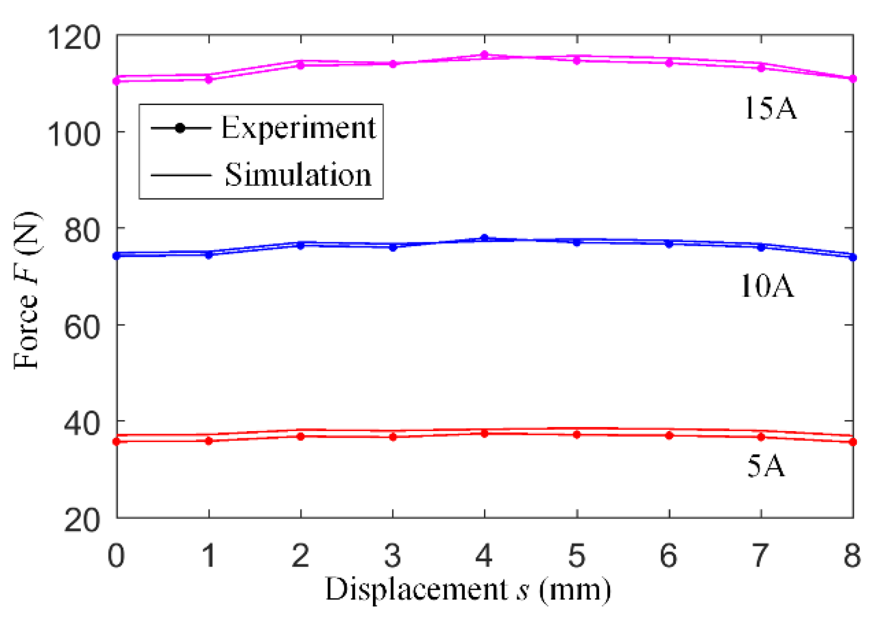
5.1. Electromagnetic Force Characteristic Experiment of the EMLA
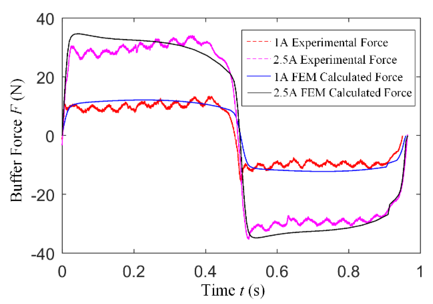
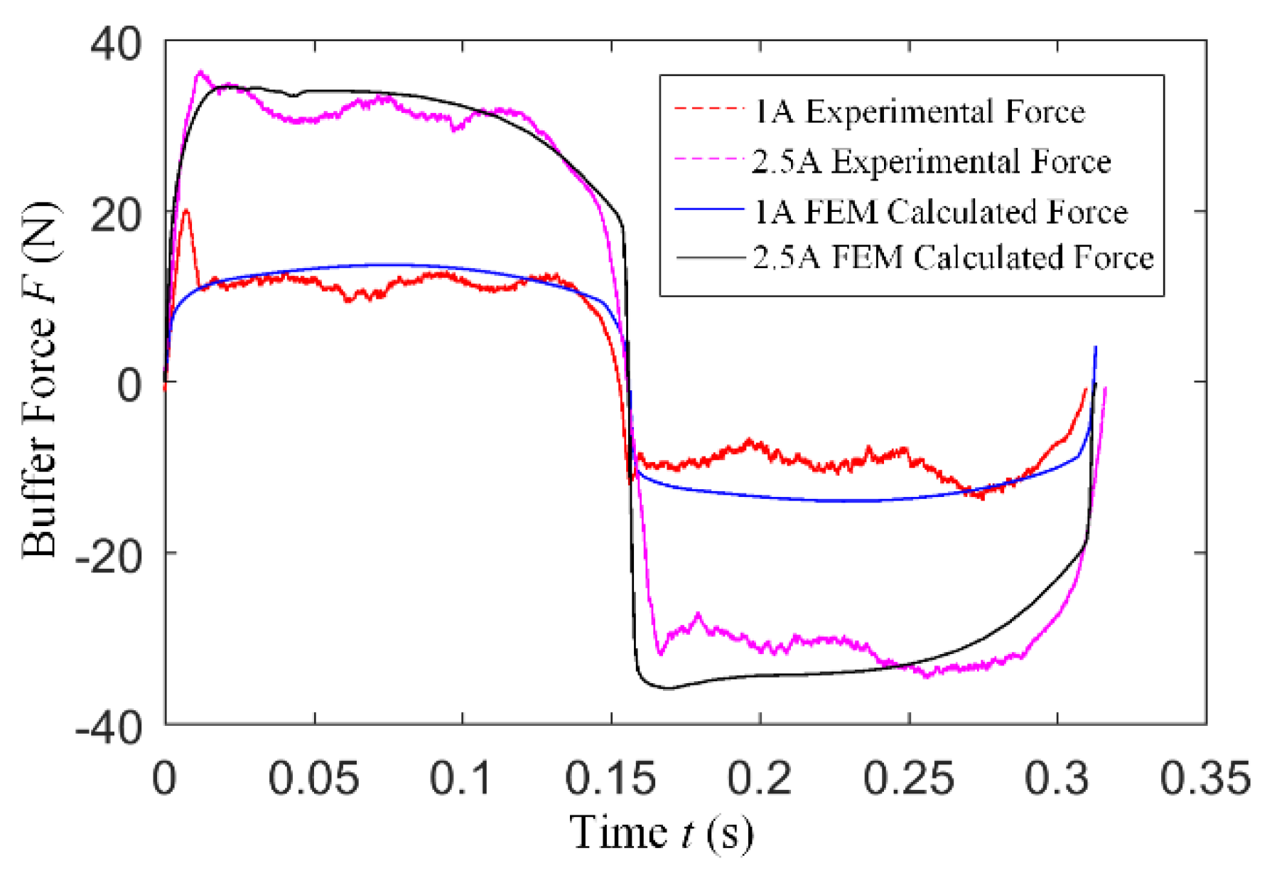
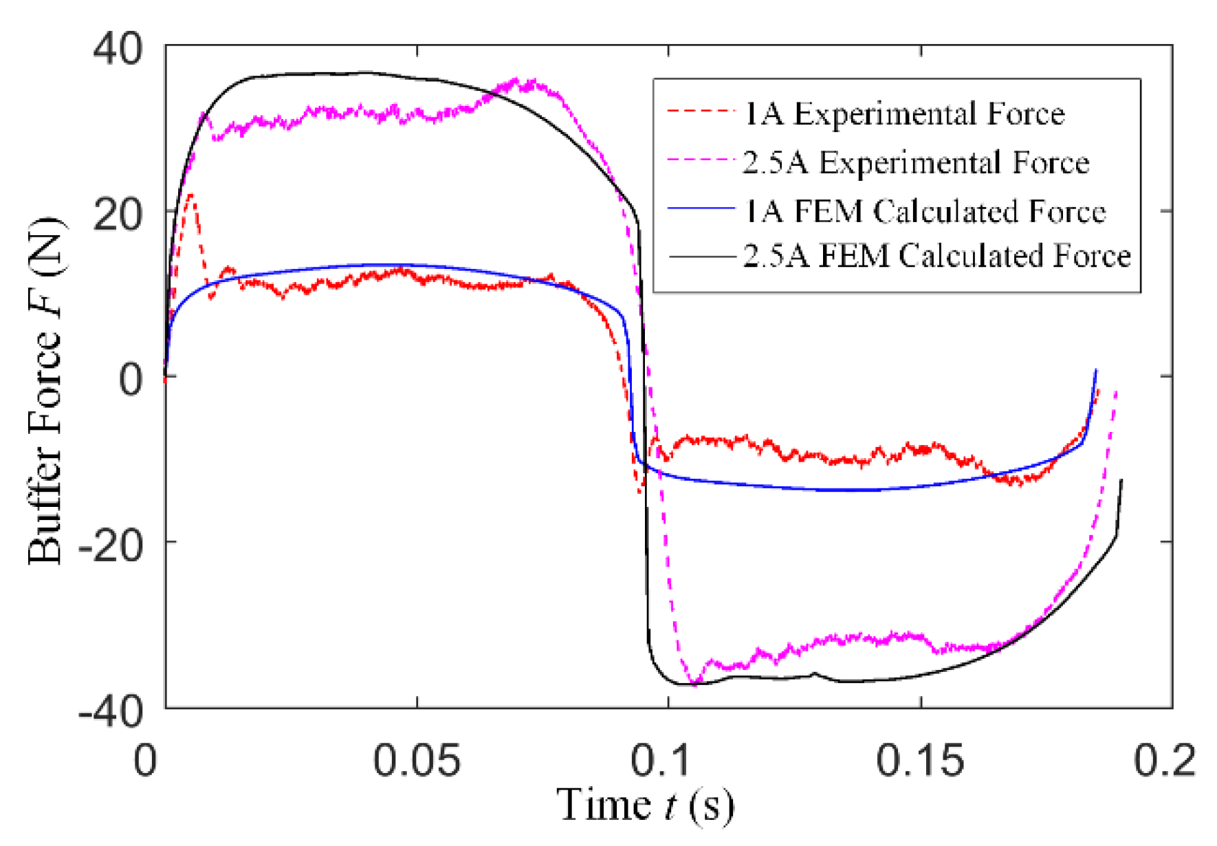
5.2. MR Buffer Force Measurement
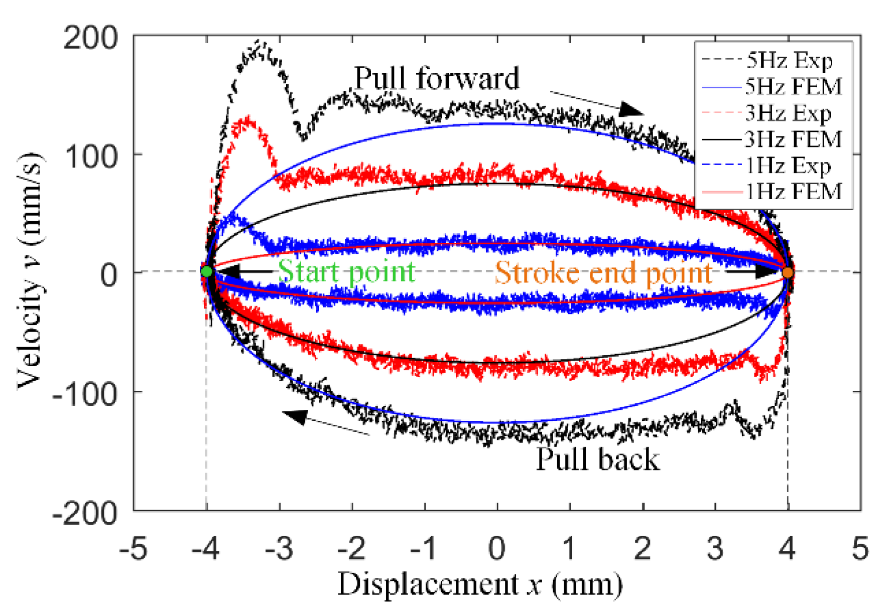
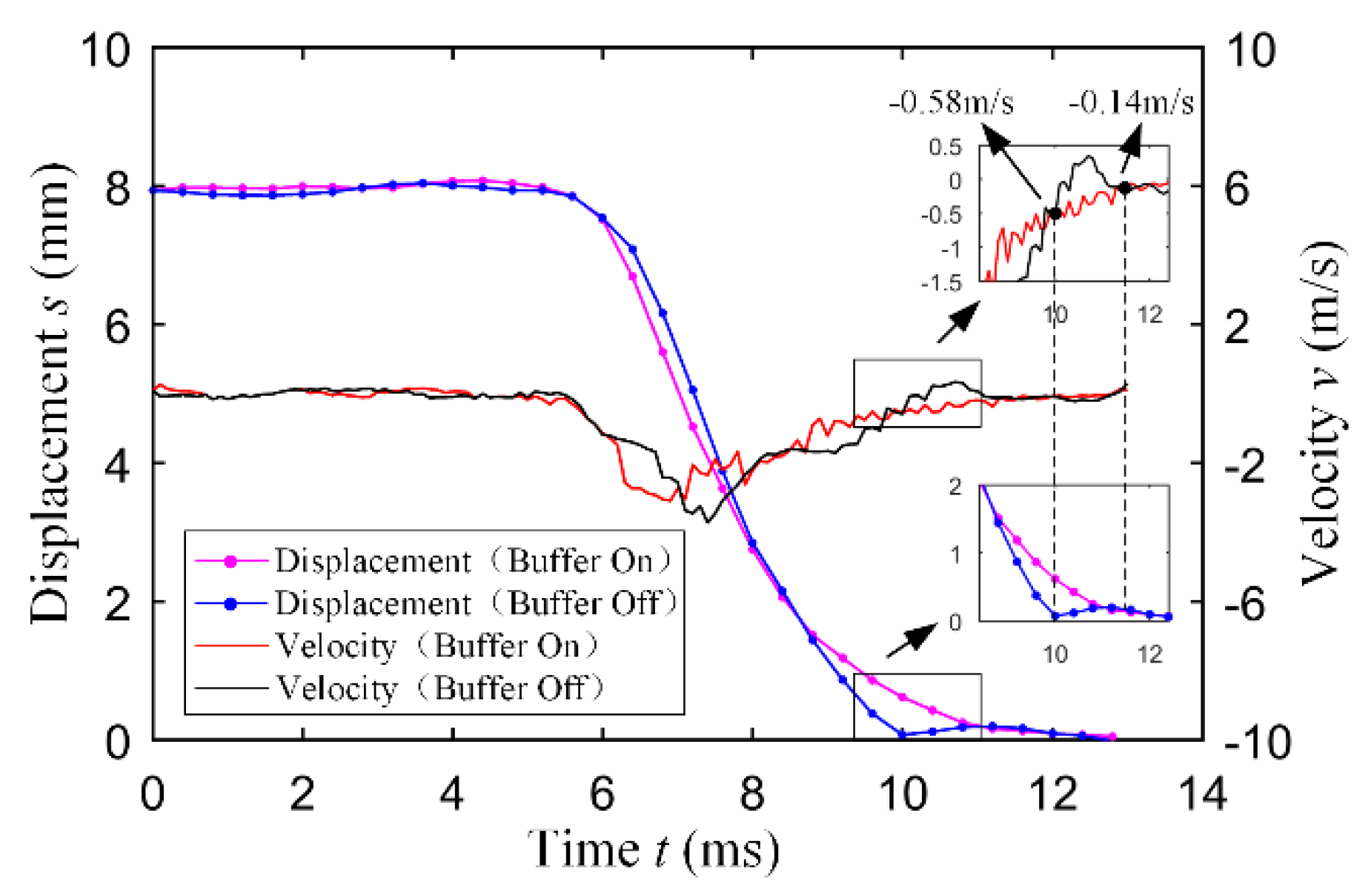
5.3. Seating Performance Experiment
6. Conclusions
Author Contributions
Funding
Conflicts of Interest
References
- Su, W.H.; Zhang, Z.J.; Liu, R.L. Development trend of automotive internal combustion engine technology. China Eng. Sci. 2018, 20, 97–103. [Google Scholar] [CrossRef]
- Leone, T.; Pozar, M. Fuel economy benefit of cylinder deactivation—Sensitivity to vehicle application and operating constraints. SAE Trans. 2001, 110, 2039–2044. [Google Scholar] [CrossRef]
- Millo, F.; Mirzaeian, M.; Luisi, S.; Doria, V.; Stroppiana, A. Engine displacement modularity for enhancing automotive s.i. engines efficiency at part load. Fuel 2016, 180, 645–652. [Google Scholar] [CrossRef]
- Li, R.C.; Zhu, G.G. A real-time pressure wave model for knock prediction and control. Int. J. Engine Res. 2019, 1–15. [Google Scholar] [CrossRef]
- Xu, J.; Chang, S.; Fan, X.; Fan, A. Effects of electromagnetic intake valve train on gasoline engine intake charging. Appl. Therm. Eng. 2016, 96, 708–715. [Google Scholar] [CrossRef]
- Fan, X.; Chang, S.; Liu, L.; Lu, J. Realization and optimization of high compression ratio engine with electromagnetic valve train. Appl. Therm. Eng. 2017, 112, 371–377. [Google Scholar] [CrossRef]
- Fan, X.Y.; Chang, S.Q. Electromagnetic Exhaust Valve Event Optimization for Enhancing Gasoline Engine Performance. MATEC Web Conf. 2017, 95, 15009. [Google Scholar] [CrossRef] [Green Version]
- Li, H. Cam-Free Electro-Hydraulic Variable Valve Mechanism Control of Internal Combustion Engine Based on Model; Beijing Institute of Technology: Beijing, China, 2018. [Google Scholar]
- Yang, J.; Wang, Z.C.; Wang, Y. Design and analysis of electronically controlled hydraulic fully variable valve driving system. J. Hunan Univ. Nat. Sci. Ed. 2017, 2017. [Google Scholar] [CrossRef]
- Chen, F. Simulation and experimental research of hydraulic pressure and intake valve lift on a fully hydraulic variable valve system for a spark-ignition engine. Adv. Mech. Eng. 2018, 10, 1–11. [Google Scholar] [CrossRef]
- Tu, B.; Tian, H.; Wei, H.Q. Research on buffering process of electro hydraulic drive variable gas mechanism. China Mech. Eng. 2016, 27, 2652–2658. [Google Scholar] [CrossRef]
- Paden, B.A.; Snyder, S.T.; Paden, B.E. Modeling and Control of an Electromagnetic Variable Valve Actuation System. IEEE/ASME Trans. Mechatron. 2015, 20, 2654–2665. [Google Scholar] [CrossRef]
- Reinholz, B.; Seethaler, R. Experimental Validation of a Cogging Torque Assisted Valve Actuation System for Internal Combustion Engines. IEEE/ASME Trans. Mechatron. 2016, 21, 453–459. [Google Scholar] [CrossRef]
- Gillella, P.K.; Song, X.; Sun, Z. Time-Varying Internal Model-Based Control of a Camless Engine Valve Actuation System. IEEE Trans. Control Syst. Technol. 2014, 22, 1498–1510. [Google Scholar] [CrossRef]
- Reinholz, B.A.; Reinholz, L.; Seethaler, R.J. Optimal trajectory operation of a cogging torque assisted motor driven valve actuator for internal combustion engines. Mechatronics 2018, 51, 1–7. [Google Scholar] [CrossRef]
- Haus, B.; Aschemann, H.; Mercorelli, P.; Werner, N. Nonlinear modelling and sliding mode control of a piezo-hydraulic valve system. In Proceedings of the 2016 21st International Conference on Methods and Models in Automation and Robotics (MMAR), Miedzyzdroje, Poland, 29 August–1 September 2016; pp. 442–447. [Google Scholar] [CrossRef]
- Samani, R.; Khodadadi, H. A particle swarm optimization approach for sliding mode control of electromechanical valve actuator in camless internal combustion engines. In Proceedings of the IEEE International Conference on Environment & Electrical Engineering & IEEE Industrial & Commercial Power Systems Europe, Milan, Italy, 6–9 June 2017. [Google Scholar] [CrossRef]
- Di Gaeta, A.; Hoyos Velasco, C.I.; Montanaro, U. Cycle-by-Cycle Adaptive Force Compensation for the Soft-Landing Control of an Electro-Mechanical Engine Valve Actuator. Asian J. Control 2014, 17, 1707–1724. [Google Scholar] [CrossRef]
- Bernard, L.; Ferrari, A.; Micelli, D.; Perotto, A.; Rinolfi, R.; Vattaneo, F. Electrohydraulic Valve Control with MultiAir Technology. MTZ Worldwide 2009, 70, 4–10. [Google Scholar] [CrossRef]
- Yang, Y.P.; Liu, J.J.; Ye, D.H. Multi-objective Optimal Design and Soft Landing Control of an Electromagnetic Valve Actuator for a Camless Engine. IEEE/ASME Trans. Mechatron. 2013, 18, 963–972. [Google Scholar] [CrossRef]
- Fan, X.; Chang, S.; Lu, J.; Liu, L.; Yao, S.; Xiao, M. Energy consumption investigation of electromagnetic valve train at gas pressure conditions. Appl. Therm. Eng. 2019, 146, 768–774. [Google Scholar] [CrossRef]
- Zhang, L.L. Research on Engine Valve Load Characteristics and Design of Simulation Loading System; Nanjing University of Science and Technology: Nanjing, China, 2019. [Google Scholar]
- Case, D.; Taheri, B.; Richer, E. Design and Characterization of a Small-Scale Magneto-rheological Damper for Tremor Suppression. IEEE/ASME Trans. Mechatron. 2013, 18, 96–103. [Google Scholar] [CrossRef]
- Sternberg, A.; Zemp, R.; De La Llera, J.C. Multi-physics behavior of a magneto-rheological damper and experimental validation. Eng. Struct. 2014, 69, 194–205. [Google Scholar] [CrossRef]
- Case, D.; Taheri, B.; Richer, E. Dynamical Modeling and Experimental Study of a Small-Scale Magnetorheological Damper. IEEE/ASME Trans. Mechatron. 2014, 19, 1015–1024. [Google Scholar] [CrossRef]


| Parameter | Value |
|---|---|
| Stroke/mm | 8 |
| Diameter/mm | 39 |
| Height/mm | 70 |
| Volume/ | 84 |
| Permanent magnet thickness/mm | 8 |
| Mass of moving parts/g | 114 |
| Parameter | Value |
|---|---|
| Cylinder inner diameter/mm | 25 |
| Piston diameter/mm | 20 |
| Piston rod diameter/mm | 8 |
| Effective length/mm | 10 |
| Annular gap width/mm | 2.5 |
| Cylinder outer diameter/mm | 33 |
| Stroke/mm | 10 |
| Electromagnetic Equations (Maxwell) | Fluid Dynamics Equations (Navier–Stokes) |
|---|---|
 | |
| where: : Electric field, V/m; : Magnetic inductance density, T; : Magnetic field strength, A/m; : Current density, ; : Volumetric charge density, ; : Permittivity of free space = , , : permeability of free space = , . | where: : Velocity field, m/s; : Fluid density, ; : Shear strain rate, 1/s; : Dynamic viscosity, Pa*s; : Fluid zone pressure, Pa; : Yield stress, Pa; : The constant; : Zoom factor, : Volume susceptibility. |
© 2019 by the authors. Licensee MDPI, Basel, Switzerland. This article is an open access article distributed under the terms and conditions of the Creative Commons Attribution (CC BY) license (http://creativecommons.org/licenses/by/4.0/).
Share and Cite
Guo, H.; Liu, L.; Zhu, X.; Chang, S.; Xu, Z. Design of an Electromagnetic Variable Valve Train with a Magnetorheological Buffer. Energies 2019, 12, 3999. https://doi.org/10.3390/en12203999
Guo H, Liu L, Zhu X, Chang S, Xu Z. Design of an Electromagnetic Variable Valve Train with a Magnetorheological Buffer. Energies. 2019; 12(20):3999. https://doi.org/10.3390/en12203999
Chicago/Turabian StyleGuo, He, Liang Liu, Xiangbin Zhu, Siqin Chang, and Zhaoping Xu. 2019. "Design of an Electromagnetic Variable Valve Train with a Magnetorheological Buffer" Energies 12, no. 20: 3999. https://doi.org/10.3390/en12203999