Article

Fault Ride-Through Enhancement of Grid Supporting Inverter-Based Microgrid Using Delayed Signal Cancellation Algorithm Secondary Control

by
Elutunji Buraimoh
1,*,
Innocent E. Davidson
1 and
Fernando Martinez-Rodrigo
2
1
Department of Electrical Power Engineering, Durban University of Technology, Durban 4001, South Africa
2
Department of Electronics Technology, University of Valladolid, Valladolid 47014, Spain
*
Author to whom correspondence should be addressed.
Energies 2019, 12(20), 3994; https://doi.org/10.3390/en12203994
Submission received: 29 August 2019 / Revised: 12 October 2019 / Accepted: 14 October 2019 / Published: 21 October 2019

Abstract

:
The growing level of grid-connected renewable energy sources in the form of microgrids has made it highly imperative for grid-connected microgrids to contribute to the overall system stability. Consequently, secondary services which include the fault ride-through (FRT) capability are expected to be possessed characteristics by inverter-based microgrids. This enhances the stable operation of the main grid and sustained microgrid grid interconnection during grid faults in conformity with the emerging national grid codes. This paper proposes an effective FRT secondary control strategy to coordinate power injection during balanced and unbalanced fault conditions. This complements the primary control to form a two-layer hierarchical control structure in the microgrids. The primary level is comprised of voltage/power and current inner loops fed by a droop control. The droop control coordinates grid power-sharing amongst the voltage source inverters. When a fault occurs, the participating inverters operate to support the grid voltage, by injecting supplementary reactive power based on their droop gains. Similarly, under unbalanced voltage condition due to asymmetrical faults in the grid, the proposed secondary control ensures the positive sequence component compensation and negative and zero sequence components clearance using a delayed signal cancellation (DSC) algorithm and power electronic switched series impedance placed in-between the point of common coupling (PCC) and the main grid. While ensuring that FRT ancillary service is rendered to the main utility, the strategy proposed ensures relatively interrupted quality power is supplied to the microgrid load. Consequently, this strategy ensures the microgrid ride-through the voltage sag and supports the grid utility voltage during the period of the main utility grid fault. Results of the study are presented and discussed.

1. Introduction

The introduction of renewable energy sources (RESs) based distributed generations (DGs) also known as distributed energy resources (DERs) into the modern electric power systems has raised significant challenges such as bidirectional power flow in the distribution system, stochastic generation nature of RESs, and distinctive fault current properties [1]. Microgrids (MG) are low-voltage mini-grids and their concept is projected years back to aggregate RESs, energy storage systems (ESS,) and loads to efficiently manage and control the DGs [2,3,4]. Consequently, MGs have served as a prospective platform where RESs are integrated into the modern-day distribution system with operational flexibility and controllability in either grid-dependent or autonomous modes [5]. In microgrids, controllable voltage source inverters (VSI), are commonly used to interface various RESs such as photovoltaic (PV), wind, batteries, fuel-cells, and micro-turbines to enhance the control flexibility and ensure high quality of electric power in systems [6,7,8,9].
The system frequency, voltage, and power flow control for autonomous MG are determined by renewable energy sources. However, in grid-connected modes, the main grid imposes most of the supply standards [9]. In stand-alone operation, voltage and frequency are regulated using control schemes with multi-loop [8,10]. These control systems are usually implemented in any of these reference frames; synchronous direct-quadrature-zero coordinates, stationary alpha-beta-gamma coordinates, and natural three-phase coordinates [8,11]. In a distributed generation, inverter interfaces are typically connected in parallel [12] with appropriate power-sharing among them. Numerous control strategies have been proposed to achieve a suitable power (active and reactive) sharing, such as: average current control [13], master–slave control [14,15], and circular-chain-control [16]. A decentralized control technique frequently employed in the instance of inverters operated in parallel to avoid circulating currents is droop technique [17]. Droop control is extensively used in microgrids and relies on localized information to achieve decentralized control. This makes it a more appropriate power-sharing technique compared to various high bandwidth communication network-based techniques [6,18].
The inverter interface isolates the DGs and the wider main grid electrically; and nevertheless serves as an economical link to allow electrical energy transfer and ancillary services at the interface [19]. Several challenges are inherent owing to the sensitivity of the bidirectional flow of power between the microgrid and host utility grid [5]. In the event of voltage disturbances occasioned by faults in the host grid, studies infer the instant switching from grid-connected to islanded mode [20]. The total grid impedance up to the fault and the voltage at the point of fault occurrence have been identified in fault analysis as major factors affecting electrical faults in the grid [21,22]. The energy-generating units are expected to disconnect from the grid at the instance of voltage sags and reconnect just at the moment that the fault or disturbance is cleared. Therefore, MGs were not expected to provide additional services including low voltage or fault ride-through (LVRT/FRT) supports. Conversely, due to the growing penetration of the grid-interactive and high power capacity MGs, it is expected that they deliver a substantial quantity of power to the host grid when operational in grid synchronous mode. During fault or voltage sag, this will alleviate the potential instability by ensuring the active power delivery to local microgrid loads and reactive power support to the host grid. Avoiding the disconnection of high capacity MGs during grid fault or any disturbance forestalls potential network instabilities [
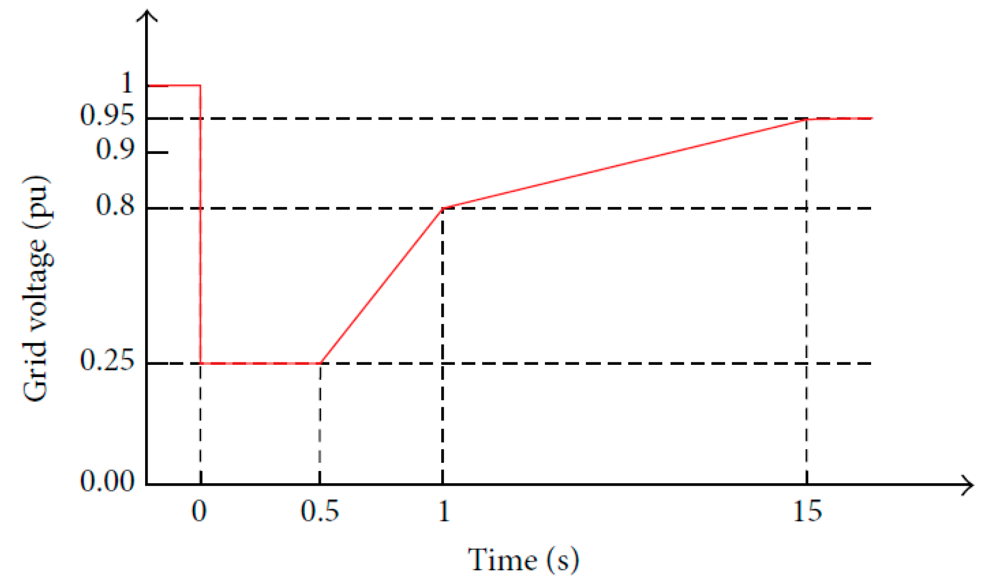
23]. As a result, some developed countries have amended their respective grid codes to make provisions for rising RES capacity. Spain, Germany, and Denmark are among the foremost countries in 2004, 2006, and 2008 that already issued the FRT/LVRT requirements for DERs connected to the grid [24,25]. Spanish code requirement is displayed in Figure 1 accordingly. Even though these requirements are projected for the high-voltage grid, they are however valid for low-voltage grid due to similar concepts [18].
The power quality (PQ) of a grid-connected DG, as well as that of load connected, is degraded during the period of disturbance such as a fault in the host grid [27]. Supporting PQ schemes—such as static synchronous compensators (STATCOMs), unified power quality conditioner (UPQCs), and dynamic voltage restorers (DVRs)—have played tremendous roles in FRT capability enhancement of the of DER systems [28,29,30]. Similarly, several innovative FRT control strategies and schemes have been proposed in [26,31,32]. Zamani et al. [33] recommend a scheme for the control of an inverter interfaced RES for performance enhancement of the host grid during disturbances and faults. In Kou and Wei [32], certain considerations on various grid code requirements for MGs interconnection and operation were made, which recommends LVRT capabilities for MGs and provision of additional services under faults. By these recommendations, grid-connected MG is required to ride-through balanced and unbalanced sags in grid voltage as expressed in FRT voltage profile. However, interruption followed by a transition into autonomous operation is only permitted when fault persists [20]. Fault current limiters (FCLs) are utilized in minimizing the contribution to the fault current level of the DGs to improve FRT [34]. References [35,36] suggested different types and modified superconducting FCL; flux-coupling-type, resistive type to enhance the microgrids, wind turbines, solar photovoltaic and other DGs FRT capabilities. The FCL potential to enhance FRT is well established in works of literature [37,38]. FCL is positioned between a microgrid and main network and as such, overall FRT is achieved for all of the microgrid DERs [39]. A supplementary controller for voltage is suggested in [40] for the FRT control of inverters based DGs. This controller is expected to be superimposed with numerous available voltage control schemes with minimum adjustments. These modifications, therefore, do not necessarily need to alter the initial configuration of these existing controllers. Towards realizing the numerous microgrid control and operation requirements, a hierarchical control has been proposed in [41,42] with fundamental control goals which include voltage control, local power allocation among distributed energy units, frequency regulation and power control (active and reactive) under synchronization with host grid [6]. A rapid fault detection system plays a crucial role in enhancing the effects of these several strategies.
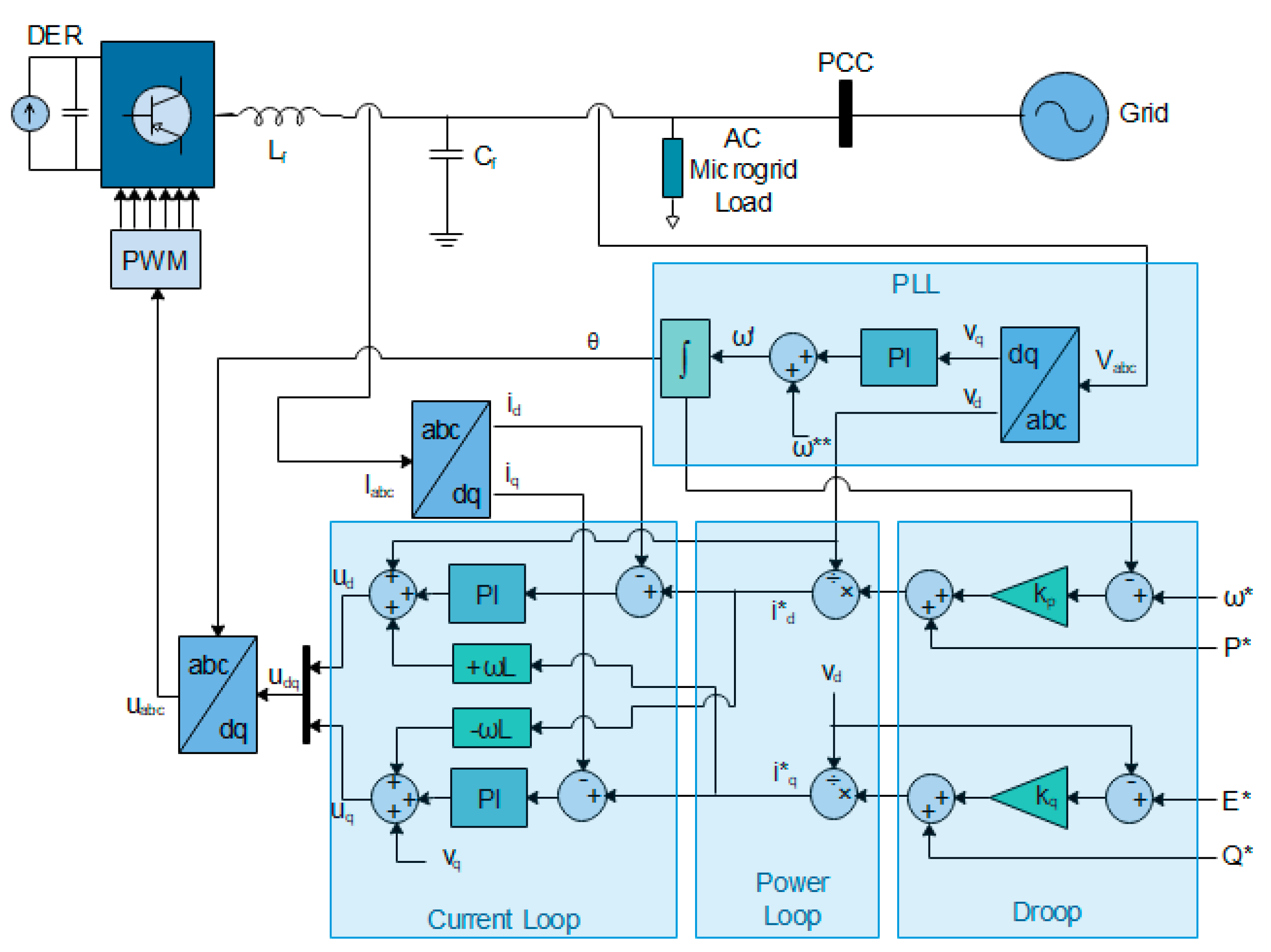
To meet the anticipated FRT requirements, control schemes and topologies for the grid-supporting MG need to be developed. This work aims at developing a secondary control scheme for the FRT/LVRT enhancement of a droop controlled grid supporting inverter-microgrids using delayed signal cancellation and stationary reference frame control for the reactive power injection and fault current limitation. To satisfy numerous requisites of operation and control in a microgrid, the secondary LVRT control stipulates set-points for the primary control that consists of the droop, power and current loops. These two levels form a hierarchical control structure. The strategy requires no mode switching and enables the inverter-interfaced MG to ride through faults or transient disturbances on the host utility grid. The need for resynchronization of microgrid with the main grid as proposed in seamless transition method [43,44,45,46] after fault clearance is completely unnecessary and shedding of local loads is avoided. In a grid supporting system, the active and reactive power is controlled to meet local load requirement and the surplus MG power is simultaneously delivered to the main grid. Active power and reactive power are controlled through frequency regulation and voltage regulation respectively, such that local power-sharing among constituent inverters is not compromised in any way.
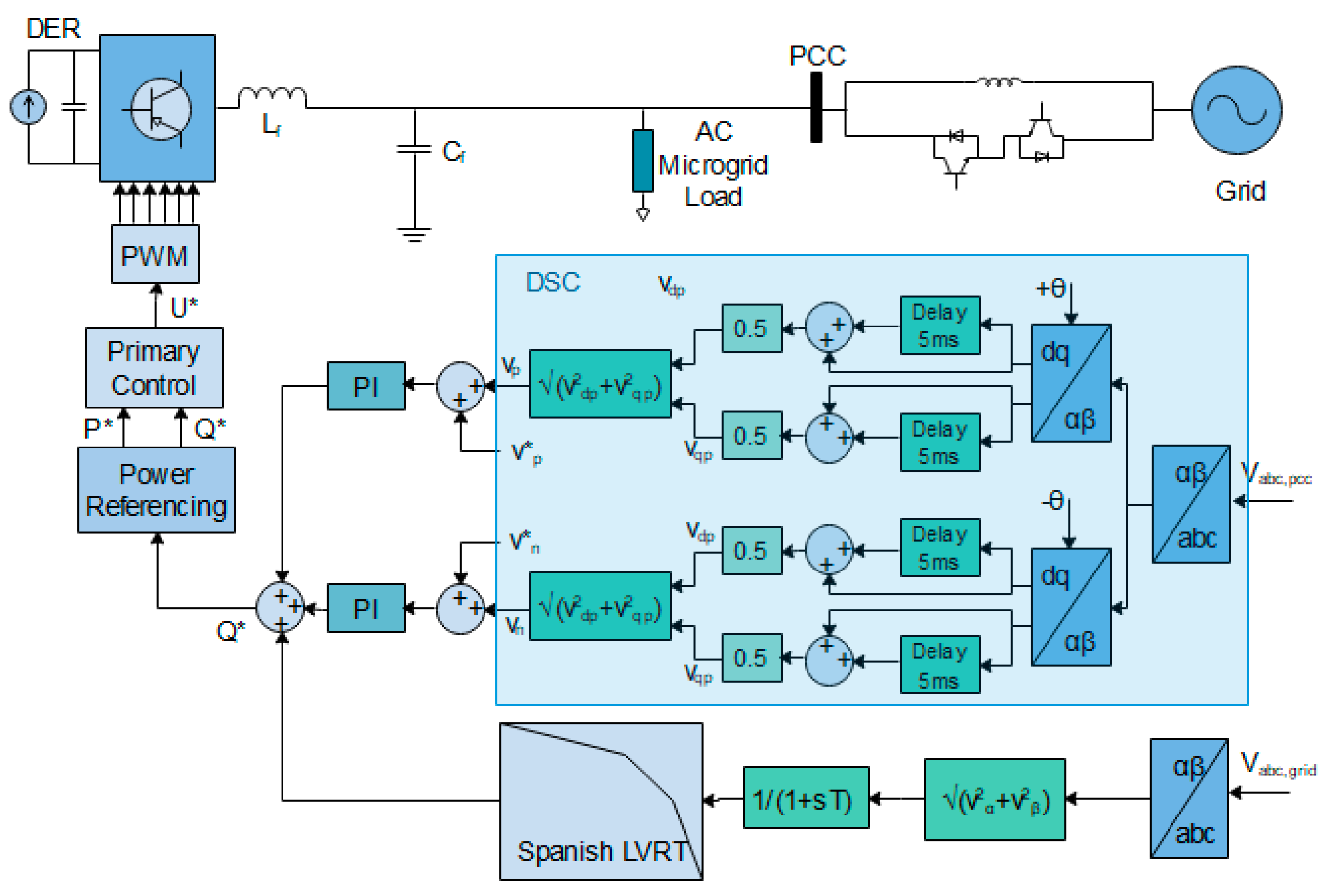
Acceptable power quality for the local loads during fault duration is ensured with the inclusion of a properly sized anti-parallel IGBT-diode switched inductance. It is noteworthy that as a result of high R/X ratio in low voltage distribution feeder line, injecting reactive power under faults may not substantially contribute to the recovery of voltage. Hence this work has been able to deploy a properly sized anti-parallel IGBT-diode switched inductance at the PCC of the MG with the grid to reduce R/X ratio and effectively support the voltage under grid disturbance. This provides protection and alleviates the effects of fault especially on the local sensitive loads of the microgrid. Consequently, a direct theoretical framework has been provided for the determination of the value of this switched inductance. Furthermore, this arrangement counteracts the effect of grid disturbances by limiting transient overcurrent throughout grid faults. This is enhanced by the introduction of a secondary control block that regulates the active power and reactive power exchange between the host grid and the microgrid in conformity with the stipulated utility grid standard.
To ensure the efficient and prompt responsiveness, a fault detection procedure built on a delayed signal cancellation (DSC) algorithm is implemented to detect the fault instantly in less than 0.05 s. The DSC algorithms apply the concept of PLL and therefore enhanced with fast detection of the positive sequence and negative sequences [47,48,49]. In [40], an LVRT strategy is proposed which implements the wavelet-based fault detection technique as given in [50,51]. The voltage disturbance detection method based on wavelet transform can detect the faults within 3.12 ms. The DSC technique is efficient for faster convergence and detects faults within 0.1515 ms under various unbalanced voltage conditions has been validated in several works of literature [52,53,54,
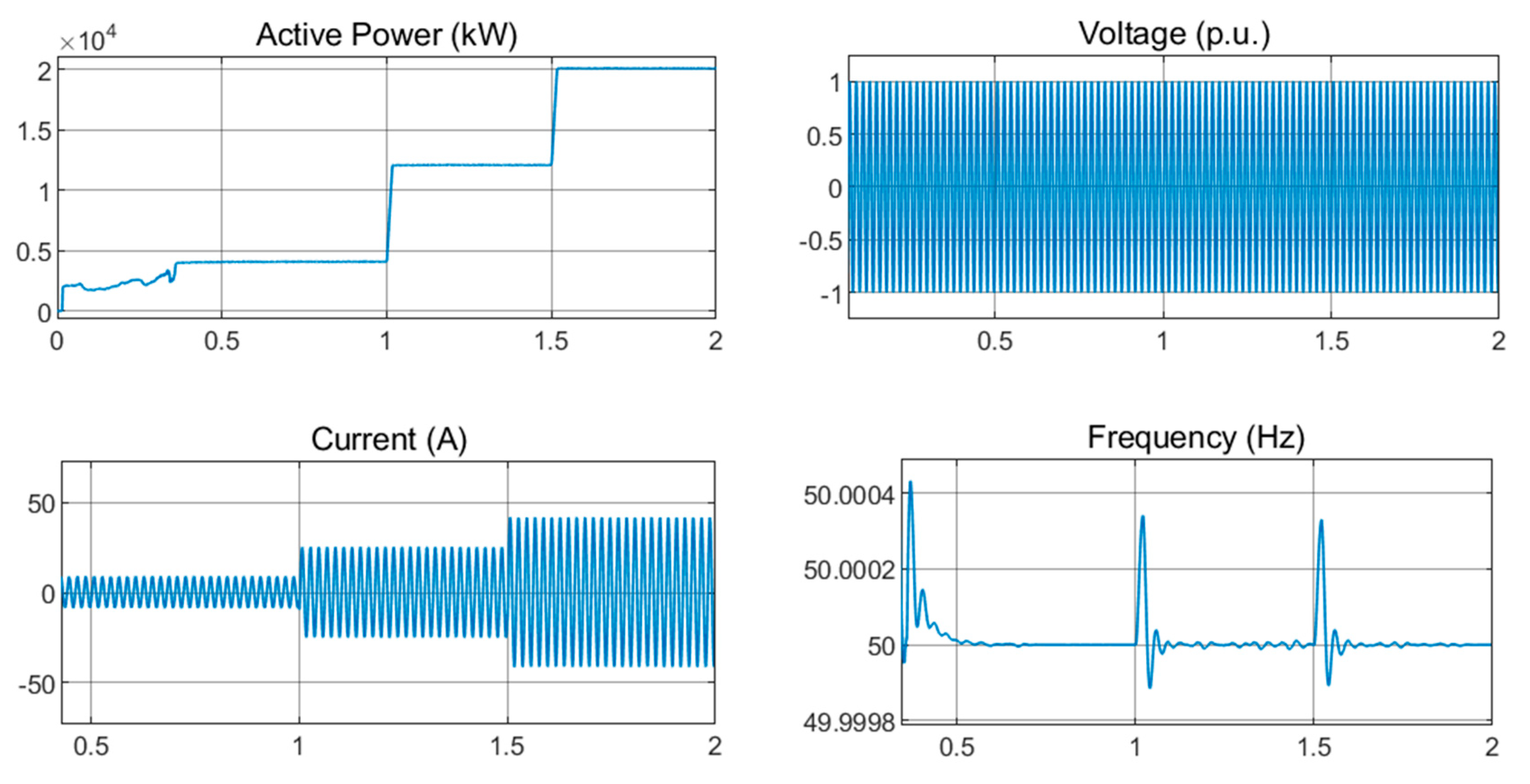
55] using simulations and experiments. DSC determines the fault interval at which active and reactive power references are adjusted appropriately. Lastly, DSC is used in giving adequate information for the control of the PCC voltage and this ensures quality power delivery to the microgrid loads irrespective of the transients on the main grid. The simulation results reveal the performance and effectiveness of the proposed scheme in enhancing LVRT/FRT requirements of Spanish code.
The rest of this paper is organized thus: 
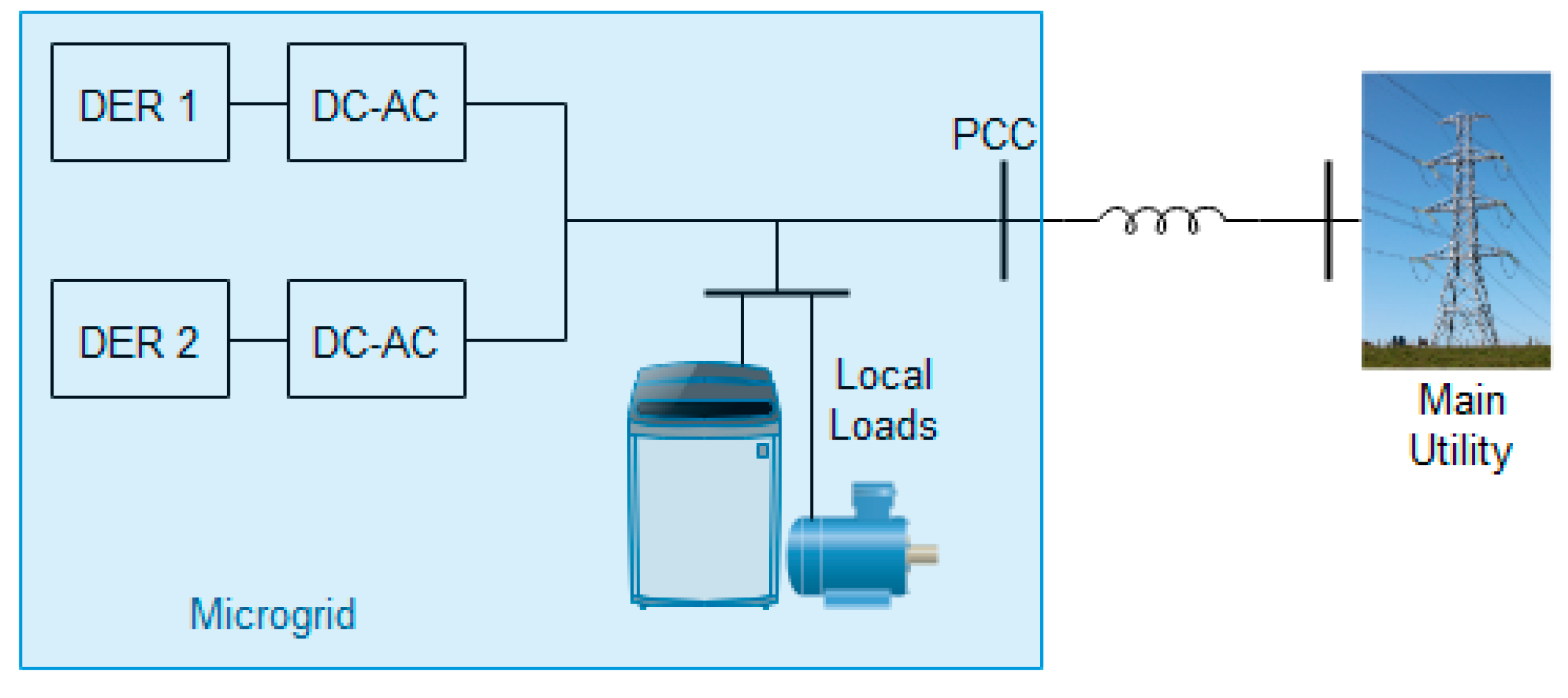
Section 2 presents the modelling of a grid supporting MG system whose aim is to actively partake in grid voltage and frequency regulations via the control of active power and reactive power supplied to the AC grid; Section 3 describes the proposed secondary FRT control of voltage with the description of DSC; 
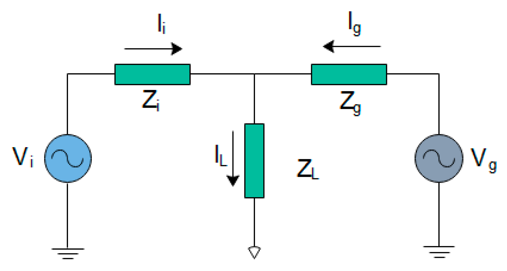
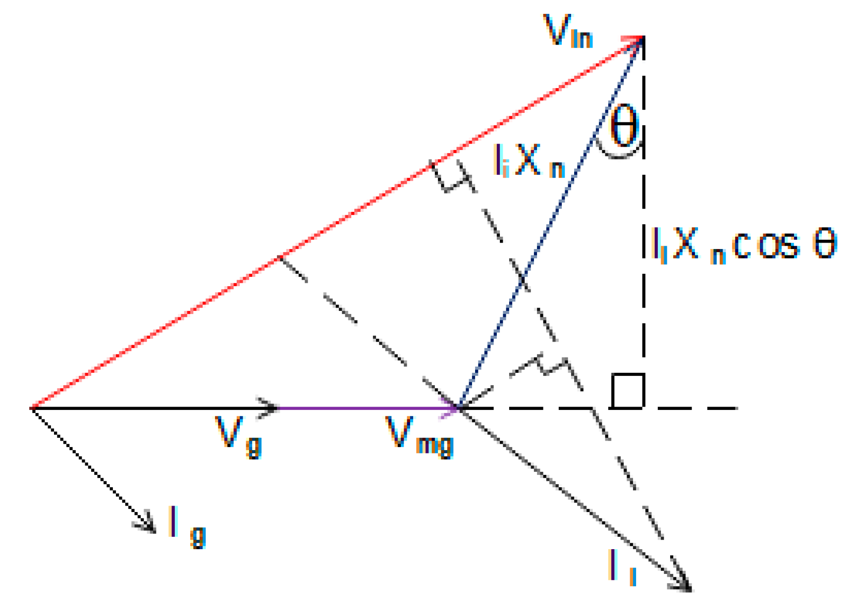
Section 4 discusses the power flow in a grid support system and presents the how to determine the value of IGBT-diode switched reactor; and Section 5 shows the detailed results of simulation of the proposed strategies under symmetrical disturbance and asymmetrical disturbance on the grid.

2. Grid Supporting Microgrid Modeling

The grid-supporting inverter fits the control and hardware topology most typical of three-phase VSI utilized in interfacing numerous DERs. It is intended to fill a variety of roles and can export power at any specified power factor, when connected to weak grids, stiff grids and to a low-inertia RES dominated microgrid. Figure 2 is a grid-interactive inverter system whose output is connected to a stiff host grid. Its model can be derived in a synchronously rotating reference frame by using the PLL phase angle. The innermost loop controls the filter inductor current, following current references and removing cross-coupled terms caused by the reference frame transformation. The outer loop specifies the current references corresponding to required or specified active power and reactive power references. The VSI and the LC filter constitute the power processing unit. The output is interfaced to the grid via the LC filters where the L is the coupling inductor with C as the shunt capacitor. The entire system reference is the common reference frame where the dynamics of each constituent generating unit are transformed using the angular frequency ω. Subsequently, the decoupling of the active and reactive power is done through Park transformation (abc-dq).

2.1. Output LC Filter

The two most widely used passive filters are the LC and LCL filters. LC filters are deployed in a situation where a local load exists between the inverter and the host grid while the latter is employed where there is nonexistence of local loads [56]. The LC filter attenuates the output voltage ripple and limits the high-frequency ripple current of power electronic switches [57]. The LC filter circuit equations are derived from the synchronous reference frame. Figure 2 shows filter inductance Lf and shunt capacitance Cf. The grid impedance or transformer leakage inductance or both serve as coupling inductor [58]. The LC filter arrangement depicted is used for the grid-connected inverter with local load in between. This work focuses on the parallel operation of inverter-based microgrid with a local load while in grid supporting mode. Consequently, the LC filter is used in inverter output considering the presence grid impedance between the microgrid and the host grid. The cut-off frequency fc of the LC filter is given by
f c = 1 2 π LC
The voltage/power loop and current control loop are designed in such a way to eliminate high frequencies as a result of disturbances by providing adequate damping for the output LC filter [9].

2.2. Grid Synchronization

The AC grid voltage parameters; voltage magnitude, grid frequency, and phase angle of an inverter-based MG are key to accurate and dynamic control of active power and reactive power injected. Therefore, a precise estimation of these aforementioned parameters has a significant effect on the inverter general performance. Furthermore, continuous parameter sampling and AC grid condition monitoring are required to dynamically decide the appropriate and optimal mode of operation. The inverter-based microgrid synchronization using PLL ensures appropriate response during normal and abnormal AC main grid condition [10]. The phase angle and frequency of the main grid is closely tracked by the synchronous reference frame PLL using Equation (2).
T a b c d q = [ cos ( ω t ) cos ( ω t 2 π 3 ) cos ( ω t + 2 π 3 ) sin ( ω t ) sin ( ω t 2 π 3 ) sin ( ω t + 2 π 3 ) ]
Equation (2) transforms a three-phase instantaneous voltage from the natural abc reference frame to a rotating synchronous dq reference frame by Park (abc-dq) transformation. In the dq reference frame, the Equation (3) shows an angular position, which is regulated via the feedback loop driving the voltage quadrature component vq to zero.
θ = ω = ( ω * + ( k p + k i s ) × v q )
By the synchronization arrangement, ω’ is estimated frequency of the AC grid while the rated reference frequency ω* signifies PLL’s feed-forward which enhances the phase estimation θ’ dynamics and this is achieved by integrating ω’.

2.3. Primary Control

Different microgrids with a wide-ranging array of operation and control objectives; grid-forming, grid-feeding, grid-supporting, require sets of well-coordinated and designed control schemes to guarantee effectual operation especially in the dynamic state [10]. The power-sharing, voltage/power, and current controllers locally regulate the output variables of the inverter with high-performance bandwidth to ensure prompt response time in a dynamic state. In the hierarchical control architecture, these three different loops all constitute primary control level that ensures microgrid stability.
The focal objective of the primary level of control is controlling the active power and reactive power interaction and export between DERs and host AC grid as voltage sources being controlled by the current [59]. The positive sequence control loops regulate the active power contributed by every constituent inverter interfaced DER. This active power supply is maximized under a symmetrical grid situation subject to the available active power potential in case of RES-based DG system. However, under asymmetrical grid voltage situations, the negative and zero sequence control loops regulate the reactive power delivery. DGs supply the obtainable active power from the maximum power tracking system in normal grid conditions. A percentage of total active power generated, together with the entire reactive power, is supplied to meet microgrid load demand, while the remaining percentage of the active power generated is directly provided to the main utility grid consumption.

2.3.1. Droop-Based Power Control

The effective distribution and allocation of required power among the inverter-based DERs of a given microgrid is implemented by a droop control scheme. Droop emulates frequency and voltage regulation of a typical synchronous generator at the inverter output. Several power sharing control schemes—such as average current-sharing, master–slave, and droop—have been significantly employed to control parallel-connected inverter-based DERs. In microgrids, parallel-connection of inverters are known to improve the overall performance and reliability even with the failure of a constituent parallel inverter [60,61,62]. Propitiously, droop controls have been generally acknowledged as the most effective power-sharing scheme due to flexibility and nonexistence of significant communication networks between parallel-connected inverters [17,63]. Furthermore, various techniques have also been proposed in the literature to improve the performance of droop and grid-connected inverters at high RES penetration [64,65]. The injected active power by a particular constituent inverter into a reference bus is largely dependent on α which denotes angle of power. However, reactive power is significantly influenced by the voltage amplitude [17]. The droop characteristics equations of both frequency and voltage as they relate to the active power and reactive power respectively are written as
ω = ω * k p ( P * P m ) E = E * k q ( Q * Q m )
where kp and kq are the coefficients of the frequency and voltage droops of the inverter, respectively. Similarly, P* and Q* are active and reactive power references, respectively. Furthermore, the measured output of active power and reactive power are signified by Pm and Qm, respectively. Also, ω* signifies the set-point frequency while E* is the rated set-point amplitude of the voltage. Hence, voltage magnitude and frequency are set by the coefficients of the voltage and frequency droops specified for the active power and reactive power. In Equation (4), droop control shares every load change among inverters by adjusting the frequency by the specified coefficient of frequency-active power droop. In a grid-supporting VSI, the measured active power and reactive power Pm and Qm at any point in time are computed using the measured output three-phase current and voltage transformed to the equivalent direct-quadrature components as depicted in Equation (5) at the fundamental frequency of ω*
P m = 3 2 ( v d i d + v q i q ) Q m = 3 2 ( v d i q v q i d )
With the frequency droop gain, the frequency is determined and integrated for setting the phase. Therefore, the dynamic features and inertia characteristics of conventional generators are mimicked with incorporated negative feedback. Similarly, with a voltage droop gain, the voltage magnitude is determined which is equivalent to a d-axis output voltage reference. In other words, the control ensures the magnitude reference of the output voltage is in line with the d-axis voltage component of the reference frame while zero voltage q-axis component reference is maintained [9].

2.3.2. Power/Voltage Loop Control

Both loops for voltage/power and current regulation are used to set the final reference for the voltage used as the input of the pulse width modulation (PWM) of the VSI. The PLL stipulates the reference voltages (v*d and v*q) of direct-quadrature axes based on its synchronization with the grid. Consequently, the voltage/power loop control uses the v*d and v*q to generates the references currents (i*d and i*q) for the direct-quadrature axes components using the measured active power and reactive power as given in the Equations (4) and (5) and shown in Figure 2. This control can also be realized with a PI control scheme such that the controller output is given by
i d * = ( k p v + k i v s ) [ v d * v d v d p ] i d * = ( k p v + k i v s ) [ v d * v q v d p ]
where kIV and kPV are the integral gain and proportional gain of the voltage PI control respectively. The vdp is the drop in voltage due to the grid or virtual impedance.
However, in a grid supporting VSI that operates in the role of a typical current source, the voltage control loop is regarded as power control loop such that the references, i*d and i*q, generated are computed using the output of the droop power-sharing Pm and Qm such that
i d * = 2 3 P m v d * i q * = 2 3 Q m v q *
In the absence of any disturbance or fault at the AC side of the VSI, this control loop regulates the active and reactive power to ensure the transfer of power from DC to AC side of the VSI. Under this balanced voltage condition, the voltage vd is constant and the active power is regulated by adjusting the current id. Similarly, the reactive power regulated through the current iq control. Therefore, the active power and reactive power transferred to the AC side is determined by making Pm and Qm the subjects of the formulas in terms of stationary quantities in Equation (7) [66].

2.3.3. Current Loop Control

Loops for voltage/power and current regulation simultaneously play the roles of setting the final reference for the voltage used as the input of the PWM of the VSI. Furthermore, according to the current references, i*d and i*q, generated by the loop of voltage control, the loop of current control generates reference voltage (ud and uq) of direct-quadrature-axes for the PWM. This control is realized using a PI controller such that the controller output is expressed as
u d = ( k p i + k i i s ) [ i d * i d ] + v d + ( ω L ) × i q * u q = ( k p i + k i i s ) [ i q * i q ] + v q ( ω L ) × i d *
where kii and kpi denote integral and proportional gains of the current control loop respectively. The direct-quadrature axes components vd and vq of the voltage signify the feed-forward quantities while +(ωL)i*q and −(ωL)i*d signify the cross decoupled quantities. The feed-forward and cross decoupled quantities are employed to accomplish independent dq axis current controls. Lastly, L in the cross-decoupled quantities is the output filter inductor.

3. Proposed LVRT/FRT Scheme

Faults are usually unbalanced and the grid codes are less strict in asymmetrical fault cases (phase to ground and line to line) unlike strict regulations imposed under the symmetrical (three-phase) disturbance. However, certain limitations are imposed which include the prohibition of the grid absorption of both active power and reactive power in the event of fault as stipulated by the Spanish P.O.12.3 document [67,68]. Consequently, the unbalance in the grid can be promptly eliminated alongside current limiting by inhibiting grid active power absorption and supporting grid voltage recovery by contributing an appropriate reactive current. The microgrid topology used for the purpose of this paper is shown in Figure 3.

3.1. Secondary Voltage Control

This study uses Spanish grid code guidelines [26,69] in developing the FRT/LVRT secondary control. These documents released by the government stipulates that grid-connected DGs should ride-through at least 0.2 pu grid voltage drop lasting for 500 milliseconds. However, these DER are permitted to disconnect from the grid when the voltage drops versus the time are outside the FRT curve. Moreover, DERs are demanded to inject a stipulated reactive power quantity defined by the reactive power support capability to support voltage sag as depicted in Figure 4. However, an insignificant amount of reactive power support is expected during voltage sag that falls above 90%. In essence, the Spanish grid code specifies a certain amount of reactive current/power (per unit) injection based on the percentage voltage drop. Equation (9) clearly explains the aforementioned side by side with Figure 5.
Q r e f = { ( 93 70 6 7 V g V N ) Q N , V g 0.5 V N ( 57 100 6 V g V N ) Q N , 0.9 V N V g > 0.5 V N , ( 1 1 5 V g V N ) Q N , V g > 0.9 V N
where VN signifies the rated grid voltage at nominal value, reactive power QN corresponds to the rated reactive current of the inverter and reactive power reference Qref corresponds to the required reactive current that will be injected. of the microgrid. The reference required signal of reactive current is obtained in the same degree with the depth of voltage sag on the grid, through the proposed secondary control loop. Once this voltage falls below 0.9 of the nominal value, the secondary control scheme will instantly commence reactive current/power support as shown in the Equation (9). The injection of reactive power/current is systematically regulated to ensure the restoration of voltage above 0.9 of the nominal value, instead of exactly 0.9 VN. The immediate detection of faults in systems is crucial in enhancing the overall reliability, productivity, and safety, hence the Clarke transformation of the measured grid voltage is done using Equation (9) and shown in Figure 4. The magnitude is conditioned using a first-order low pass filter and subsequently monitored. The essence of this is to prevent and unnecessary activation of the anti-parallel IGBT-diode switching arrangement for the inductance. With this, fault occurrence and clearance are detected with 0.05 s as shown in the results.

3.2. DSC Algorithm for Unbalance Detection and PCC Voltage

To avoid exceeding the limit, the PCC voltage magnitude control is put in place to buffer and avoid exceeding the limit of grid code prescript and acceptable range (0.9–1.1 pu). The values of its symmetrical components are obtained to implement an effective unbalanced grid voltage compensation. Towards actualizing the aforementioned, delayed signal cancellation (DSC) as depicted in Figure 5, is deployed to detect the presence of symmetrical components and obtain their values accordingly.
The algorithm for DSC is centered on the three-phase voltage measurement and subsequent decomposition into their commensurate symmetrical components [66]. Primarily, the voltages measured in phase are denoted in stationary reference frame using the Clarke (abc-αβ) transformation.
[ v α v β ] = [ 1 0 0 0 3 3 3 3 ] [ v a v b v c ]
In line with the resultant stationary reference frame above, two opposite rotations are executed using the phasor measured angle of the host grid voltage (θ and −θ). This angle θ matches the same provided at the output of the phase-locked loop.
The positive component implies
[ v d p v q p ] = [ cos θ sin θ sin θ cos θ ] [ v α v β ]
The negative component implies
[ v d n v q n ] = [ cos θ sin θ sin θ cos θ ] [ v α v β ]
The values obtained for vqp and vqn are subsequently kept for half a period in two independent data buffers. Lastly, the positive component and negative component final samples are obtained and immediately kept in the two buffers at a time equivalent to half a period. The components and their additions are expressed in Equations (13)–(16):
The positive component implies
v d p ( k ) = 1 2 [ v d p ( k ) + j v d p ( k f s 4 f g ) ]
v q p ( k ) = 1 2 [ v q p ( k ) + j v q p ( k f s 4 f g ) ]
The negative component implies
v d n ( k ) = 1 2 [ v d n ( k ) + j v d n ( k f s 4 f g ) ]
v q n ( k ) = 1 2 [ v q n ( k ) + j v q n ( k f s 4 f g ) ]
The second term samples in Equations (13)–(16) are equivalent to the first term components and however, they are shifted a fourth of period and this shifting is depicted by j multiple of the second terms. Once the sequence components of the PCC voltage are obtained in direct-quadrature coordinates at the instance of grid fault using Equations (13)–(16), the two PCC voltage-independent control system operates to restore to normal sequence references. Positive sequence control aims to bring back the PCC voltage positive sequence level to its rated value. Hence, the error, in this case, is utilized in regulating the reactive power Qp injected into the grid while considering power electronic switch thresholds. Similarly, the PCC voltage negative sequence control restores quadrature component to the zero references of normal condition. This balances and buffers the further PCC voltage unbalance introduced through reactive power injection into the grid.
The microgrid voltage at the local load point of connection with the PCC is therefore controlled by the control scheme using the DSC to independently adjust both positive component and negative component in conformity with their respective sequence references. Thus, the microgrid voltage for the DERs and local sensitive loads relatively enhanced regardless of the voltage sag experienced in the main grid. Therefore, active power is uninterruptedly delivered to the microgrid sensitive load while delivering ancillary voltage support service to the main grid. The independent controls of the voltage at the point of common coupling of the microgrid to the main grid is expressed in the Equation (17).
Q p = ( k p p + k i p s ) [ v p * v d p 2 + v q p 2 ] Q n = ( k p n + k i n s ) [ v n * v d n 2 + v q n 2 ]
The aggregate reactive power injection from the microgrid through the PCC to the utility grid for ride-through and reactive power support implies
Δ Q = Q p + Q n + Q r e q

4. Power Flow and Switched Reactor

4.1. Voltage Source Inverter and Grid Interactive Power Flow

In inverter grid supporting mode, there is power interaction with host grid which involves power exchange. The equivalent power flow diagram between the inverter-based microgrid and the host grid is shown in Figure 6, where vi signifies the VSI voltage and vg represents the grid voltage. Similarly, the inherent impedances of the inverter and its filter circuit are lumped together as Zi while the grid impedance is represented as Zg. The load current and impedance are signified by IL and ZL. These aforementioned impedances are typically inductive owing to the significant output inductance of the VSI. Nevertheless, this inverter impedance can be greatly influenced by the type of control strategy employed [70], and grid impedance is highly resistive in low-voltage distribution feeder lines [71]. Similarly, the impedance (resistance and inductive reactance) of the grid is significantly present and taken into consideration in microgrids located at a long distance away far from the host grid. Consequently, this work put into consideration the line impedance of the grid. In line with the stipulation of the grid codes, only reactive current is injected all through the period of voltage sag. Consequently, the resulting compensating voltage is relatively in phase with the grid voltage.

4.2. Switched Inductance: Sizing and Switching

A microgrid is to ensure required uninterrupted supply of quality power to the local sensitive loads besides fulfilling FRT requirement of reactive power support in the event of disturbance on the main grid. In this work, this is ensured by ascertaining that all the sections in the microgrid are supplied with a constant voltage at a regular frequency. The proposed scheme in Figure 5 shows the implementation of this requirement through an additional reactive power injection. The VSI injects a significantly high amount of reactive power in supporting the utility grid and sustain microgrid load voltages since the grid impedance is usually low [72]. However, the aforementioned secondary control based LVRT schemes are significantly limited in voltage sag compensation. To tackle this problem, a PCC voltage moderation scheme based on PI control using the DSC positive and negative is introduced. Furthermore, under a strong (stiff) main grid connection, independent control of the point of common coupling voltage and by extension microgrid voltage is not sufficient for good power quality since the host grid imposes the voltage. Thus, control strategies may not be able to effectively restore the network voltage especially at the PCC [73,74]. Hence, a switched inductance is inserted in series at the PCC to the main network during a voltage disturbance to increase the network impedance to independently regulate the microgrid voltage irrespective of the host grid condition. Thus, sustaining the PCC voltage at the rated magnitude.
The appropriate sizing and switching of this inductance ensure sustained microgrid voltage irrespective of a host grid disturbance. The inductance size is estimated in relation to the voltage sag in the worst-case scenario which must be compensated at PCC. It also depends on the expected current flow through the inductance under voltage sag. The balance between microgrid generated power (active and reactive) and the local load consumption determines the current flow (magnitude and phase angle) through the inductance during grid disturbance. In the proposed strategy of this work, during the grid fault, the total microgrid generated active power is commensurate with the rated local load capacity to limit the amplitude of the current flow into the main grid. However, excess active power may still be supplied to the main grid due to varying load demand and this affects the inductance size. To estimate required value for the series inductance, the load demand is assumed to be zero and the rated load power is assumed generated and supplied to the host grid. The phasor diagram of this estimation is presented in Figure 7, where Vg represents the phase voltage of the host grid, Vmg represents phase voltage within the microgrid. Similarly, Xn signifies needed switched inductive reactance while In signifies current flow across Xn. The inverter voltage is therefore given by
V i n 2 = ( I i X n cos θ ) 2 + ( V m g + I i X n sin θ ) 2
Consequently, the value of the series inductance is determined by solving the quadratic equation generated by making the Xn the subject of the formula in Equation (18). It is therefore given as
X n 2 + [ 2 V m g sin θ I i ] X n + [ V m g 2 V i n 2 I i 2 ] = 0
The inverter current Ii is in phase with the current flowing through the switched inductance Xn, hence angle θ is calculated from
θ = cos 1 [ P r a t e d S max ] = cos 1 [ I d I d 2 + I q 2 ]
In a typical low voltage distribution lines, the resistive component (R) is high [10,75] and therefore the R/X ratio is considerably reduced with series incorporation of a comparatively sizable inductance. Hence, the addition of an extra inductance may cause a depreciation in voltage regulation, particularly within the microgrid. Therefore, the inductance is only inserted during a main grid voltage disturbance by the operation of the anti-parallel IGBT-diode switches in Figure 5. A fault condition or disturbance leading to voltage sag at the grid is detected by the fault detection. This simultaneously generates alternating pulses for the switching on of the anti-parallel switches and uses the Clark transformation in detecting fault using a low pass filter. Then the switching pulses are off once a fault is detected and the voltage sag is observed in 0.0001515 s. Thus, the inductive reactance is introduced swiftly devoid of any adverse influence on the effectiveness of the FRT control strategy.

4.3. Active Power Referencing and Fault Current Limiting

In a grid supporting inverter without a local load, the active power set-point is zero under fault for effective limiting the active current magnitude and jack up the reactive current within the apparent power limit. This by extension limits the fault current observed at the PCC. However, under normal operating conditions, maximum power point tracking (MPPT) output imposes the active power reference instantaneously at a 100 per cent power factor. The presence of disturbance within the host grid thereby leading to voltage sag or swell causes the reactive power reference to be evaluated based on
Q n e w * = Q * + Δ Q
where Q* represents the reference of the reactive power of the inverter before voltage sag and ΔQ already specified in Equation (17). By the control strategy proposed, the reactive power needed is commensurate to the depth of percentage voltage drop. Consequently, the active power and the reactive power generated from the DER and injected through inverter must be realistic such that it conforms to the complex power equation as well as preventing inverter overloading. The grid codes stipulate grid reactive power support by all connected generating units however, it is also important inverter ensure a continuous supply of active power to the microgrid sensitive load irrespective of grid conditions. Therefore, due to the reactive power (current) injection, the active power (current) injection is limited. Thus, the reference P* for the inverter active power is computed using the Equations (23).
P * = { ( S max * ) 2 ( Q n e w * ) 2 i f ( P * ) 2 + ( Q n e w * ) 2 > S r a t e d P * e l s e
where P* signifies the active power reference of the inverter before voltage sag and Srated represents the maximum tolerance in which the active reference limit triggers and Smax represents the inverter maximum complex power specified by the manufacturer. The maximum complex power confines the references of active power and reactive power within its value as shown in Equation (23).

5. Results and Discussions

The effectiveness of this FRT approach proposed is investigated on a grid-connected microgrid system consisting of two DERs and local load, as depicted in Figure 2. Various types of faults are simulated on the main grid and are switched on at time t = 1.3 s and assumed to be automatically cleared at t = 1.8 s. The common types of power system faults are the triple-phase to ground (L-L-L-G), double line to ground (L-L-G), single line to ground (L-G), and line-to-line faults (L-L). These faults lead to different degrees and types of voltage sag within the grid and at the PCC of grid supporting microgrids. In simulating the grid faults, the fault resistances of 0.7 Ω, 0.5 Ω, and 0.3 Ω are used to produce 70%, 60%, and 50% voltage sags at constant ground resistance of 0.001 Ω and snubber resistance of 1000 Ω. The simulations were performed in MATLAB/Simulink/SimPower software. Two inverter-based distributed energy resources DER 1 and DER 2 are used to form microgrid energy sources. DERs 1 and 2 feed a local microgrid load of 10 kW with a power factor of 0.90. The excess power generated in the microgrid by these DERs is distributed into the main utility grid while the DERs also participate in the frequency and voltage regulations through their respective droops in the primary control. Installed at the PCC is a step-up transformer of 0.400/11 kV phase to phase rms through which the excess generation is supplied to the host grid. The other parameters used in the simulations are shown in Table 1, Table 2, Table 3 and Table 4.
The DER inverters are modeled in detailed states and selection of control parameters done by SimScape closed-loop auto-tuner which computes a linearized approximation of the nonlinear dynamic system models. Figure 8 below gives the responses of the model while putting into consideration the dynamics of the inner power/voltage control loop, current control loop, and detailed model parameters. The power set points of the modelled grid-supporting systems are changed in three steps at times 1.0 s and 1.5 s. These values are 4 kVA, 12 kVA, and 20 kVA at unity power factor to validate the response of inverter and portray typical grid supporting system. The corresponding dynamic responses in active power, voltage, current, and frequency are shown to validate the detailed model used in the simulation. The strategy implemented in the simulations can be deployed for low voltage ride-through of a solar PV based grid-connected microgrids and can be used for the interface FRT control of large scale grid-connected battery energy storage systems.

5.1. Symmetrical Fault

Figure 9 shows the pulses generated in each of the phases for the control of the IGBT-diode switches. This shows that the fault is detected within 0.0001515 s in all phases for the activation of the FRT scheme and of course the switching of the inductor. These pulses activate the switching operation of the IGBT-diode-based switch and properly change the operating mode of the switching control system at fault inception and fault clearing instants.
For balanced voltage sag, the main grid fault; triple-phase to ground is used to simulate voltage sag of 50% in evaluating the proposed strategy. The extent of the voltage sag on the main grid is shown in Figure 10, which prompts a corresponding rise in the current amplitude.
The prompt current amplitude limitation is provided by the secondary power reference embedded in the FRT scheme of the secondary control in each of the DER as shown the Figure 5 and depicted by the Equations (9) and (23). The active and reactive current references are changed instantaneously at fault inception. Similarly, these references are properly restored immediately fault condition is over with appropriate tuning of the kp and ki gains of the proportional–integral controllers. Thus, Figure 10 reveals a smooth transition from pre-fault to fault and subsequently, from fault to post-fault condition. Therefore, the output current of DERs’ LC filter is appropriately limited as shown in Figure 10. Consequently, the 50% voltage sag percentage observed at the PCC to the grid is improved to 93.32% in the microgrid.
The voltage sag on the main utility is detected at the PCC in at 0.0001515 s which is less than half of the first cycle of fault occurrence. This implies that the fault is detected in 1.3001515 s as shown in the positive half cycle and 1.300 on dot in the negative half cycle. Consequently, the FRT scheme fault mode operation is activated with simultaneous switching of the IGBT-diode switched reactor in series with all the phases for balanced transient conditions and series with only the affected phase in unbalanced conditions. The grid voltages for all the balanced conditions of voltage sag resulting in 50% voltage sag are shown in Figure 10. The implementation of the FRT schemes for DERs of the microgrid ensured that the microgrid voltage is compensated for the effective running of the microgrid irrespective of the main grid transient condition. The voltage in the microgrid is improved to 93.32% under 50% sags measured at the PCC.
The fault current limiting ability of this secondary control with an appropriate selection of the gains of the PI controller, the DER 1 and DER 2 contribute to the main grid voltage reactive power support based on their kVA ratings. Figure 11 presents the output current waveforms of the DERs on 50% voltage sag at the PCC. The DER output currents are properly limited and no significant distortion is observed in the signals of DER output voltage and current. Thus, it is clear that the inverter currents are appropriately limited in the first cycle after fault inception at 1.3 s, as shown in Figure 10 and Figure 11. The delay of 0.00016 after the fault for the activation of the proposed control is short and insignificant. However, overcurrent produced between 1.30000 and 1.30016 s cannot damage the inverter semiconductor switches. Furthermore, grid faults technically appear across the filter capacitor and the transient current overshoot at fault inception vanishes almost instantaneously and is therefore ignored. It must be noted that the current overshoot at the instance of transient disturbance is completely attenuated whenever the VSI based DER is tied to an electrically weak grid far from the inverter installation.
Following EN50160 standard, the THD of output voltage waveforms of any generating unit must not exceed 8% [76]. Consequently, the THDs (before, during and after fault clearance for various fault types causing 70%, 60%, and 50% voltage sags) of DER voltage signals and output current waveforms are revealed in Table 5. The THD is measured using fast Fourier transformation analysis in MATLAB. The excellent signal quality as signified in the low THDs of the DER voltages and output current is an indication of efficient performance of the FRT scheme put in place in this work. The microgrid voltages as observed demonstrate high-quality waveforms, output DER voltage, and current. The voltage harmonics are relatively negligible with reference to the current harmonics. The low THD recorded indicates great power factor, high efficiency, and small peak current. This reveals the effectiveness of this proposed FRT strategy at the secondary control and conformity with the IEC 61000-3-2 standard [77].
In compliance with the grid codes, the FRT control arrangements ensure the delivery of a commensurate reactive power in supporting grid voltage sag, thereby effecting DERs ride through of disturbances. Consequently, the changeover from grid synchronous to the islanded mode of operation is avoided. The microgrid voltage is kept within the range of operation (0.9–1.1 Spanish grid code) to guarantee continuous delivery of active power to the sensitive local microgrid loads as shown in Figure 12 and Figure 13. The increase in the reactive power requirement limits the inverter active power reference generation to conform to complex power limit imposed by the FRT scheme and VSI ratings.
Under the fault period, the increased generation of the reactive power ensures that the microgrid voltage is regulated to an acceptable magnitude. Immediately, the fault clearance is effected at the time t = 1.8 s, FRT scheme senses the rise in main grid voltage to an acceptable range of 0.90–1.10 at the PCC. Thus, the reactive power injection is reduced based on the degree of voltage rise. Similarly, Figure 11 shows the increase in reactive power injected as well as a proportional steep decline in active power. The implementation of this FRT control with the DSC algorithms track the main grid disturbance using the voltage sag sensed at the PCC. The FRT strategy limits active and reactive references in both DERs as required to cause microgrid voltage improvement without significant distortion to the DER output current and voltage waveforms.
The aggregate active power supply by DERs is limited as a result of voltage sag occasioned by grid fault. The DERs are controlled to firstly inject an active power amount that meets the local load demand and therefore reduces the active power injection into the faulted main utility grid. Throughout voltage sags, the decreased grid voltage magnitude and the ‘off’ switching of the IGBT-diode AC reactor limit active power transmitted to the grid. The amplitude of fault current is limited and the microgrid voltage is improved for the transfer of active power to the local load. For intense voltage sag, generated active power is limited to the rated value of the local load. Any time there is an excess generation, the surplus is supplied to the faulted grid. However, in the acute incidence of grid voltage sag to the tune of 20% or less, no active power can be generated for the local microgrid load and main grid load. Consequently, DER reactive power generation is maximized in supporting the voltage of the host grid in compliance with Spanish grid codes. For instance, under 20% grid voltage drop, the corresponding power generations by the two DERs are shown in Figure 14.

5.2. Asymmetrical Fault

Single phase-to-ground faults are the most common in typical distribution systems [78,79]. The other asymmetrical faults include the line to line and double line to ground. The efficacy of the proposed control strategy is also tested under the unbalanced grid conditions listed above. This unbalanced fault is simulated in Line 1 (color blue) between t = 1.30 and t = 1.80. Under a single L-G fault, the grid voltage and DER voltage and current are shown in Figure 15 and Figure 16. No significant distortion appears in the DER 1 and 2 output voltage waveform and current waveform. The FRT control with the IGBT switched AC reactor effectively compensated for the unbalance sags in voltage magnitude. The three-phase voltage within the microgrid as indicated by the DER 1 and DER 2 appear with relatively balanced values compared to the grid voltage unbalance.
During an unbalanced transient leading to an unbalanced voltage sag within the grid, the voltage unbalances at the PCC are evaluated from the phase to phase voltages Vab, Vbc, and Vca. Applying NEMA (National Equipment Manufacturer Association in the United States of America) voltage unbalance definition which is given as the ratio of maximum deviation from the mean phase to phase voltage to mean of phase to phase voltages, the unbalance within the grid under L-G fault is calculated. Similarly, the unbalance calculated for other types of asymmetrical faults are given in Table 6. The proposed control actively compensated the unbalance in line to line voltages by reducing the unbalance to relatively negligible percentages.
Similar to the case of balanced voltage sag occasioned by a symmetrical transient disturbance on the main grid, the Figure 16, Figure 17, Figure 18 and Figure 19 further affirm the effectiveness of the proposed FRT secondary control in riding through faults, compensating unbalance voltage sag and improving microgrid voltage, limiting the amplitude of current, and ensuring local load power demand are met. Irrespective of the main grid unbalance condition, the microgrid voltage balance is relatively maintained within limit and currents limited to ensure uninterruptible supply to the local load most importantly before exporting excess generation to the main grid.

6. Conclusions

A secondary controller which realizes an FRT control for voltage source inverter based DER using DSC fault detection algorithm is implemented in this work. This controller meets FRT requirements of Spanish grid codes by providing a secondary voltage control whose operation is effective and significant in the transient period of faults. This controller performance is further enhanced with an IGBT-diode switched AC reactor to improve the voltage and prevents the transient overcurrent in the microgrid during the grid fault. This ensures a continuous supply of the microgrid local sensitive load while meeting the grid code requirement of FRT. Similarly, the active power injection from the microgrid to the main grid is limited to maximize reactive power generation in supporting voltage sags (0.85–0.9 pu), moderate voltage sags (0.5–0.849 pu) and critical grid voltage sags (less than 0.5 pu). The sequence detection algorithm using the DSC is implemented to detect negative sequence and instance of fault in 0.0001515 s to activate the proposed FRT secondary control to comply with the grid code stipulations. The results of simulation confirm the performance and effectiveness of the proposed strategy.

Author Contributions

All the authors conceived and designed the study. Conceptualization: E.B. and I.E.D.; methodology: E.B., I.E.D., and F.M.-R.; software: E.B. and F.M.-R.; validation: E.B., F.M.-R., and I.E.D.; formal analysis: E.B., I.E.D. and F.M.-R.; writing—original draft preparation: E.B.; writing—review and editing: I.E.D. and F.M.-R.

Funding

This research was supported by Royal Academy of Engineering UK and Erasmus+ KA107 Project coordinated by the University of Valladolid, grant number 2017-1-ES01-KA107-036589 And The APC was funded by Durban University of Technology.

Conflicts of Interest

The authors declare no conflict of interest.

References

  1. Viral, R.; Khatod, D.K. Optimal planning of distributed generation systems in distribution system: A review. Renew. Sustain. Energy Rev. 2012, 16, 5146–5165. [Google Scholar] [CrossRef]
  2. Tan, X.; Li, Q.; Wang, H. Advances and trends of energy storage technology in Microgrid. Int. J. Electr. Power Energy Syst. 2013, 44, 179–191. [Google Scholar] [CrossRef]
  3. Lai, J.; Lu, X.; Li, X.; Tang, R.-L. Distributed Multiagent-Oriented Average Control for Voltage Restoration and Reactive Power Sharing of Autonomous Microgrids. IEEE Access 2018, 6, 25551–25561. [Google Scholar] [CrossRef]
  4. Strasser, T.; Andren, F.; Kathan, J.; Cecati, C.; Buccella, C.; Siano, P.; Leitao, P.; Zhabelova, G.; Vyatkin, V.; Vrba, P.; et al. A Review of Architectures and Concepts for Intelligence in Future Electric Energy Systems. IEEE Trans. Ind. Electron. 2015, 62, 2424–2438. [Google Scholar] [CrossRef]
  5. Saleem, H.A. Microgrid Modeling and Grid Interconnection Studies. Master’s Thesis, University of Tennessee, Knoxville, TN, USA, 2014. [Google Scholar]
  6. Lu, X.; Wang, J.; Guerrero, J.M. Virtual Impedance Based Fault Current Limiters for Inverter Dominated AC Microgrids. IEEE Trans. Smart Grid 2018, 3053, 1599–1612. [Google Scholar] [CrossRef]
  7. Khadkikar, V. Enhancing Electric Power Quality Using UPQC: A Comprehensive Overview. IEEE Trans. Power Electron. 2012, 27, 2284–2297. [Google Scholar] [CrossRef]
  8. Sadeghkhani, I.; Esmail, M.; Golshan, H. A Current Limiting Strategy to Improve Fault Ride-Through of Inverter Interfaced Autonomous Microgrids. IEEE Trans. Smart Grid 2017, 8, 2138–2148. [Google Scholar] [CrossRef]
  9. Pogaku, N.; Prodanović, M.; Green, T.C. Modeling, analysis and testing of autonomous operation of an inverter-based microgrid. IEEE Trans. Power Electron. 2007, 22, 613–625. [Google Scholar] [CrossRef]
  10. Rocabert, J.; Luna, A.; Blaabjerg, F.; Rodriguez, P. Control of Power Converters in AC Microgrids. IEEE Trans. Power Electron. 2012, 27, 4734–4749. [Google Scholar] [CrossRef]
  11. Baghaee, H.R.; Mirsalim, M.; Gharehpetian, G.B.; Talebi, H.A. A new current limiting strategy and fault model to improve fault ride-through capability of inverter interfaced DERs in autonomous microgrids. Sustain. Energy Technol. Assess. 2017, 24, 71–81. [Google Scholar] [CrossRef]
  12. Guerrero, J.M.; GarciadeVicuna, L.; Matas, J.; Castilla, M.; Miret, J. A Wireless Controller to Enhance Dynamic Performance of Parallel Inverters in Distributed Generation Systems. IEEE Trans. Power Electron. 2004, 19, 1205–1213. [Google Scholar] [CrossRef]
  13. Roslan, A.M.; Ahmed, K.H.; Finney, S.J.; Williams, B.W. Improved Instantaneous Average Current-Sharing Control Scheme for Parallel-Connected Inverter Considering Line Impedance Impact in Microgrid Networks. IEEE Trans. Power Electron. 2011, 26, 702–716. [Google Scholar] [CrossRef]
  14. Caldognetto, T.; Tenti, P. Microgrids Operation Based on Master–Slave Cooperative Control. IEEE J. Emerg. Sel. Top. Power Electron. 2014, 2, 1081–1088. [Google Scholar] [CrossRef]
  15. Wang, C.; Li, X.; Guo, L.; Li, Y. A seamless operation mode transition control strategy for a microgrid based on master-slave control. Sci. China Technol. Sci. 2012, 55, 1644–1654. [Google Scholar] [CrossRef]
  16. Papadimitriou, C.N.; Zountouridou, E.I.; Hatziargyriou, N.D. Review of hierarchical control in DC microgrids. Electr. Power Syst. Res. 2015, 122, 159–167. [Google Scholar] [CrossRef]
  17. Tayab, U.B.; Roslan, M.A.B.; Hwai, L.J.; Kashif, M. A review of droop control techniques for microgrid. Renew. Sustain. Energy Rev. 2017, 76, 717–727. [Google Scholar] [CrossRef]
  18. Zhao, X.; Guerrero, J.M.; Savaghebi, M.; Vasquez, J.C.; Wu, X.; Sun, K. Low-Voltage Ride-Through Operation of Power Converters in Grid-Interactive Microgrids by Using Negative-Sequence Droop Control. IEEE Trans. Power Electron. 2017, 32, 3128–3142. [Google Scholar] [CrossRef]
  19. Kroposki, B.; Pink, C.; DeBlasio, R.; Thomas, H.; Simões, M.; Sen, P.K. Benefits of Power Electronic Interfaces for Distributed Energy Systems. IEEE Trans. Energy Convers. 2010, 25, 901–908. [Google Scholar] [CrossRef] [Green Version]
  20. Gkavanoudis, S.I.; Demoulias, C.S. A Control Strategy for Enhancing the Fault Ride-Through Capability of a Microgrid During Balanced and Unbalanced Grid Voltage Sags. Sustain. Energy Grids Netw. 2015, 3, 1–11. [Google Scholar] [CrossRef]
  21. Glover, J.D.; Sarma, M.S.; Overbye, T.J. Power System Analysis and Design, 5th ed.; Global Engineering Publisher: Stamford, CT, USA, 2012; ISBN 9781111425777. [Google Scholar]
  22. Kothari, D.P.; Nagrath, I.J. Modern Power System Analysis, 3rd ed.; Tata McGraw Hill Education Private Limited: New Delhi, India, 2003; ISBN 9780070494893. [Google Scholar]
  23. Buraimoh, E.; Davidson, I.E. Comparative Analysis of the Fault Ride-Through Capabilities of the VSG Methods of Microgrid Inverter Control under Faults. In Proceedings of the SAUPEC/RobMech/PRASA 2019, Bloemfontein, South Africa, 28–30 January 2019; pp. 400–405. [Google Scholar]
  24. Ramana Reddy, K.V.; Ramesh Babu, N.; Sanjeevikumar, P. A Review on Grid Codes and Reactive Power Management in Power Grids with WECS; Springer: Singapore, 2018; pp. 525–539. [Google Scholar]
  25. Meegahapola, L.; Datta, M.; Nutkani, I.; Conroy, J. Role of fault ride-through strategies for power grids with 100% power electronic-interfaced distributed renewable energy resources. Wiley Interdiscip. Rev. Energy Environ. 2018, 7, e292. [Google Scholar] [CrossRef]
  26. Wang, X.; Yang, Z.; Fan, B.; Xu, W. Control Strategy of Three-Phase Photovoltaic Inverter under Low-Voltage Ride-Through Condition. Math. Probl. Eng. 2015, 2015, 1–23. [Google Scholar] [CrossRef]
  27. Zhao, X. Power System Support Functions Provided by Smart Inverters—A Review. CPSS Trans. Power Electron. Appl. 2018, 3, 25–35. [Google Scholar] [CrossRef]
  28. Luna, A.; Rocabert, J.; Candela, J.I.; Hermoso, J.R.; Teodorescu, R.; Blaabjerg, F.; Rodriguez, P. Grid Voltage Synchronization for Distributed Generation Systems Under Grid Fault Conditions. IEEE Trans. Ind. Appl. 2015, 51, 3414–3425. [Google Scholar] [CrossRef]
  29. Chen, L.; Chen, H.; Yang, J.; Zhu, L.; Tang, Y.; Koh, L.H.; Xu, Y.; Zhang, C.; Liao, Y.; Ren, L. Comparison of Superconducting Fault Current Limiter and Dynamic Voltage Restorer for LVRT Improvement of High Penetration Microgrid. IEEE Trans. Appl. Supercond. 2017, 27, 1–7. [Google Scholar] [CrossRef]
  30. Rezkallah, M.; Chandra, A.; Hamadi, A.; Ibrahim, H.; Ghandour, M. Power Quality in Smart Grids. In Pathways to a Smarter Power System; Elsevier Ltd.: Amsterdam, The Netherlands, 2019; pp. 225–245. ISBN 9780081025925. [Google Scholar]
  31. Hagh, M.T.; Khalili, T. A Review of Fault Ride-Through of PV and Wind Renewable Energies in Grid Codes. Int. J. Energy Res. 2018, 43, 1342–1356. [Google Scholar] [CrossRef]
  32. Kou, W.; Wei, D. Fault ride through strategy of inverter-interfaced microgrids embedded in distributed network considering fault current management. Sustain. Energy Grids Netw. 2018, 15, 43–52. [Google Scholar] [CrossRef]
  33. Zamani, M.A.; Yazdani, A.; Sidhu, T.S. A Control Strategy for Enhanced Operation of Inverter-Based Microgrids Under Transient Disturbances and Network Faults. IEEE Trans. Power Deliv. 2012, 27, 1737–1747. [Google Scholar] [CrossRef]
  34. Buraimoh, E.; Davidson, I.E. Development of an IGBT-Diode based Fault Current Limiter for Fault Ride-Through Enhancement in Microgrid Application. In Proceedings of the IEEE PES/IAS PowerAfrica, Abuja, Nigeria, 20–23 August 2019; pp. 190–195. [Google Scholar]
  35. He, H.; Chen, L.; Yin, T.; Cao, Z.; Yang, J.; Tu, X.; Ren, L. Application of a SFCL for Fault Ride-Through Capability Enhancement of DG in a Microgrid System and Relay Protection Coordination. IEEE Trans. Appl. Supercond. 2016, 26, 1–8. [Google Scholar] [CrossRef]
  36. Choi, D.H.; Yoo, J.I.; Kim, D.; Lee, S.H.; Park, J.W. Analysis on Effect of SFCL Applied to an Isolated Microgrid with a Dynamic Load Model. IEEE Trans. Appl. Supercond. 2017, 27, 1–4. [Google Scholar] [CrossRef]
  37. Naderi, S.B.; Negnevitsky, M.; Jalilian, A.; Tarafdar Hagh, M.; Muttaqi, K.M. Optimum Resistive Type Fault Current Limiter: An Efficient Solution to Achieve Maximum Fault Ride-Through Capability of Fixed-Speed Wind Turbines During Symmetrical and Asymmetrical Grid Faults. IEEE Trans. Ind. Appl. 2017, 53, 538–548. [Google Scholar] [CrossRef]
  38. Rashid, G.; Ali, M.H. Fault ride through capability improvement of DFIG based wind farm by fuzzy logic controlled parallel resonance fault current limiter. Electr. Power Syst. Res. 2017, 146, 1–8. [Google Scholar] [CrossRef]
  39. Ghanbari, T.; Farjah, E. Unidirectional Fault Current Limiter: An Efficient Interface Between the Microgrid and Main Network. IEEE Trans. Power Syst. 2013, 28, 1591–1598. [Google Scholar] [CrossRef]
  40. Piya, P.; Ebrahimi, M.; Karimi-Ghartemani, M.; Khajehoddin, S.A. Fault Ride-Through Capability of Voltage-Controlled Inverters. IEEE Trans. Ind. Electron. 2018, 65, 7933–7943. [Google Scholar] [CrossRef]
  41. Palizban, O.; Kauhaniemi, K.; Guerrero, J.M. Microgrids in active network management—Part I: Hierarchical control, energy storage, virtual power plants, and market participation. Renew. Sustain. Energy Rev. 2014, 36, 428–439. [Google Scholar] [CrossRef]
  42. Palizban, O.; Kauhaniemi, K.; Guerrero, J.M. Microgrids in active network management—Part II: System operation, power quality and protection. Renew. Sustain. Energy Rev. 2014, 36, 440–451. [Google Scholar] [CrossRef]
  43. Li, X.; Zhang, H.; Shadmand, M.B.; Balog, R.S. Model Predictive Control of a Voltage-Source Inverter with Seamless Transition between Islanded and Grid-Connected Operations. IEEE Trans. Ind. Electron. 2017, 64, 7906–7918. [Google Scholar] [CrossRef]
  44. Kleftakis, V.; Lagos, D.; Papadimitriou, C.; Hatziargyriou, N.D. Seamless Transition between Interconnected and Islanded Operation of DC Microgrids. IEEE Trans. Smart Grid 2019, 10, 248–256. [Google Scholar] [CrossRef]
  45. Ochs, D.S.; Mirafzal, B.; Sotoodeh, P. A method of seamless transitions between grid-tied and stand-alone modes of operation for utility-interactive three-phase inverters. IEEE Trans. Ind. Appl. 2014, 50, 1934–1941. [Google Scholar] [CrossRef]
  46. Micallef, A.; Apap, M.; Spiteri-Staines, C.; Guerrero, J.M. Single-Phase Microgrid with Seamless Transition Capabilities between Modes of Operation. IEEE Trans. Smart Grid 2015, 6, 2736–2745. [Google Scholar] [CrossRef]
  47. Rasheduzzaman, M.; Kimball, J.W. Modeling and Tuning of an Improved Delayed-Signal-Cancellation PLL for Microgrid Application. IEEE Trans. Energy Convers. 2019, 34, 712–721. [Google Scholar] [CrossRef]
  48. Gude, S.; Chu, C.C. Three-Phase PLLs by Using Frequency Adaptive Multiple Delayed Signal Cancellation Prefilters under Adverse Grid Conditions. IEEE Trans. Ind. Appl. 2018, 54, 3832–3844. [Google Scholar] [CrossRef]
  49. Huang, Q.; Rajashekara, K. An Improved Delayed Signal Cancellation PLL for Fast Grid Synchronization under Distorted and Unbalanced Grid Condition. IEEE Trans. Ind. Appl. 2017, 53, 4985–4997. [Google Scholar] [CrossRef]
  50. Karimi, M.; Mokhtari, H.; Iravani, M.R. Wavelet based on-line disturbance detection for power quality applications. IEEE Trans. Power Deliv. 2000, 15, 1212–1220. [Google Scholar] [CrossRef]
  51. Mokhtari, H.; Karimi-Ghartemani, M.; Iravani, M.R. Experimental performance evaluation of a wavelet-based on-line voltage detection method for power quality applications. IEEE Trans. Power Deliv. 2002, 17, 161–172. [Google Scholar] [CrossRef]
  52. Cardenas, R.; Diaz, M.; Rojas, F.; Clare, J. Fast Convergence Delayed Signal Cancellation Method for Sequence Component Separation. IEEE Trans. Power Deliv. 2015, 30, 2055–2057. [Google Scholar] [CrossRef]
  53. Golestan, S.; Freijedo, F.D.; Vidal, A.; Yepes, A.G.; Guerrero, J.M.; Doval-Gandoy, J. An Efficient Implementation of Generalized Delayed Signal Cancellation PLL. IEEE Trans. Power Electron. 2016, 31, 1085–1094. [Google Scholar] [CrossRef]
  54. Contreras, C.; Guajardo, D.; Diaz, M.; Rojas, F.; Espinoza, M.; Cardenas, R. Fast Delayed Signal Cancellation based PLL for unbalanced grid conditions. In Proceedings of the 2018 IEEE International Conference on Automation/Congress of the Chilean Association of Automatic Control, Concepción, Chile, 17–19 October 2018; pp. 1–6. [Google Scholar]
  55. Wang, Y.F.; Li, Y.W. Analysis and digital implementation of cascaded delayed-signal-cancellation PLL. IEEE Trans. Power Electron. 2011, 26, 1067–1080. [Google Scholar] [CrossRef]
  56. Mahlooji, M.H.; Mohammadi, H.R.; Rahimi, M. A review on modeling and control of grid-connected photovoltaic inverters with LCL filter. Renew. Sustain. Energy Rev. 2018, 81, 563–578. [Google Scholar] [CrossRef]
  57. Ahmad, A.A.; Abrishamifar, A.; Farzi, M. A New Design Procedure for Output LC Filter of Single Phase Inverters. In Proceedings of the 3rd International Conference on Power Electronics and Intelligent Transportation System, Shenzhen, China, 13–14 November 2010; pp. 86–91. [Google Scholar]
  58. Gomes, C.C.; Cupertino, A.F.; Pereira, H.A. Damping techniques for grid-connected voltage source converters based on LCL filter: An overview. Renew. Sustain. Energy Rev. 2018, 81, 116–135. [Google Scholar] [CrossRef]
  59. Che, L.; Shahidehpour, M.; Alabdulwahab, A.; Al-Turki, Y. Hierarchical Coordination of a Community Microgrid With AC and DC Microgrids. IEEE Trans. Smart Grid 2015, 6, 3042–3051. [Google Scholar] [CrossRef]
  60. Dissanayake, A.M.; Ekneligoda, N.C. Transient Optimization of Parallel Connected Inverters in Islanded AC Microgrids. IEEE Trans. Smart Grid 2018, 10, 1–12. [Google Scholar] [CrossRef]
  61. Guo, Y.; Lu, X.; Chen, L.; Zheng, T.; Wang, J.; Mei, S. Functional-Rotation—Based Active Dampers in AC Microgrids with Multiple Parallel Interface. IEEE Trans. Ind. Appl. 2018, 9994, 1–9. [Google Scholar] [CrossRef]
  62. Wei, B.; Guerrero, J.M.; Vásquez, J.C.; Guo, X. A Circulating-Current Suppression Method for Parallel Connected Voltage Source Inverters (VSI) with Common DC and AC Buses Xiaoqiang Guo. IEEE Trans. Ind. Appl. 2017, 9994, 1–11. [Google Scholar]
  63. Sun, Y.; Hou, X.; Yang, J.; Han, H.; Su, M.; Guerrero, J.M. New Perspectives on Droop Control in AC Microgrid. IEEE Trans. Ind. Electron. 2017, 64, 5741–5745. [Google Scholar] [CrossRef] [Green Version]
  64. Mehrasa, M.; Pouresmaeil, E.; Sepehr, A.; Pournazarian, B.; Marzband, M.; Catalão, J.P.S. Control technique for the operation of grid-tied converters with high penetration of renewable energy resources. Electr. Power Syst. Res. 2019, 166, 18–28. [Google Scholar] [CrossRef]
  65. Liu, J.; Miura, Y.; Bevrani, H.; Ise, T. Enhanced Virtual Synchronous Generator Control for Parallel Inverters in Microgrids. IEEE Trans. Smart Grid 2017, 8, 2268–2277. [Google Scholar] [CrossRef]
  66. Ramirez, D.; Martinez-Rodrigo, F.; de Pablo, S.; Carlos Herrero-de Lucas, L. Assessment of a non linear current control technique applied to MMC-HVDC during grid disturbances. Renew. Energy 2017, 101, 945–963. [Google Scholar] [CrossRef]
  67. Morales, A.; Robe, X.; Sala, M.; Prats, P.; Aguerri, C.; Torres, E. Advanced grid requirements for the integration of wind farms into the Spanish transmission system. IET Renew. Power Gener. 2008, 2, 47–59. [Google Scholar] [CrossRef] [Green Version]
  68. Jiménez, F.; Gómez-Lázaro, E.; Fuentes, J.A.; Molina-García, A.; Vigueras-Rodríguez, A. Validation of a double fed induction generator wind turbine model and wind farm verification following the Spanish grid code. Wind Energy 2012, 15, 645–659. [Google Scholar] [CrossRef]
  69. Bakkar, M.; Bogarra, S.; Córcoles, F.; Saura, J.; Moreno, M. Power Control Strategies During Voltage Sags According to Spanish Grid Code. Renew. Energy Power Qual. J. 2018, 1, 493–498. [Google Scholar] [CrossRef]
  70. Chen, X.; Zhang, Y.; Wang, S.; Chen, J.; Gong, C. Impedance-Phased Dynamic Control Method for Grid-Connected Inverters in a Weak Grid. IEEE Trans. Power Electron. 2017, 32, 274–283. [Google Scholar] [CrossRef]
  71. Davari, M.; Mohamed, Y.A.-R.I. Robust Vector Control of a Very Weak-Grid-Connected Voltage-Source Converter Considering the Phase-Locked Loop Dynamics. IEEE Trans. Power Electron. 2017, 32, 977–994. [Google Scholar] [CrossRef]
  72. Sadeghkhani, I.; Esmail, M.; Golshan, H.; Mehrizi-sani, A.; Guerrero, J.M. Low-Voltage Ride-Through of A Droop-Based Three-Phase Four-Wire Grid-Connected Microgrid. IET Gener. Transm. Distrib. 2018, 12, 1906–1914. [Google Scholar] [CrossRef]
  73. Camacho, A.; Castilla, M.; Miret, J.; Vasquez, J.C.; Alarcon-Gallo, E. Flexible Voltage Support Control for Three-Phase Distributed Generation Inverters Under Grid Fault. IEEE Trans. Ind. Electron. 2013, 60, 1429–1441. [Google Scholar] [CrossRef]
  74. Camacho, A.; Castilla, M.; Miret, J.; Borrell, A.; de Vicuna, L.G. Active and Reactive Power Strategies With Peak Current Limitation for Distributed Generation Inverters During Unbalanced Grid Faults. IIEEE Trans. Ind. Electron. 2015, 62, 1515–1525. [Google Scholar] [CrossRef]
  75. Haque, M.M.; Wolfs, P. A review of high PV penetrations in LV distribution networks: Present status, impacts and mitigation measures. Renew. Sustain. Energy Rev. 2016, 62, 1195–1208. [Google Scholar] [CrossRef]
  76. Standard EN 50160. Voltage Characteristics of Electricity Supploed by Public Distribution Systems; European Committee on Electro-Technical Standardization: Brussels, Belgium, 2001. [Google Scholar]
  77. International Electrotechnical Commission. Limits for Harmonic Current Emissions; International Electrotechnical Commission: Geneva, Switzerland, 2000. [Google Scholar]
  78. Sadeghkhani, I.; Golshan, M.E.H.; Mehrizi-Sani, A.; Guerrero, J.M.; Ketabi, A. Transient Monitoring Function-Based Fault Detection for Inverter-Interfaced Microgrids. IEEE Trans. Smart Grid 2018, 9, 2097–2107. [Google Scholar] [CrossRef]
  79. Dhar, S.; Patnaik, R.K.; Dash, P.K. Fault Detection and Location of Photovoltaic Based DC Microgrid Using Differential Protection Strategy. IEEE Trans. Smart Grid 2018, 9, 4303–4312. [Google Scholar] [CrossRef]
Figure 1. FRT/LVRT curves defined by Spanish grid code [26].
Energies 12 03994 g001
Figure 2. Grid-connected inverter interfaced DER primary control consisting droop, voltage, and current control loops.
Energies 12 03994 g002
Figure 3. Topology of the MG examined.
Energies 12 03994 g003
Figure 4. Reactive currents injection/absorbed during faults, according to Spanish network code P.O. 12.2 Spanish grid code requirements [45].
Energies 12 03994 g004
Figure 5. Proposed FRT control scheme.
Energies 12 03994 g005
Figure 6. Power flow diagram between the inverter and host grid.
Energies 12 03994 g006
Figure 7. Phasor diagram of reactive current injection under transient condition.
Energies 12 03994 g007
Figure 8. DER active power, voltage, current, and frequency under changing power set-points.
Energies 12 03994 g008
Figure 9. Pulses generated in all three-phases under L-L-L-G.
Energies 12 03994 g009
Figure 10. Voltages in the grid and microgrid at grid voltage sag of 50% produced by L-L-L-G fault.
Energies 12 03994 g010
Figure 11. Current waveforms in the microgrid at grid voltage sag of 50% produced by L-L-L-G fault.
Energies 12 03994 g011
Figure 12. Power supplied by DER 1 and DER 2 under voltage sag of 50% produced by L-L-L-G fault.
Energies 12 03994 g012
Figure 13. Power supply to local microgrid load under voltage sag of 50% produced by L-L-L-G fault.
Energies 12 03994 g013
Figure 14. Power generated under a voltage sag of 20% produced by L-L-L-G fault.
Energies 12 03994 g014
Figure 15. Grid voltages under L-G fault on the main grid.
Energies 12 03994 g015
Figure 16. Microgrid voltages under L-G fault on the main grid.
Energies 12 03994 g016
Figure 17. Grid and microgrid current under L-G fault on the main grid.
Energies 12 03994 g017
Figure 18. Power supplied by DER 1 and DER 2 under L-G fault.
Energies 12 03994 g018
Figure 19. Power supplied to the local microgrid load under L-G fault.
Energies 12 03994 g019
Table 1. Inverter electrical parameters.
ParametersDescriptionsValues
kVA1DER 1 rated power12 kVA
kVA2DER 2 rated power6 kVA
V abcVoltage (phase-phase) 400 V
V dcDC bus voltage1100 V
fFrequency50 Hz
CLC filter capacitance2.31 μF
LLC filter inductance11 mH
Table 2. Inverter primary and secondary control parameters.
ParametersDescriptionsValues
ωcutCut-off angular frequency100π
ESingle-phase voltage reference330 V
Kp IDirect-quadrature current loop P gain100
Ki IDirect-quadrature current loop I gain1000
Kp PCC+-Positive sequence and negative sequence P gain0.0125
Ki PCC+-Positive sequence and negative sequence I gain2
Table 3. Grid synchronization and parameters.
ParametersDescriptionsValues
f minPLL minimum frequency45 Hz
Kp PLLRegulator P gain180
Ki PLLRegulator I gain3200
Kd PLLRegulator D gain1
Table 4. Switched IGBT-diode inductance parameters.
ParametersDescriptionsValues
LrReactor inductance0.005
RonSwitch internal resistance0.001
RsSwitch snubber resistance0.00001
Table 5. Total harmonic distortion (THD) of voltage and current waveforms of the DERs.
Voltage SagDERSignalTotal Harmonic Distortion (%)
Pre-FaultFaultPost-Fault
70%1Voltage0.331.170.33
Current2.012.151.99
2Voltage0.331.170.33
Current3.941.503.67
60%1Voltage0.321.200.33
Current2.062.062.09
2Voltage0.321.200.33
Current3.783.643.74
50%1Voltage0.321..250.33
Current2.062.052.01
2Voltage0.321.250.33
Current3.783.373.84
Table 6. Voltage unbalance measured under asymmetrical faults.
Fault TypeVoltage Unbalance
GridMicrogrid
L-G24.14%4.44%
L-L-G24.31%7.13%
L-L35.36%12.20%

