1. Introduction
In order to alleviate the impact of a growing number of distributed generations (DGs) accessing power grids, the concept of a microgrid is proposed [
1,
2,
3]. A microgrid is an integrated system composed of DGs, energy storage, loads, as well as control and protection devices. It can be connected to the user side directly, which contributes to improving the users’ power quality and the reliability of the power supply [
4,
5,
6].
The microgrid has two operation conditions: Islanding mode and grid-connection mode. During islanded operation, the master-slave control strategy is applied in a traditional centralized microgrid [
7]. In this case, only one V/f-controlled inverter—the master one—is allowed to operate as a voltage source while the other inverters operate in PQ control mode, and a voltage source inverter is required as a backup normally. Although the master-slave control strategy can ensure constant voltage frequency and amplitude in a microgrid when the disconnecting from the power grid occurs, the following drawbacks cannot be ignored:
(1) The voltage frequency and amplitude are supported by one controller only. The stability of the microgrid has an excessive reliance on the master controller, which is prone to system collapse [
8]. In the case of a machine fault, the back-up inverter can only be put into use when the master one stops working, which has a low reliability.
(2) With the scale up of the microgrid, the master inverter is faced with the issues of capacity configuration, such as how to determine the inverter capacity to adapt to the current scale of the microgrid, how to replace the existing inverter, and the feasibility of continuously increasing the capacity of the single inverter in actual manufacturing and operation.
(3) In the case of grid-connection switching, the control strategies of the inverters have to be changed [
6,
9], which has low reliability and success rate. Moreover, there can be transient surge during the switching process, and the equipment will be damaged in severe cases.
(4) There needs to be the same configuration of energy storage resources for the back-up inverter as the master inverter, and the economic cost will be doubled accordingly.
Therefore, considering adapting to the rapid development of power grids and taking advantage of the microgrid, the distributed microgrid based on peer-to-peer control methods has emerged [
10,
11].
In the distributed microgrid, inverter generations act as voltage sources through droop control strategy to achieve parallel operation [
12,
13]. The droop control ensures the static characteristics of power electronic device and traditional synchronous generator (SG) in consistence. When disturbances occur in the microgrid, conventional SGs can provide seamless power support by virtue of the mechanical characteristics of their own rotors, enabling early frequency support before primary adjustment. Considering the natural advantages of rotor characteristics and the coordinated operation between inverters and traditional SGs, it is proposed to add virtual rotor inertia and damping characteristics on the base of droop control, namely the virtual synchronous generator (VSG) control strategy [
14,
15,
16]. The power generation of the distributed microgrid is composed of multi-parallel VSGs, forming an N+1 redundancy mode, which improves the redundancy and reliability of the microgrid in terms of the structure and makes up for the deficiency of the centralized microgrid.
At present, the research on steady-state operation control of parallel inverters based on VSG focuses on two aspects mainly: (1) single-machine output power decoupling: Affected by the resistive connecting line in a low-voltage microgrid, the inverter output power is coupled, not having the application conditions of traditional droop control. Therefore, power decoupling needs to be achieved through control methods, such as virtual impedance theory and its improved methods [
17,
18], the virtual power decoupling method [
19] and the feedforward decoupling method [
20,
21]. (2) Multi-parallel inverters power sharing performance: Droop control can only ensure a reasonable sharing of the active power between parallel inverters, while the reactive power sharing accuracy is affected by the voltage drop of the connecting line, so the reactive power control strategy needs to be improved [
17,
22,
23]. In most of the literature regarding decoupling strategy, the inverter side power decoupling effects of the connecting lines between micro-source and AC bus are studied. It is rarely to verify the decoupling effects at the terminal of the connecting line (that is, the user side), which actually should be paid more attention considering the power demand of the consumer. In addition, it is also rarely mentioned in the literature whether the droop coefficient in actual operation satisfies the expected value, which also should be one of the studied decoupling indexes.
Based on the above analysis, in terms of the terminal power decoupling and droop effect of the connecting line, an improved VSG control strategy considering the precise control of droop coefficient is proposed in this paper. It realizes active and reactive power decoupling as well as expected droop characteristics on the user side under the premise of using local data. The proposed method can ensure the accuracy of active and reactive power sharing of parallel inverters without additional improved reactive power control. Then, combined with the virtual rotor characteristic matching principle, the multi-paralleled inverter voltage sources have the capability to achieve reasonable and accurate sharing of active and reactive power at steady-state level and dynamic-state level autonomously without a master controller in order to realize long-term stable synchronous operation, which can be defined as self-synchronous characteristic. Thus, the parallel inverters with the self-synchronous characteristic can be defined as self-synchronizing voltage sources, which contributes to a coordinated operation in the islanded distributed microgrid. Finally, based on the MATLAB/Simulink simulation platform, the effectiveness and feasibility of the proposed control strategy and matching principle are verified.
The rest of this paper is organized as follows:
Section 2 introduces the basic principles of VSG technology, studies the terminal droop characteristics of a connecting line with the virtual impedance decoupling method and proposes an improved VSG control strategy to realize power decoupling and the given droop coefficient.
Section 3 analyzes how the proposed strategy ensures the accuracy of active and reactive power distribution, gives the virtual rotor characteristic matching method, and proposes a coordinated operation control strategy of multi-parallel self-synchronizing voltage sources. Simulation results based on the MATLAB (2018A, Mathworks, Natick, MA, USA)/Simulink (2018A, Mathworks, Natick, MA, USA) platform are presented in
Section 4, followed by the conclusion in
Section 5.
2. Improved VSG Control Strategy Considering the Precise Control of Droop Coefficient
2.1. Modeling of Microgrid Inverter Based on VSG Control Strategy
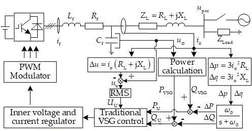
The overall control block diagram of the microgrid inverter using a traditional VSG control strategy is shown in
Figure 1. To simplify the analysis, the distribution generators are replaced by a direct current (DC) source in the main circuit.
is the voltage of the DC source;
is the filter inductor current;
,
, and
denote the filter resistance, the filter inductor and the filter capacitor, respectively;
and
denote the inverter’s output voltage and current, respectively;
is the connecting line impedance from DG to the point of common coupling (PCC).
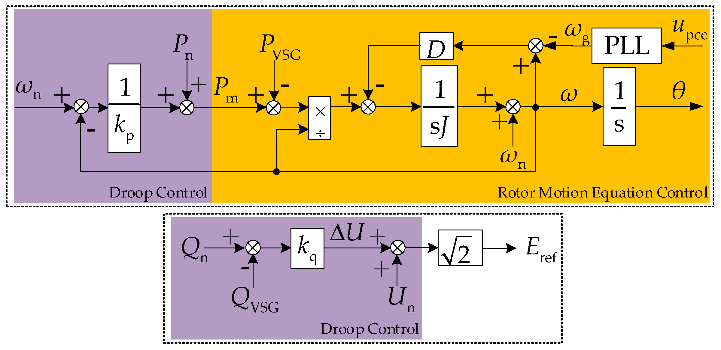
The traditional VSG controller uses a classic second-order model of a synchronous generator, as shown in
Figure 2.
In
Figure 2,
is the voltage of the AC bus. The rotor motion equation and the droop control equation obtained from
Figure 2 can be expressed as
where
and
are the angular frequency and the rated angular frequency of the SG, respectively;
is the angular frequency of the power grid;
is the power angle of the SG;
is the effective value of the rated voltage;
and
are the input and output active power, respectively;
is the output reactive power;
and
represent the active and reactive power reference, respectively;
is the moment of inertia, and
is the damping coefficient;
and
are the droop coefficients of active and reactive power, respectively. Note that
and
are obtained by the power calculation of the output voltage
and the output current
, which means that the traditional VSG control strategy uses the voltage and current data collected from the inverter side of the connecting line as the direct control variables.
2.2. Decoupling Effect of Virtual Impedance Method Considering the Terminal Droop Characteristics of Connecting Line
In a low-voltage microgrid, the premise of realizing parallel operation of inverters is that the output power and droop characteristics of a single inverter are not affected by the connecting lines. Taking the virtual negative resistance method as an example, the terminal decoupling effect of the connecting line is discussed. The equivalent circuit is shown in
Figure 3. Point A corresponds to the output of the inverter, point B represents the inverter side of the connecting line, and point C represents the terminal of the connecting line.
is the virtual negative resistance.
Point A is with active and reactive power decoupling [
17]. Assuming that the value of the added virtual negative resistance is large enough to offset the resistance value of the connecting line, the equivalent connecting line can be regarded as purely inductive consequently. It can be obtained from [
17] that that the active and reactive power of the terminal of the connecting line are also decoupled, namely point C with power decoupling.
On the basis of the above conclusion about decoupled point C, it is assumed that applying the droop control strategy with active power coefficient
and reactive power coefficient
to point A while applying
and
to point C, whose control equations are as shown in Equation (2) and (3), respectively. The terminal decoupling effect of the virtual impedance method considering the droop coefficient can be measured by verifying whether
equals
and
equals
or not.
Considering that
,
and
when there is no load. For
being a global variable,
and
. Assuming a unidirectional power flow from source to load, the active power loss of the connecting line and virtual impedance is recorded as
. The active power droop control equation is rewritten at the inverter side and combined with the terminal one:
thus,
The voltage drop and reactive power loss caused by the connecting line and virtual impedance are recorded as
and
. The reactive power droop control equation is rewritten at the inverter side:
that is,
It can be seen from Equations (5) and (8) that since the active and reactive power droop control strategies are realized by controlling the measurement data from the inverter side of the connecting lines, the user-side droop coefficients will be affected by the power loss and voltage drop caused by the connecting lines, which leads to higher values of the terminal coefficients. The droop coefficient at different locations is closely related to the connecting line parameters. Therefore, a line compensation is required to realize an equal between the actual user-side droop coefficient and the given value to ensure its controllability.
2.3. Improved VSG Control Strategy Considering the Precise Control of Droop Coefficient
The proposed VSG control strategy is as follows: The active and reactive power in the traditional droop equation is extended from the inverter-side to the user-side of the connecting line, that is, the droop control point is extended to the terminal of the connecting line.
After extending the control point, there is no need for the meaning of the frequency in the droop equation to be changed since the steady-state frequency is a global variable, while the value of the voltage controlled in the droop equation needs to be changed from the inverter-side to that of the terminal; the droop coefficients and the reference values do not need to be changed.
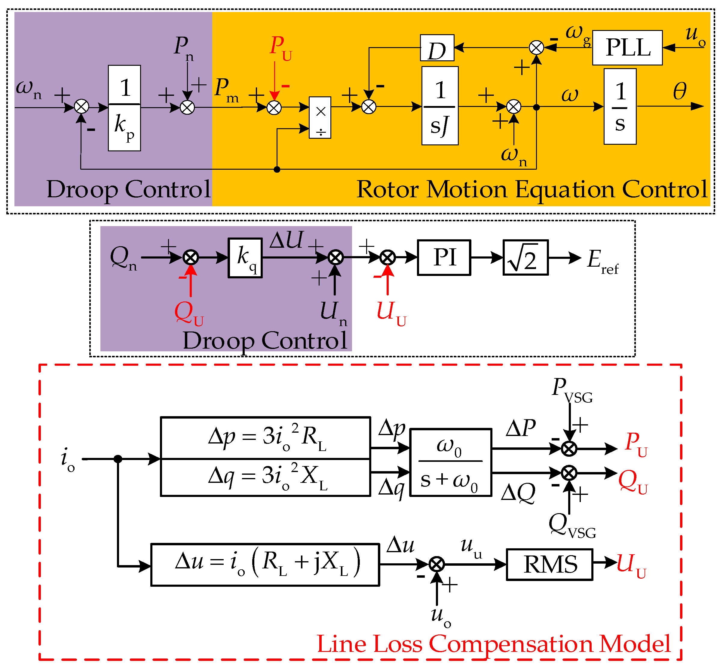
In order to ensure the locality of the microgrid control quantity, the required terminal data is obtained by giving line loss compensation to the inverter-side data, which can be collected directly. To summarize, the block diagram of the improved VSG control strategy is shown in
Figure 4.
, and are the active power, reactive power and voltage at the terminal of the connecting line obtained by the line loss compensation, respectively; is the effective value of the terminal voltage. The output current collected directly is used to calculate the power loss and the voltage drop of the line. The calculated power and voltage of the terminal are fed back to the VSG control to complete the subsequent control steps.
The improved VSG control strategy takes the connecting line impedance into account in the inverter control so that the user-side power is under direct control. At this time, there is a direct correspondence between the output power of the self-synchronizing voltage source and the user-side requirement only, which is not affected by the connecting line
Therefore, on the basis of the proposed idea, there is no coupling between the active and reactive power at the terminal, and the terminal droop coefficient can be guaranteed to be equal to the given value due to there being no extra loss caused by the connecting line. In addition, the improved strategy keeps the user-side voltage under control, avoiding voltage deviation at the user side caused by the voltage drop of the connecting line and virtual impedance.
It can be concluded that the improved VSG control strategy uses the inverter-side data to realize the direct control of the terminal variables indirectly. The proposed idea relies only on local information and does not require communication, which ensures the local robustness of the control. Furthermore, the controllability of the droop characteristics at the terminal of the connecting line realizes the “plug and play” of the micro-source effectively.
3. Coordinated Operation of Multi-Parallel Self-Synchronizing Voltage Sources
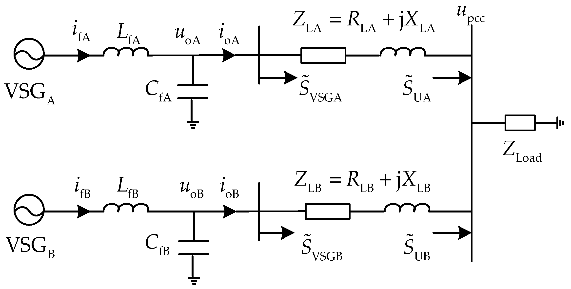
The advantage of the distributed microgrid is allowing multiple voltage sources to be in parallel operation. To study the control method of a single self-synchronizing voltage source is to make it serve in multi-parallel inverters operation. The simplified equivalent diagram of the two self-synchronizing voltage sources parallel system is shown in
Figure 5.
The coordinated control between the multi-parallel self-synchronizing voltage sources is intended to realize a reasonable power sharing at the user side, that is, the voltage sources output active and reactive power proportionally according to their capacities. As described in the previous section, the droop control decides the steady-state output power of the self-synchronizing voltage source, so the static precise power sharing of the multi-parallel voltage sources is also achieved by the droop control. However, not only the static distribution, but also the power sharing in dynamic processes is worthy of attention. When disturbance occurs in the microgrid, there is an imbalance between the power supply and demand. In the dynamic process before reaching a new stable operating point, the parallel voltage sources need to distribute the imbalance reasonably as well. Based on the above ideas, this section realizes the coordinated operation of multi-parallel self-synchronizing voltage sources in terms of static and dynamic performance through proposed control methods.
3.1. Static Parallel Coordinated Operation Control of Multi-Voltage Sources
The improved VSG control strategy proposed in this paper can achieve power decoupling and the desired droop characteristics at the terminal of the connecting line. In addition to realizing power decoupling, the multi-parallel system also needs to address the issues of power sharing. The improved droop control equation obtained from
Figure 4 is shown in Equation (9).
It is known that the given value of the droop coefficient is inversely proportional to the capacity of the voltage source. Due to this, the steady frequency is a global variable,
, and the active power droop equation can be rewritten as
It can be seen that the active power at the terminal of the connecting line can be shared according to the ratio of the voltage sources capacity.
For reactive power distribution, the parallel voltage sources are connected at the terminal of the connecting line, whose voltage is that of the PCC; thus,
. A PI controller is used to feedback the RMS value of the PCC voltage, which is obtained by the line loss compensation. Due to the proportional and integral, the input of the PI controller is zero during steady-state operation. Therefore,
is guaranteed to be achieved. The reactive power droop equation can be rewritten as
It can be seen that the reactive power at the terminal of the connecting line can be shared according to the ratio of the voltage source capacity.
In conclusion, the improved VSG control method can realize reasonable sharing of static active and reactive power at the terminal of the connecting line when multiple self-synchronizing voltage sources operate in parallel.
3.2. Dynamic Parallel Coordinated Operation Control of Multi-Voltage Sources
VSG technology endows the power electronic devices with inertia characteristics, and the transition process brought by virtual inertia mitigates the rapid fluctuation of frequency and power effectively when disturbance occurs. When there is one single self-synchronizing voltage source operating, the transition time can be set according to actual needs. However, when multiple self-synchronizing voltage sources are operated in parallel, the differences in the transition time of each unit will affect the dynamic coordinated operation of multiple machines and the synchronism of each voltage source. Take a sudden increase in load for instance, if the small-capacity power generation has a shorter response time, the unit will take on more load. This phenomenon is contrary to the control idea of reasonably distributing power between parallel multi-voltage sources.
In order to study the transition process consistency issues according to the capacities of multiple self-synchronizing voltage sources, the rotor equation is rewritten with the inertia time constant. Considering the angular frequency as a global variable, the mechanical power variation caused by the angular frequency difference between the voltage source and the system is ignored. Therefore, the equation of the rotor motion is simplified, as shown in Equation (12).
where
;
and
are the pole pair and rated capacity of the self-synchronizing voltage source, respectively, and the pole pair is generally taken as 1.
The operating points are set as follows: Initially, the self-synchronizing voltage source operates stably at point M; after disturbance, the operating point moves to point N. The rotor equations before and after disturbance are shown in Equations (13) and (14), respectively.
Equation (15) can be obtained from the initial stable operating point:
When the system is disturbed by
from the user side, the output of the voltage source will change from
to
immediately, while the mechanical power will not have been activated yet. At this time, the output power before and after the disturbance satisfies
, and Equation (16) can be obtained by combining Equation (15):
According to the
droop control equation, the relationship between the variation of active power
and that of the angular frequency
is
In order to facilitate the intuitive analysis of the transition time, let
, and then, the above formulas are combined to obtain Equation (18):
So,
where
. It can be known from Equation (19) that in order to ensure equal transition time of the parallel self-synchronizing voltage sources, the virtual inertia should be set inversely proportional to the ratio of the active power droop coefficient to the rated capacity, described as Equation (20):
As is known, the damping coefficient is related to the droop characteristic. In order to achieve the reasonable power sharing of the voltage sources, the damping coefficient is set inversely proportional to the ratio of the active power capacity [
18].
In summary, according to the matching principle of virtual rotor characteristics, the transition time can be consistent by setting the inertia and damping coefficient of each voltage source properly, which can achieve the dynamic coordination operation of multi-parallel self-synchronizing voltage sources. The specific principles are as follows:
(1) when the capacities of the voltage sources are the same, the virtual inertia and damping coefficient of each unit are set to be equal;
(2) when the capacities of the voltage sources are different, the virtual inertia is set inversely proportional to the ratio of the active power droop coefficient to the rated capacity, and the damping coefficient is set inversely proportional to the ratio of the active power capacity.
In conclusion, when there is disturbance in the microgrid or the power grid, the self-synchronizing voltage sources, controlled by the proposed VSG control strategy combined with the virtual rotor characteristic matching principle, can participate in the sharing and adjustment of the disturbance power together, ensuring a self-stabilizing mechanism in the microgrid. The disturbed microgrid eventually reaches a new stable state.
4. Simulation Verification
In order to verify the effectiveness of the improved VSG control strategy and the matching principle proposed in this paper, the model of the self-synchronizing voltage source in the distributed microgrid is built based on the MATLAB/Simulink simulation platform. The simulation verification includes the operation characteristics of single machine, dual-machine parallel system and grid-connection switching. Simulation parameters are shown in
Table 1.
4.1. Operation Characteristics of Single Self-Synchronizing Voltage Source
The islanding microgrid model with a single self-synchronizing voltage source is established. The R/X ratio and length of the connecting line vary separately. In comparison, the power coupling and droop characteristics are analyzed without the decoupling method, with the virtual impedance method and with the proposed VSG control method by using two indexes: The actual terminal power decoupling effect and the actual terminal droop coefficient, fit using the least squares method. The simulation parameters of the single self-synchronizing voltage source are listed in
Table 2.
4.1.1. Power Decoupling Effect at the Terminal of the Connecting Line
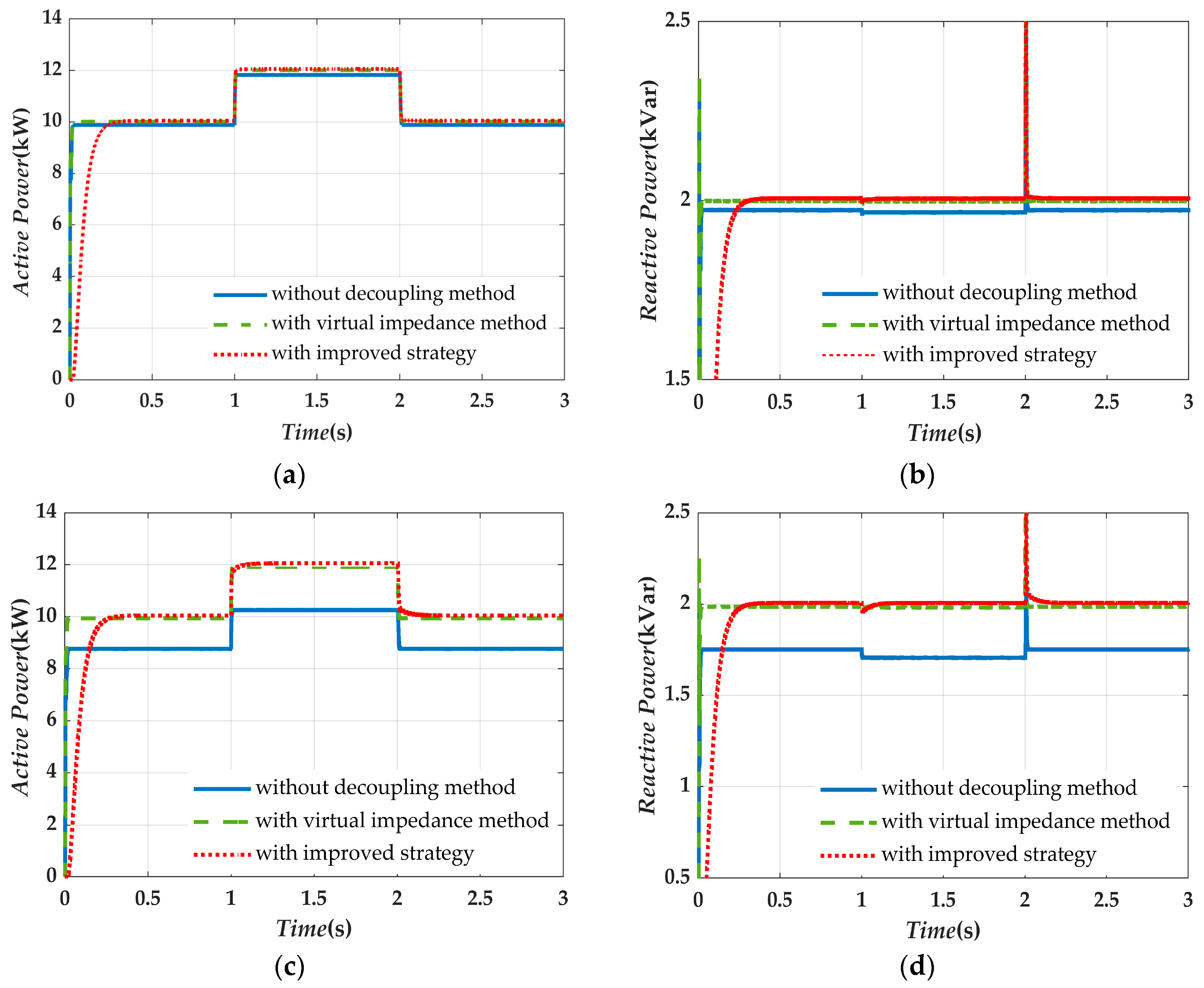
Working conditions are set as follow: The active power load of the islanding microgrid is 10 kW from 0 s < t < 1 s and is changed to 12 kW at 1.0 s; when t = 2 s, the microgrid returns to the initial state, and the reactive power load keeps 2 kVar during the simulation period.
(1) Connecting lines with different R/X ratios
The connecting line impedances are respectively set as (a)
, with small resistance, and (b)
, with large resistance. On the premise of not affecting the stable operation of the system, the virtual negative resistance is set as (a)
and (b)
. The active and reactive power waveforms at the terminal of the line with different R/X ratios are shown in
Figure 6.
It can be seen from
Figure 6a,b that without the decoupling method, the reactive power varies with the active power due to the coupling, and the active and reactive power at the terminal of the connecting line cannot meet the load demands. With the virtual impedance method, the value of the virtual negative resistance is large enough to ensure an inductive environment. Therefore, the terminal reactive power is basically not affected by the active power, and the coupling extent is lowered. Compared to the previous situation, the terminal output power can meet the load demand relatively. However, considering the stability of the system, the virtual negative resistance cannot completely offset the line resistance, so the terminal active power will still be slightly lower than the demand value due to the active power loss. With the proposed VSG control scheme, the reactive power remains unaffected by the active power basically, and the active and reactive power at the terminal can meet the requirements of the user side, realizing steady-state decoupling. Since the R/X ratio of the line is relatively low in this case, the influence caused by the coupling is relatively small, so the compensation and decoupling effect of the improved scheme are not obvious enough.
As shown in
Figure 6c,d, when the R/X ratio of the line is relatively high, compared to
Figure 6b, it is more obvious to see that the reactive power is affected due to the coupling. In addition, the terminal active and reactive power are significantly lower than the value of the load demand, which cannot meet the users’ requirements. In addition, the virtual impedance method still inevitably has the issues of the power loss while basically achieving power decoupling. However, the improved control scheme can still achieve steady-state decoupling and meet the power requirements accurately. In summary, it is considered that within a reasonable range, the higher the R/X ratio of the connecting line is, the more obviously the advantages of the proposed scheme show.
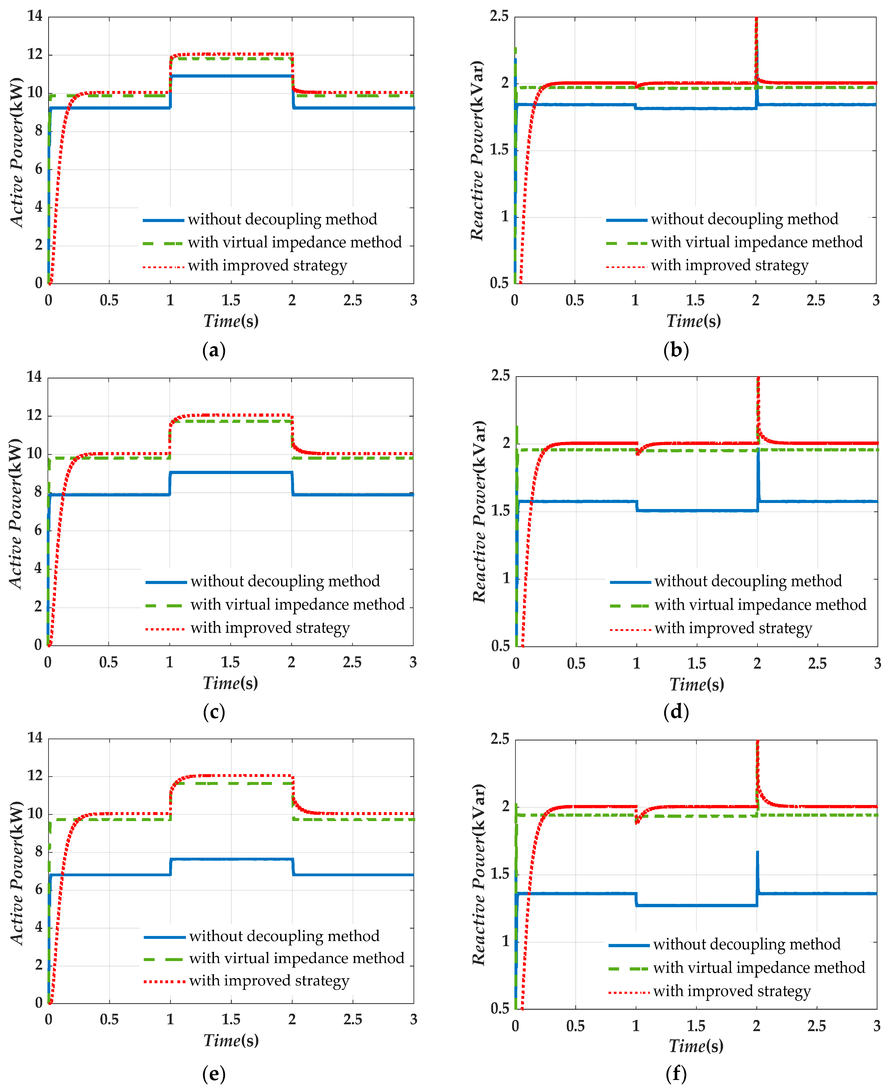
(2) Connecting lines with different lengths
The impedance value of the connecting line is taken as
per kilometer, and the length of the connecting line is set to 1 km, 3 km and 5 km, respectively. The virtual negative resistance is set to −0.5 Ω, −1.7 Ω and −2.9 Ω, correspondingly. The active and reactive power waveforms at the terminal of the line are shown in
Figure 7.
It can be seen from
Figure 7 that with no decoupling strategy, the terminal active and reactive power have coupling. As the length of the connecting line increases, the output power injected to the user side decreases due to the increasing power loss on the line, and ultimately the users’ demand cannot be met. With the virtual impedance method, the extent of the power coupling is significantly lowered, but there are differences between the actual output power at the terminal and the load. When performing the improved control method, the terminal output power is basically not affected by the variation of the length of the line. The steady-state decoupling between active and reactive power is achieved, meanwhile the output can meet the power required more accurately. In summary, it is considered that the longer in length the connecting line is, within a reasonable range, the more obviously the advantages of the proposed scheme show.
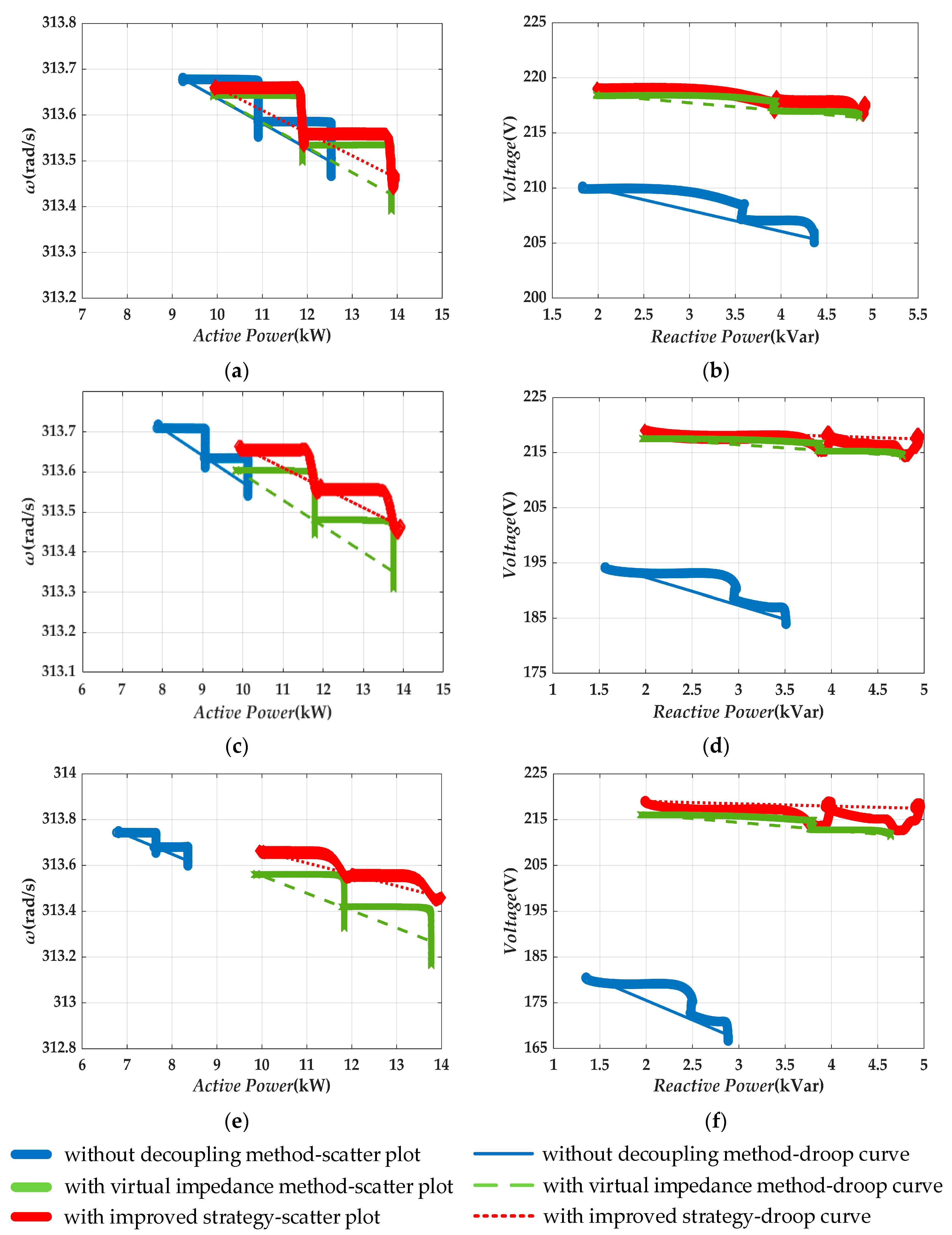
4.1.2. Droop Coefficient at the Terminal of the Connecting Line
Working conditions are set as follows: The active power load of the islanding microgrid is 10 kW from 0 s < t < 1 s and is changed to 12 kW at 1.0 s and to 14 kW at 2.0 s. The reactive power load is 2 kVar from 0 s < t < 1 s and is changed to 4 kVar at 1.0 s and to 5 kVar at 2.0 s.
(1) Connecting lines with different R/X ratio
The values of the connecting line and virtual impedance are the same as in
Section 4.1.1.(1). Terminal droop curves of the active power-frequency and reactive power-voltage obtained by fitting are shown in
Figure 8.
The droop coefficients acquired by fitting method are listed in
Table 3.
(2) Connecting lines with different lengths
The parameters of the connecting line and virtual impedance are the same as in
Section 4.1.1.(2). Terminal droop curves of the active power-frequency and reactive power-voltage obtained by fitting are shown in
Figure 9.
The droop coefficients acquired by fitting method are listed in
Table 4.
From the above simulation results, it can be seen that the system uses the inverter-side active and reactive power for the droop control strategy when there is no decoupling method or with the virtual impedance method. Based on the given conditions of the line, the terminal droop coefficient is affected by two aspects when the decoupling method is not used. On the one hand, the increase of the R/X ratio enhances the coupling; on the other hand, the increase of the line impedance brings larger line power loss and the voltage drop. Both of them can cause deviation of the droop coefficient. The longer the length of the connecting line, the larger the line impedance value is, and the more obviously the deviation of the droop coefficient shows. When with virtual impedance decoupling method, the degree of deviation is decreased but still affected by the line impedance. After being compensated by the improved VSG scheme, the terminal droop coefficient does not vary with the varying impedance value substantially, so that the user-side droop coefficient can be controlled accurately.
From another perspective, the reactive power droop curve shows that large resistance of the connecting line causes voltage deviation at the terminal, which has a bad effect on the load side voltage. However, with the improved scheme, the terminal voltage does not change because of the connecting line impedance, which effectively maintains the normal level of the voltage on the user side.
4.2. Parallel Operation Characteristics of Self-Synchronizing Voltage Source
The islanding microgrid model with two self-synchronizing voltage sources in parallel operation is established, as shown in
Figure 5 To verify the effectiveness of the proposed scheme, the power sharing performances at the terminal of the connecting line adopted by different methods are analyzed in comparison, including without the decoupling control method, with the virtual impedance method, and with the improved VSG control method combined with the matching principle.
The capacity ratio of the self-synchronizing voltage source A and B is set to 2: 1, the connecting line impedance to
, and the virtual negative resistance to −0.67 Ω. The specific simulation parameters are listed in
Table 5.
The working conditions are set as follows:
(a) Initial state: The islanding microgrid is with 30 kW active power and 3 kVar reactive power load.
(b) When t = 2 s, 3 kW active power load and 3 kVar reactive power load are accessed.
(c) When t = 3.5 s, the microgrid returns to the initial state.
The active and reactive power sharing performance of the parallel system is shown in
Figure 10.
As shown in
Figure 10a,b, the large resistance in the connecting line causes a coupling between the active and reactive power. The active power sharing is obviously poor, and the sum of the inverters’ output is not equal to the load demand. Due to the large resistance, VSG
B outputs reactive power while VSG
A absorbs. This phenomenon becomes more severe after the load power step.
Figure 10c,d are the waveforms of power sharing with the virtual impedance method. There is a relatively proportional sharing of active power in the ratio of 2:1 in
Figure 10c compared to the result in
Figure 10a. From the point of view of reactive power output, although both units output reactive power, the smaller units take on more load. Therefore, the active power sharing performance is improved, but the reactive power distribution is still poor.
Figure 10e,f are the waveforms of power sharing with improved VSG control scheme combined with the virtual rotor characteristics matching method. It can be seen that during the simulation, the proposed strategy enables the proportional sharing of both active and reactive power in the ratio of 2:1, and the transition process of the two self-synchronizing voltage sources is synchronized, which realizes autonomously synchronous operation of multiple voltage sources in a distributed microgrid. However, the reason why the transient time seems relatively longer needs further analysis.
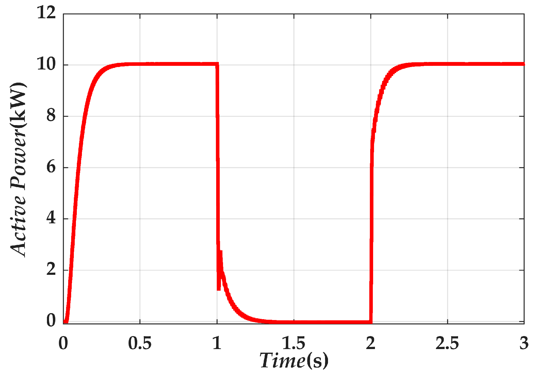
4.3. Grid-Connection Switching Characteristics of Self-Synchronizing Voltage Source
To verify the self-synchronization and stability of the self-synchronizing voltage source based on the proposed control strategy when grid-connection switching, the infinite power grid model regarded as a three-phase ideal voltage source with 380 V and 50 Hz is used for simulation. The reference active power of the self-synchronizing voltage source is , and the connecting line impedance is . The other simulation parameters are the same as above. The working conditions are set as follows:
(a) Initial state: Islanding microgrid operates with single self-synchronizing voltage source and 10 kW active power load.
(b) When t = 1 s, the microgrid accesses the infinite power grid.
(c) When t = 2 s, the microgrid retreats from the grid.
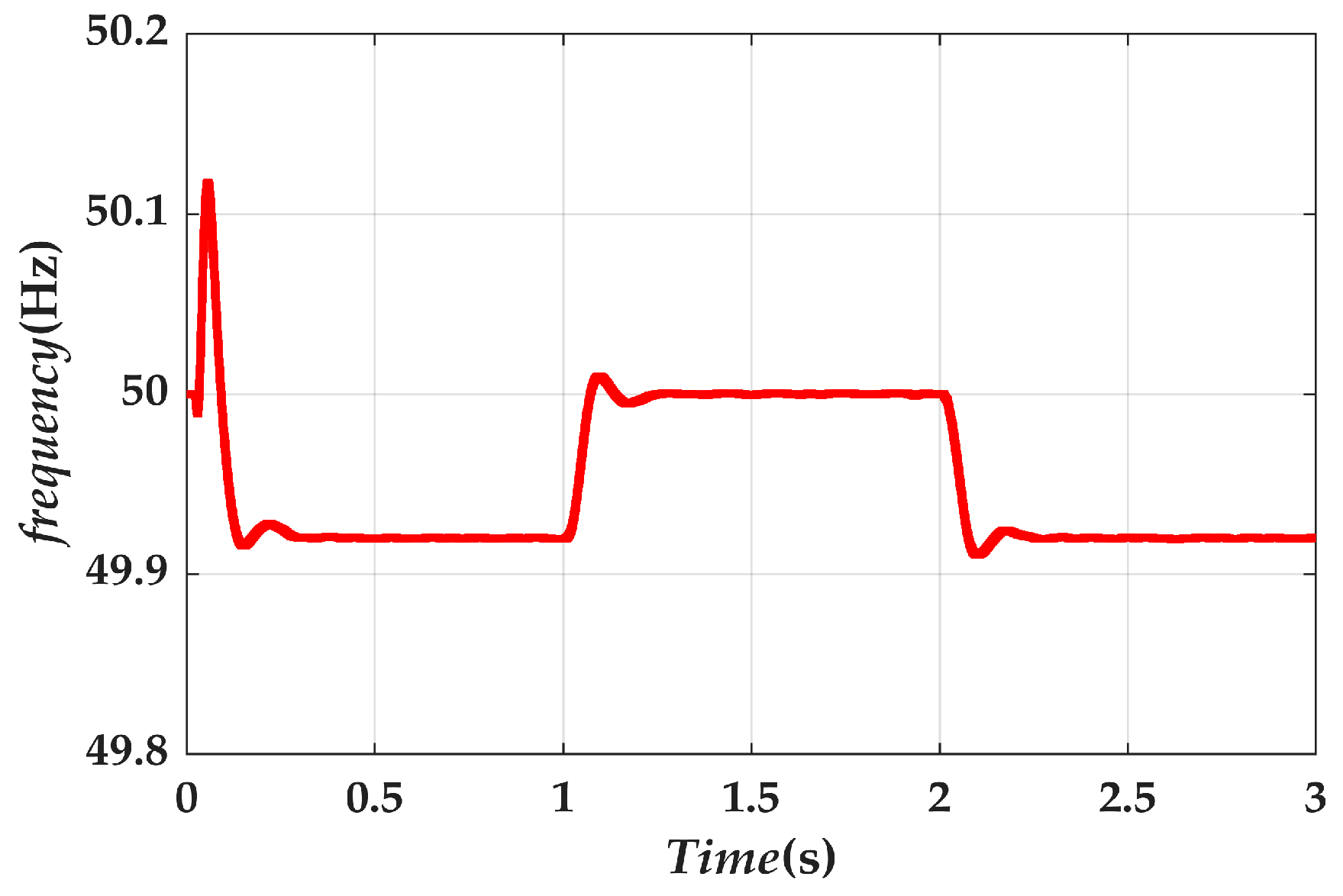
The output active power at the terminal of the connecting line and the frequency of the self-synchronizing voltage source are shown in
Figure 11 and
Figure 12, respectively.
(1) 0 < t < 1 s, the self-synchronizing voltage source outputs 10 kW active power at the terminal, which meets the load requirements precisely. According to the active power-frequency droop equation, the calculated system frequency is 49.92 Hz. The simulation result is equal to the theoretical value.
(2) When t =1 s, the microgrid accesses the infinite power grid. During the grid connection, the microgrid automatically adapts to the operating frequency of 50 Hz, as is set, and the output active power varies to the reference value of 0 kW, accordingly.
(3) When 2 < t < 3 s, the microgrid is disconnected from the power grid and resumes autonomous operation. The value of the power and frequency is consistent with that in 0 < t < 1 s.
The simulation results verify that the self-synchronizing voltage source is capable of stable grid-connection switching without changing the control mode, which endows the microgrid with autonomy.
It should be noted that when performing the virtual impedance decoupling method, the simulated value of the virtual impedance is selected to be rather large in order to offset the line resistance as much as possible. In fact, there is a critical stability value for the virtual impedance [
24]. When the virtual negative resistance value is close to or even equal to the line resistance value, the decoupling can be achieved to the greatest extent, but the system may face instability at the same time. Therefore, compared with the virtual impedance method, the improved VSG control strategy proposed in this paper avoids the critical stability issues.


