Article

Optimization Design of Injection Strategy for Surfactant-Polymer Flooding Process in Heterogeneous Reservoir under Low Oil Prices

1
College of Petroleum Engineering, Yangtze University, Wuhan 430100, China
2
Research Institute of Exploration and Development of Shengli Oilfield, SINOPEC, Dongying 257000, China
3
Engineering Technology Research Institute of Xinjiang Oilfield Company, CNPC, Karamay 834000, China
*
Author to whom correspondence should be addressed.
Energies 2019, 12(19), 3789; https://doi.org/10.3390/en12193789
Submission received: 28 July 2019 / Revised: 5 September 2019 / Accepted: 4 October 2019 / Published: 7 October 2019
(This article belongs to the Special Issue Enhanced Oil Recovery 2020)

Abstract

:
Surfactant–polymer (SP) flooding has significant potential to enhance oil recovery after water flooding in mature reservoirs. However, the economic benefit of the SP flooding process is unsatisfactory under low oil prices. Thus, it is necessary to reduce the chemical costs and improve SP flooding efficiency to make SP flooding more profitable. Our goal was to maximize the incremental oil recovery of the SP flooding process after water flooding by using the equal chemical consumption cost to ensure the economic viability of the SP flooding process. Thus, a systematic study was carried out to investigate the SP flooding process under different injection strategies by conducting parallel sand pack flooding experiments to optimize the SP flooding design. Then, the comparison of the remaining oil distribution after water flooding and SP flooding under different injection strategies was studied. The results demonstrate that the EOR efficiency of the SP flooding process under the alternating injection of polymer and surfactant–polymer (PASP) is higher than that of conventional simultaneous injection of surfactant and polymer. Moreover, as the alternating cycle increases, the incremental oil recovery increases. Based on the analysis of fractional flow, incremental oil recovery, and remaining oil distribution when compared with the conventional simultaneous injection of surfactant and polymer, the alternating injection of polymer and surfactant–polymer (PASP) showed better sweep efficiency improvement and recovered more remaining oil trapped in the low permeability zone. Thus, these findings could provide insights into designing the SP flooding process under low oil prices.

Graphical Abstract

1. Introduction

Water flooding is recognized as an important secondary recovery method because it is economically advantageous for the development of oil reservoirs. With the maturity of a water flooded oil reservoir, due to the existence of a thief zone, the phenomenon of injected water channeling occurs, resulting in poor sweep efficiency and low ultimate oil recovery. With the increasing demand of crude oil consumption, it is of vital importance to develop more effective techniques to enhance oil recovery in mature water flooding reservoirs. Chemical enhanced oil recovery (CEOR) processes have demonstrated great potential for recovering more remaining oil in mature reservoirs after water flooding [1]. CEOR processes can be mainly categorized as: polymer flooding [2,3,4,5], surfactant flooding [6,7,8,9,10,11,12,13,14,15], surfactant–polymer (SP) flooding [16,17,18,19,20], and alkali–surfactant–polymer (ASP) flooding [21,22,23,24,25]. Polymers can increase the viscosity of the injected water phase and reduce the mobility ratio between water and oil, thus improving the sweep efficiency. By reducing the oil–water interfacial tension, surfactants can mobilize the oil trapped by capillary forces. Alkali can react with acid in crude oil to generate in situ surfactants and reduce oil–water interfacial tension. By combining the synergistic effects of the polymer, surfactant, and alkali, alkali–surfactant–polymer (ASP) flooding has proven to be effective for enhancing oil recovery and is applied in many oilfields. Although ASP flooding can achieve a higher incremental oil recovery, the key issues associated with ASP are scale formation and the disposal of produced emulsions enhanced by alkali.
Therefore, to avoid the problems of scale formation and emulsification in ASP flooding, surfactant–polymer (SP) flooding is recognized as one of the most promising CEOR technologies and has gained more interest as a method of enhancing oil recovery in recent years. During the era of high oil prices, due to the need to increase oil production, SP flooding pilot tests were carried out in many different oilfields, especially in China such as the Shengli oilfield, Daqing oilfield, Xinjiang oilfield, Dagang oilfield, and so on. However, when the oil prices are low, due to the high chemical cost, uncertainty of the flooding process, and complex reservoir condition [26], the economic benefit of SP flooding process is unsatisfactory. The primary reason for this phenomenon is that chemical costs dominate the SP flooding process. For the Shengli oilfield, the SP flooding pilot tests have been successfully carried out since 2003, and the EOR efficiency has been significantly improved. The pilot test results demonstrated that SP flooding could achieve an incremental oil recovery of 12.1% after water flooding [17]. However, during the prevailing low oil price period, low oil prices make SP flooding less profitable. It is estimated that when the oil prices are lower than $60/bbl, the SP process is economically unjustifiable.
The main challenge of SP flooding at the prevailing low oil prices is to reduce the cost. To overcome the challenge of low oil prices and improve the economic benefit of SP flooding, a corresponding strategy was put forward to minimize the cost of chemical agents including the polymers and surfactants required to produce the same amount of oil. Therefore, developing new economic effective chemical agents, optimizing the chemical formulation, and designing proper flooding process are critical for achieving economically viable flooding during field pilots. Extensive studies have been conducted on developing new chemical agents and optimizing the proper chemical formulation [27,28]. However, developing low cost chemical agents and their application in field pilot tests is time consuming. Moreover, the surfactant–polymer formulation for the Shengli oilfield has been optimized. Thus, it is necessary to investigate the efficiency of SP flooding under different injection strategies. Previous studies have focused on the numerical simulation on SP flooding [29,30,31,32,33,34,35]. Daripa and Dutta proposed a hybrid numerical method to solve a coupled system of nonlinear equations that arises in modeling multicomponent, two-phase porous media flow during the SP flooding process [34]. The numerical method was validated and can be used to evaluate the performance of different chemical flooding schemes. Additionally, the convergence behavior of the hybrid numerical method has been studied by considering one-component, two-phase porous media flow [35]. To the best of our knowledge, little research has been done on the SP flooding optimization by physical simulation experimental study. Hence, the objective of this study was to demonstrate how to maximize the incremental oil recovery of the SP flooding process after water flooding by using the equal chemical consumption cost to ensure the economic viability of the SP flooding process. First, a series of parallel sand pack flooding experiments were performed to investigate the EOR efficiency of the SP flooding process after water flooding under different injection strategies where the chemical consumption costs in the SP flooding process under different injection strategies were equal. Moreover, the comparison of the remaining oil distribution under different injection strategies was studied to reveal the underlying EOR mechanism governing the flooding efficiency. In general, we hope that these findings will contribute to the design of a proper injection strategy for the SP flooding process after water flooding in the Shengli oilfield under low oil prices.

2. Experimental Study

2.1. Materials

The polymer used in this experimental study was partially hydrolyzed polyacrylamide (HPAM) with a viscosity-average molecular weight of 2.6 × 10⁷ provided by the Shengli oilfield. The two types of surfactants used in this experimental study were petroleum sulfonate (SLPS) and nonionic surfactant (GD-3) provided by the Shengli oilfield. The formulation of the surfactant–polymer (SP) was designed and optimized by the Shengli oilfield. The surfactant used in the SP formulation was a mixture of SLPS and GD-3 with a concentration ratio of 1:1. The surfactant concentration used in the SP formulation was 0.4 wt%. The crude oil used in this experimental study was provided by the Shengli oilfield. The viscosity of the crude oil was 68.5 mPa·s at 70 °C as measured by a DV-II Brookfield viscometer. Sodium chloride (NaCl), calcium chloride (CaCl2), magnesium chloride (MgCl2), and sodium bicarbonate (NaHCO3) were purchased from Aladdin Reagents Co. Ltd and used to prepare the simulated formation brine. The deionized water was obtained from our own laboratory. The ionic composition and concentration of the simulated formation brine are shown in Table 1.

2.2. Methods

2.2.1. Solution Preparation

The polymer solution was obtained by adding the polymer powder into the formation brine under mechanical stirring for approximately 8 h at ambient temperature. The surfactant solutions were prepared by mixing the surfactants with the formation brine thoroughly to obtain the required concentration. Then, the surfactant–polymer solutions were prepared by mixing the polymer, surfactant solution, and formation brine under mechanical stirring.

2.2.2. Parallel Sand Pack Flooding Test

The parallel sand pack flooding tests were carried out by using two sand packs (Φ2.5 cm × 50 cm) with different permeabilities to investigate the oil recovery efficiencies of two different surfactant–polymer flooding strategies. The high and low permeability sand packs were used in combination to simulate the reservoir heterogeneity. The high and low permeability sand packs were prepared as follows [36,37]: The sand packs were positioned vertically and filled with formation brine, then fresh quartz sand with different mesh sizes were added into the sand packs and packed by vibration.
After the sand packs were prepared, the porosity and permeability were measured by the volumetric methods and Darcy’s law, respectively. Then, after the required high and low permeability sand packs were obtained, experiments were performed following the injection sequence: crude oil saturation, initial water flooding, SP flooding, and finally extended water flooding. The experimental procedure can be described as follows. (1) Crude oil saturation period: The sand packs were oil-flooded until no water was produced. (2) Water flooding period: water flooding was terminated when the water cut was 95%. (3) Chemical slug injection period: chemical slug was injected under different injection strategies. (4) Subsequent water flooding period: Then, the subsequent water flooding was conducted again until the water cut was 98%. All the flooding tests were carried out at 70 °C. The injection rate was 1.0 mL·min−1. Figure 1 shows the schematic diagram of the experimental setup for parallel sand pack flooding and Figure 2 shows the experimental procedure and the chemical slug injection strategy.
To simulate the SP flooding process, the chemical slug design included the pre-slug and main SP slug. In this study, the pre-slug was the same and the main SP slug was different. The main SP slug was designed and injected by different injection strategies. Table 2 summarizes the chemical slug design under different injection strategies. The design principles of the chemical slug for different injection strategies are as follows. (1) For the polymer alternating surfactant–polymer injection strategy, the main slug was composed of the high concentration polymer slug and low concentration surfactant–polymer slug. (2) The surfactant concentration of the main slug was the same for different injection strategies. (3) The chemical consumption costs of each designed main chemical slug were equal under different injection strategies.

2.2.3. Plate Sand Pack Flooding Test

The comparison of the remaining oil distribution under different injection strategies was studied by performing flooding experiments on the plate sand pack model with a saturation acquisition device. The length, width, and depth of the plate sand pack model was 50 cm, 25 cm, and 1.8 cm, respectively. Figure 3 shows the schematic diagram of the experimental setup for the plate sand pack flooding. The experimental setup was composed of four parts: ISCO pump (Teledyne ISCO company, Lincoln, Lincoln, Nebraska, USA), sand pack model, Inductance-Capacitance-Resistance (LCR) digital bridge (Changzhou Tonghui Electronic Co., Ltd, Changzhou, China), and the oil–water saturation acquisition control system [37]. The oil–water saturation can be obtained by measuring the resistivity. Fresh quartz sand of different mesh sizes was used to prepare the heterogeneous plate sand pack to simulate the high permeability and low permeability zone in the heterogeneous reservoir. The distribution of the high permeability and low permeability zone is shown in Figure 3. The permeability of the high permeability zone was about 4.0 μm2 and the permeability of low permeability zone was about 1.0 μm2.
The experimental flooding procedure is similar to that of parallel sand pack flooding.

3. Results and Discussion

3.1. EOR Efficiency of SP Flooding Process under Different Injection Strategies

Based on the experimental design shown in Table 2, four parallel sand pack flooding experiments were conducted to investigate the EOR efficiency of the SP flooding process under different injection strategies. Table 3 summarizes the basic properties of the sand packs used for the flooding experiments.

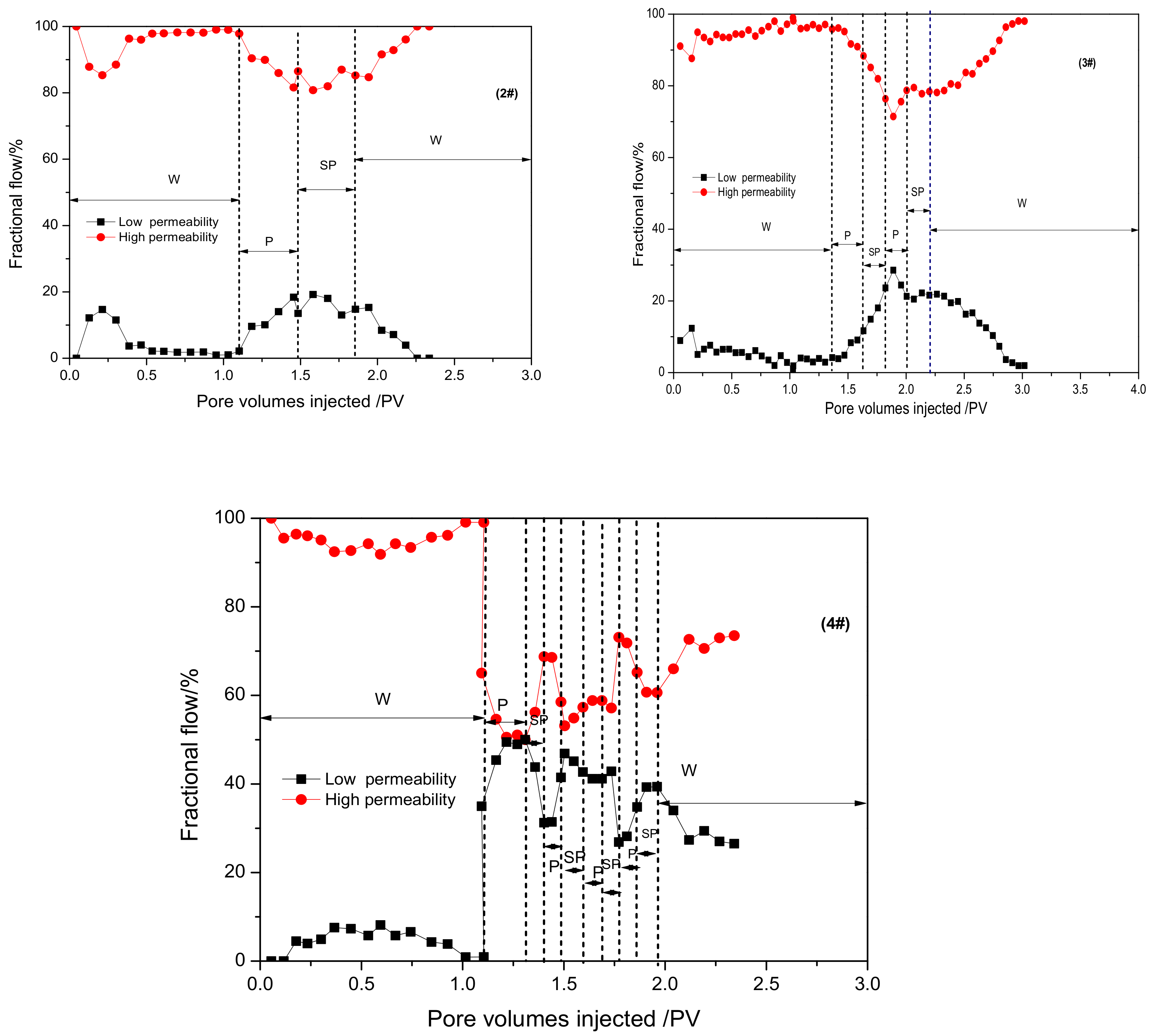
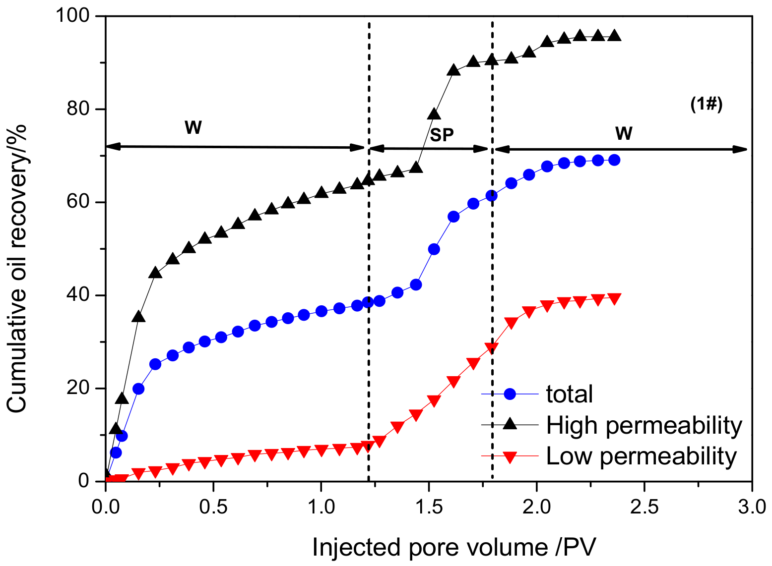
3.1.1. Fractional Flow Analysis

The mobility control ability plays an important role in improving the sweep efficiency of the SP flooding process. The mobility control ability of SP flooding under different injection strategies can be reflected by the changes in the fractional flow curve. The calculation method of fractional flow has been reported in our previously published papers [37,38].
Figure 4 and Figure 5 show the changes in fractional flows versus injected pore volumes under different injection strategies.
It can be seen that the changing trends of the fractional flow curve under the simultaneous injection strategy and alternation injection strategy were similar. First, due to the permeability contrast, the majority of the injection water enters into the high permeability zone, which leads to a poor water sweep efficiency. Then, at the stage of injecting the chemical slug, due to the existence of the preferred flow path of the injection water, the chemical slug can preferentially enter into the high permeability sand pack and reduce the mobility ratio of water and oil. Thus, the fractional flow of the high permeability sand pack decreases, while the factional flow of the low permeability sand pack increases. Finally, at the stage of subsequent water flooding, the subsequent injection water will break through the chemical slug gradually, resulting in increasing the fractional flow of the high permeability sand pack and decreasing the fractional flow of the low permeability sand pack. However, there are significant differences in the level of decreasing and increasing degree.
Moreover, there exists an obvious difference in the relative cumulative liquid intake volume of the high and low permeability layer. Thus, to characterize the difference in liquid intake volume, the relative liquid intake capacity was proposed. To further clarify the differences quantitatively, the cumulative liquid intake ratios of the high and low permeability layers were proposed, which represent the water intake ability. Thus, on the basis of the fractional flow curves, the cumulative produced liquid ratios of the high and low permeability sand packs during the periods of chemical slug injection and subsequent water flooding were calculated, which can contribute to analyzing the water intake ability for different layers with a permeability contrast. The cumulative produced liquid ratio of the high or low permeability sand pack is defined as the cumulative produced liquid of the high or low permeability sand pack to the total cumulative produced liquid.
Figure 6 illustrates the cumulative produced liquid ratios under different injection strategies. It can be clearly seen that the difference between the cumulative produced liquid ratio of the high and low permeability layers under simultaneous injection of the surfactant and polymer (SP) was greater than that of the alternating injection of the polymer and surfactant–polymer (PASP). When the injection strategy of the chemical slug was simultaneous injection, the cumulative produced liquid ratio of the high permeability layer was higher than 90%, while that of low permeability layer was lower than 10%. Compared with the simultaneous injection of the surfactant and polymer, the cumulative produced liquid ratio of the high permeability layer was lower under the alternating injection strategy. As the alternating cycle increases, the cumulative produced liquid ratio of the high permeability layer decreases and the low permeability layer increases. The higher the proportion of liquid absorption in the low permeability layer, the better the improvement of the sweep efficiency.

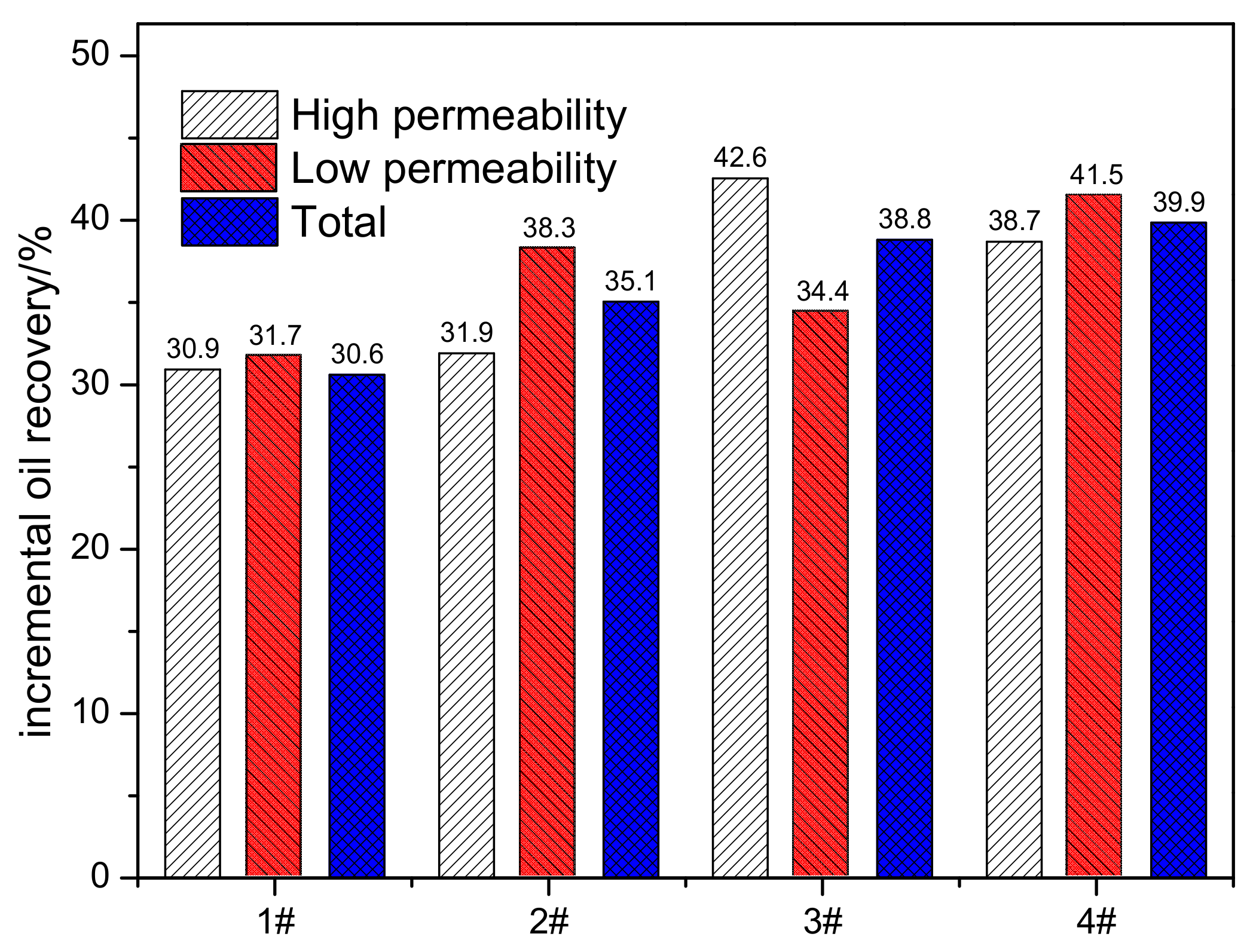
3.1.2. Incremental Oil Recovery Analysis

The fractional flow analysis results demonstrated that the alternating injection of the polymer and surfactant–polymer (PASP) showed better sweep efficiency improvement than the simultaneous injection of the surfactant and polymer (SP). Thus, to further demonstrate the EOR efficiency of the SP flooding process under different injection strategies, the cumulative oil recoveries at different flooding stages under different injection strategies are depicted in Figure 7 and Figure 8. The changing trends of cumulative oil recovery can be summarized as follows:
(1).
At the stage of the water flooding period, there exists a water-free oil production period. As the injected pore volume of the injection water increases, due to the permeability difference, the injected water enters into the high permeability layer and the water cut increases quickly. When the water cut reaches 95%, the water flooding is terminated and the total cumulative oil recovery is about 40%.
(2).
As the chemical slugs are injected through different injection strategies, due to the mobility control ability, the polymer increases the viscosity of the injection water and enlarges the sweep efficiency, which reduces the water intake volume of the high permeability sand pack and mobilizes the remaining oil in the low permeability sand pack.
(3).
Then, after SP flooding, as shown in Table 4 and Figure 9, the total incremental oil recovery of SP flooding under the simultaneous injection strategy was 30.6%, while that of SP flooding under the alternating injection strategy ranged from 35.06% to 39.86%. It was demonstrated that the alternation injection of polymer and surfactant-polymer (PASP) had a higher total incremental oil recovery than the simultaneous injection of the surfactant and polymer (SP). Moreover, as the alternating cycle increases, the incremental oil recovery increases. Based on the fractional flow analysis results, the alternating injection of the polymer and surfactant–polymer (PASP) showed a better sweep efficiency improvement ability than the simultaneous injection of the surfactant and polymer (SP). This indicates that more SP slugs were diverted into the low permeability sand pack. By combining the mobility control and oil displacement ability, more remaining oil in the low permeability sand pack can be recovered after water flooding.

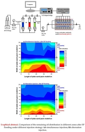
3.2. Comparison of the Remaining Oil Distribution under Different Injection Strategies

On the basis of the parallel sand pack flooding results for different injection strategies, it was demonstrated that when compared with the simultaneous injection of the surfactant and polymer, the EOR efficiency of the polymer alternating surfactant–polymer flooding was higher. To further investigate the potential reasons governing the differences in EOR efficiency under different injection strategies, a comparison of the remaining oil distribution after water flooding and SP flooding was studied.

3.2.1. The Remaining Oil Distribution after Water Flooding

The remaining oil distribution after water flooding under alternating injection and simultaneous injection strategies is depicted in Figure 10. The remaining oil distribution of the high permeability zone and low permeability zone after water flooding was similar. It was noted that the remaining oil saturation of the high permeability zone after water flooding was obviously lower than that of the low permeability zone. Moreover, there was a main water flow channel in the high permeability zone and a large percentage of oil distributed in the high permeability zone was recovered, whereas large amounts of remaining oil distributed in the region of the low permeability zone were not recovered. The difference in the remaining oil distribution in the high and low permeability zone can be attributed to the permeability contrast. Thus, it is of vital importance to enlarge the swept area, which can recover more remaining oil trapped in the low permeability zone.

3.2.2. The Remaining Oil Distribution after SP Flooding

To illustrate the differences in the swept area and remaining oil distribution, SP flooding was conducted under different injection strategies. Figure 11 shows the remaining oil distribution after SP flooding under simultaneous injection and alternating injection. Compared with the remaining oil distribution after water flooding, the remaining oil saturation in the high and low permeability zones was lower and the remaining oil in the high and low permeability zones could be recovered by SP flooding. It was noted that when compared with the simultaneous injection strategy, the remaining oil saturation in the low permeability zone after SP flooding was lower under the alternating injection strategy.

3.3. Mechanism Analysis

The main mechanisms governing SP flooding are enlarging the swept volume and improving the oil displacement efficiency. After water flooding in heterogeneous reservoirs, the remaining oil is mainly distributed in the low permeability zone, whereas little of the remaining oil is distributed in the high permeability zone (Figure 12a). Based on the analysis of fractional flow, incremental oil recovery, and remaining oil distribution, when the injection strategy is a simultaneous injection of the surfactant and polymer, most of the SP flooding slugs enter into the high permeability zone, as shown in Figure 12b. Although the SP flooding slug can play a role in improving the oil displacement efficiency in the high permeability zone, the remaining oil saturation in the high permeability zone is low, thus the contribution to the total oil recovery is small. Moreover, the more SP flooding slugs enter into the high permeability zone, the less SP flooding slugs enter into the low permeability zone. For less SP flooding slugs enter into the low permeability zone, the recovery of oil in the low permeability zone is low, as shown in Figure 12c.
When the injection strategy is alternating injection, the alternating injection of the polymer and surfactant–polymer (PASP) can fully play a role in improving the sweep efficiency and oil displacement efficiency. As the pre polymer slug can have a viscosity increasing effect that can increase the flow resistance of the high permeability zone, more SP flooding slugs can be diverted into the low permeability zone, as shown in Figure 12d. Then, the SP flooding slug can play a role in improving the oil displacement efficiency in the low permeability zone, resulting in a higher recovery of the low permeability zone, as shown in Figure 12e. Moreover, the remaining oil saturation in the low permeability zone was high, thus the contribution to the total oil recovery was high.

4. Conclusions

In this work, a series of experiments were performed to investigate how to maximize the incremental oil recovery of the SP flooding process after water flooding by using the equal chemical cost to ensure that the SP flooding process is more economically viable. Based on the experimental results, some final conclusions can be obtained as follows:
(1).
On the basis of parallel sand pack flooding results for different injection strategies, it was demonstrated that the alternating injection of the polymer and surfactant–polymer (PASP) showed a better sweep efficiency improvement ability than that of the simultaneous injection of the surfactant and polymer (SP). Moreover, the EOR efficiency of the polymer alternating surfactant–polymer flooding was higher. As the alternating cycle increased, the incremental oil recovery increased.
(2).
The comparison of the remaining oil distribution after water flooding and SP flooding under different injection strategies demonstrated that in comparison with water flooding, the remaining oil saturation after SP flooding was lower. It was found that SP flooding can improve oil displacement efficiency and enlarge the swept volume. Compared with the conventional simultaneous injection of the surfactant and polymer, alternating injection of the polymer and surfactant–polymer (PASP) showed a better sweep efficiency improvement and recovered more remaining oil trapped in the low permeability zone.
(3).
To maximize the incremental oil recovery of the SP flooding process after water flooding by using the equal chemical cost, it is crucial to enlarge the swept volume and mobilize the trapped oil in the low permeability zone. The proposed mechanism governing the differences in SP flooding under different injection strategies has been proposed.

Author Contributions

H.H. conceived and designed the experiments; Y.C. and H.L. performed the experiments; H.H. analyzed the data; Q.Y. and X.W. contributed reagents/materials/analysis tools; H.H. wrote the paper.

Funding

This work was supported by the National Natural Science Foundation of China (Project Number: 51604037) and the Research Institute of Exploration and Development of the Shengli Oilfield.

Conflicts of Interest

The authors declare no conflicts of interest.

References

  1. Liao, G.; Wang, Q.; Wang, H.; Liu, W.D.; Wang, Z. Chemical flooding development status and prospect. Acta Pet. Sin. 2017, 38, 196–207. [Google Scholar]
  2. Wang, D.; Seright, R.S.; Shao, Z.; Wang, J. Key aspects of project design for polymer flooding at the Daqing Oilfield. SPE Reserv. Eval. Eng. 2008, 11, 1–117. [Google Scholar] [CrossRef]
  3. Sheng, J.J.; Leonhardt, B.; Azri, N. Status of polymer-flooding technology. J. Can. Pet. Technol. 2015, 54, 116–126. [Google Scholar] [CrossRef]
  4. Alsofi, A.M.; Blunt, M.J. Polymer flooding design and optimization under economic uncertainty. J. Pet. Sci. Eng. 2014, 124, 46–59. [Google Scholar] [CrossRef]
  5. Kamal, M.S.; Sultan, A.S.; Al-Mubaiyedh, U.A.; Hussein, I.A. Review on polymer flooding: Rheology, adsorption, stability, and field applications of various polymer systems. Polym. Rev. 2015, 55, 491–530. [Google Scholar] [CrossRef]
  6. Hirasaki, G.; Miller, C.A.; Puerto, M. Recent advances in surfactant EOR. SPE J. 2011, 16, 889–907. [Google Scholar] [CrossRef]
  7. Kamal, M.S.; Hussein, I.A.; Sultan, A.S. Review on surfactant flooding: Phase behavior, retention, IFT, and field applications. Energy Fuels 2017, 31, 7701–7720. [Google Scholar] [CrossRef]
  8. Hussain, S.S.; Kamal, M.S.; Fogang, L.T. Effect of internal olefin on the properties of betaine-type zwitterionic surfactants for enhanced oil recovery. J. Mol. Liq. 2018, 266, 43–50. [Google Scholar] [CrossRef]
  9. Alzahid, Y.A.; Mostaghimi, P.; Walsh, S.D.; Armstrong, R.T. Flow regimes during surfactant flooding: The influence of phase behaviour. Fuel 2019, 236, 851–860. [Google Scholar] [CrossRef]
  10. Qi, Z.; Han, M.; Fuseni, A.; Alsofi, A.; Zhang, F.; Peng, Y.; Cai, H. Laboratory study on surfactant induced spontaneous imbibition for carbonate reservoir. In Proceedings of SPE Asia Pacific Oil & Gas Conference and Exhibition; Society of Petroleum Engineers: Perth, Australia, 2016. [Google Scholar]
  11. Pei, H.; Zhang, G.; Ge, J.; Zhang, J.; Zhang, Q. Investigation of synergy between nanoparticle and surfactant in stabilizing oil-in-water emulsions for improved heavy oil recovery. Colloids Surf. A Physicochem. Eng. Asp. 2015, 484, 478–484. [Google Scholar] [CrossRef]
  12. Pei, H.; Shu, Z.; Zhang, G.; Ge, J.; Jiang, P.; Qin, Y.; Cao, X. Experimental study of nanoparticle and surfactant stabilized emulsion flooding to enhance heavy oil recovery. J. Pet. Sci. Eng. 2018, 163, 476–483. [Google Scholar] [CrossRef]
  13. Kumar, N.; Mandal, A. Surfactant Stabilized Oil-in-Water Nanoemulsion: Stability, Interfacial Tension, and Rheology Study for Enhanced Oil Recovery Application. Energy Fuels 2018, 32, 6452–6466. [Google Scholar] [CrossRef]
  14. Pal, N.; Kumar, N.; Verma, A.; Ojha, K.; Mandal, A. Performance Evaluation of Novel Sunflower Oil-Based Gemini Surfactant(s) with Different Spacer Lengths: Application in Enhanced Oil Recovery. Energy Fuels 2018, 32, 11344–11361. [Google Scholar] [CrossRef]
  15. Kumar, S.; Ahmad, T.; Shankhwar, S.; Mandal, A. Evaluation of Interfacial Properties of Aqueous Solutions of Anionic, Cationic and Non-ionic Surfactants for Application in Enhanced Oil Recovery. Tenside Surfactants Deterg. 2019, 56, 138–149. [Google Scholar] [CrossRef]
  16. Hongyan, W.; Xulong, C.; Jichao, Z.; Aimei, Z. Development and application of dilute surfactant–polymer flooding system for Shengli oilfield. J. Pet. Sci. Eng. 2009, 65, 45–50. [Google Scholar] [CrossRef]
  17. Zhenquan, L.; Aimei, Z.; Cui, X.; Li, Z.; Lanlei, G.; Liantao, S. A successful pilot of dilute surfactant-polymer flooding in Shengli oilfield. In Proceedings of SPE Improved Oil Recovery Symposium; Paper SPE 154034; Society of Petroleum Engineers: Tulsa, OK, USA, 2012. [Google Scholar]
  18. Kamal, M.S.; Shakil Hussain, S.M.; Sultan, A.S. Development of novel amidosulfobetaine surfactant–polymer systems for EOR applications. J. Surfactants Deterg. 2016, 19, 989–997. [Google Scholar] [CrossRef]
  19. Guo, H.; Wang, Z. Lessons Learned from Surfactant-Polymer Flooding Field Tests in China. In Proceedings of SPE Kuwait Oil & Gas Show and Conference; Paper SPE 187571; Society of Petroleum Engineers: Kuwait City, Kuwait, 2017. [Google Scholar]
  20. Liu, Z.; Cheng, H.; Li, Y.; Li, Y.; Chen, X.; Zhuang, Y. Experimental Investigation of Synergy of Components in Surfactant/Polymer Flooding Using Three-Dimensional Core Model. Transport. Porous Media 2019, 126, 317–335. [Google Scholar] [CrossRef]
  21. Sharma, H.; Panthi, K.; Mohanty, K.K. Surfactant-less alkali-cosolvent-polymer floods for an acidic crude oil. Fuel 2018, 215, 484–491. [Google Scholar] [CrossRef]
  22. Guo, H.; Li, Y.; Kong, D.; Ma, R.; Li, B.; Wang, F. Lessons Learned from Alkali/Surfactant/Polymer-Flooding Field Tests in China. SPE Reserv. Eval. Eng. 2019, 22, 78–99. [Google Scholar] [CrossRef]
  23. Liu, S.; Zhang, D.; Yan, W.; Puerto, M.; Hirasaki, G.J.; Miller, C.A. Favorable attributes of alkaline-surfactant-polymer flooding. SPE J. 2008, 13, 5–16. [Google Scholar] [CrossRef]
  24. Ma, Y.; Hou, J.; Zhao, F.; Song, Z. Linearly descending viscosity for alkaline–surfactant–polymer flooding mobility modification in multilayer heterogeneous reservoirs. RSC Adv. 2018, 8, 8269–8284. [Google Scholar] [CrossRef]
  25. Pal, N.; Saxena, N.; Mandal, A. Characterization of alkali-surfactant-polymer slugs using synthesized Gemini surfactant for potential application in enhanced oil recovery. J. Pet. Sci. Eng. 2018, 168, 283–300. [Google Scholar] [CrossRef]
  26. Alkhatib, A.; Babaei, M. Applying the Multilevel Monte Carlo method for heterogeneity-induced uncertainty quantification of surfactant/polymer flooding. SPE J. 2016, 21, 1–192. [Google Scholar] [CrossRef]
  27. Wang, Y.; Liu, H.; Wang, J.; Dong, X.; Chen, F. Formulation development and visualized investigation of temperature-resistant and salt-tolerant surfactant-polymer flooding to enhance oil recovery. J. Pet. Sci. Eng. 2019, 174, 584–598. [Google Scholar] [CrossRef]
  28. Al-Murayri, M.T.; Hassan, A.A.; Abdullah, M.B.; Abdulrahim, A.M.; Marlière, C.; Hocine, S.; Tabary, R.; Suzanne, G.P. Surfactant/Polymer Flooding: Chemical-Formulation Design and Evaluation for Raudhatain Lower Burgan Reservoir, Kuwait. SPE Reserv. Eval. Eng. 2018. [Google Scholar] [CrossRef]
  29. Aramideh, S.; Borgohain, R.; Naik, P.K.; Johnston, C.T.; Vlachos, P.P.; Ardekani, A.M. Multi-objective history matching of surfactant-polymer flooding. Fuel 2018, 228, 418–428. [Google Scholar] [CrossRef]
  30. Druetta, P.; Picchioni, F. Surfactant–Polymer Flooding: Influence of the Injection Scheme. Energy Fuels 2018, 32, 12231–12246. [Google Scholar] [CrossRef] [PubMed]
  31. Zhou, K.; Hou, J.; Ren, X.; Yu, B. Economic Design of Surfactant-Polymer Flooding Under Low Oil Price. In Proceedings of SPE Oil and Gas India Conference and Exhibition; Paper SPE 185406-MS; Society of Petroleum Engineers: Mumbai, India, 2017. [Google Scholar]
  32. Kamari, A.; Gharagheizi, F.; Shokrollahi, A.; Arabloo, M.; Mohammadi, A.H. Integrating a robust model for predicting surfactant–polymer flooding performance. J. Pet. Sci. Eng. 2016, 137, 87–96. [Google Scholar] [CrossRef]
  33. Daripa, P.; Ding, X. A numerical study of instability control for the design of an optimal policy of enhanced oil recovery by tertiary displacement processes. Transp. Porous Media 2012, 93, 675–703. [Google Scholar] [CrossRef]
  34. Daripa, P.; Dutta, S. Modeling and simulation of surfactant–polymer flooding using a new hybrid method. J. Comput. Phys. 2017, 335, 249–282. [Google Scholar] [CrossRef]
  35. Daripa, P.; Dutta, S. On the convergence analysis of a hybrid numerical method for multicomponent transport in porous media. Appl. Numer. Math. 2019, 146, 199–220. [Google Scholar] [CrossRef] [Green Version]
  36. He, H.; Wang, Y.; Qi, Z.; Sun, X. Gelation Performance and Feasibility Study of an Environmental Friendly Improved Inorganic Aluminum Gel for Conformance Control under Harsh Reservoir Conditions. J. Energy Resour. Technol. 2016, 139, 012911. [Google Scholar] [CrossRef]
  37. He, H.; Fu, J.; Hou, B.; Yuan, F.; Guo, L.; Li, Z.; You, Q. Investigation of Injection Strategy of Branched-Preformed Particle Gel/Polymer/Surfactant for Enhanced Oil Recovery after Polymer Flooding in Heterogeneous Reservoirs. Energies 2018, 11, 1950. [Google Scholar] [CrossRef]
  38. He, H.; Fu, J.; Zhao, H.; Yuan, F.; Guo, L.; Li, Z.; Wang, X.; Peng, H. Synergistic Mechanism of Hydrolyzed Polyacrylamide Enhanced Branched-Preformed Particle Gel for Enhanced Oil Recovery in Mature Oilfields. Energy Fuels 2018, 32, 11093–11104. [Google Scholar] [CrossRef]
Figure 1. Schematic diagram of the experimental setup for parallel sand pack flooding.
Energies 12 03789 g001
Figure 2. The experimental flooding procedure and the chemical slug injection strategy. ① Water flooding; ② surfactant–polymer flooding; ③ subsequent water flooding.
Energies 12 03789 g002
Figure 3. Schematic diagram of the experimental setup for plate sand pack flooding.
Energies 12 03789 g003
Figure 4. The fractional flow versus pore volumes injected at different flooding stages under the simultaneous injection strategy.
Energies 12 03789 g004
Figure 5. The fractional flow versus pore volumes injected at different flooding stages under the alternation injection strategy.
Energies 12 03789 g005
Figure 6. The cumulative produced liquid ratio of the high permeability and low permeability layers under different injection strategies during the period of SP flooding and subsequent water flooding.
Energies 12 03789 g006
Figure 7. The cumulative oil recovery versus pore volumes injected under the simultaneous injection strategy.
Energies 12 03789 g007
Figure 8. The cumulative oil recovery versus pore volumes injected under the alternating injection strategy: (a) 2#—PASP 1-cycle; (b) 3#—PASP 2-cycles; (c) 4#—PASP 4-cycles.
Energies 12 03789 g008
Figure 9. The incremental oil recovery after SP flooding under different injection strategies: (1) 1#—SP; (2) 2#—PASP 1-cycle; (3) 3#—PASP 2-cycles; (4) 4#—PASP 4-cycles.
Energies 12 03789 g009
Figure 10. Comparison of the remaining oil distribution in different zones after water flooding: (a) simultaneous injection; (b) alternating injection.
Energies 12 03789 g010
Figure 11. Comparison of the remaining oil distribution in different zones after SP flooding: (a) simultaneous injection; (b) alternation injection.
Energies 12 03789 g011
Figure 12. Schematic diagram of SP flooding under different injection strategies.
Energies 12 03789 g012
Table 1. The ionic composition and concentration of formation brine.
Ionic CompositionNa+Ca2+Mg2+ClHCO3
Concentration/mg·L−1250282253502990
TDS/mg·L−17101
Table 2. Summary of chemical slug design for different injection strategies.
Test No.Injection
Strategy
Chemical Slug
Pre-SlugMain SP Slug
1Surfactant–polymer
(SP)
Simultaneous injection0.1PV
2200 mg·L−1 HPAM
0.5 PV (2000 mg·L−1 HPAM + 0.4 wt% surfactant)
2Polymer alternating
surfactant–polymer
(PASP)
Alternating injection-
1-cycle
0.364 PV 2200 mg·L−1 HPAM +
0.364 PV (1800 mg·L−1 HPAM + 0.4 wt% surfactant)
3Alternating injection-
2-cycles
0.182 PV 2200 mg·L−1 HPAM +
0.182 PV (1800 mg·L−1 HPAM + 0.4 wt% surfactant)
4Alternating injection-
4-cycles
0.091 PV 2200 mg·L−1 HPAM +
0.091 PV (1800 mg·L−1 HPAM + 0.4 wt% surfactant)
Table 3. The porosity and permeability of sand packs used for the flooding experiments.
Test No.Injection StrategySand PacksPermeability (μm2)Porosity (%)
1#Simultaneous injectionHigh permeability3.6442.1
Low permeability0.9135.6
2#Alternation injection-1-cycleHigh permeability3.9741.44
Low permeability1.1836.52
3#Alternation injection-2-cyclesHigh permeability4.2141.17
Low permeability1.2538.73
4#Alternation injection-4-cyclesHigh permeability4.1540.36
Low permeability1.0835.87
Table 4. The cumulative oil recoveries at different flooding stages under different injection strategies.
Test No.Chemical SlugInjection StrategyEnhanced Oil Recovery (%OOIP)
Sand Pack TypeWater FloodingAfter SP FloodingIncremental Oil Recovery of SP Flooding
1Surfactant-polymer (SP)Simultaneous injectionHigh permeability64.6395.5630.93
Low permeability7.8339.5731.74
Total38.5069.1030.60
2Polymer
alternating
surfactant-polymer
(PASP)
Alternation injection-1-cycleHigh permeability62.8694.7631.90
Low permeability15.6153.9038.29
Total39.5274.5835.06
3Alternation injection-2-cyclesHigh permeability54.6397.2042.56
Low permeability20.5755.0034.43
Total38.6877.5038.82
4Alternation injection-4-cyclesHigh permeability58.5997.2938.71
Low permeability12.8854.4141.53
Total40.2880.1439.86

