Novel Earth Fault Protection Algorithm Based on MV Cable Screen Zero Sequence Current Filter

 ,
, 
Abstract
:
1. Introduction
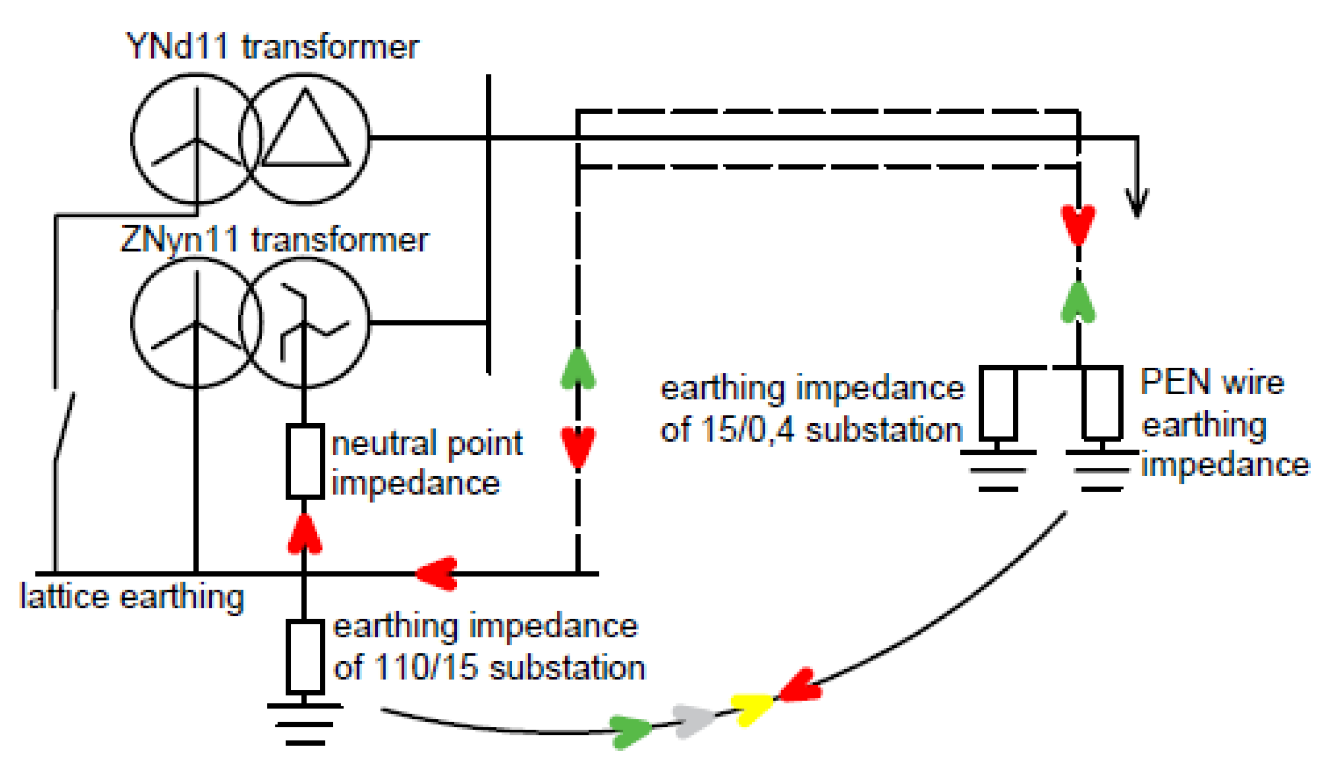
2. Zero Sequence Current Measurement
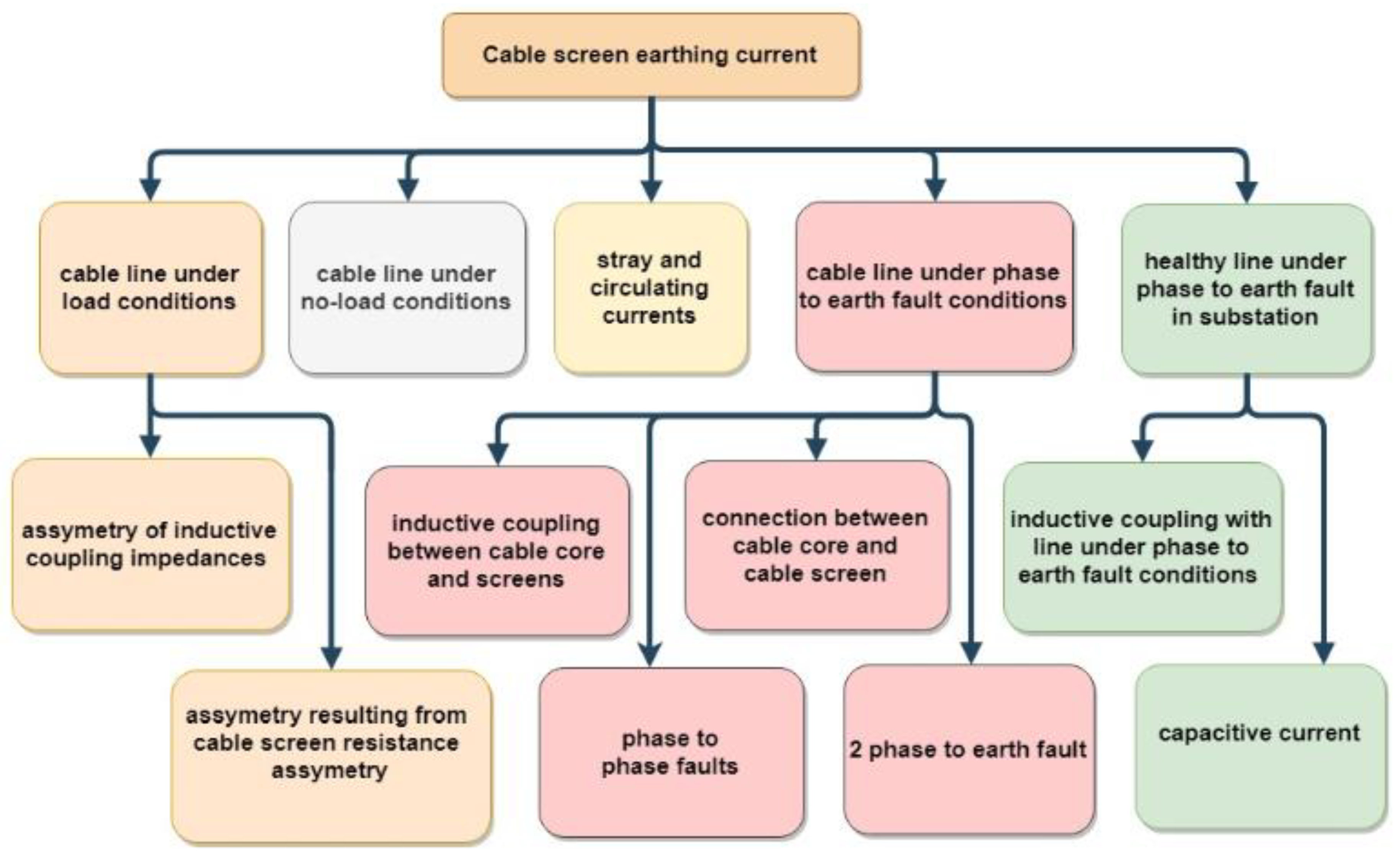
3. Cable Screen Earthing Current
4. Cable Screen Earthing Current Analysis
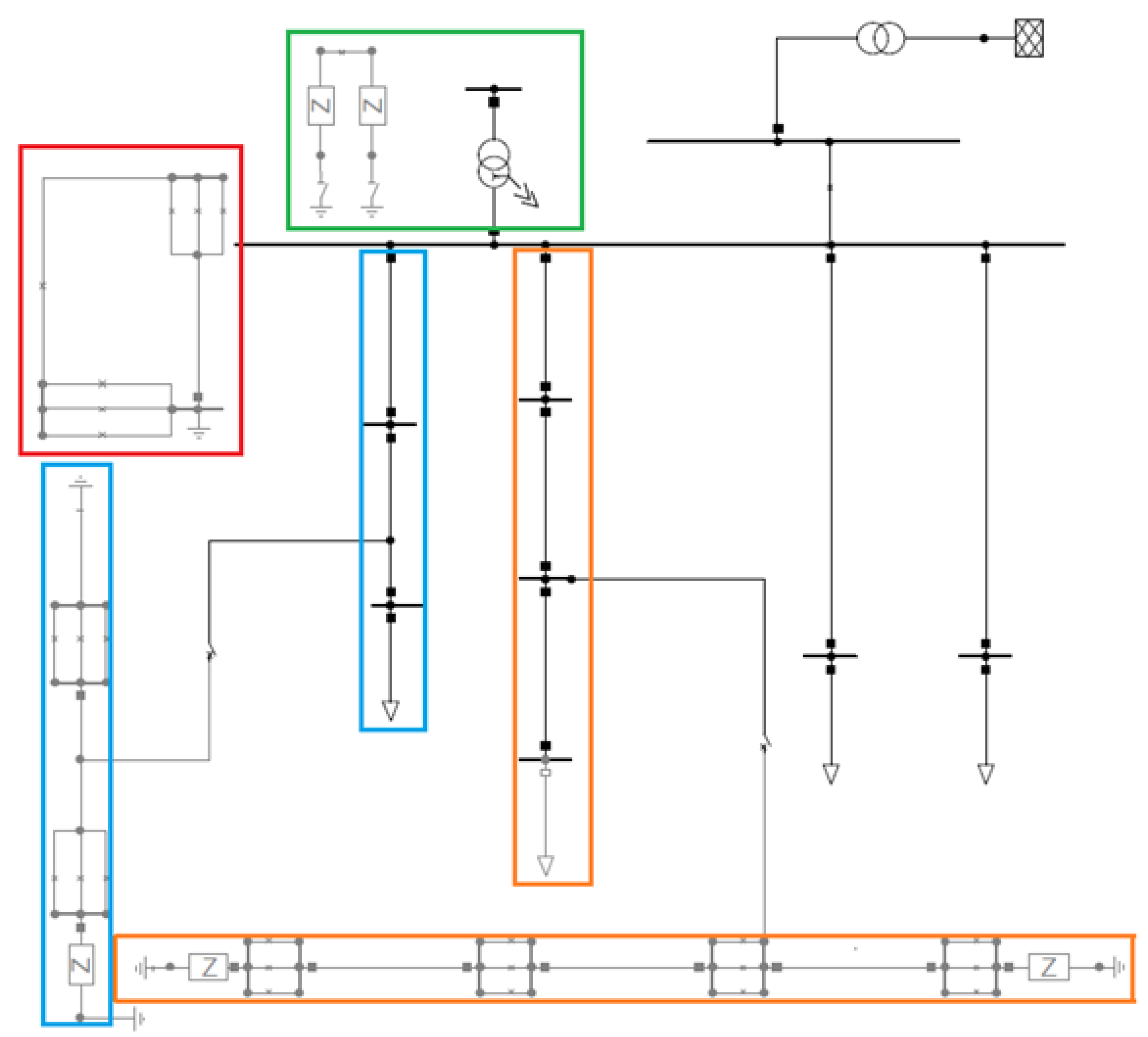
4.1. Simulation
4.2. Network Experiment
5. Results
5.1. Filtering Method
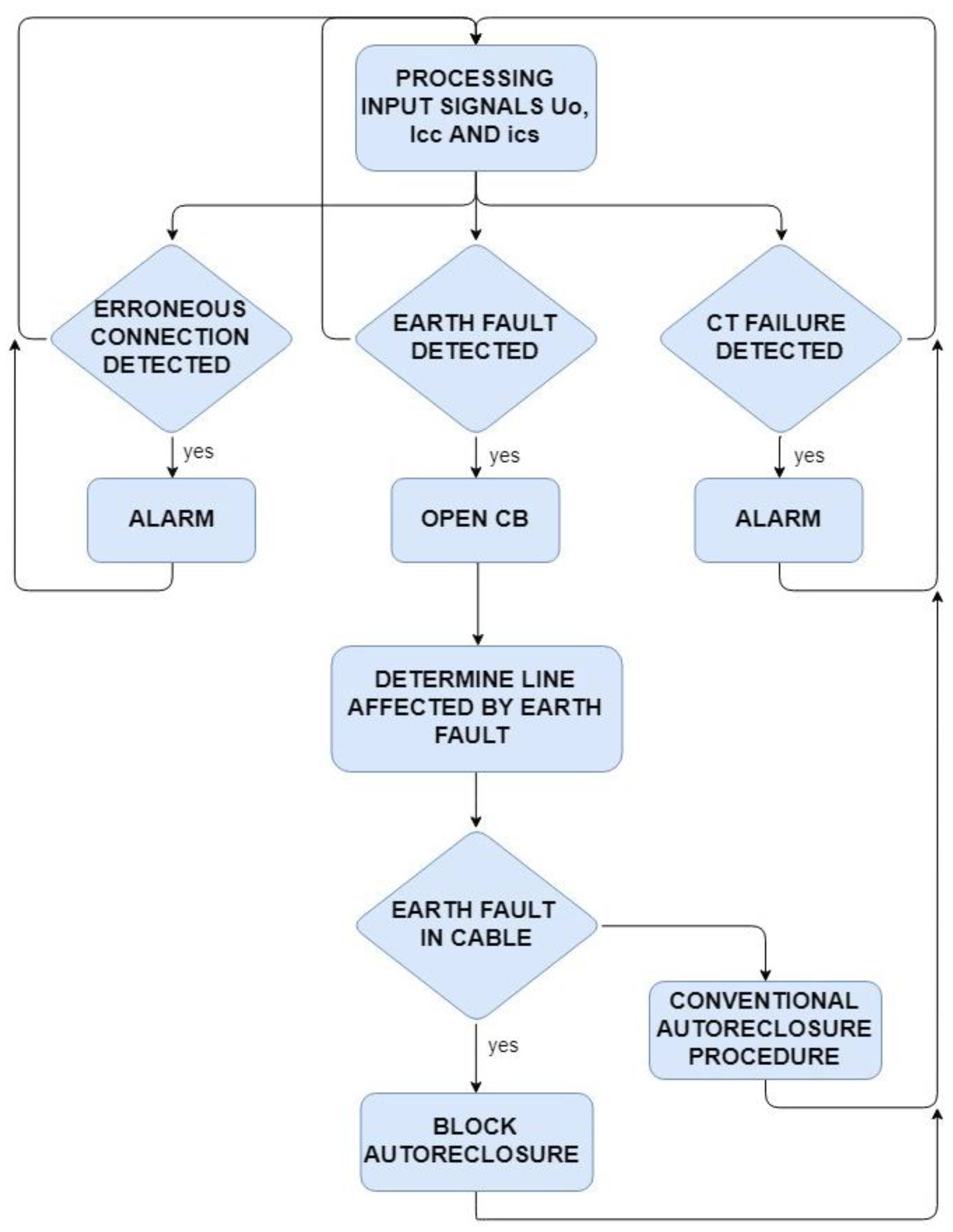
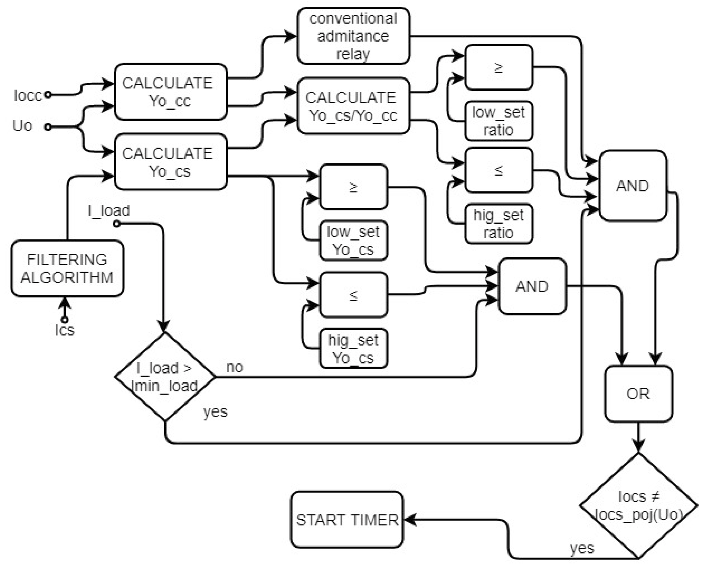
5.2. Protection Algorithm
6. Conclusions
Author Contributions
Funding
Conflicts of Interest
References
- Linkciks, J.; Baranovskis, D. Single Phase Earth Fault Location in the Medium Voltage Distribution Networks. In Proceedings of the 50th International Scientific Conference “Power and Electrical Engineering”, Riga, Latvia, 20–21 December 2018. [Google Scholar] [CrossRef]
- Makar, K. Rejestracja Zaklocen w Sieci Sredniego Napięcia; Registration of Disturbances in Medium Voltage Network. Pozn. Univ. Technol. Acad. J. 2016, 86, 189–200. [Google Scholar]
- CIRED WG03. Fault Management in Electrical Distribution Systems; CIRED: Liege, Belgium, 1998. [Google Scholar]
- Skomudek, W. Pomiary i Analiza Przepiec Oraz Ocena Ich Skutkow w Sieciach Sredniego i Wysokiego Napiecia; Measurement and Analysis of Overvoltages and Assessment of Impact on Medium Voltage Networks; Centralny Osrodek Szkolenia i Wydawnictw: Warszawa, Poland, 2011. [Google Scholar]
- Druml, G.; Kugi, A.; Seifert, O. A New Directional Transient Relay for High Ohmic Earth Faults. In Proceedings of the 17th International Conference on Electricity Distribution, Barcelona, Spain, 12–15 May 2003. [Google Scholar]
- Hoppel, W.; Lorenc, J. Dobor Nastaw Zabezpieczen w Polach Linii Sredniego Napiecia; Selection of Protection Relay Settings in Medium Voltage Bay. Autom. Elektroenerg. 2003, 2, 35–39. [Google Scholar]
- Hoppel, W.; Lorenc, J. Jak Dobierac Nastawy Zabezpieczen w Polach Funkcyjnych Rozdzielni Sredniego Napiecia; Selection of Protection Relay Settings in Bays of Medium Voltage Switchgear. Autom. Elektroenerg. 2003, 3, 43–48. [Google Scholar]
- Charlton, T.E.; Davies, M.; Baudin, D. Transfer Potentials from MV to LV Installations during an Earth Fault. In Proceedings of the 19th International Conference in Electricity Distribution, Vienna, Austria, 21–24 May 2007. [Google Scholar]
- Gustavsen, B. Study of Transformer Resonant Overvoltages Caused by Cable-Transformer High-Frequency Interaction. IEEE Trans. Power Deliv. 2010, 25. [Google Scholar] [CrossRef]
- Lorenc, J. Admitancyjne Zabezpieczenia Ziemnozwarciowe, Admittance Earth Fault Protection Realys; Wydawnictwo Politechnika Poznańskiej: Poznan, Poland, 2007. [Google Scholar]
- Yan, X.; He, Z.; Chen, W. An Investigation into Arc Selfextinguishing Characteristics on Peterson Coil Compensated System. In Proceedings of the International Conference on High Voltage Engineering and Application, Chongqing, China, 9–13 November 2008. [Google Scholar] [CrossRef]
- Zeng, K.; Zhang, Y.; Xing, L.; Wang, L. Characteristics Analysis of AC Arc Fault in Time and Frequency Domain. In Proceedings of the Prognostics and System Health Management Conference (PHM-Harbin), Harbin, China, 9–12 July 2017. [Google Scholar]
- Shirkovets, A.I. Modeling of Transient Processes at Ground Faults in the Electrical Network with a High Content of Harmonics. In Proceedings of the 2nd International Conference on Electric Power Equipment, Matsue, Japan, 20–23 October 2013. [Google Scholar] [CrossRef]
- Lowczowski, K. Wplyw Odksztalcenia Napiecia Na Przepiecia Ziemnozwarciowe; Impact of voltage distortions on overvoltage during phase to ground fault. Prz. Elektrotechniczny 2018, 10. [Google Scholar] [CrossRef]
- Hoppel, W.; Lorenc, J. Kryteria Decyzji i Funkcje EAZ w Cyfrowych Systemach CZIP.; Decision Criteria and IED functions in Digital Protection Relay CZIP. Mech. Autom. Górnictwa 1999, 10, 21–25. [Google Scholar]
- Wahlroos, A.; Altonen, J.; Uggla, U.; Wall, D. Application of Novel Cumulative Phasor Sum Measurement for Earth-Fault Protection in Compensated MV-Networks. In Proceedings of the 22nd International Conference on Electricity Distribution, Stockholm, Sweden, 10–13 June 2013. [Google Scholar] [CrossRef]
- Chroboczek, P. Kryteria Detekcji Zwarc Doziemnych o Charakterze Przerywanym w Kompensowanych Sieciach Srednich Napiec; Criteria for Detection of Intermittent Earth Faults in Compensated MV Networks. Poznan. 2004. Available online: http://www.sep.krakow.pl/nbiuletyn/nr58ar1.pdf (accessed on 20 August 2019).
- Lorenc, J.; Marszalkiewicz, K.; Andruszkiewicz, J. Admittance Criteria for Earth Fault Detection in Substation Automation Systems in Polish Distribution Power Networks. In Proceedings of the 14th International Conference and Exhibition on Electricity Distribution, Birmingham, UK, 2–5 June 1997. [Google Scholar] [CrossRef]
- Lorenc, J.; Łowczowski, K.; Staszak, B. Earth Fault Protection Supported with Adaptive Admittance Criteria. Prz. Elektrotechniczny 2018, 8. [Google Scholar] [CrossRef]
- Druml, G. Detecting High-Ohmic Earth Faults in Compensated Networks. In Proceedings of the International Symposium, Whistler, BC, Canada, 17–22 September 1995. [Google Scholar]
- CIGRE WG B5.94. High Impedance Faults; CIGRE: Paris, France, 2009. [Google Scholar]
- Wang, K.; Li, Z.; Zhang, B. A Novel Method of Power Cable Fault Monitoring. In Proceedings of the IEEE PES Asia-Pacific Power and Energy Conference, Xi’an, China, 25–28 October 2016. [Google Scholar]
- Guo, F.; Zhu, G.; Dong, X. A Method of 20 KV Cable Line Fault Location Based on Sheath Grounding Current. In Proceedings of the IEEE Industry Applications Society Annual Meeting, Dallas, TX, USA, 17–22 October 2015. [Google Scholar]
- Wang, X.W.; Song, Y.H.; Jung, C.K.; Lee, B.J. Tackling Sheath Problems: Latest Research Developments in Solving Operational Sheath Problems in Underground Power Transmission Cables. Electr. Power Syst. Res. 2007, 77. [Google Scholar] [CrossRef]
- Lowczowski, K.; Nadolny, Z.; Olejnik, B. Analysis of Cable Screen Currents for Diagnostics Purposes. Energies 2019, 12, 1348. [Google Scholar] [CrossRef]
- Dong, X.; Yang, Y.; Chengke, Z.; Hepburn, D.M. Online Monitoring and Diagnosis of HV Cable Faults by Sheath System Currents. IEEE Trans. Power Deliv. 2017, 32. [Google Scholar] [CrossRef]
- Zhou, C.; Yang, Y.; Li, M.; Zhou, W. An Integrated Cable Condition Diagnosis and Fault Localization System via Sheath Current Monitoring. In Proceedings of the International Conference on Condition Monitoring and Diagnosis, Xi’an, China, 25–28 September 2016. [Google Scholar] [CrossRef]
- Arrabe, R.G.; Gaona, C.A.P.; Gomez, F.A.; Lopez, E.R. Novel Auto-Reclosing Blocking Method for Combined Overhead-Cable Lines in Power Networks. Energies 2016, 9, 964. [Google Scholar] [CrossRef]
- Benato, R.; Dambone Sessa, S.; Guglielmi, F.; Partal, E.; Tleis, N. Ground Return Current Behaviour in High Voltage Alternating Current Insulated Cables. Energies 2014, 7, 8116–8131. [Google Scholar] [CrossRef] [Green Version]
- IEEE Substations Committee. IEEE Guide for Safety in AC Substation Grounding; IEEE Substations Committee: Scottsdale, AZ, USA, 2000. [Google Scholar]
- Hoppel, W. Sieci Średnich Napięć-Automatyka Zabezpieczeniowa i Ochrona Od Porażeń; Medium Voltage Networks—Protection Relays and Protection Against Electrical Shock; WNT: Warszawa, Poland, 2017. [Google Scholar]
- Sawko, P. Impact of Secondary Burden and X/R Ratio on CT Saturation. Wroc. Univ. Technol. Fac. Electr. Eng. 2008, 1–3. Available online: http://citeseerx.ist.psu.edu/viewdoc/download?doi=10.1.1.533.8795&rep=rep1&type=pdf (accessed on 20 August 2019).
- ST sifam tinsley. Earth Leakage Relay Core Balance Current Transformer [CBCT]. Braintree, Essex. 2019. Available online: http://www.sifamtinsley.co.uk/wp/downloads/datasheets/ELR/CBCT-sifamtinsley_UK_datasheet.pdf (accessed on 20 August 2019).
- Energotest. Rodzina Przekladnikow Ziemnozwarciowych Typu IO. 2015. Available online: http://www.energotest.com.pl/media/IU_IO-15_11.pdf (accessed on 20 August 2019).
- Talaga, M.; Adrian, H.; Michał, S. Selektywne Wylaczanie Zwarc Doziemnych w Sieciach Srednich Napiec Zakladow Przemyslowych—Część I.; Selective detection of earthfaults in medium voltage networks of the industrial plants-part I. Prz. Elektrotechniczny 2014, 9. [Google Scholar] [CrossRef]
- Wahlroos, A.; Altonen, J.; Vano, P. Effect of Core Balance Current Transformer Errors on Sensitive Earth-Fault Protection in Compensated MV-Networks. In Proceedings of the 24th International Conference on Electricity Distribution, Glasgow, UK, 12–15 June 2017. [Google Scholar] [CrossRef]
- Schinerl, T. A New Sensitive Detection Algorithm for Low and High Impedance Earth Faults in Compensated MV Networks Based on the Admittance Method. In Proceedings of the 18th International Conference and Exhibition on Electricity Distribution, Turin, Italy, 6–9 June 2005; p. 122. [Google Scholar] [CrossRef]
- Marcin, H.; Grzegorz, W.; Bogdan, M.; Aleksander, L.; Zbigniew, F. HDI PCB Rogowski Coils for Automated Electrical Power System Applications. IEEE Trans. Power Deliv. 2018. [Google Scholar] [CrossRef]
- ABB. Sensor Technology-Applications for Medium Voltage; ABB: Zurich, Switzerland, 2002. [Google Scholar]
- Lisowiec, A. Wplyw Konstrukcji Cewki Rogowskiego w Technologii PCB Na Dokladnosc Pomiaru Pradu; The use of Rogowski coil manufactured in multilayer PCB technology for the measurement of emissions of harmonic currents. Prz. Elektrotechniczny 2014, 7. [Google Scholar] [CrossRef]
- Lumiker. Optical Sheath System; Underground Cable Sheath Currents Monitoring System; Lumike: Bizkaia, Spain.
- Józef, D.; Zygmunt, K. Ograniczenie Prądów Błądzących Przez Rozdzielnie Uziomów Systemu Energetyki Zawodowej Od Energetyki Kolejowej, Tramwajowej i Metra; Reduction of Stray Currents via Separation of Earth Electrodes of Power System Utilities and Earth Electrodes of Railway Power System. Wiadomości Elektrotechniczne 2017, 4. [Google Scholar] [CrossRef]
- Van Weas, J.; van Riet, M.; Provoost, F.; Cobben, S. Measurement of the Current Distribution Near a Substation during a Single Phase to Ground Fault. In Proceedings of the 17th International Conference on Electricity Distribution, Barcelona, Spain, 12–15 May 2003. [Google Scholar]
- Popovic, L.M. Efficient Reduction of Fault Current through the Grounding Grid of a Substation Supplied by an Overhead Line. IEEE Trans. Power Deliv. 2000. [Google Scholar] [CrossRef]
- Norouzi, A. Open Phase Conditions in Transformers Analysis and Protection Algorithm. In Proceedings of the 66th Annual Conference for Protective Relay Engineers, College Station, TX, USA, 8–11 April 2013. [Google Scholar] [CrossRef]
- Kulkarni, S.; Allen, A.; Lee, D.; Chopra, S. Waveform Characterization of Animal Contact, Tree Contact, and Lightning Induced Faults; Waveform Characteristic of Underground Cable Failures. In Proceedings of the IEEE PES General Meeting, Apollis, MN, USA, 25–29 July 2010. [Google Scholar]
- Deng, J.; Zhang, W.; Yang, X. Recognition and Classification of Incipient Cable Failures Based on Variational Mode Decomposition and a Convolutional Neural Network. Energies 2019, 12, 2005. [Google Scholar] [CrossRef]
- Steennis, F.; Wagenaars, P.; van der Wielen, P.; Wouters, P.; Li, Y.; Broersma, T.; Harmsen, D.; Bleeker, P. Guarding MV Cables On-Line: With Travelling Wave Based Temperature Monitoring, Fault Location, PD Location and PD Related Remaining Life Aspects. IEEE Trans. Dielectr. Electr. Insul. 2016, 23, 1562–1569. [Google Scholar] [CrossRef]
- Tauron Dystrybucja. Standard Techniczny Nr 11/2015 Budowy Układów Uziomowych w Sieci Dystrybucyjnej; Technical standard nr 11/2015 Construction of Earthing System in Distribution Network: Poland. 2017. Available online: http://weny.pwr.edu.pl/fcp/BGBUKOQtTKlQhbx08SlkTUAxQX2o8DAoHNiwFE1xVSHlaFVZpCFghUHcKVigEQUw/38/public/rozwoj_kadry_naukowej/postepowania_awansowe/hablitacje_wnioski/habrych/zalacznik_3_-_autoreferat_.pdf (accessed on 20 August 2019).
- Byrne, T. Humidity Effects in Substations. In Proceedings of the Petroleum and Chemical Industry Conference Europe, Amsterdam, The Netherlands, 3–5 June 2014. [Google Scholar] [CrossRef]
- IEEE. IEEE Guide for Bonding Shields and Sheaths of Single-Conductor Power Cables Rated 5 KV through 500 KV; IEEE Std 575; IEEE: Piscataway, NJ, USA, 2014. [Google Scholar]
- Popovic, L.M. Improved Analytical Expressions for the Reduction Factor of Feeding Lines Consisting of Three Single-Core Cables. Eur. Trans. Electr. Power 2007, 18. [Google Scholar] [CrossRef]
- Hoshmeh, A.; Schmidt, U.A. Full Frequency-Dependent Cable Model for the Calculation of Fast Transient. Energies 2017, 10, 1158. [Google Scholar] [CrossRef]
- Fabryka Transforrmatorow w Zychlinie. Oil-Immersed Earthing Transformers; Fabryka Transforrmatorow w Zychlinie: Zychlin, Poland, 2008. [Google Scholar]
- Olesz, M.S.R. Dobor Przekroju Zyl Powrotnych w Kablach Sredniego Napiecia; Sizing of Cable Screen Cross-Section in Medium Voltage Networks. In Proceedings of the Gdanskie Dni Elektryki, Coastal, Poland, 26–28 October 2017. [Google Scholar]
- Elspec. G4K Fixed Power Quality Analyzer Blackbox User & Installation Guide; Elspec: Caesarea, Israel, 2013. [Google Scholar]
- Elspec. Pure BB Three Phase User Manual; Elspec: Caesarea, Israel, 2017. [Google Scholar]
- Rada Techniczna Enea Operator. Elektroenergetyczne Linie Napowietrzne Sredniego Napiecia; Medium Voltage Overhead Lines: Poland. 2017. Available online: https://bezel.com.pl/2018/08/01/linie-napowietrzne/ (accessed on 20 August 2019).
- Rudenberg, R. Grounding Principles and Practice-Fundamental Considerations on Ground Currents. Electr. Eng. 1945, 64, 1–3. [Google Scholar] [CrossRef]
- Fickert, L.; Malltis, T.; Ernst, S. High Current Faults in Resonant Grounded Networks under Aspects of a Global Earthing System. In Proceedings of the 23rd International Conference on Electricity Distribution, Lyon, France, 15–18 June 2015. [Google Scholar]
- Mitchel, M.; Campbell, M.; Klement, K.; Mohammad, S. Power Variability Analysis of Megawatt-Scale Solar Photovoltaic Installations. In Proceedings of the IEEE Electrical Power and Energy Conference, Ottawa, ON, Canada, 12–14 October 2016. [Google Scholar] [CrossRef]
- International Standard IEC 60502-1. Power Cables with Extruded Insulation and Their Accessories for Rated Voltages from 1 KV [Um = 1,2 KV] up to 30 KV [Um = 36 KV]. 2004. Available online: https://webstore.iec.ch/publication/2271 (accessed on 20 August 2019).
- Scottish Power. ScottishPower Distribution Cables & Equipment-Metal Theft; Scottish Power: Glasgow, UK, 2012. [Google Scholar]
- ELAND Cables. BS 5467 Copper Conductor Single Core AWA PVC BASEC 0.6/1kV Cable; ELAND Cables: London, UK, 2014. [Google Scholar]
- Chowdhury, S.; Chowdhury, S.P.; Crossley, P. Microgrids and Active Distribution Networkds; The Institution of Engineering and Technology: London, UK, 2009. [Google Scholar]
- Geid, M.; Koeppel, G.; Favre-Perrod, P.; Klock, B.; Andersson, G.; Frohlich, K. Energy Hub for the Future. IEEE Power Energy Mag. 2007. [Google Scholar] [CrossRef]
- Sperstad, I.B.; Korpas, M. Energy Storage Scheduling in Distribution Systems Considering Wind and Photovoltaic Generation Uncertainties. Energies 2019, 12, 1231. [Google Scholar] [CrossRef]
- ABB. KECA 80 C104; KECA 80 C165; ABB: Zurich, Switzerland, 2017. [Google Scholar]
- Lowczowski, K. Digital Protection Relays; Poznan, Poland. 2014. Available online: http://pe.org.pl/articles/2018/8/31.pdf (accessed on 20 August 2019).
- Wahlroos, A.; Altonen, J.; Pekkala, H.-M. Post-Fault Oscillation Phenomenon in Compensated MV-Networks Challanges Earth-Fault Protection. In Proceedings of the CIRED-Conference, Lyon, France, 15–18 June 2015. [Google Scholar]
- Granizo, R.; Blánquez, F.R.; Rebollo, E.; Platero, C.A. A Novel Ground Fault Non-Directional Selective Protection Method for Ungrounded Distribution Networks. Energies 2015, 8, 1291–1316. [Google Scholar] [CrossRef] [Green Version]
- ARCTEQ. AQ-F205 Feeder Protection Relay. Available online: https://arcteq.fi/products/aq-f205-feeder-protection-relay/?fwp_search=Poland (accessed on 10 August 2019).


| 2 Points Bonded Laid in Flat Formation | 2 Points Bonded Laid in Trefoil Formation | Single Point Bonded | 2 out of 3 Phases Unearthed | |
|---|---|---|---|---|
| Load current dependency | Average | No | No | Average |
| Dependency on erroneous connection | High | High | No | Present |
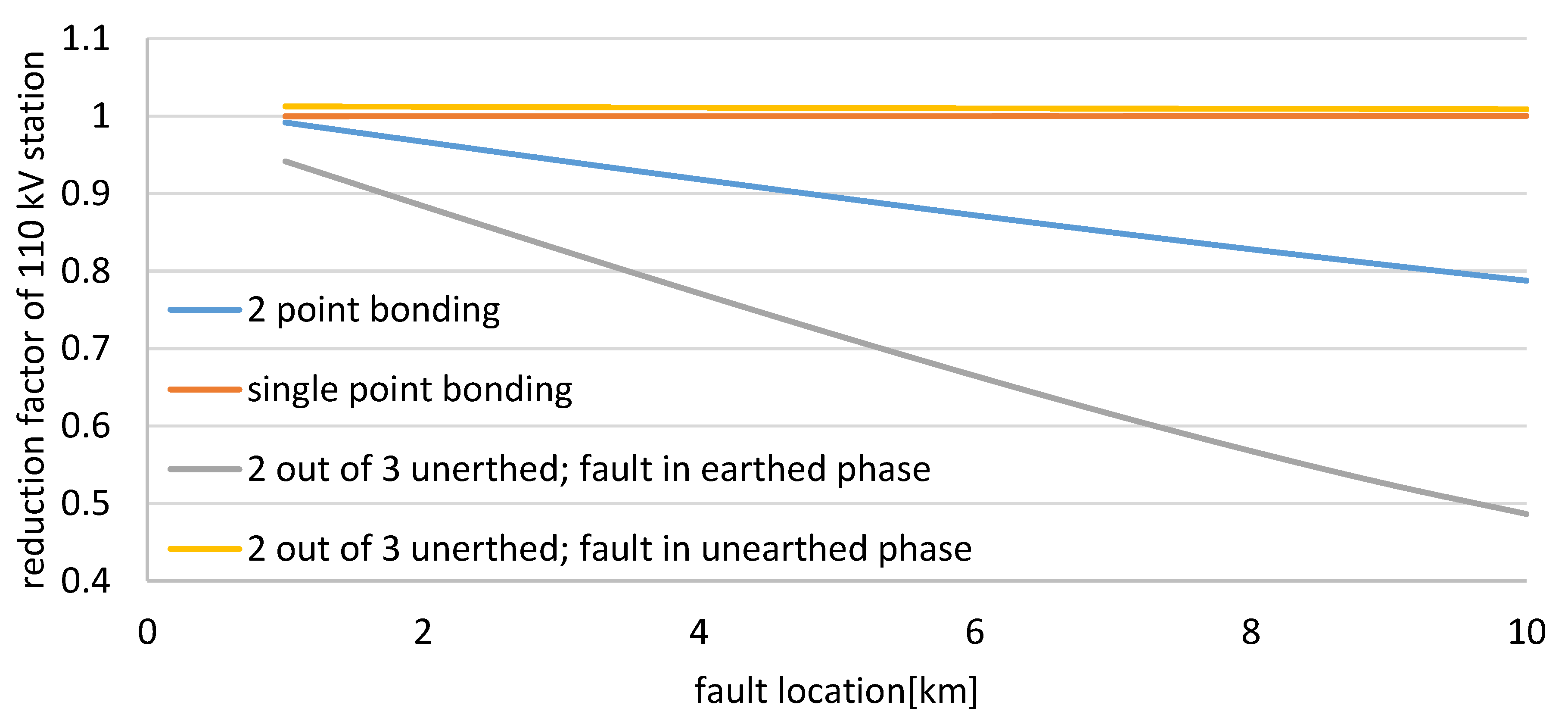
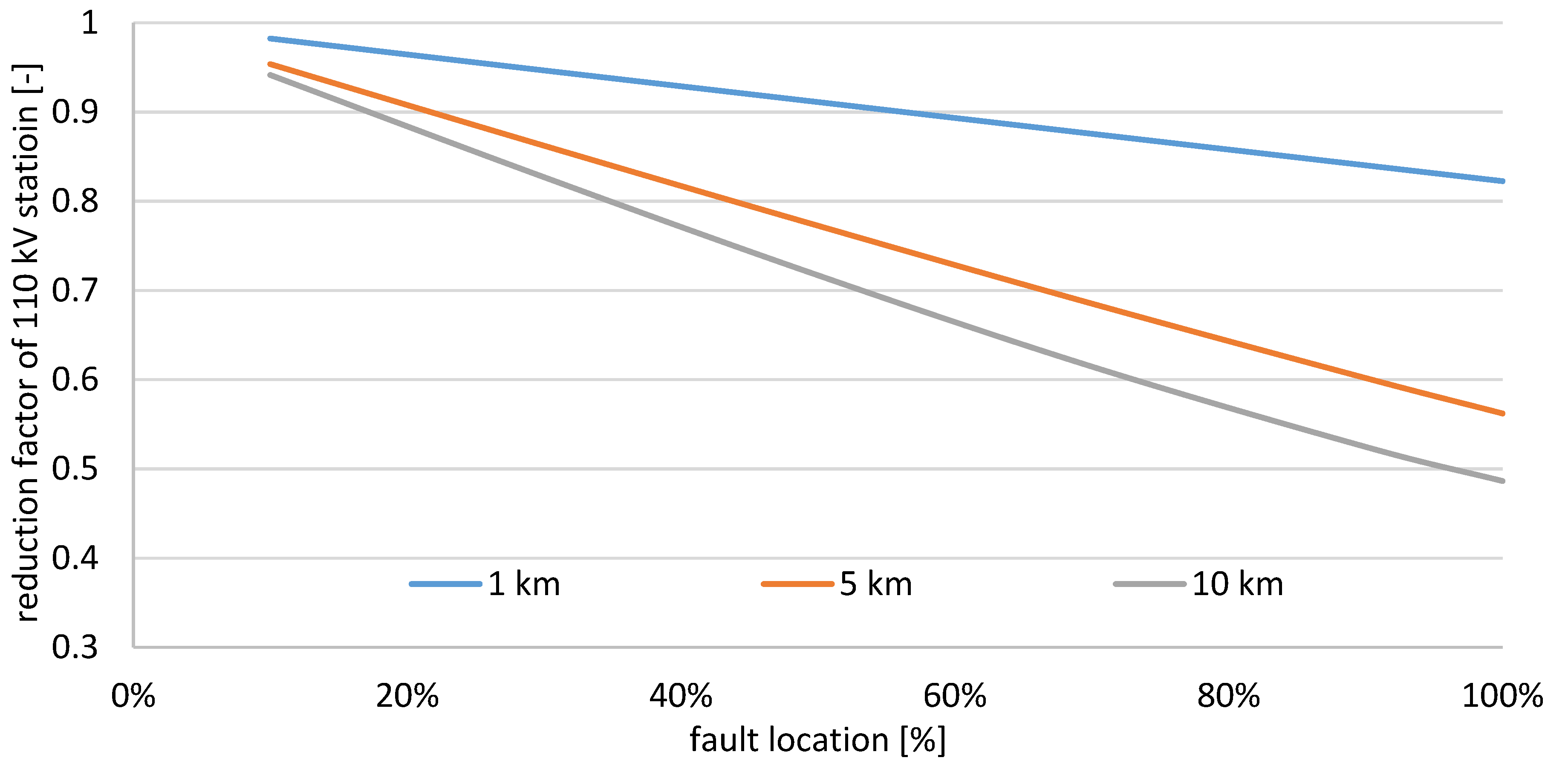
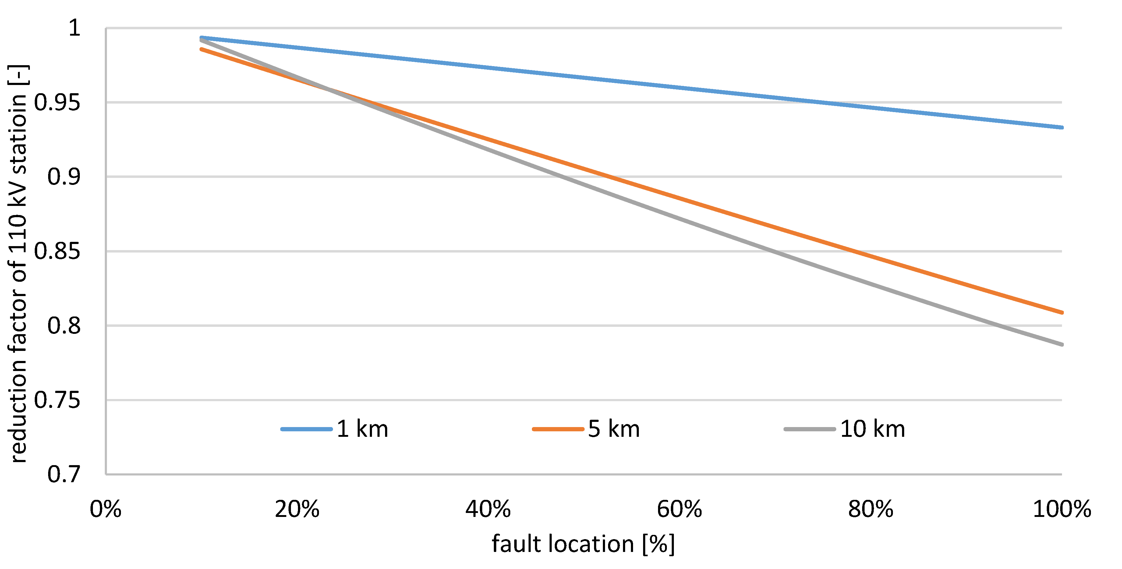
| Reduction factor of 110/15 station | High | High | High | Reduced |
| Vulnerability on stray current flow | High | High | No | Reduced |
| Inductive coupling with other lines | Possible | Possible | No | Reduced |
| Vulnerability on circulating current flow | High | High | No | Reduced |
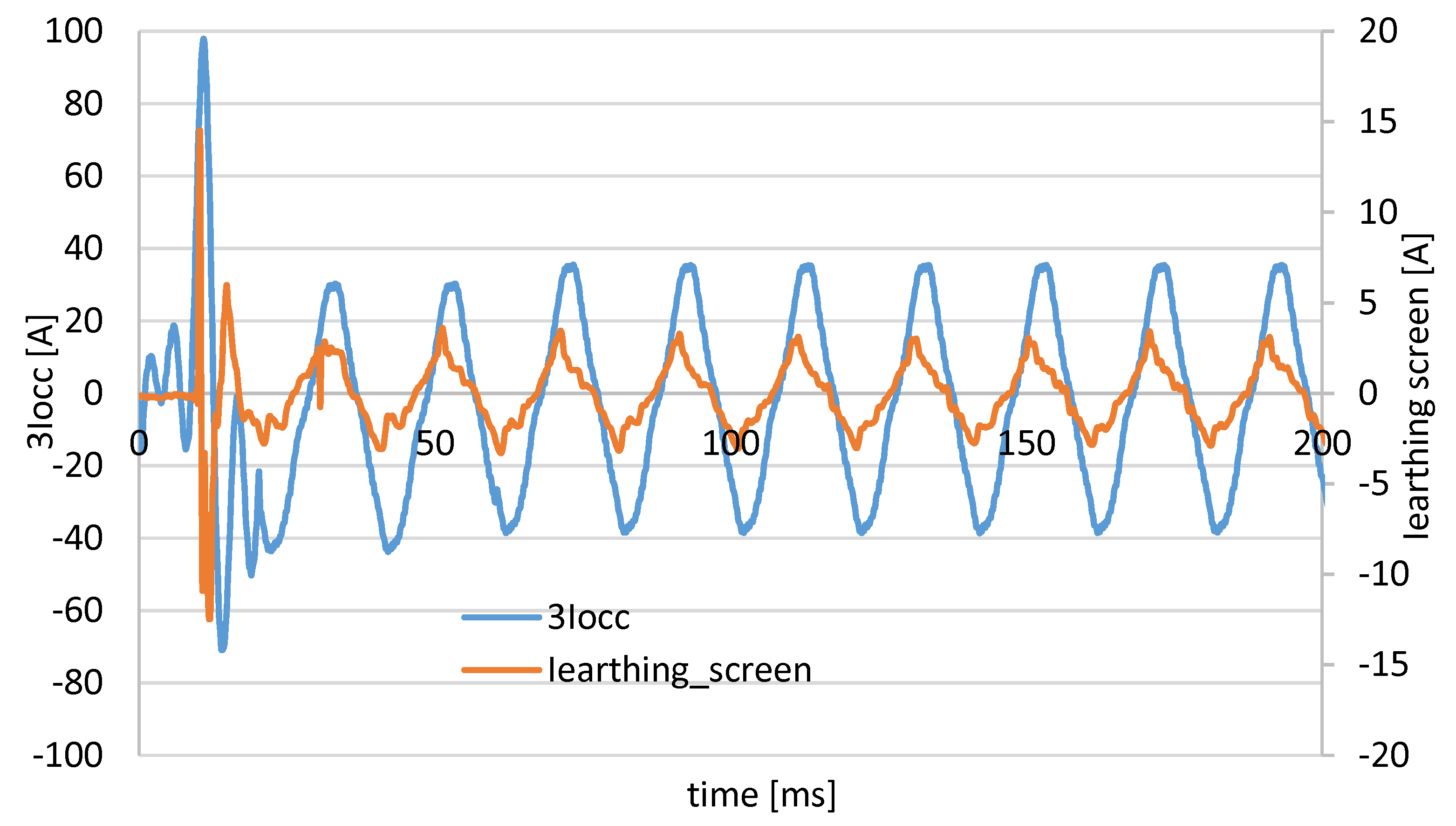
| Number of Earthed Cable Screens | Zero Sequence Core Current (I0_cc) | Zero Sequence Screen Current (I0_cs) | RF110/15 | ||
|---|---|---|---|---|---|
| Measured | Measured | Simulated | Measured | Simulated | |
| 3 | 9,1 | 8,7 | 7,7 | 0,96 | 0,85 |
| 1 | 8,8 | 6,6 | 6,1 | 0,75 | 0,69 |
| 2 | 8,9 | 7,9 | 7,1 | 0,88 | 0,80 |
| Criterion | Protection Algorithm | ||||
|---|---|---|---|---|---|
| ANSI 59N 1) | ANSI 67N 2) | I0cs/I0cc Criterion | I0cs | I0cs Filter | |
| Check wiring polarity of voltage transformer (VT) to protection system | no | yes | yes | yes | yes |
| check wiring polarity of CT’s to protection system | no | yes | yes | yes | yes |
| check tripping angle between I0 and U0 | no | yes | no | yes | yes |
| Selective tripping | no | yes | yes | yes | yes |
| Easy to set in operation | yes | no | yes 3) | yes 3) | yes 3) |
| Cost of the protection system | low | high | high | low | low 4) |
| Time to put the protection system into operation | short | long | long | long | long |
| Primary injection needed to test its functionality | no | yes | yes | yes | yes |
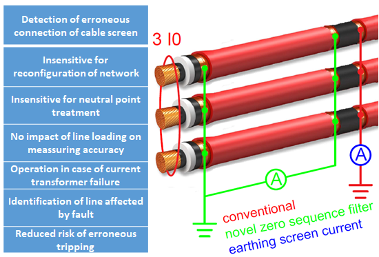
| Detection of erroneous connection of cable screen | no | no | yes | yes | no |
| Sensitive for reconfiguration of network | no | yes | no | yes | yes |
| Impact of neutral point treatment | high | high | reduced | reduced | reduced |
| impact of line loading on accuracy | high | high | reduced | reduced | reduced |
| operation in case of CT failure | CT not required | no | Reduced performance | no | no |
| Identification of line affected by fault | no | no | yes | no | no |
| Risk of erroneous tripping | yes | yes | reduced | reduced | reduced |
© 2019 by the authors. Licensee MDPI, Basel, Switzerland. This article is an open access article distributed under the terms and conditions of the Creative Commons Attribution (CC BY) license (http://creativecommons.org/licenses/by/4.0/).
Share and Cite
Lowczowski, K.; Lorenc, J.; Andruszkiewicz, J.; Nadolny, Z.; Zawodniak, J. Novel Earth Fault Protection Algorithm Based on MV Cable Screen Zero Sequence Current Filter. Energies 2019, 12, 3190. https://doi.org/10.3390/en12163190
Lowczowski K, Lorenc J, Andruszkiewicz J, Nadolny Z, Zawodniak J. Novel Earth Fault Protection Algorithm Based on MV Cable Screen Zero Sequence Current Filter. Energies. 2019; 12(16):3190. https://doi.org/10.3390/en12163190
Chicago/Turabian StyleLowczowski, Krzysztof, Jozef Lorenc, Jerzy Andruszkiewicz, Zbigniew Nadolny, and Jozef Zawodniak. 2019. "Novel Earth Fault Protection Algorithm Based on MV Cable Screen Zero Sequence Current Filter" Energies 12, no. 16: 3190. https://doi.org/10.3390/en12163190