1. Introduction
Palm oil methyl ester (PME) produced from edible sources, such as palm oil, is known as the best biodiesel in Malaysia [
1]. PME has a performance that is almost similar to diesel fuel, but with good engine emissions [
2]. However, the high density and viscosity of PME require much fuel consumption in the real-application engine. Therefore, blending PME in diesel was able to reduce the harmful emission from the diesel and improve the engine performance due to its high cetane number. However, the high density and viscosity of PME need the ethanol presence to prevent the injection system problem in the engine and reduce the fuel consumption. The reason is that ethanol has the lowest viscosity amongst diesel and PME, as explained in
Table 1. Besides, ethanol is another renewable energy fuel, promising good engine emissions. Along with the energy efficient vehicle (EEV) concept, the PME and ethanol presence can reduce the emissions, improve the engine performance, and reduce petroleum dependency.
Ethanol was recommended to be used in commercial diesel engines due to its low production cost for biofuels. Ethanol is a low viscous liquid that is able to reach good air–fuel mixture homogeneity. However, ethanol that contains a deficient cetane number reduced the engine performance and delayed the combustion [
7]. The poor ethanol ignitability is probably due to its higher evaporation enthalpy compared with diesel. Thus, the temperature was reduced during combustion due to the withdrawn heat during combustion [
8]. The long delay in combustion causes the fuel to be less combustible and forms the excess fuel in the engine. However, a perfectly blended composition should be identified to have excellent fuel combustion.
Meanwhile, high ethanol contents in blends also affect the ignitability of the fuel blends, and the excess fuel leads to fuel deposition inside the cylinder. Therefore, modification of the injection parameter was suggested to improve the ignitability of blends. Modifications of injection parameters include the injection mass, injection pressure, injection duration, and injection timing. Modification of the injection timing can improve engine performance. However, not all the applied injection strategies can solve the ignitability problem of diesel–ethanol–PME blends.
Few researchers have studied the effect of advancing the injection timing for high oxygenated alternative fuels, such as ethanol and PME. The studies found that advancing the injection timing increased the in-cylinder pressure and heat release rate (HRR). However, advancing the injection timing can increase NO
x emission [
9]. The reason is that advancing the injection timing allows the fuel to mix early and increase the temperature. Thus, the NO
x reaction takes part during the combustion easily.
Meanwhile, the presence of ethanol and PME also is another reason for the NO
x formation due to the high oxygen contents in both fuel molecules [
10]. Therefore, suitable blends of diesel, ethanol, and PME should be formed to reduce the NO
x formation. Another study was conducted in improving the ethanol ignitability by increasing the engine compression ratio. Increasing the compression ratio of the engine increases the pressure and temperature to enhance the fuel ignitability and engine efficiency [
11]. Considering that the auto-ignition temperature for the blends was high, another approach, such as increasing the ambient temperature at the intake, also helped improve the ignitability [
12]. A study from Kuszewski (2018) shows that improving the ambient gas improved the auto-ignition of diesel–ethanol blends. The results showed that the ignition delay for a high ethanol percentage is longer than that for diesel. The maximum percentage of ethanol use in this experiment is 14% [
13].
This research works aimed to study the ignitability of diesel–ethanol–PME blends and optimize the best solution in solving the non-combustible fuel blends. The non-combustible fuel blends are recognized when no ignition occurs, which usually happened on the high ethanol content blends when operating at high engine speeds. The simulation was conducted using Converge CFD software based on the direct injection Yanmar TF90 diesel engine parameter. The simulation was performed for low, medium, and high ethanol contents, containing 10% ethanol and 40% PME in 50% diesel (D50E10B40), D50E25B25, and D50E40B10 blends at 900 RPM, 1600 RPM, and 2400 RPM. The first work was to identify the non-combustible blends. The injection parameter, compression ratio, and intake temperature were modified due to the ignitability problem of high ethanol contents in the blends. The optimization of the best solution was identified from the combustion characteristic progress to solve the ignitability problem faced by high ethanol content blends.
2. Methodology
In this study, blends were simulated to analyze their ignitability and emission. Grid independence and emission tests were also conducted to determine the blend composition. The emission results from the simulation are verified with the results obtained from experimental work.
2.1. Simulation of Blends Ignitability and Emission
In this study, simulation work was conducted to analyze the combustion characteristics and emissions of diesel–ethanol–PME. The combustion characteristics analysis was used to study the combustion behavior of the fuel when entering the combustion chamber. This process includes the ignition delay, thermal efficiency, in-cylinder pressure and temperature, and heat release during combustion. This work focused on the ignitability optimization of high ethanol presence in diesel–PME blends. The simulation was conducted based on the single cylinder direct injection compression ignition Yanmar TF90 engine parameter by using Converge CFD software.
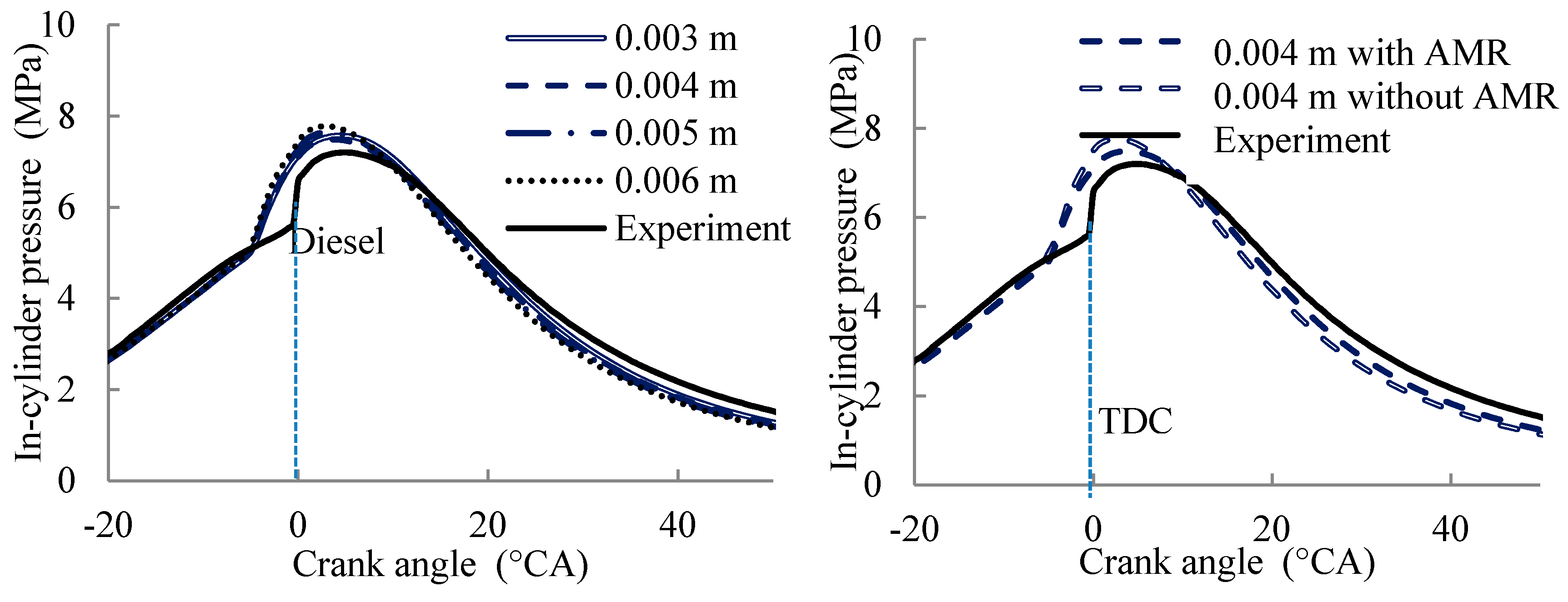
Converge CFD software is a unique software equipped with adaptive mesh refinery (AMR) with the ability to refine the mesh automatically during the combustion. A grid independence test was conducted to identify the most suitable grid size for meshing. This test aims to eliminate any unnecessary grid meshing sizes to improve simulation outcomes. The grid independence test was performed on different grid sizes of 0.003 m, 0.004 m, 0.005 m, and 0.006 m. The diesel fuel results were verified with the experiment results obtained by Ibrahim (2015) [
14]. The most suitable grid applied on the engine model is 0.004 m by activating the AMR function to allow small automatic meshing occurring during the injection and combustion.
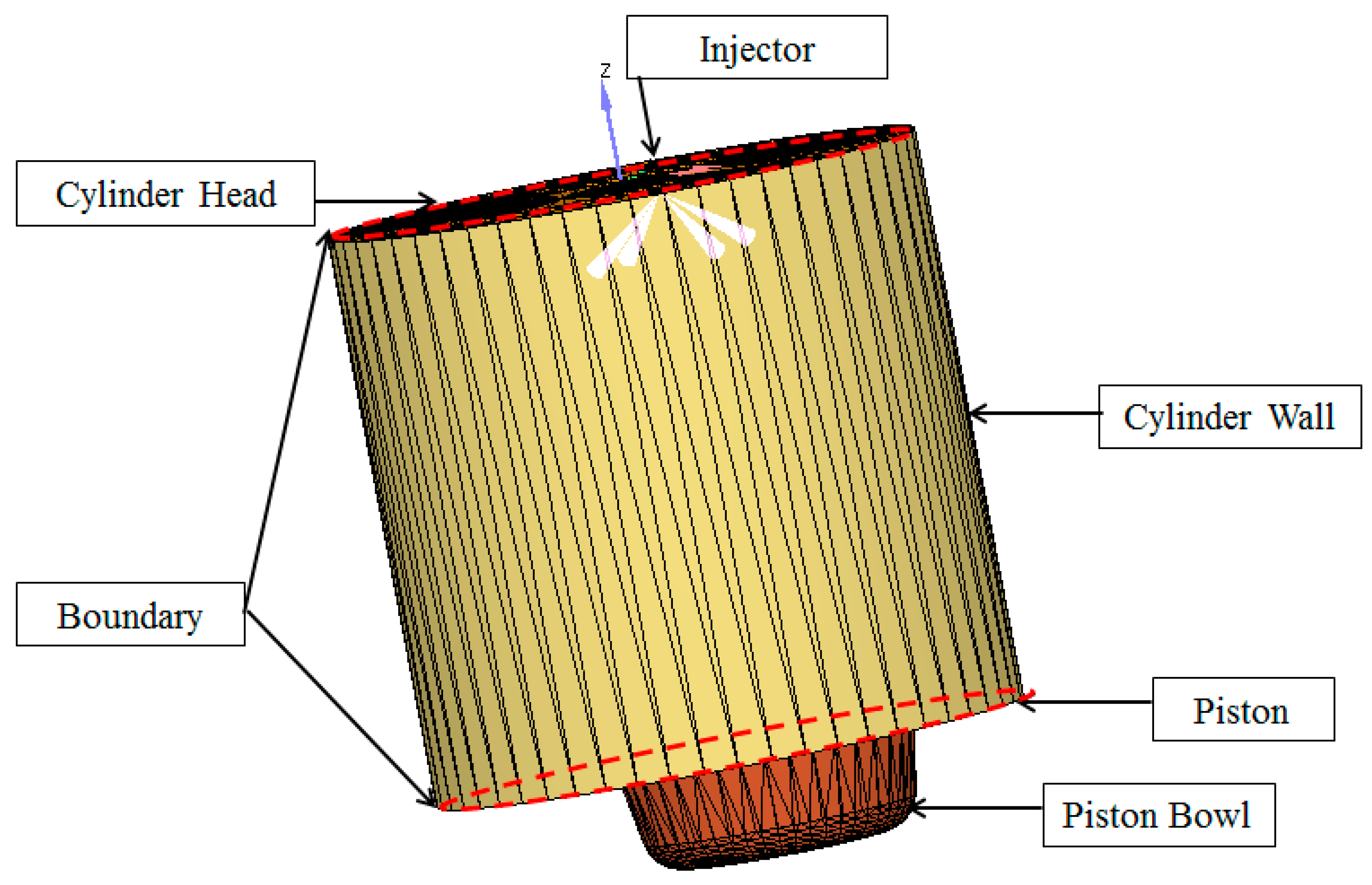
In this software, an engine model was prepared based on the engine specification, as shown in
Figure 1. The three boundaries, which consist of a piston, head, and liner of the cylinder, were assigned as the initial conditions of each boundary. The cylinder wall (liner) and head were set in a fixed position with the wall temperature of 363 K and 319 K. Meanwhile, the piston was set as a moving boundary with the wall temperature of 403 K [
15]. The parameter of the engine and injection system based on the real engine parameter for the Yanmar TF90 direct injection diesel engine was also explained in
Table 2.
The Yanmar TF90 engine is a natural aspirated air single cylinder engine with a direct injection system. The air is entered the combustion chamber at the atmospheric pressure and temperature before the piston compressed it. The simulation is conducted for a cycle starting right after the intake valve closes at −168 °CA BTDC until the exhaust valve opens at 138 °CA ATDC. The initial temperature and pressure of all the boundaries were set at the atmospheric pressure and temperature, which is 101 kPa and 300 K. The real injection timing of this engine was started at −18 °CA BTDC located at the center of the cylinder head. The combustion was simulated using a SAGE combustion model in a closed-system chamber. The mathematical correlation was solved with the text data. In this simulation, the chemical reaction, gas transport, and thermodynamic data for all the fuel blends were obtained from the Lawrence Livermore National Laboratory. Meanwhile, the chemical kinetic reaction of biodiesel underwent a mechanism reduction process to reduce the number of reactions in the data. The emission model used in this simulation was the Zeldovich NOx model, which utilizes the Hiroyasu soot model to identify emissions from combustion.
2.2. Blend Composition
A few different diesel–ethanol–PME blend compositions were applied to the engine running at 900 RPM, 1600 RPM, and 2400 RPM. The blends were injected through the injector nozzle into the engine combustion chamber. From all the blends, three blends were selected to run at 1600 RPM and 2400 RPM. The blends are D50E10B40 (50% diesel, 10% ethanol, and 40% PME), D50E25B25, and D50E40B10.
Table 3 presents the mass fraction of these blends. These blends were chosen to study the effect of ethanol and the PME presence in the engine through combustion analysis.
As explained in
Table 3, another diesel–ethanol blend named as D50E10B0 was operated and compared with the D50E10B40 blend to study the effect of PME presence in diesel–ethanol blends. Meanwhile, two diesel–PME blends such as D50E0B25 and D50E0B10 were compared with D50E25B25 and D50E40B10 to study the effect of ethanol in these two diesel–ethanol–PME blends. However, due to the presence of ethanol, which has a very low cetane number, the non-combustible blends were identified from the combustion analysis at each engine speed.
From the analysis, the non-combustible blends are then selected for a few modifications to improve its ignitability. The modifications, such as the injection system parameter, engine compression ratio, and air intake temperature, were selected. These modifications were conducted to find the most suitable modification that can be applied to improve the ignitability of the fuels. The simulation was performed at two engine speeds: namely, 1600 RPM and 2400 RPM.
Table 4 shows the modification applied to the engine by comparing the combustion characteristics from the in-cylinder pressure and HRR during combustion. From the results, the ignitability of each blend is investigated by identifying its ignition delay. Ignition delay is defined as the duration between the start of fuel injection and the start of ignition. Ignition results from the rapid rise in pressure and the occurrence of HRR. In addition, the purposes of blending the ethanol and PME in diesel are to reduce the greenhouse emission. Therefore, carbon footprint and NO
x emission analysis were also conducted from the simulation to identify the emission efficiency of each fuel blend and its modification.
2.3. Validation of Emissions from Blend Combustion through Experiments
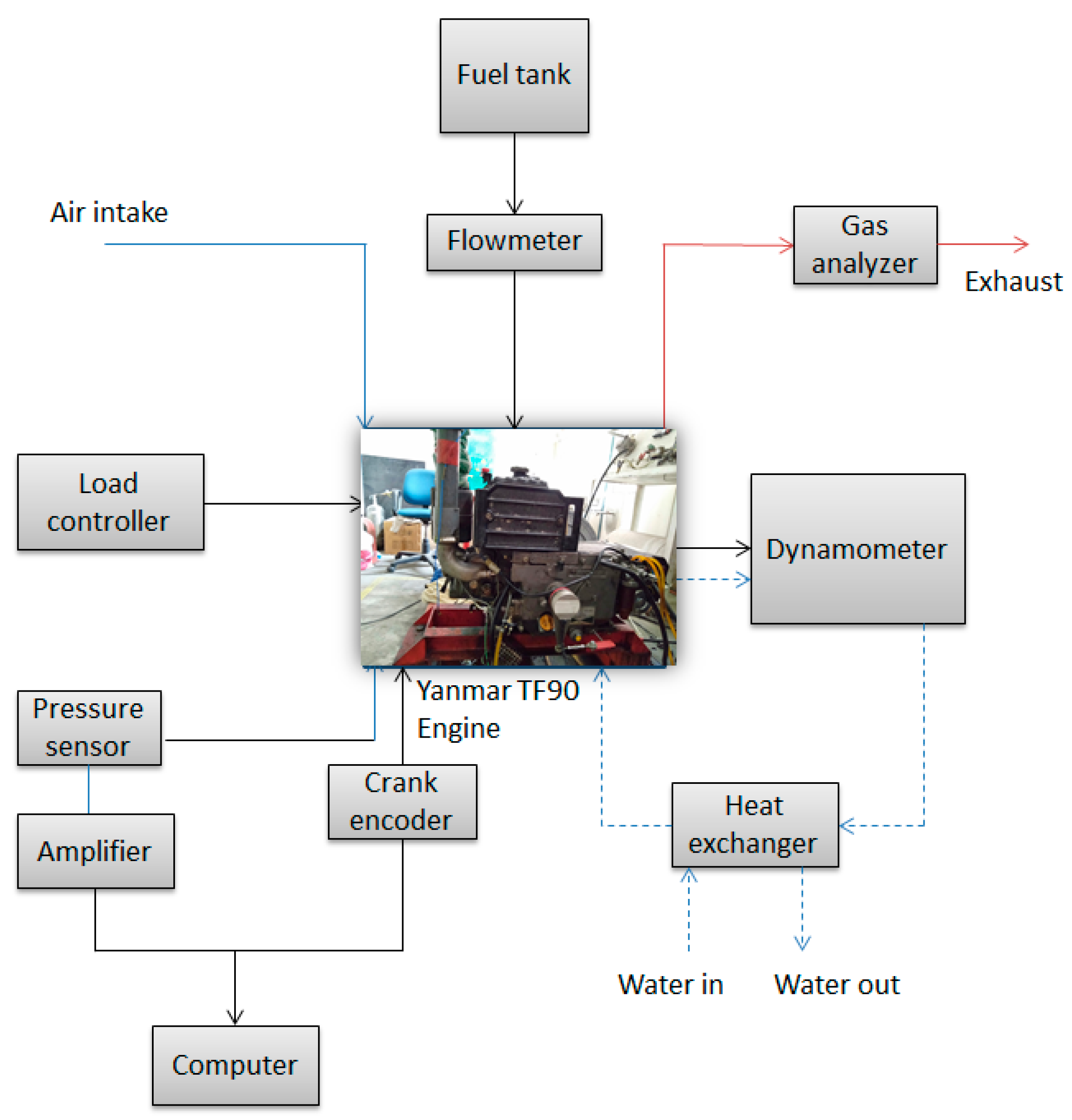
The simulation for the D50E10B40 and D50E25B25 blends was experimentally validated on the YanmarTf90 Engine.
Table 2 presents the specifications. Without any further modifications, the engine ran at 900 RPM, 1600 RPM, and 2400 RPM at a 2-kW load.
Figure 2 shows a schematic of the experiment setup. The emission of the diesel–ethanol–PME blend combustion was measured using a KANE gas analyzer, which assessed the CO, CO
2, and NO
x emissions. The limitation in this experiment is that the combustion characteristics could not be measured for validation. Therefore, the emission results from the experiment were compared with the simulation results.
3. Results and Discussion
The results of this study are focused on the ignitability of diesel–ethanol–PME blends at various compositions and engine speeds. The ignition abilities of the blends are discussed briefly for different cases especially when the blends contained high ethanol percentage. Thus, another method was applied to improve the ignition ability by working on the injection parameter change, compression ratio, and ambient temperature improvement.
3.1. Grid Independence Test
A grid independence test was conducted to identify the optimum grid size for meshing. The results of combustion characteristics were compared with the experiment results to determine the best grid size for meshing.
Figure 3 shows the in-cylinder pressure of diesel fuel from a simulation with different grid sizes compared with the experiment results when the engine is running at 1600 RPM. The grid size comparison shows that 0.004 m is the most suitable grid size for meshing, which obtains the minimum error value compared with the experiment results at the peak pressure. The comparison of data sizes and operation working durations are also part of the primary consideration.
Table 5 shows the comparison of data sizes, simulation durations, and error percentages obtained from the pressure results. A grid size of 0.004 m is the most suitable grid for further simulations.
3.2. Ignitability and Emission of Diesel-ethanol-PME Blends with High Ethanol Contents
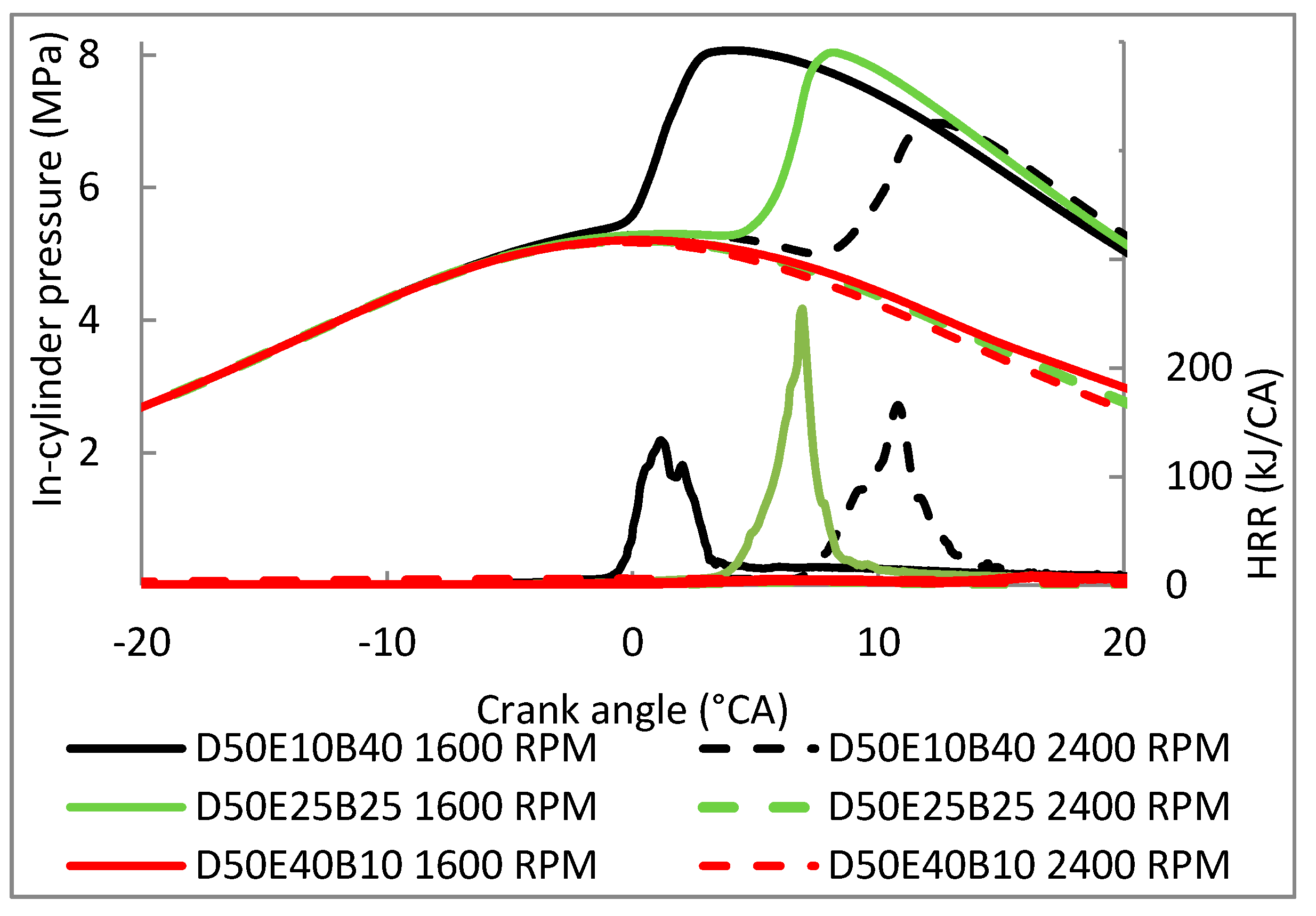
Figure 4 shows the comparison of in-cylinder pressure and HRR between the D50E10B40, D50E25B25, and D50E40B10 blends running at high engine speeds of 1600 RPM and 2400 RPM. The graph shows that the operating engine at high engine speed influenced the fuel ignitability. The result shows that at high engine speed, the ignitability of the blends weakened due to the ethanol presence that has low heating value and low cetane number. The reason is that the cetane number of ethanol was approximately five to 10 times lower than that of diesel and PME [
16]. The low heating value of the fuel also indicates that the blends release a very low heat during the compression. This condition leads to a lack of energy and delays the ignition.
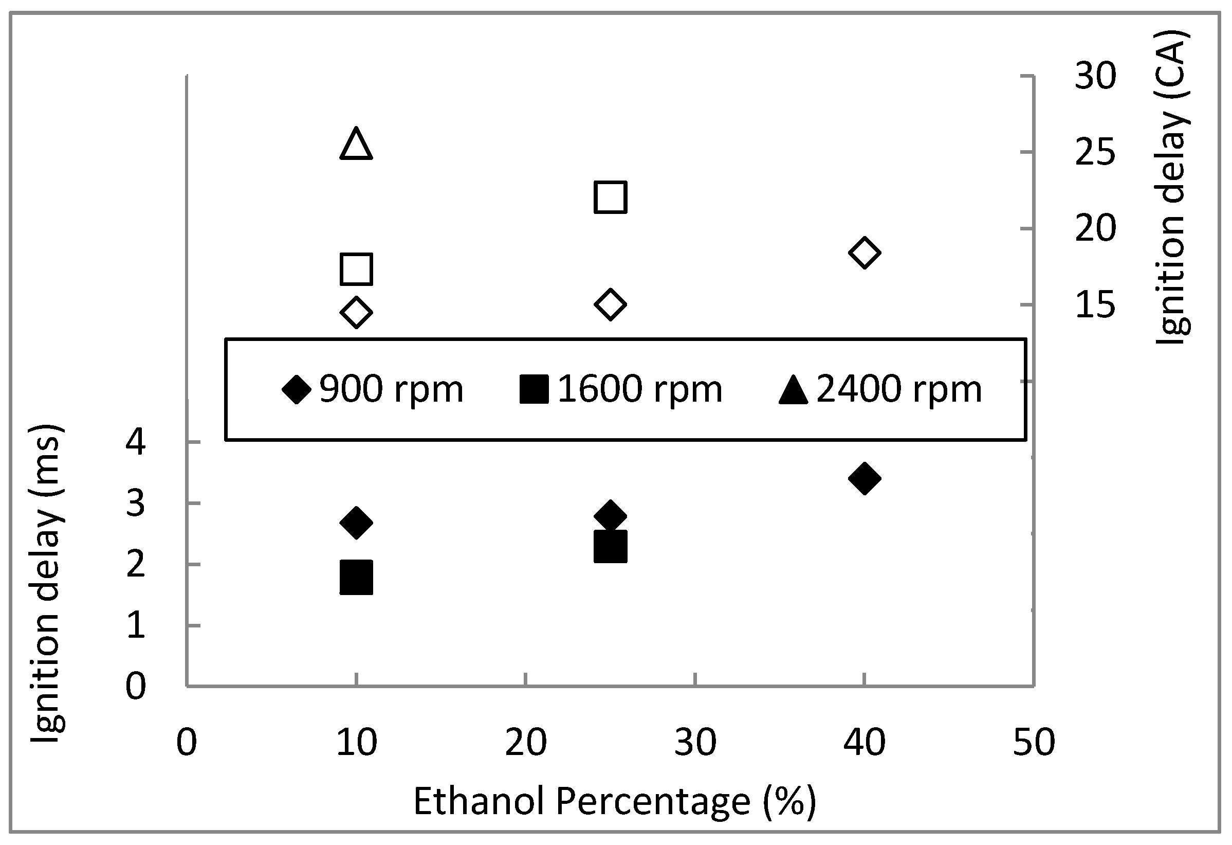
Figure 5 shows the ignition delay of the blends influenced by ethanol contents. The results show that the ignition condition is worsened when the high ethanol contents were used. Ignition delay timing in the crank angle at high engine speed is relatively lengthened, and shows opposite results in an ignition delay time in milliseconds due to the fast engine piston motion. When the engine speed moved rapidly, the engine duration to complete a cycle was shortened. This condition results in insufficient air into the cylinder and reduces the pressure in the cylinder. As presented in the graph, the D50E25B25 blend was not able to ignite when running at 2400 RPM. Meanwhile, the ignitability potential of the D50E40B10 blend was worsened at all speeds except for at 900 RPM.
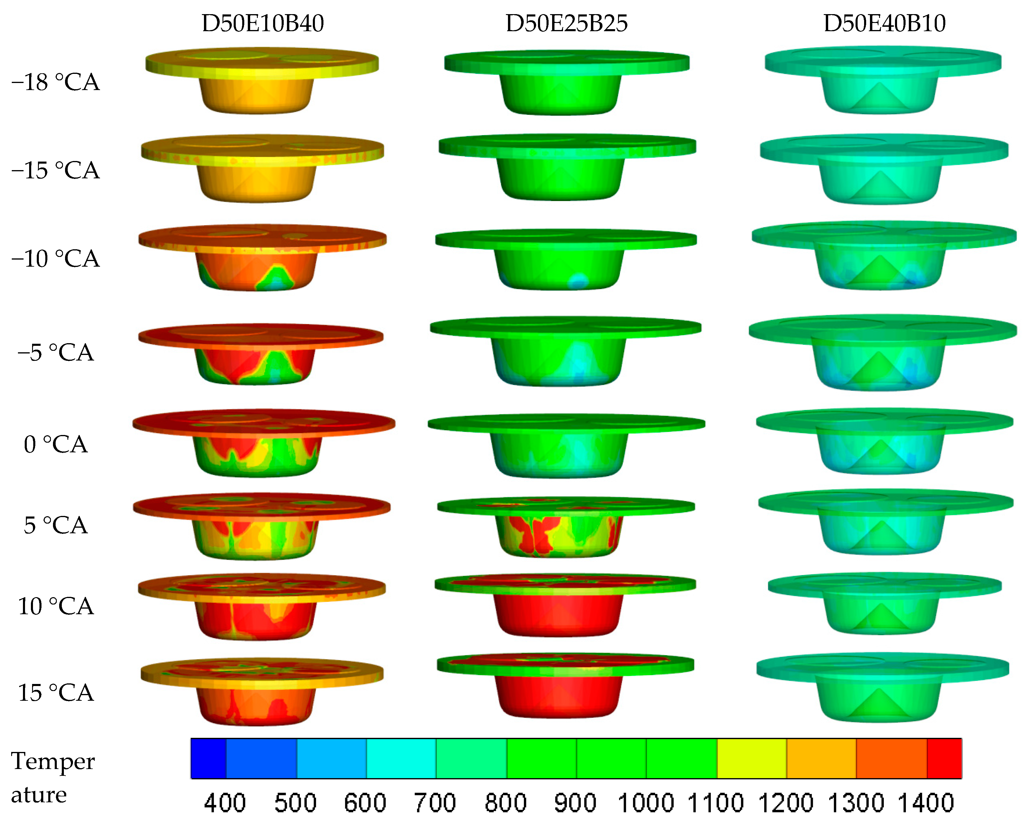
Figure 6 shows the three-dimensional (3D) visual temperature distribution for D50E10B30, D50E25B25, and D50E40B10 blends at 1600 RPM running at normal Yanmar TF90 engine specification without modification. Evidently, the high ethanol percentage in blends cannot be ignited at this engine specification due to the low ambient temperature. The maximum temperature for the blends without ignition is 850 K. This temperature is not high enough to ignite the blends with high ethanol contents. Therefore, the ignitability of ethanol present in the fuel decreases at high engine speed. However, the high ethanol contents in blends have low ignition potential and have small peak pressure due to the delay. In addition, it also has a rapid rise in HRR and small peak pressure that will cause the ignition duration. The results show that the maximum ethanol contents in the blend composition are 25% when running at 1600 RPM and are decreased when running at a high engine speed.
The emission of simulation results obtained from the combustion of all the blends is validated with the emission results from the experiment. However, due to the ignition problem faced by the D50E40B10 blend, the experiment is conducted only for D50E10B40 and D50E25B25. The average emission of CO
2, CO, and NO
x are calculated and compared to the experiment.
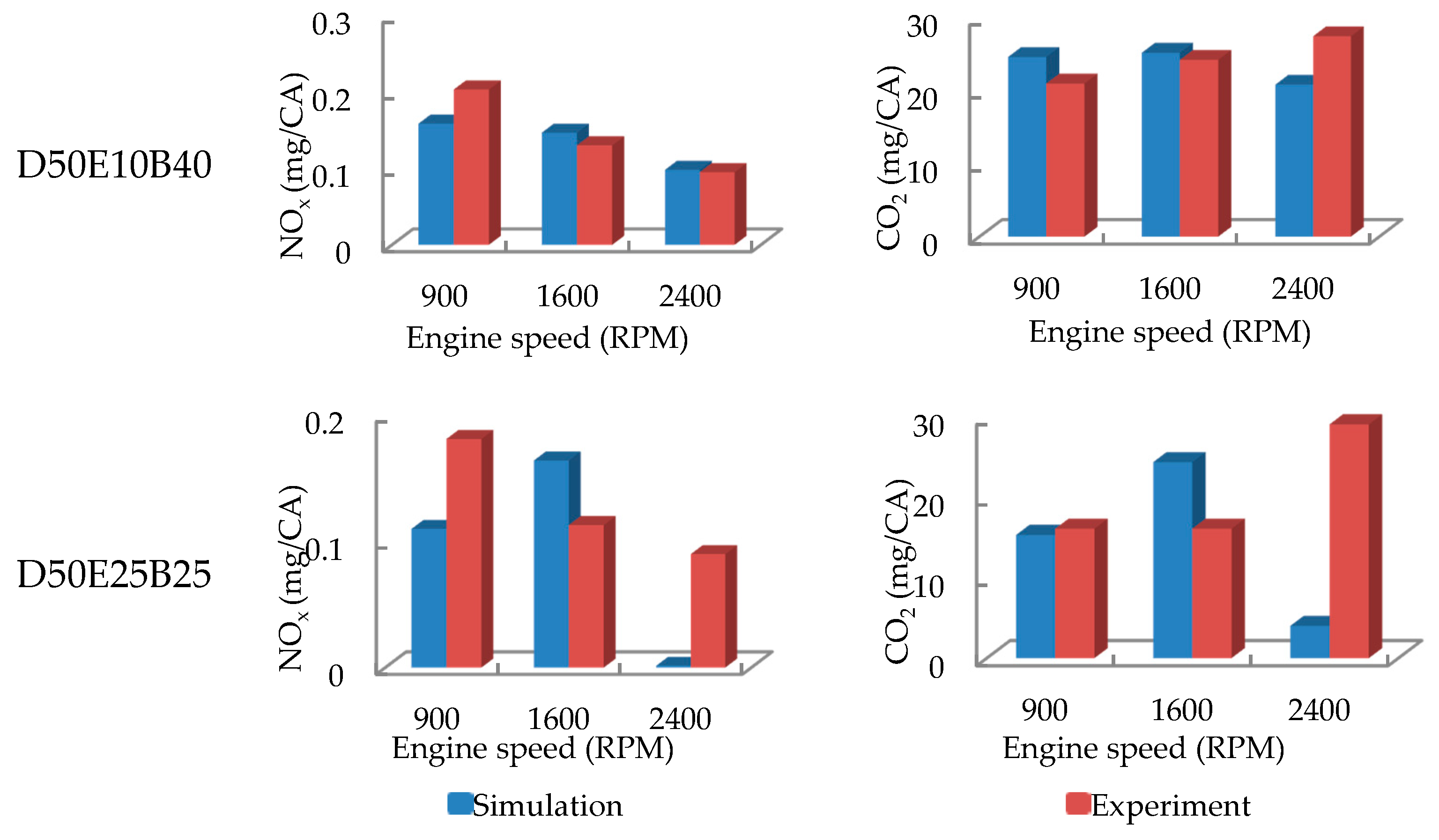
Figure 7 shows the comparison of CO, CO
2, and NO
x emissions of D50E10B40, D50E25B25, and D50E40B10 blends.
The simulation and experiment results show that the NOx and CO2 emissions of the D50E10B40 blend are insignificantly different. Meanwhile, the NOx, CO, and CO2 emissions of D50E25B25 are unstable, especially at a high engine speed. This phenomenon is due to the high ethanol contents with unstable combustion due to insufficient oxygen. The D50E25B25 blend also showed evident separation after a certain time during the experiment, which is an indication for unstable combustion. Separation occurs due to the high water presence from ethanol. Hence, diesel is probably the only fuel that can be injected into the combustion chamber. The emission results show that the simulation accuracy of the experiment has a minimum error of 5% to 30%, except for unstable combustion blends. Therefore, the simulation for the combustion characteristics and emissions of diesel–ethanol–PME blends is validated for further study.
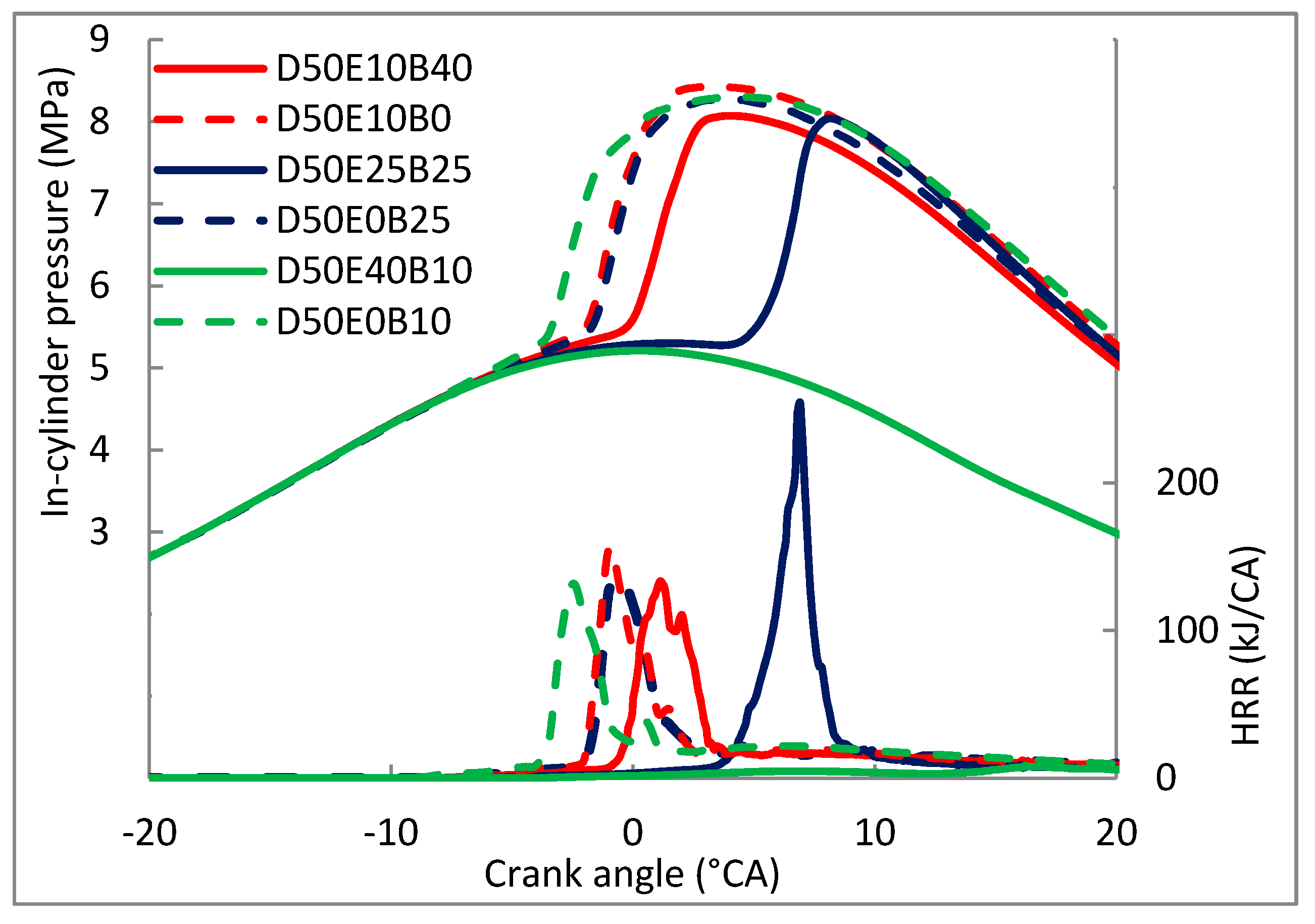
Figure 8 shows the graph of tri-fuel blends and dual-fuel blends to compare the difference of in-cylinder pressure and HRR when ethanol or PME is added. The results obviously show that the blend without any PME presence (D50E10B0) has slightly higher pressure and HRR compared with other blends. Meanwhile, the D50E0B10 blend that does not consist of any ethanol presence has shorter ignition delay and is obviously easily ignited compared with D50E40B10. This outcome is due to the biodiesel, which has a high cetane number and increased temperature to early ignite the fuel. D50E0B25 has a shorter ignition delay than D50E25B25. The diesel–PME blends without ethanol presence show a positive result to the ignition delay. Although the ignition delay of the blends with high PME contents is shortened, the HRR of the blends is very low. This condition is influenced by the properties of PME, which has high viscosity, a high molecular weight, and low burning velocity [
16]. Therefore, the presence of ethanol in D50E25B25 helps the blends obtain high HRR for improved engine thermal efficiency.
3.3. Ignitability of Diesel–Ethanol–PME Blends with Injection Parameter Modification
Injection parameters, such as injection duration, injected mass, and injection timing, were modified due to the ignition problem of the D50E25B25 blend at 2400 RPM and the D50E40B10 blend at 1600 RPM and 2400 RPM.
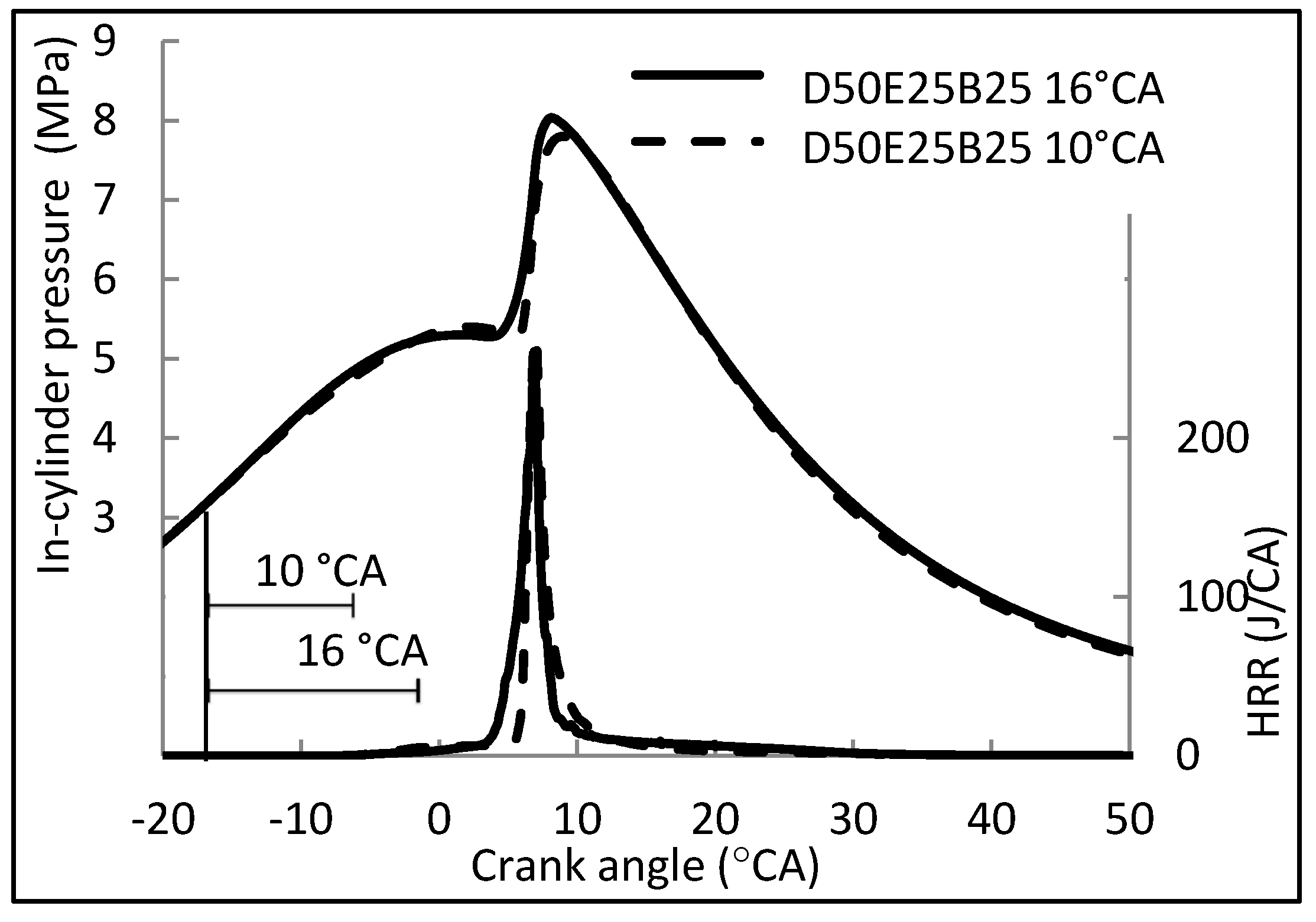
Figure 9 shows the graph of in-cylinder pressure and HRR against the crank angle of the D50E25B25 blend by using different injection durations.
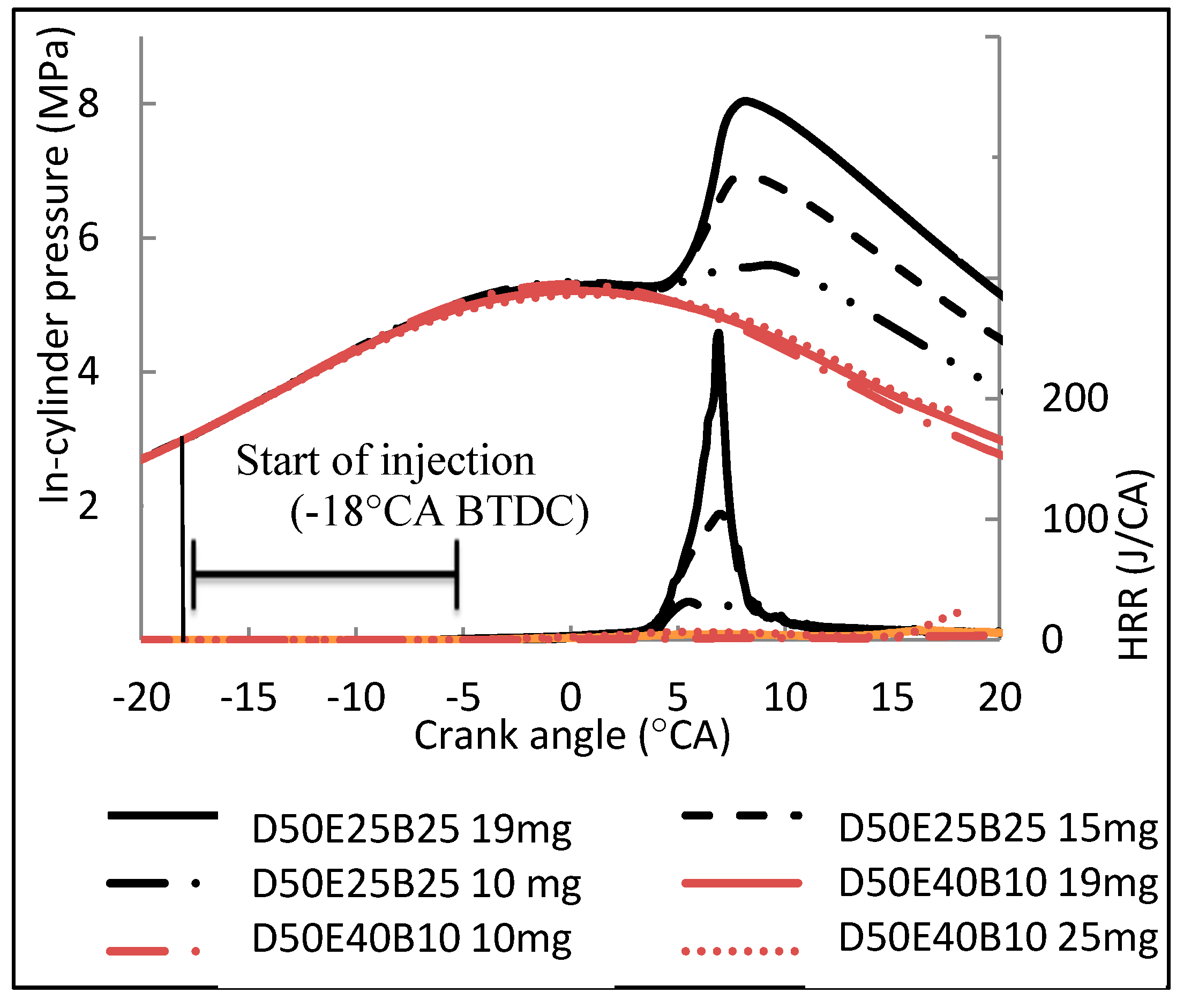
Figure 10 and
Figure 11 show the graph of pressure and HRR for the D50E25B25 and D50E40B10 blends by using different injected masses and injection timings at 1600 RPM. The result shows that modification of the injection duration has no significant change on pressure and HRR. The study from Adnan et al. (2012) also compared the injection duration of diesel but with hydrogen. They found the same trend: that no significant change is observed on the pressure and HRR for different injection durations [
17]. Furthermore, reducing the injected fuel mass also reduces fuel ignitability. Consuming a great amount of fuel to the engine for high ethanol blends does not give positive results. Therefore, the injection duration and fuel mass should be maintained with 16 °CA and 19 mg of fuel, considering that increasing the fuel amount will not meet the EEV concept.
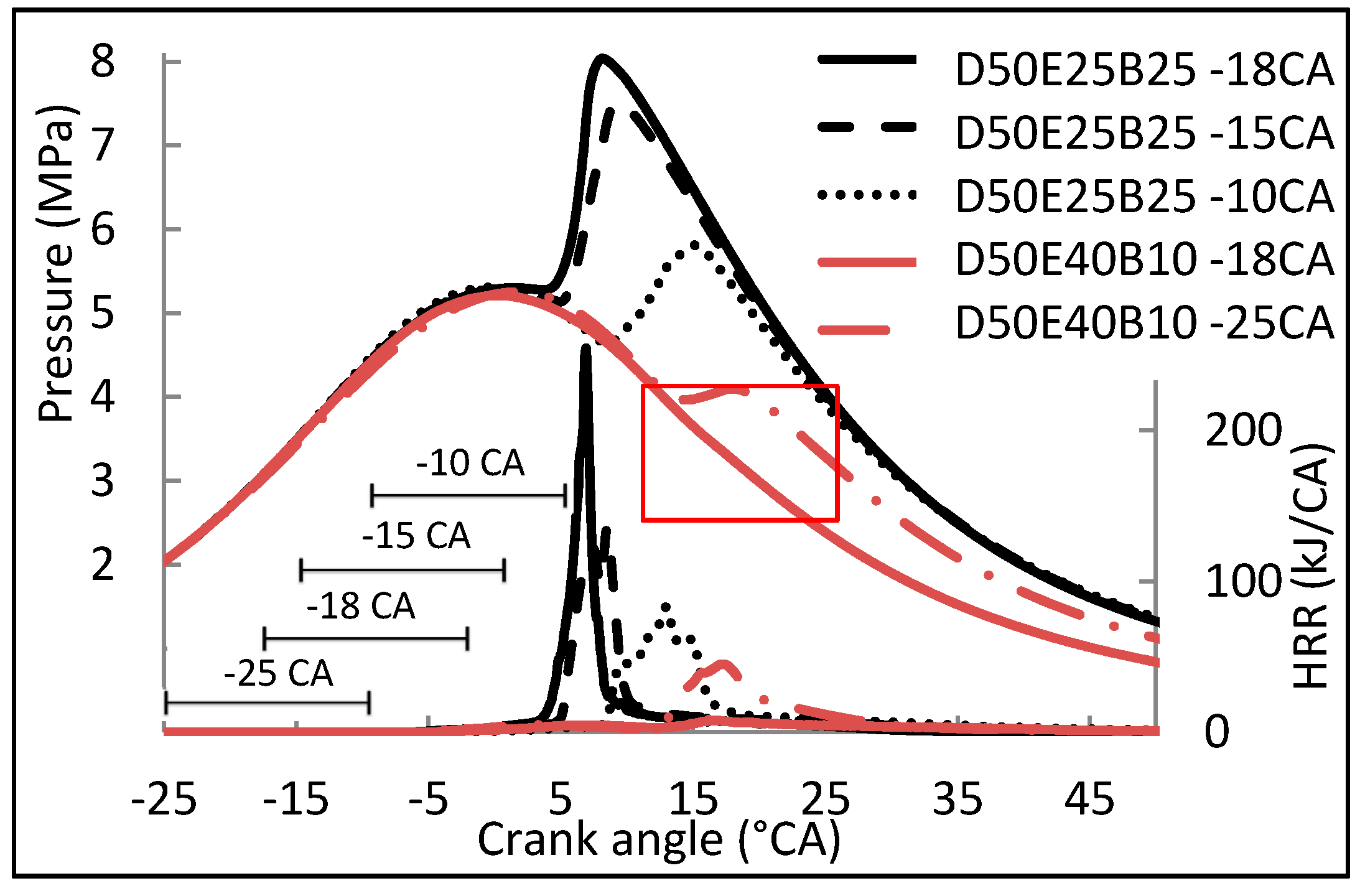
Figure 11 illustrates the pressure and HRR graph of D50E25B25 and D50E40B10 blends running at 1600 RPM with different injection times. The graph shows that advancing the injection time from −18 °CA BTDC to −25 °CA BTDC for D50E40B10 blends exhibited positive results in solving the ignition problem. However, the ignition of this fuel is very weak, as marked in the red box in
Figure 11. Meanwhile, retarding the injection timing of D50E25B25 reduced the pressure and HRR. This phenomenon proves that only advancing the injection timing can improve the blend ignitability, especially for the blends with high ethanol contents. The reason is that the advance injection can allow the fuel to be mixed early with air and increase the temperature during the premixed phase and ignite the fuel [
18]. Compared with the previous study, Mendes Guedes et al. (2018) also found that an advanced injection timing increases the pressure and HRR during combustion. In addition, the advanced ignition has a short ignition duration that is able to reduce the carbon emission problems. However, high temperature may lead to NO
x emission [
8].
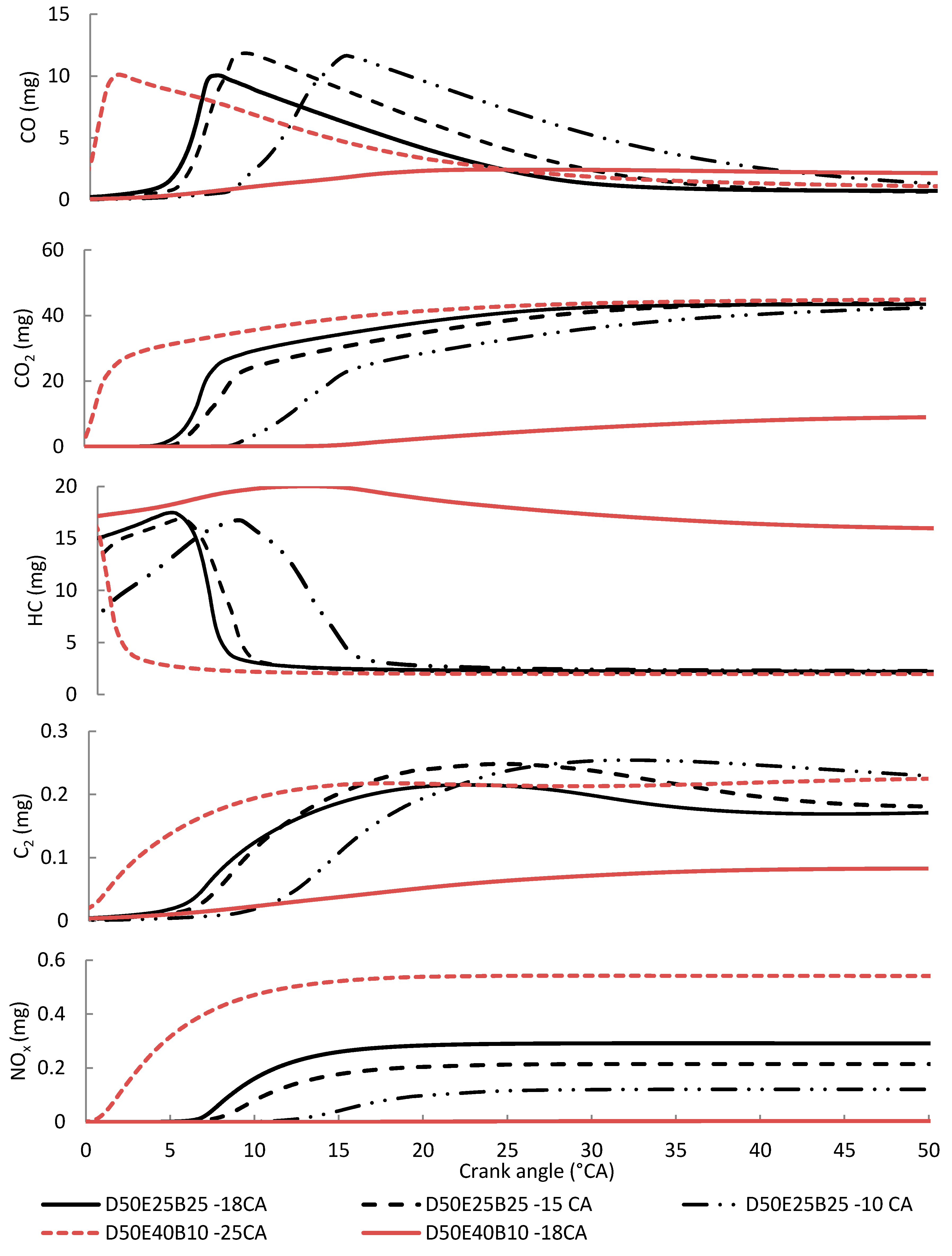
However, advancing the injection timing at the early time before the top dead center (TDC) may lead to another problem. Although advancing the injection timing improves the fuel ignitability, injecting the fuel too early can lead to the incomplete fuel combustion. Thus, the situation will increase the hydrocarbon, carbon monoxide, and soot emission. As observed in the emission graphs in
Figure 12, emissions of CO, HC, and C
2 are high with the advancement of the injection timing for the D50E25B25 blend. A few studies found that advancing the injection timing reduced the carbon emissions, while considering that the ignition started early. However, the transition of liquid fuel turning into gas is very slow, especially at high engine speeds, and leads to incomplete combustion due to the ethanol presence [
19].
Figure 12 shows the emission graphs for D50E40B10 blends with two different injection timings. Injection at −18 °CA BTDC does not have any ignition due to the high ethanol presence. Advancing the injection timing with −25 °CA BTDC was able to ignite the fuel, as shown in
Figure 8.
As illustrated in the graph, CO2, CO, and NOx emissions still occur, because the reaction between the hydrocarbon and air occurs in the combustion chamber. However, the reaction itself is insufficiently high to release additional energy for igniting the fuel, which results in a low temperature. Therefore, the ignition hardly occurs. The graph shows that the CO, CO2, C2, and NOx emissions are too low for the D50E40B10 blend without modification. The hydrocarbon (HC) emission is higher than that of the other modifications, because C and H do not completely react with other elements upon injection. No NOx emission is observed because the temperature in the cylinder is insufficiently high to trigger a reaction between nitrogen and oxygen to form NOx.
However, advancing the injection timing too early before TDC increased the emission of CO, CO2, C2, and NOx. The reason is that the fuel is injected too early before the temperature in the cylinder reaches fuel auto-ignition. In addition, high ethanol blends have a very high auto-ignition temperature. Therefore, the fuel mixture in the combustion chamber is hard to ignite. This condition will lead to a long ignition delay. Therefore, the unburned fuel in the cylinder increases and leads to incomplete combustion. The trend of emissions between D50E25B25 and D50E40B10 blends is significantly different due to the ignitability of blends at a high ethanol ratio. Moreover, advancing the injection timing earlier than −25 °CA BTDC increases the temperature before the TDC and increases the NOx emission.
3.4. Ignitability of Blends with Compression Ratio and Intake Temperature Modification
Diesel–ethanol–PME blends with high ethanol percentage faced the ignitability problem. Due to this reason, the compression ratio and intake temperature of the engine is modified.
3.4.1. Compression Ratio
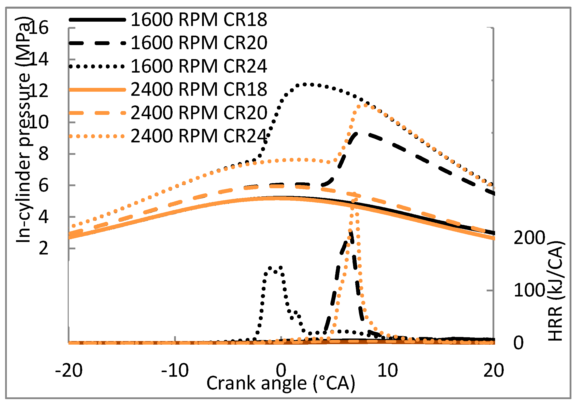
The D50E40B10 blend has significantly shown that the ignitability of this blend is very weak due to the low cetane number and delay of ignition. Therefore, compression ratio modification has been selected to improve the ignitability.
Figure 13 shows the graph of in-cylinder pressure and HRR of D50E40B10 blends operated at two different engine speeds of 1600 RPM and 2400 RPM by using various cylinder compression ratios of 18, 20, and 24. The standard compression ratio of 18 of the engine was not able to combust the fuel due to the low amount of air at high engine speed operation. Therefore, a modification of cylinder compression ratio was proved to be able to increase the in-cylinder pressure. Meanwhile, HRR decreases with the compression ratio, which is probably due to the decrease of specific energy caused by the low heating value of ethanol [
20,
21]. The reason is that the large cylinder volume is able to increase the temperature and pressure in the cylinder. High temperature and pressure in the cylinder help ignite the blends with high ethanol contents, considering that ethanol has a high auto-ignition temperature [
19].
The high engine compression ratio is also able to solve the problems of the D50E40B10 blends at high engine speed. In addition, the minimum CR allowed for the D50E40B10 blend operated at 1600 RPM is CR20, and at 2400 RPM is CR 24. A high compression ratio should be applied on high engine speed because the reaction rate is very fast and rapidly increases the pressure [
11]. However, as the CR increases, the knock and misfiring phenomenon also occur, as observed on the HRR curve. Knock occurs when the unburned fuel in the cylinder is ignited by itself before the piston reached the TDC and forced the piston to go down. Therefore, increasing the compression ratio may solve the ignition problem of the blends with high ethanol contents. However, this phenomenon leads to unwanted phenomena, such as knocking and misfiring.
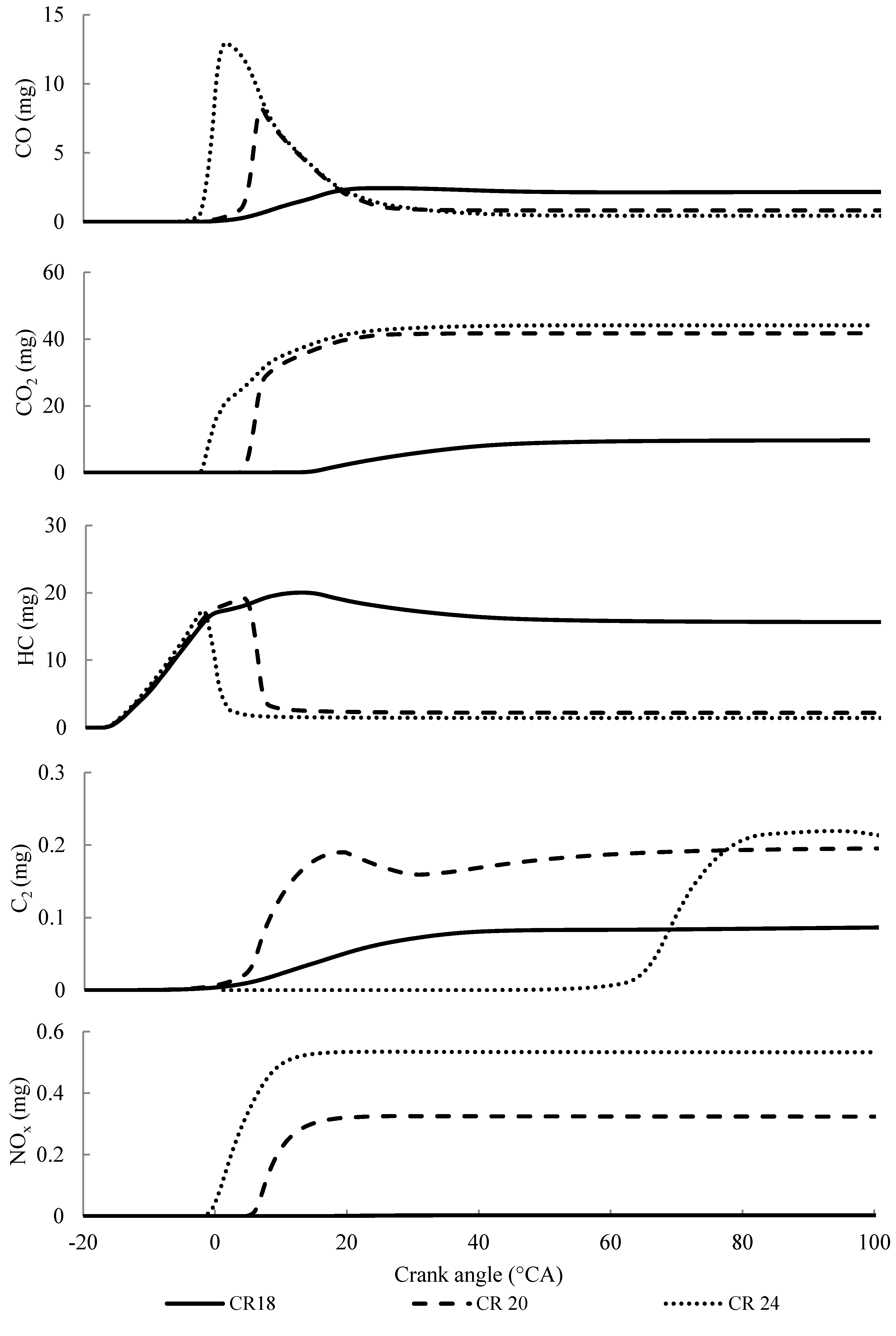
In addition, increasing the compression ratio can lead to another pollution problem.
Figure 14 shows the emission graphs of D50E40B10 blends running at 1600 RPM at different compression ratios. The results show that increasing the compression ratio increases the emission of CO
2 and NO
x emissions and reduces the CO emissions during the expansion stroke. The graphs also show that the emissions of the blends running at a normal compression ratio are too low for CO, CO
2, C
2, and NO
x emissions. This situation proves that the fuel ignition at this condition is too weak, and the reaction of hydrocarbon with air is too low. The heat release from the reaction is insufficiently high to increase the temperature for ignition.
The emission difference of CO between CR 20 and CR 24 was really significant, with a difference of approximately 55%. Meanwhile, the percentage difference of CO
2 emissions between CR 20 and CR 24 was only 5%. However, the emissions of hydrocarbon and soot for CR 24 was found to be lower than those for CR 20, because increasing the compression ratio shortened the ignition delay, and the temperature in the cylinder is high enough to combust the fuel and reduce the emissions of HC and CO. However, high temperature in the cylinder also increases the NO
x emissions [
22]. The previous study also found similar changes in emissions, wherein the high compression ratio reduces the emissions of carbon but increases the NO
x emission [
23,
24]. From the comparisons of the blends on the combustion characteristics and emissions, CR 20 is considered the best for the D50E40B10 blend at 1600 RPM, and CR 24 works well with the blend at 2400 RPM.
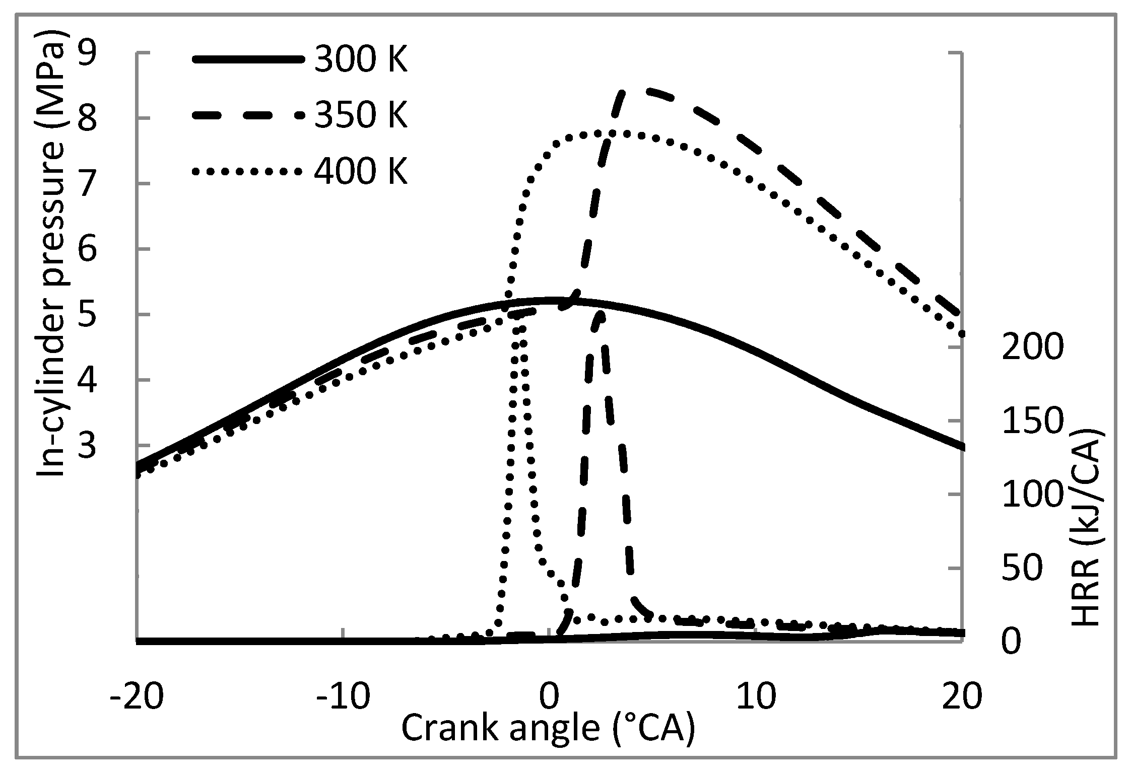
3.4.2. Intake Temperature
Another method for improving the ignitability of high ethanol content blends is by increasing the in-cylinder temperature that can be applied by increasing the temperature or air at the intake
Ti.
Figure 15 shows the in-cylinder pressure and HRR of D50E40B10 blends operated at 2400 RPM by applying different
Ti. The results show that increasing the air temperature increases the temperature in the cylinder and is able to improve the fuel ignitability. Increased
Ti ignites the fuel early, has wide combustion, and produces a great amount of heat power. However, early ignition at high engine speed can cause misfiring. In addition, burning the diesel–ethanol–PME blends at 400 K has lower in-cylinder pressure compared with that at 350 K. Studies from Akashah et al. (2015) also found that a high ambient temperature has the weakest energy and low in-cylinder pressure for ethanol combustion. This phenomenon proves that the high ethanol presence has this effect whereby it causes the in-cylinder pressure at the highest ambient temperature to decrease [
25]. Meanwhile, using 350 K of intake temperature increases the pressure rapidly and exhibits the highest peak pressure. Therefore, 350 K is the most suitable intake temperature needed to ignite the D50E40B10 blend when operating at high engine speed.
Normally, to increase the intake temperature in the real engine, an intake heating system or exhaust gas recirculation (EGR) system can be applied to the engine with the temperature rise of approximately 350 K [
7]. However, implementing an EGR should be reconsidered, because it can reduce engine efficiency. However, this process is very useful in reducing NO
x emissions. Therefore, applying the air-heating intake system is another solution in the future to control the temperature of air intake with the minimum temperature of 350 K if more than 40% ethanol in the blends is used. A patent from Linkenhoger (2005) designed an air-heating intake system to heat up the air and vaporize the fuel to improve the engine efficiency, improve the fuel economy, increase the engine power, reduce the carbon emission, and increase the engine life [
26].
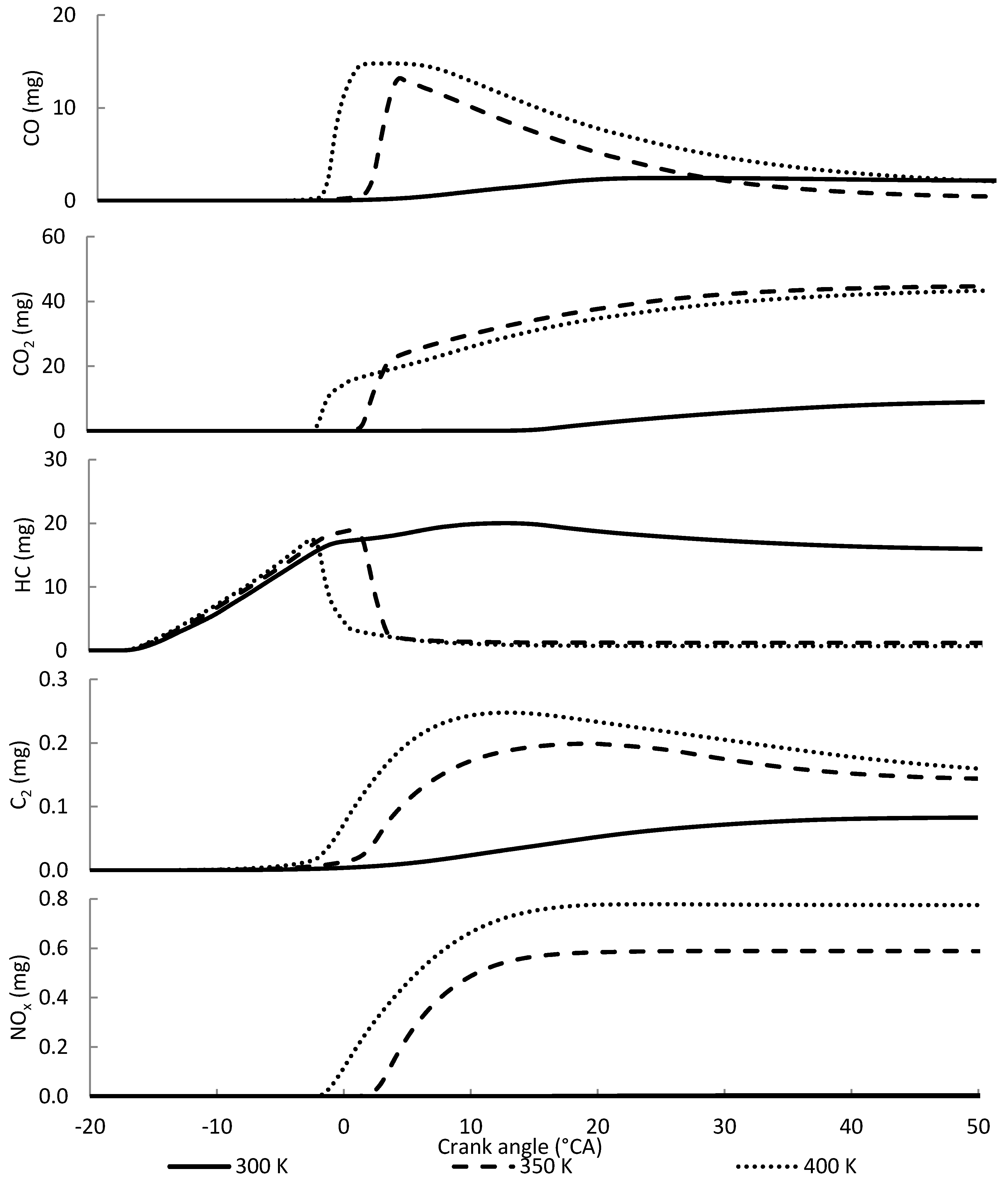
Figure 16 shows the emission results of the D50E40B10 blend at different intake temperatures running at 1600 RPM. The study found that increasing the intake temperature emits increased CO and CO
2 emissions. The NO
x emissions also increased with the increase of the temperature in the cylinder and contributed to NO
x reactions. The soot formation was also increased with the increment of intake temperature due to the shortened ignition delay [
27].
However, the hydrocarbon emissions decreased with the increased intake temperature, because the increased temperature has a good tendency to burn all the fuels that contain high ethanol contents due to the high auto-ignition temperature of hydrogen and long ignition delay. From the combustion characteristics and emission analysis, Ti = 350 K is the most suitable intake temperature to ignite the D50E40B10 blends with low emission and low effect of abnormal combustion.
3.5. Effect of Modification on Combustion Characteristics and Emissions
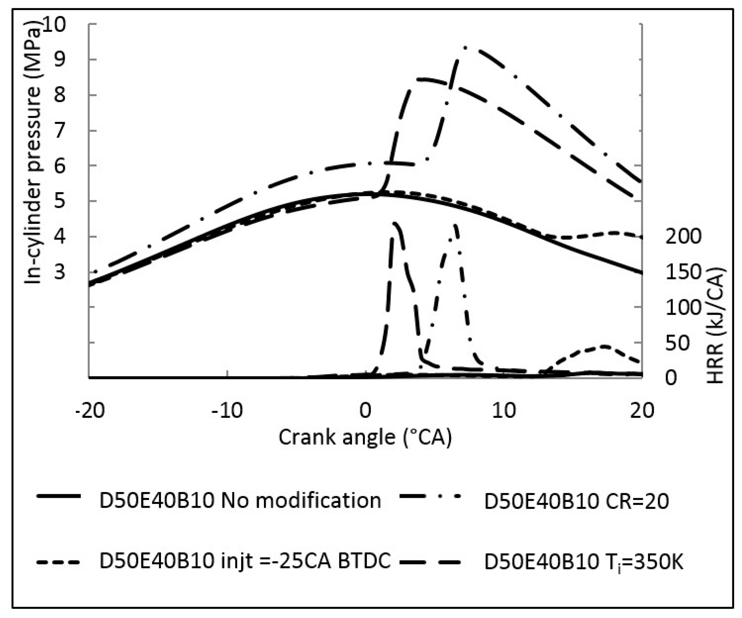
Here, we compare all the injection modifications, compression ratios, and intake temperatures in order to determine the best combustion efficiency and emissions.
Figure 17 shows the pressure and HRR graph of the D50E40B10 blends running at 1600 RPM. The results show that the compression ratio modification has a dominant effect on in-cylinder pressure and HRR. Besides, injection timing modification also gives a very small effect on the combustion, since the ignition of the blend at this condition is very weak. However, the heat rate released from the combustion for ambient temperature modification and compression ratio modification shows no significant difference except the ignition delay. Operating the D50E40B10 blend at an ambient temperature of 350 K has a shorter ignition delay than that operated at a compression ratio of 20.
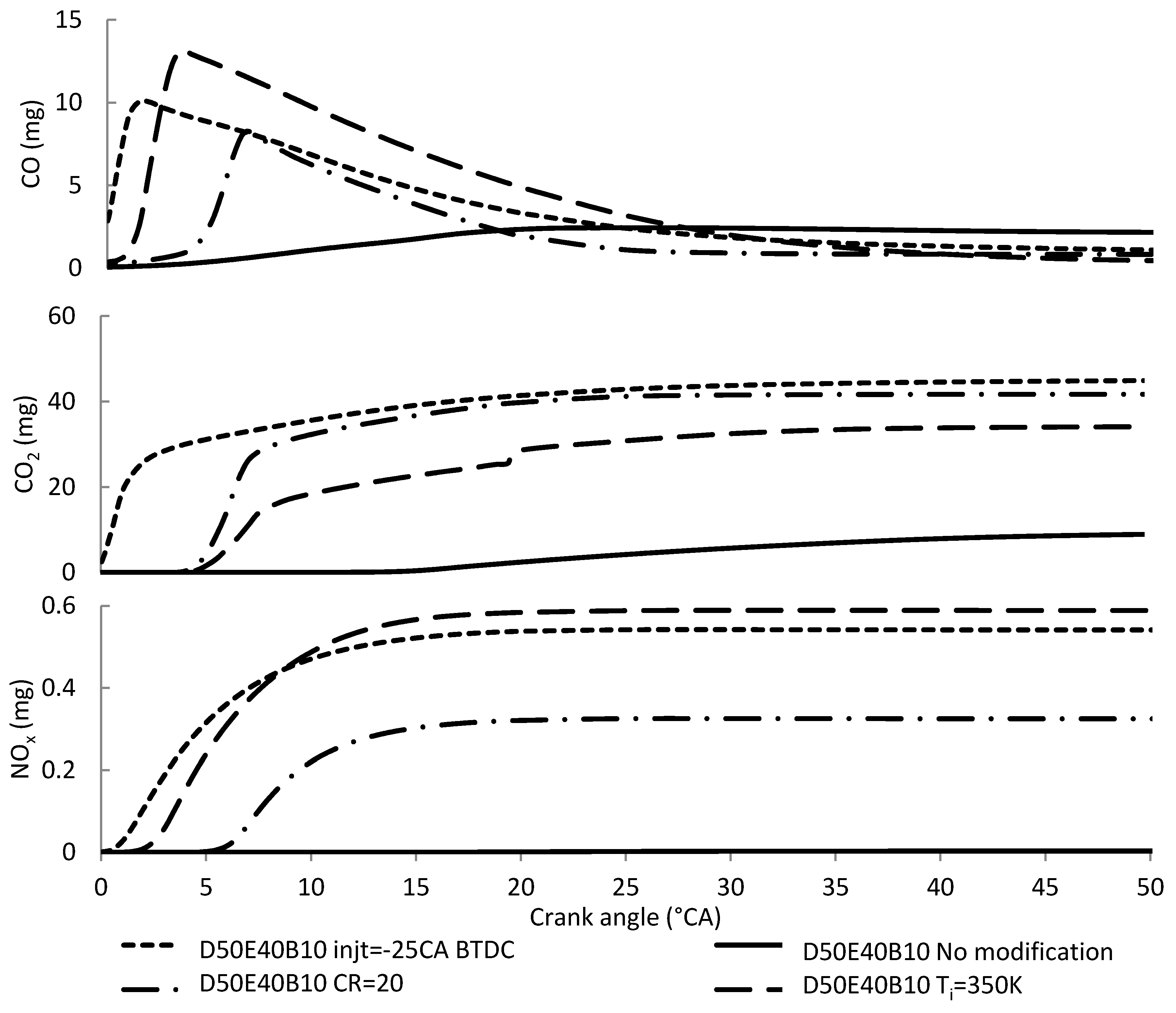
Figure 18 shows the comparison of emissions between the injection timing advancement, compression ratio, and intake temperature modification. Although the modification of engine intake temperature and compression ratio release has high HRR and pressure, the emission of this modification is severed compared with the other modifications. The graphs show that increasing the engine intake temperature increases the CO and NO
x emissions. The reason is that the high temperature from the combustion and high oxygen contents from the blends leads to the NO
x formation. Therefore, intake temperature modification was chosen as the best engine modification to solve the blend ignition problem, improve the combustion efficiency, shorten the ignition delay, and reduce the carbon emissions.
4. Conclusions
Blending diesel, ethanol, and PME in a diesel engine with different compositions results in a different ignitability behavior. Ethanol with a low heating value and low cetane number reduces the ignition ability due to the long ignition delay. A simulation study has been conducted for different diesel–ethanol–PME compositions. From the simulation, the following conclusions are drawn:
High ethanol contents reduce the ignitability of the blends, and the maximum speed achieved by D50E25B25 only at 1600 RPM and D50E40B10 was not ignited at both engine speeds.
Changing the injection duration and increasing the injected mass was not helpful enough to ignite the D50E40B10 blends at 1600 RPM and 2400 RPM. Meanwhile, advancing the injection timing at approximately −25 °CA increased the in-cylinder pressure and its HRR. Advancing the injection timing successfully ignites the fuel blends. However, the combustion was so weak, and the ignition delay was too long. Moreover, advancing the injection earlier than −25 °CA increases the NOx emission.
Therefore, modification of the compression ratio and ambient temperature produces good results in improving the ignitability of D50E40B10 blends with minimum CR20 at 1600 RPM and CR24 at 2400 RPM. Increasing the ambient temperature by implementing an air-heating or EGR system to the engine can improve the ignitability. The most suitable intake temperature for the D50E40B10 blend is 350 K, producing high peak pressure and HRR.
From the comparison between all the modifications of injection, compression ratio, and intake temperature, the most suitable modification for diesel–ethanol–PME blends is increasing the intake temperature. This procedure produces increased in-cylinder pressure and HRR, but has a short ignition delay. Although the NOx emission of intake temperature modification is slightly high, the abnormal combustion phenomena can be avoided compared with the compression ratio modification.
In the future, the heating system should be mounted to the intake to increase the air intake temperature in the real engine application. Further studies on the diesel–ethanol–PME blend ignitability on the engine performance, combustion characteristics, and emissions should be investigated and another approach to reduce the emission focusing on NOx emission should be applied.


