The Impact of Air Pressure Conditions on the Performance of Single Room Ventilation Units in Multi-Story Buildings


Abstract
:1. Introduction
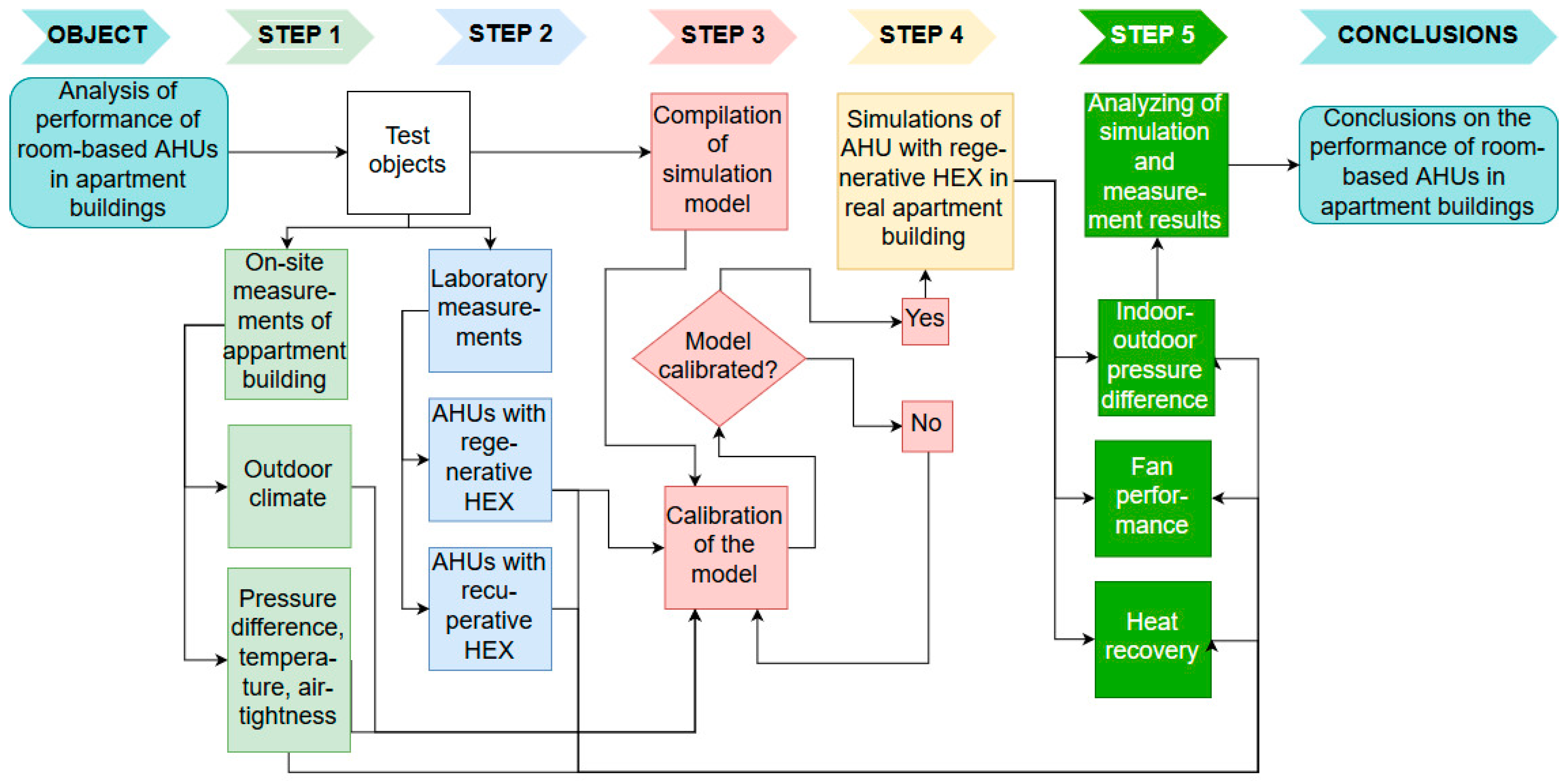
2. Methods
2.1. Measurements
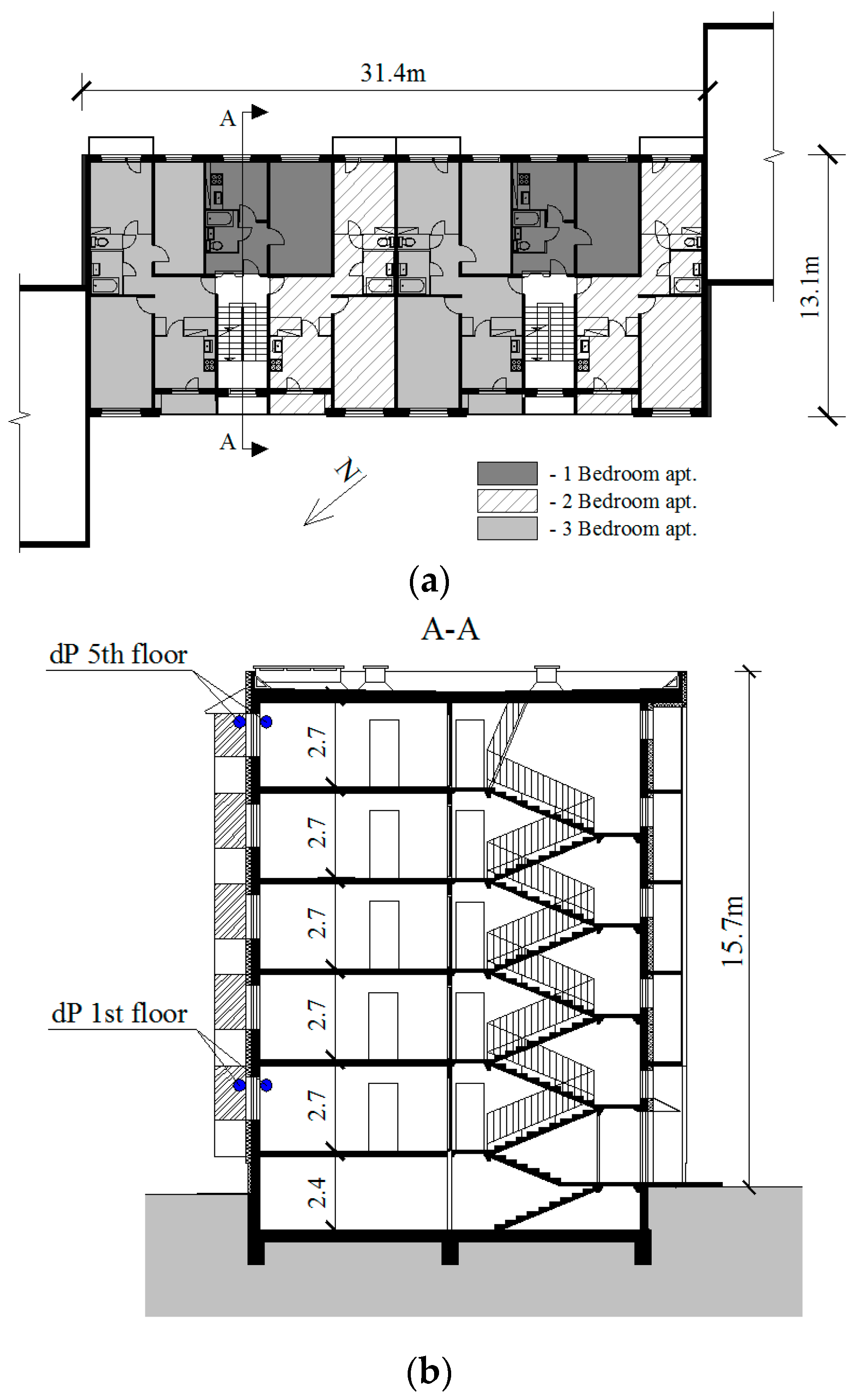
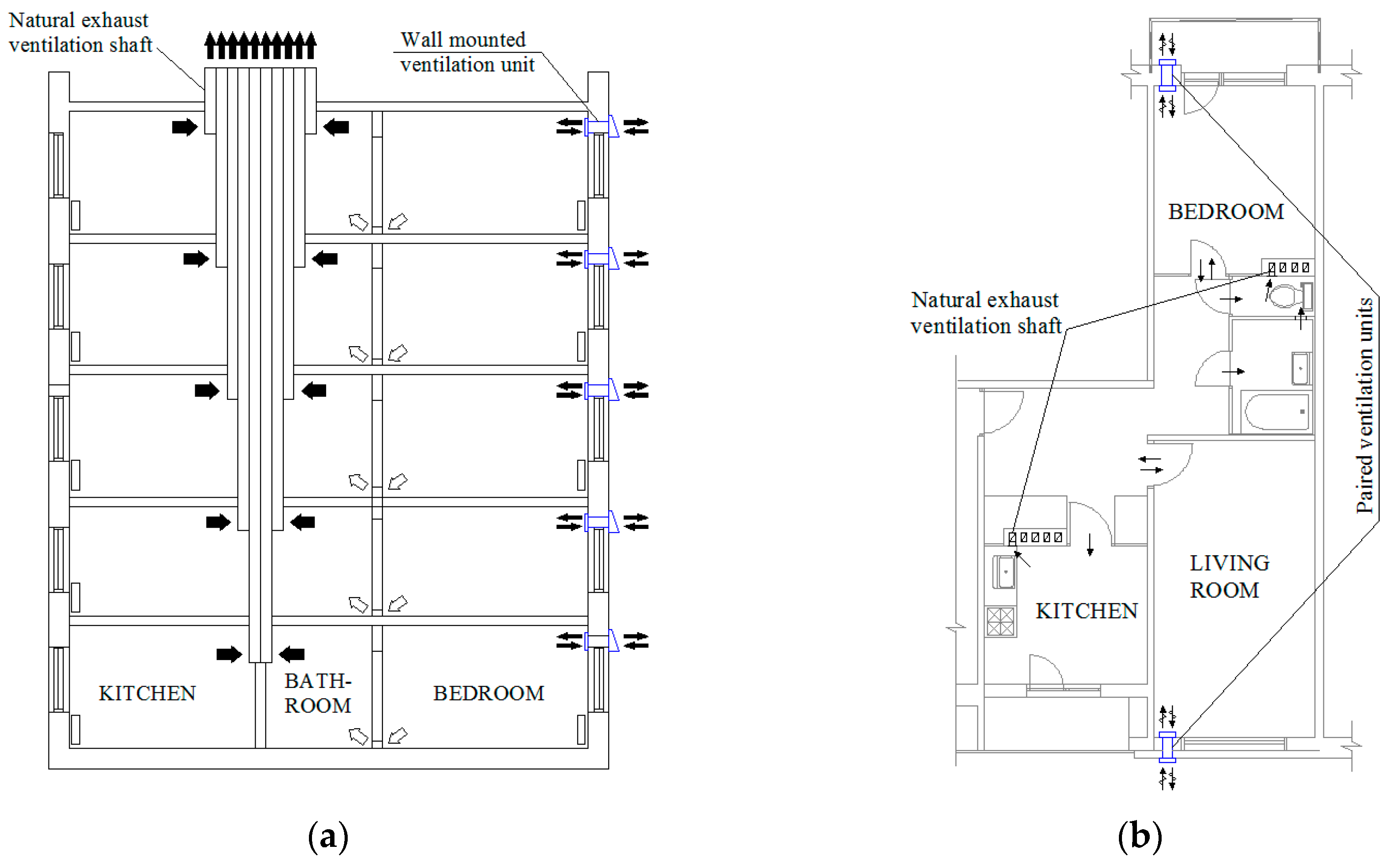
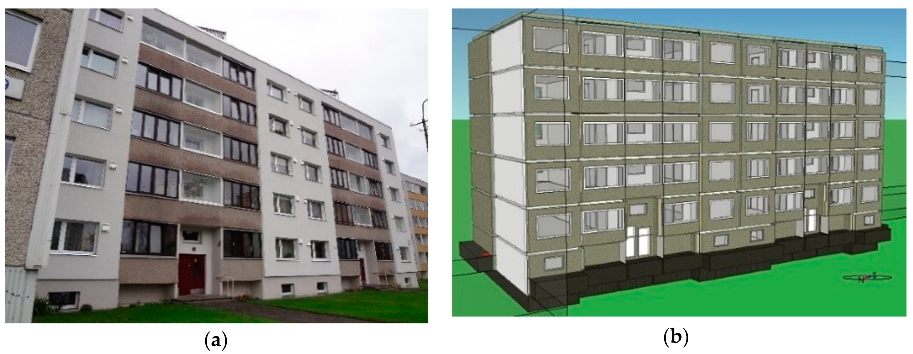
2.1.1. The Studied Building
2.1.2. Field Measurements
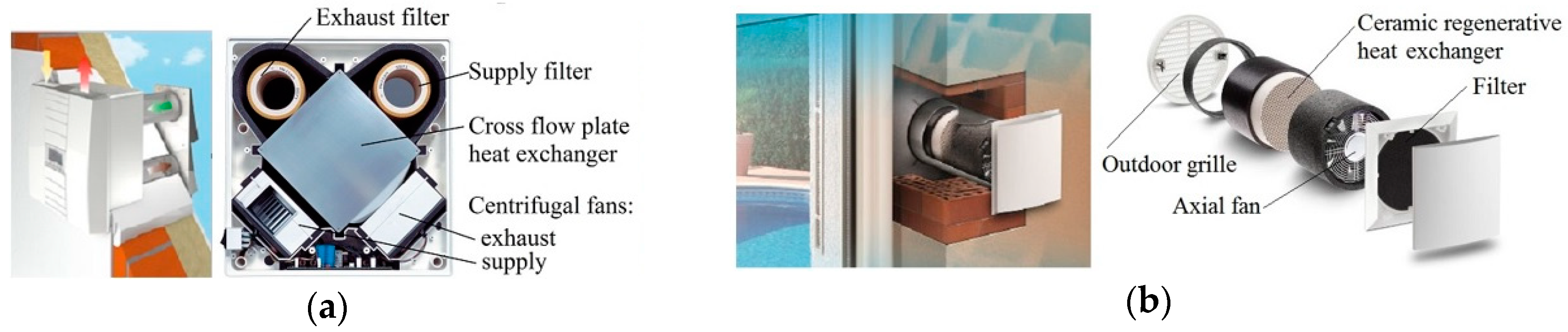
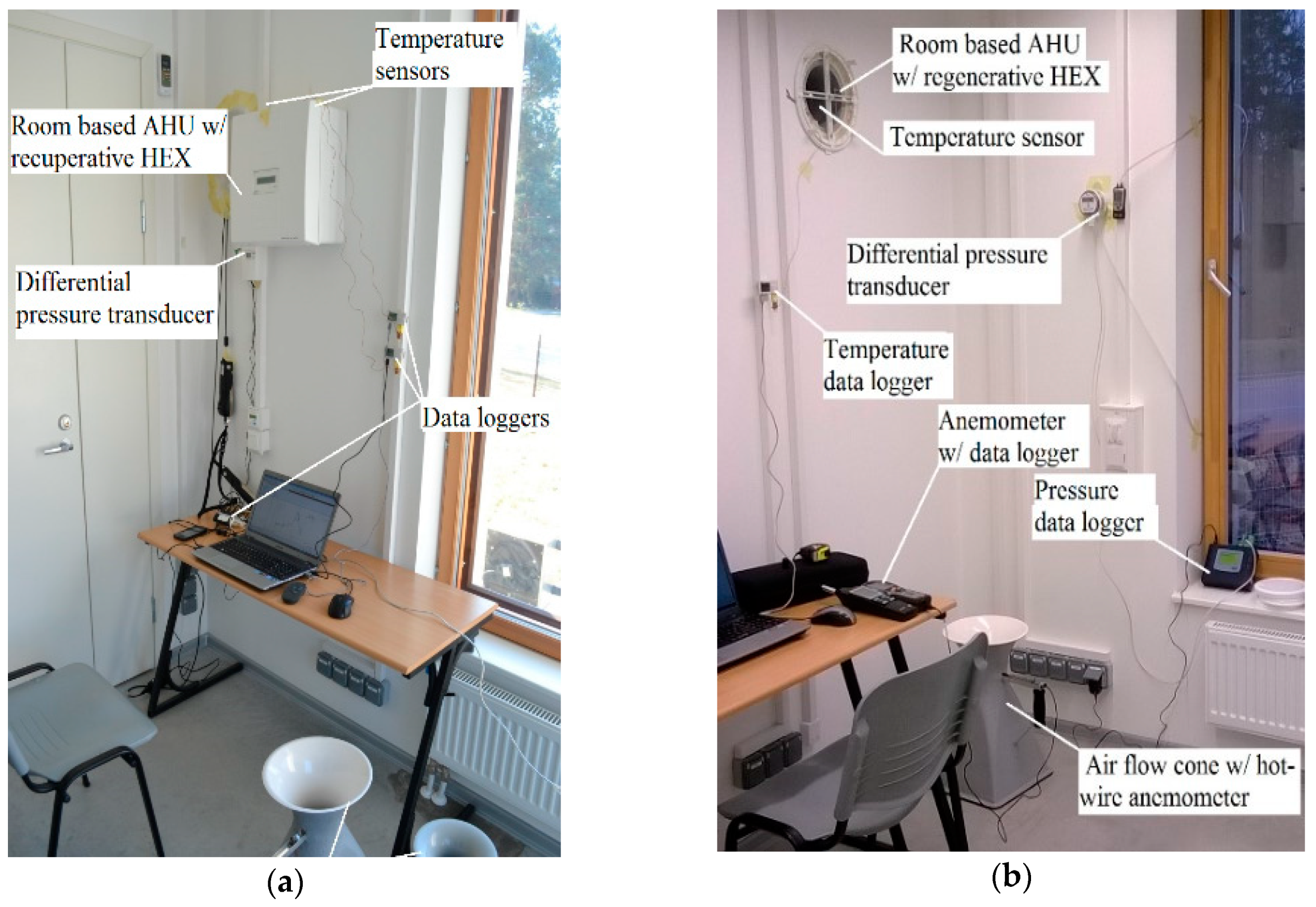
2.1.3. Laboratory Measurements
2.1.4. Temperature Efficiency of Room-Based Units
2.2. Computational Model
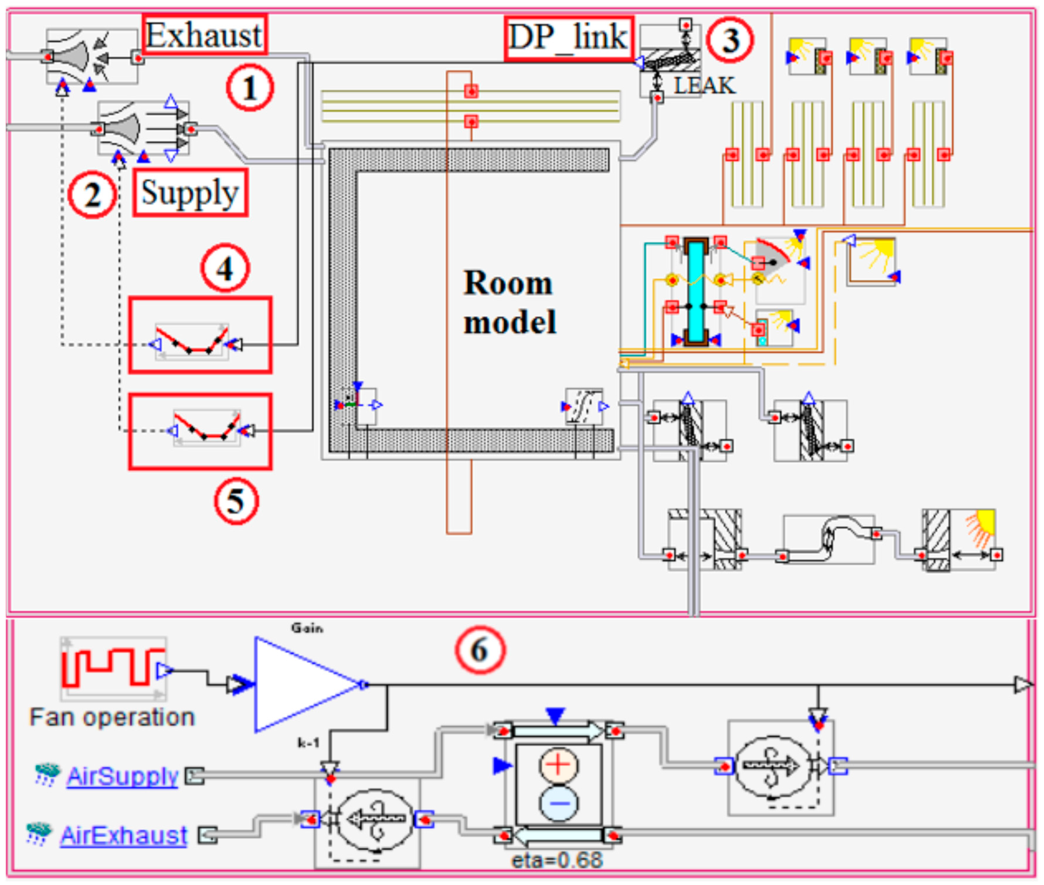
2.2.1. Description of Simulation Model
2.2.2. Air Pressure Calculations
3. Results
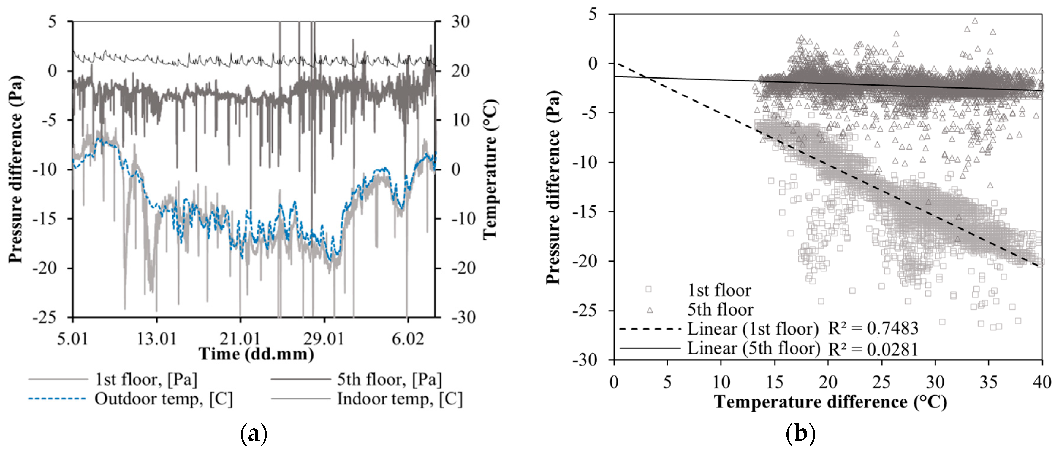
3.1. Field Measurements
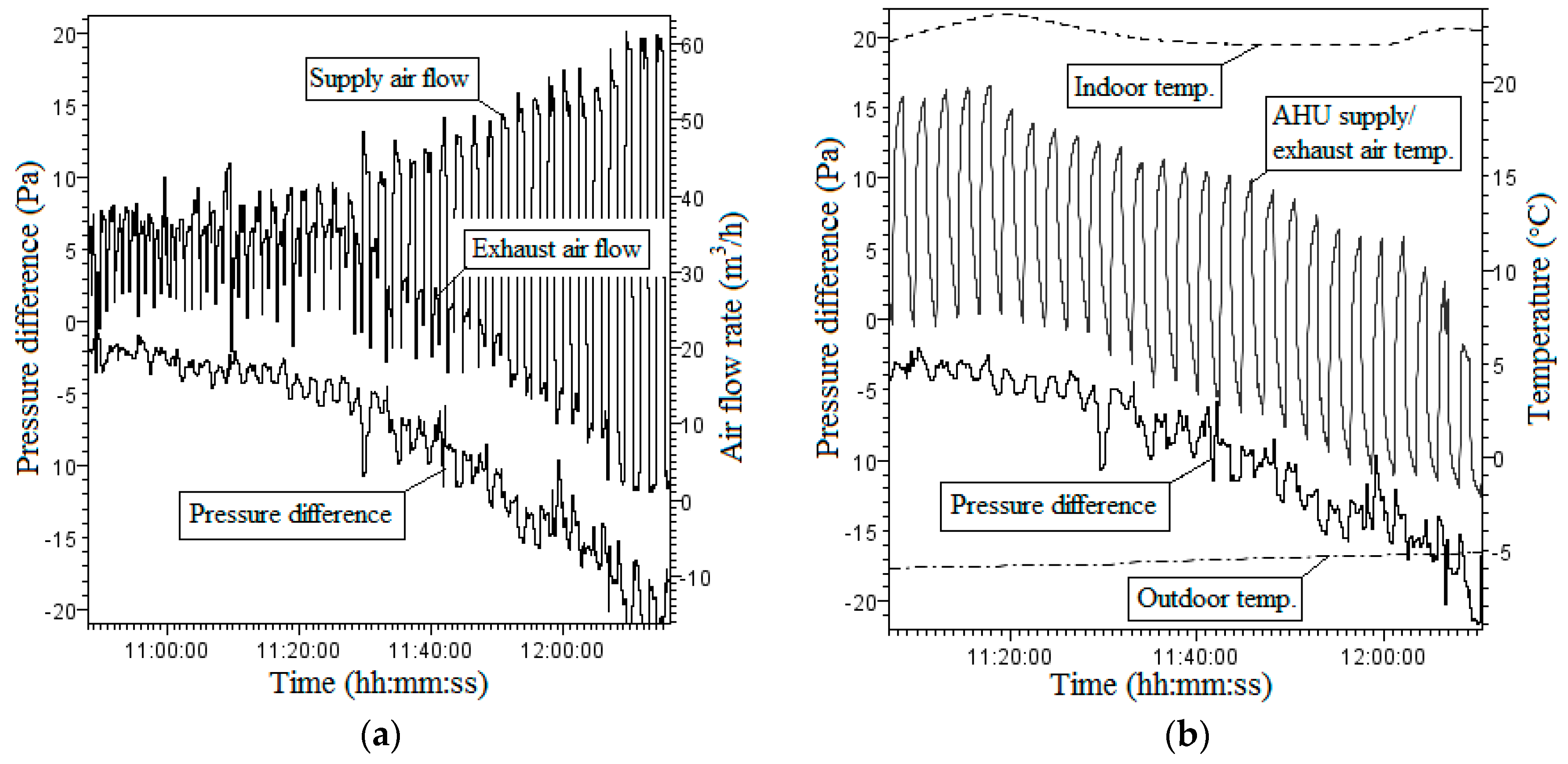
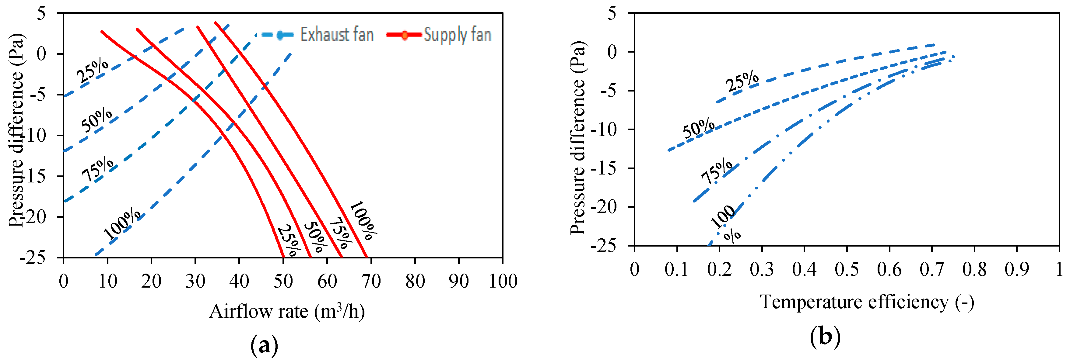
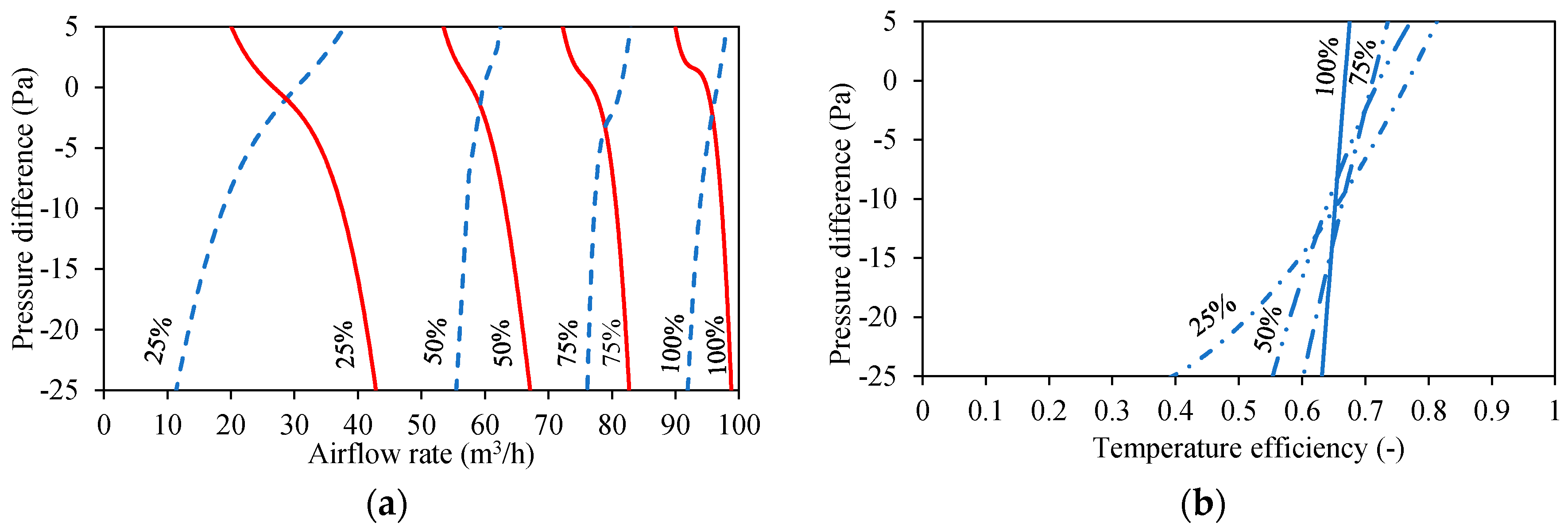
3.2. The Laboratory Measurements
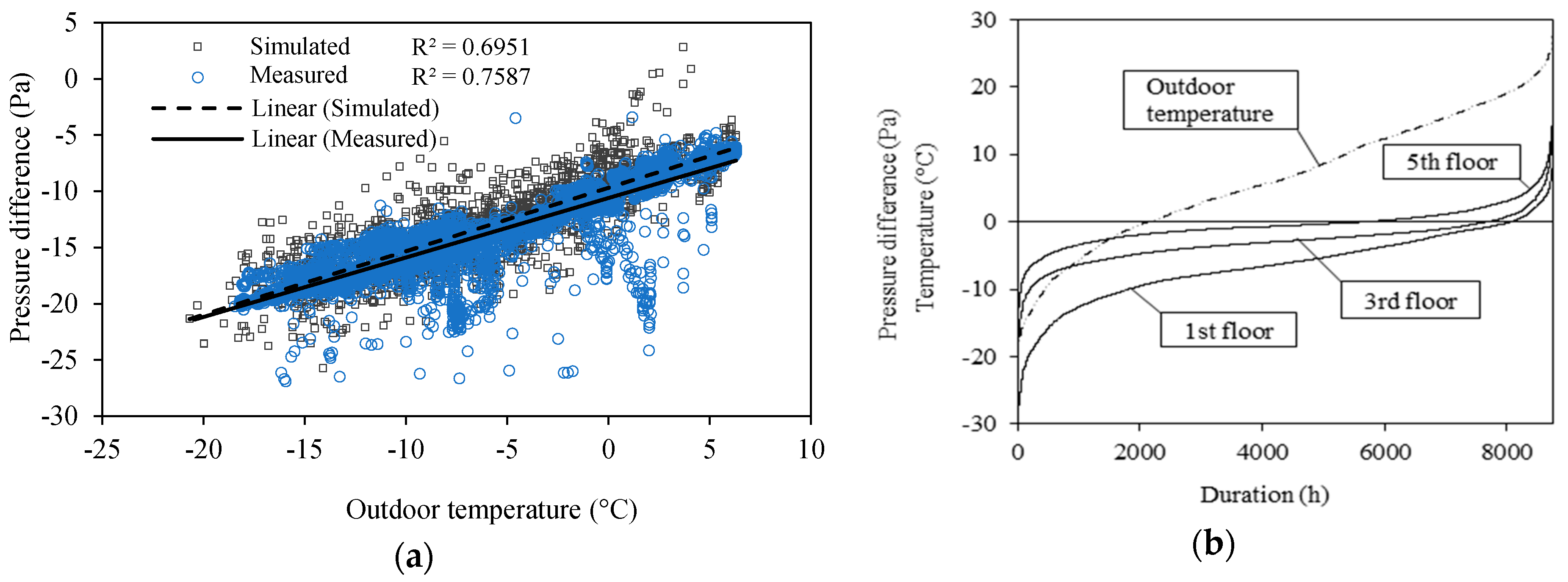
3.3. Simulation Results
4. Discussion
- Apartment based supply and exhaust ventilation system with heat recovery, with unit located in apartment, in corridor or staircase.
- Centralized supply and exhaust ventilation system with heat recovery, with unit located on roof, pipes located in external wall or in apartment.
- Centralized exhaust ventilation system with fresh air radiators and heat pump heat recovery.
5. Conclusions
Author Contributions
Funding
Acknowledgments
Conflicts of Interest
References
- Kuusk, K.; Kalamees, T.; Maivel, M. Cost effectiveness of energy performance improvements in Estonian brick apartment buildings. Energy Build. 2014, 77, 313–322. [Google Scholar] [CrossRef]
- Directive (EU) 2018/844 of the European Parliament and of the Council of 30 May 2018 Amending Directive 2010/31/EU on the Energy Performance of Buildings and Directive 2012/27/EU on Energy Efficiency. Available online: https://eur-lex.europa.eu/legal-content/EN/TXT/?uri=OJ:L:2018:156:TOC (accessed on 30 April 2019).
- Mikola, A.; Kõiv, T.-A.; Tennokese, K. Improving the indoor climate and energy saving in renovated apartment buildings in Estonia. In Proceedings of the 12th REHVA World Congress CLIMA 2016, Aalborg, Denmark, 22–25 May 2016. [Google Scholar]
- Mikola, A.; Kõiv, T.-A.; Kalamees, T. Quality of ventilation systems in residential buildings: Status and perspectives in Estonia. In Proceedings of the International Workshop Securing the Quality of Ventilation Systems in Residential Buildings: Status and Perspectives, Brussels, Belgium, 18–19 March 2013. [Google Scholar]
- Kalamees, T.; Kuusk, K.; Arumägi, E.; Ilomets, S.; Maivel, M. The analysis of measured energy consumption in apartment buildings in Estonia. In Proceedings of the IEA Annex 55 (RAP-RETRO), Working Meeting, Vienna, Austria, 23–25 April 2012. [Google Scholar]
- Kurnitski, J.; Kuusk, K.; Tark, T.; Uutar, A.; Kalamees, T.; Pikas, E. Energy and investment intensity of integrated renovation and 2030 cost optimal savings. Energy Build. 2014, 75, 51–59. [Google Scholar] [CrossRef]
- Hamburg, A.; Kalamees, T. The Influence of Energy Renovation on the Change of Indoor Temperature and Energy Use. Energies 2018, 11, 3179. [Google Scholar] [CrossRef]
- Kuusk, K.; Kalamees, T. Estonian Grant Scheme for Renovating Apartment Buildings. Energy Procedia 2016, 96, 628–637. [Google Scholar] [CrossRef] [Green Version]
- Paap, L.; Mikola, A.; Kõiv, T.-A.; Kalamees, T. Airtightness and ventilation of new Estonian apartments constructed 2001-2010. In Proceedings of the Joint Conference 33rd AIVC Conference and 2nd TightVent Conference Optimising Ventilative Cooling and Airtightness for [Nearly] Zero-Energy Buildings, IAQ and Comfort, Copenhagen, Denmark, 10–11 October 2012. [Google Scholar]
- Armstrong, P.; Dirks, J.; Klevgard, L.; Matrosov, Y.; Olkinuora, J. Infiltration and Ventilation in Russian Multi-Family Buildings. In Proceedings of the ACEEE Summer Study on Energy Efficiency in Buildings, Residential Buildings: Technologies, Design, and Performance Analysis, Pacific Grove, CA, USA, 25–31 August 1996. [Google Scholar]
- Wargocki, P.; Sundell, J.; Bischof, W.; Brundrett, G.; Fanger, P.; Gyntelberg, F.; Hanssen, S.; Harrison, P.; Pickering, A.; Seppanen, O.; et al. Ventilation and health in non-industrial indoor environments: Report from a European Multidisciplinary Scientific Consensus Meeting (EUROVEN). Indoor Air 2002, 12, 113–128. [Google Scholar] [CrossRef] [PubMed]
- Iversen, M.; Bach, E.; Lundqvist, G. Health and comfort changes among tenants after retrofitting of their housing. Environ. Int. 1986, 12, 161–166. [Google Scholar] [CrossRef]
- Menzies, R.; Tamblyn, R.; Farant, J.; Hanley, J.; Nunes, F.; Tamblyn, R. The Effect of Varying Levels of Outdoor-Air Supply on the Symptoms of Sick Building Syndrome. N. Engl. J. Med. 1993, 328, 821–827. [Google Scholar] [CrossRef] [PubMed]
- Seppanen, O.; Fisk, W.; Mendell, M. Association of Ventilation Rates and CO2 Concentrations with Health andOther Responses in Commercial and Institutional Buildings. Indoor Air 1999, 9, 226–252. [Google Scholar] [CrossRef]
- Ucci, M.; Ridley, I.; Pretlove, S.; Davies, M.; Mumovic, D.; Oreszczyn, T.; McCarthy, M.; Singh, J. Ventilation rates and moisture-related allergens in UK dwellings. In Proceedings of the 2nd WHO International Housing and Health Symposium, Vilnius, Lithuania, 29 September–1 October 2004. [Google Scholar]
- Ruotsalainen, R.; Jaakkola1, J.; Ronnberg, R.; Majanen, A.; Seppanen, O. Symptoms and Perceived Indoor Air Quality among Occupants of Houses and Apartments with Different Ventilation Systems. Indoor Air 1991, 1, 428–438. [Google Scholar] [CrossRef]
- Noris, F.; Adamkiewicz, G.; Delp, W.; Hotchi, T.; Russell, M.; Singer, B.; Spears, M.; Vermeer, K.; Fisk, W. Indoor environmental quality benefits of apartment energy retrofits. Build. Environ. 2013, 68, 170–178. [Google Scholar] [CrossRef] [Green Version]
- Hamburg, A.; Kalamees, T. Improving the indoor climate and energy saving in renovated apartment buildings in Estonia. In Proceedings of the 9th International Cold Climate HVAC 2018, Kiruna, Sweden, 12–15 March 2018. [Google Scholar]
- Jokisalo, J.; Kurnitski, J.; Korpi, M.; Kalamees, T.; Vinha, J. Building leakage, infiltration, and energy performance analyses for Finnish detached houses. Build. Environ. 2009, 44, 377–387. [Google Scholar] [CrossRef]
- Papakostas, K.; Kiosis, G. Heat recovery in an air-conditioning system with air-to-air HEX. Int. J. Sustain. Energy 2014, 34, 221–231. [Google Scholar] [CrossRef]
- El Fouih, Y.; Stabat, P.; Rivière, P.; Hoang, P.; Archambault, V. Adequacy of air-to-air heat recovery ventilation system applied in low energy buildings. Energy Build. 2012, 54, 29–39. [Google Scholar] [CrossRef]
- Merzkirch, A.; Maas, S.; Scholzen, F.; Waldmann, D. Field tests of centralized and decentralized ventilation units in residential buildings—Specific fan power, heat recovery efficiency, shortcuts and volume flow unbalances. Energy Build. 2016, 116, 376–383. [Google Scholar] [CrossRef]
- Kim, M.; Baldini, L. Energy analysis of a decentralized ventilation system compared with centralized ventilation systems in European climates: Based on review of analyses. Energy Build. 2016, 111, 424–433. [Google Scholar] [CrossRef]
- Santos, H.; Leal, V. Energy vs. ventilation rate in buildings: A comprehensive scenario-based assessment in the European context. Energy Build. 2012, 54, 111–121. [Google Scholar] [CrossRef]
- Smith, K.; Svendsen, S. Development of a plastic rotary HEX for room-based ventilation in existing apartments. Energy Build. 2015, 107, 1–10. [Google Scholar] [CrossRef]
- Manz, H.; Huber, H.; Schälin, A.; Weber, A.; Ferrazzini, M.; Studer, M. Performance of single room ventilation units with recuperative or regenerative heat recovery. Energy Build. 2000, 31, 37–47. [Google Scholar] [CrossRef]
- Liu, J.; Li, W.; Liu, J.; Wang, B. Efficiency of energy recovery ventilator with various weathers and its energy saving performance in a residential apartment. Energy Build. 2010, 42, 43–49. [Google Scholar] [CrossRef]
- Hosseini, S.M.; Carli, R.; Dotoli, M. Model Predictive Control for Real-Time Residential Energy Scheduling under Uncertainties. In Proceedings of the IEEE International Conference on Systems, Man, and Cybernetics (SMC), Miyazaki, Japan, 7–10 October 2018; pp. 1386–1391. [Google Scholar]
- Chen, J.; Augenbroe, G.; Song, X. Lighted-weighted model predictive control for hybrid ventilation operation based on clusters of neural network models. Autom. Constr. 2018, 89, 250–265. [Google Scholar] [CrossRef]
- Kalamees, T.; Kurnitski, J.; Jokisalo, J.; Eskola, L.; Jokiranta, K.; Vinha, J. Measured and simulated air pressure conditions in Finnish residential buildings. Build. Serv. Eng. Res. Technol. 2010, 31, 177–190. [Google Scholar] [CrossRef]
- Khoukhi, M.; Al-Maqbali, A. Stack Pressure and Airflow Movement in High and Medium Rise buildings. Energy Procedia 2011, 6, 422–431. [Google Scholar] [CrossRef] [Green Version]
- Khoukhi, M.; Yoshino, H.; Liu, J. The effect of the wind speed velocity on the stack pressure in medium-rise buildings in cold region of China. Build. Environ. 2007, 42, 1081–1088. [Google Scholar] [CrossRef]
- Acred, A.; Hunt, G. Multiple Flow Regimes in Stack Ventilation of Multi-Story Atrium Buildings. Int. J. Vent. 2013, 12, 31–40. [Google Scholar] [CrossRef]
- Tovar, T.; Garrido, C. Stack-Driven Ventilation in Two Interconnected Rooms Sharing a Single Opening and Connected to the Exterior by a Lower Vent. Int. J. Vent. 2010, 9, 211–226. [Google Scholar] [CrossRef]
- Kalamees, T.; Arumägi, E.; Tähiste, M. Air tightness of apartment buildings in Estonia. In Proceedings of the 4th International Symposium on Building and Ductwork Air Tightness (BUILDAIR)/30th AIVC Conference: Trends in High Performance Buildings and the Role of Ventilation, Berlin, Germany, 1–2 October 2009. [Google Scholar]
- Gładyszewska-Fiedoruk, K.; Gajewski, A. Effect of wind on stack ventilation performance. Energy Build. 2012, 51, 242–247. [Google Scholar] [CrossRef]
- Etheridge, D. Wind Turbulence and Multiple Solutions for Opposing Wind and Buoyancy. Int. J. Vent. 2009, 7, 309–320. [Google Scholar] [CrossRef]
- Kalamees, T.; Korpi, M.; Eskola, L.; Kurnitski, J.; Vinha, J. The distribution of the air leakage places and thermal bridges in Finnish detached houses and apartment buildings. In Proceedings of the 8th Symposium on Building Physics in the Nordic Countries: Dept. of Civil Engineering, Copenhagen, Denmark, 16–18 June 2008. [Google Scholar]
- Jo, J.; Lim, J.; Song, S.; Yeo, M.; Kim, K. Characteristics of pressure distribution and solution to the problems caused by stack effect in high-rise residential buildings. Build. Environ. 2007, 42, 263–277. [Google Scholar] [CrossRef]
- Mikola, A.; Kalamees, T.; Kõiv, T.-A. Performance of ventilation in Estonian apartment buildings. Energy Procedia 2017, 132, 963–968. [Google Scholar] [CrossRef]
- Kalamees, T.; Kurnitski, J. Estonian Test Reference Year for Energy Calculations. Proc. Est. Acad. Sci. Eng. 2006, 12, 40–58. [Google Scholar]
- Kuusk, K.; Kalamees, T.; Link, S.; Ilomets, S.; Mikola, A. Case-study analysis of concrete large-panel apartment building at pre- and post low-budget energy-renovation. J. Civ. Eng. Manag. 2016, 23, 67–75. [Google Scholar] [CrossRef]
- ASHRAE. Airflow around buildings. In Book 1993 ASHRAE Handbook-Fundamentals; American Society of Heating, Refrigerating and Air Conditioning Engineers: Atlanta, GA, USA, 1993. [Google Scholar]
- Smith, K.; Svendsen, S. The effect of a rotary HEX in room-based ventilation on indoor humidity in existing apartments in temperate climates. Energy Build. 2016, 116, 349–361. [Google Scholar] [CrossRef]
- Peng, X.; Yang, L.; Gavanski, E.; Gurley, K.; Prevatt, D. A comparison of methods to estimate peak wind loads on buildings. J. Wind Eng. Ind. Aerodyn. 2014, 126, 11–23. [Google Scholar] [CrossRef]
- Montazeri, H.; Blocken, B. CFD simulation of wind-induced pressure coefficients on buildings with and without balconies: Validation and sensitivity analysis. Build. Environ. 2013, 60, 137–149. [Google Scholar] [CrossRef]
- Grosso, M. Wind pressure distribution around buildings: A parametrical model. Energy Build. 1992, 18, 101–131. [Google Scholar] [CrossRef]
- Sherman, M.H.; Grimsrud, D. Infiltration-pressurization correlation: Simplified physical modeling. ASHRAE Trans. 1980, 86, 778–807. [Google Scholar]
- Modera, M.P.; Sherman, M.H.; Grimsrud, D.T. A Predictive Air Infiltration Model-Long-Term Field Test Validation. In Proceedings of the Semi-annual meeting of the American Society of Heating, Refrigerating, and Air Conditioning Engineers, Houston, TX, USA, 24 January 1982; Available online: https://www.osti.gov/biblio/6285265 (accessed on 4 March 2019).
- Kiviste, M.; Vinha, J. Air pressure difference measurements in Finnish municipal service buildings. Energy Procedia 2017, 132, 879–884. [Google Scholar] [CrossRef]
- Leivo, V.; Kiviste, M.; Aaltonen, A.; Turunen, M.; Haverinen-Shaughnessy, U. Air Pressure Difference between Indoor and Outdoor or Staircase in Multi-family Buildings with Exhaust Ventilation System in Finland. Energy Procedia 2015, 78, 1218–1223. [Google Scholar] [CrossRef] [Green Version]


| Part of the Thermal Envelope | Thermal Transmittance, W/(m2·K) | |
|---|---|---|
| Before | After | |
| External walls | 1.05 | 0.22 |
| Roof | 0.45 | 0.15 |
| Doors | 2.0 | 1.2 |
| Windows | 2.9 | 1.4 |
| Facade | Orientation | Wind Angle (°) | |||||||
|---|---|---|---|---|---|---|---|---|---|
| 0 | 45 | 90 | 135 | 180 | 225 | 270 | 315 | ||
| Exterior wall | NE | 0.4 | 0.2 | −0.6 | −0.5 | −0.3 | −0.5 | −0.6 | 0.2 |
| Exterior wall | SE | 0.25 | 0.06 | −0.35 | −0.6 | −0.5 | −0.6 | −0.35 | 0.06 |
| Exterior wall | SW | 0.4 | 0.2 | −0.6 | −0.5 | −0.3 | −0.5 | −0.6 | 0.2 |
| Exterior wall | NW | 0.4 | 0.2 | −0.6 | −0.5 | −0.3 | −0.5 | −0.6 | 0.2 |
| Roof | −0.8 | −0.8 | −0.8 | −0.8 | −0.8 | −0.8 | −0.8 | −0.8 | |
© 2019 by the authors. Licensee MDPI, Basel, Switzerland. This article is an open access article distributed under the terms and conditions of the Creative Commons Attribution (CC BY) license (http://creativecommons.org/licenses/by/4.0/).
Share and Cite
Mikola, A.; Simson, R.; Kurnitski, J. The Impact of Air Pressure Conditions on the Performance of Single Room Ventilation Units in Multi-Story Buildings. Energies 2019, 12, 2633. https://doi.org/10.3390/en12132633
Mikola A, Simson R, Kurnitski J. The Impact of Air Pressure Conditions on the Performance of Single Room Ventilation Units in Multi-Story Buildings. Energies. 2019; 12(13):2633. https://doi.org/10.3390/en12132633
Chicago/Turabian StyleMikola, Alo, Raimo Simson, and Jarek Kurnitski. 2019. "The Impact of Air Pressure Conditions on the Performance of Single Room Ventilation Units in Multi-Story Buildings" Energies 12, no. 13: 2633. https://doi.org/10.3390/en12132633