Article

Implementation of a Microgrid Scheme Using a MVDC Connection between Gapado Island and Marado Island in South Korea

Department of Electrical Engineering, College of Engineering, Jeju National University, Jeju 63243, Korea
*
Author to whom correspondence should be addressed.
Energies 2019, 12(1), 187; https://doi.org/10.3390/en12010187
Submission received: 31 October 2018 / Revised: 3 January 2019 / Accepted: 3 January 2019 / Published: 8 January 2019
(This article belongs to the Special Issue Power Electronics for Energy Storage)

Abstract

:
In this paper, we propose a microgrid (MG) implementation method through Medium-Voltage Direct Current (MVDC) connection between Gapado Island and Marado Island in Korea. MVDC is a facility that can be efficiently applied between small power generation complexes. The structure of power generation facilities is mainly supplied by diesel generators, while solar and wind power generators supply additional power. An Energy Storage System (ESS) is also used to reduce the output fluctuations of wind and solar power generation. Since power systems in such areas are low-voltage and low-power distribution systems, problems can arise in terms of power management due to power generators with variable output characteristics such as solar power and wind power generators. In addition, when a major power source such as a diesel generator is dropped, the power system collapses. However, these problems can be solved by interchanging the power between the micro-grids through the connection of MVDCs. With the MVDC connected, we verify the impact of the power system on Marado Island and Gapado Island due to the input and opening of solar, wind and diesel generators. The proposed configuration uses the PSCAD/EMTDC simulation program.

1. Introduction

Recently, microgrids using renewable energy sources have been actively constructed in island areas where there are no commercial power connections to the rest of the world. In such areas, diesel generators are used as the main power source, but there are many places where renewable energy sources such as solar power and wind power are connected and operated. However, a renewable energy source with high output fluctuation characteristics is disadvantageous in terms of power management and efficiency. Because the power consumed in the islands is consumed in the residence, except for some special areas, consumption patterns are almost constant.
However, renewable energy sources such as solar power or wind power cannot be generated according to the load type of power consumption but depend on environmental factors such as solar radiation and wind speed. Therefore, countermeasures are necessary for renewable energy sources to serve as stable power sources. Among the facilities for this purpose, the energy storage device is now the most popular.
Among the ESS, batteries are being used most often to mitigate the fluctuation of renewable energy sources with the tendency that prices have recently been getting lower. In operating such a power system, it is necessary to find a way to reduce the existing diesel power that is being operated on each island and to use the output of renewable energy source as much as possible. In particular, it is difficult to stably operate the system by combining diesel and renewable energy sources in Marado Island and Gapado Island with maximum power consumption of (240 and 300) kW, respectively. In order to solve this problem, this paper proposes a method to stabilize the power system through the complementary operation, in the case of power output problem, in each island, by linking it with the MVDC model of power system of Gapado Island and Marado Island located in the south area of South Korea. New technology has not been applied to MVDC system which still has the same structure and operation characteristics as existing HVDC systems and only has a difference in voltage level [1]. The MVDC system is the distribution voltage level (~several kV) and the HVDC system is the transmission voltage level (hundreds of kV). Recently, MVDC system has been applied to large ships and distribution power system [1,2]. We verify this through the results of the PSCAD/EMTDC simulation program.

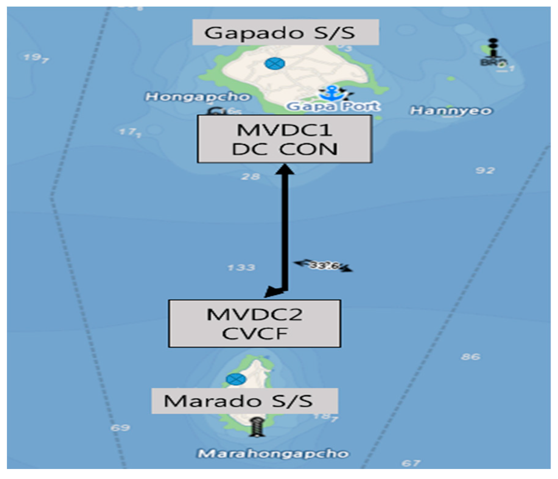
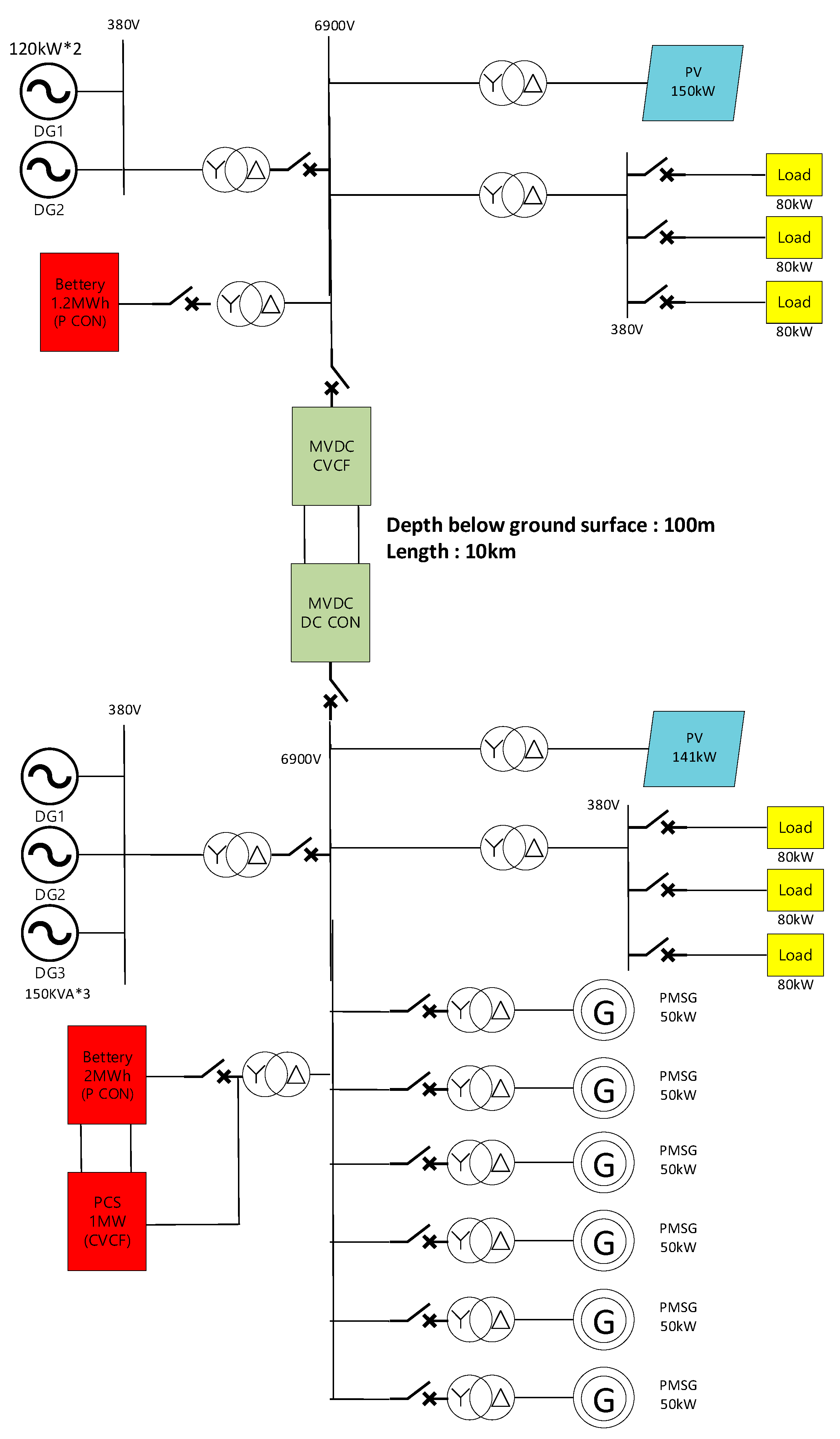
2. Proposed System for Gapado Island and Marado Island

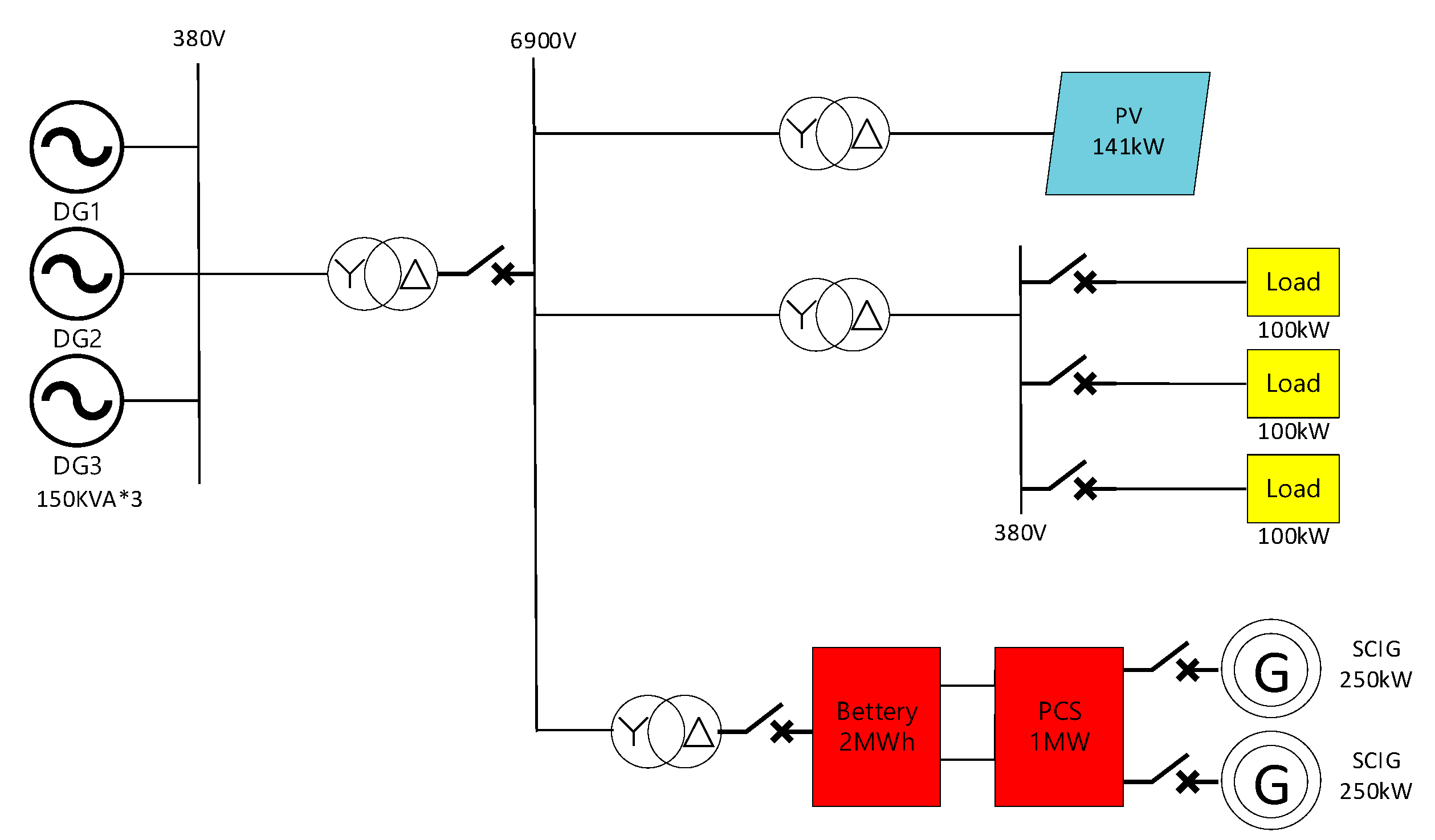
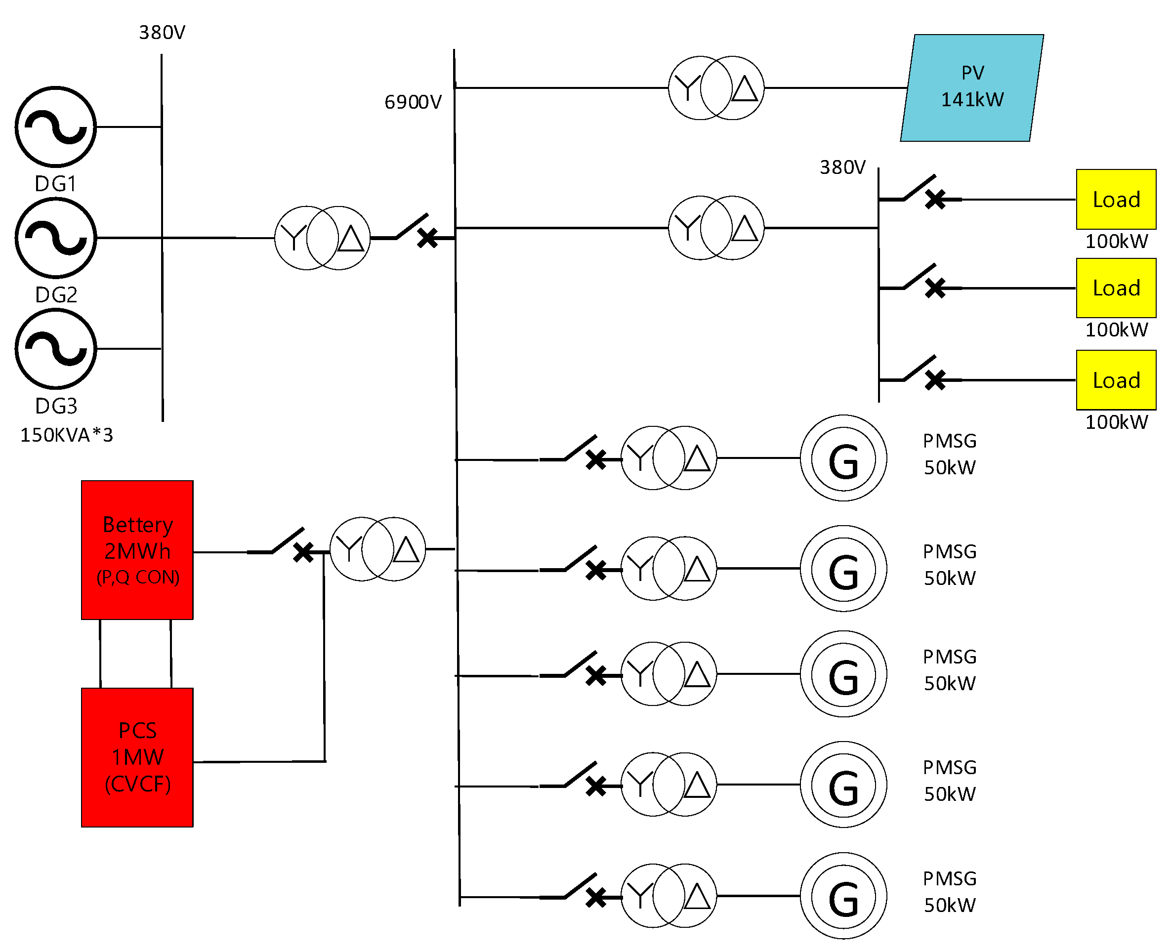
2.1. Gapado Island Power Grid

Gapado Island is located 2.3 km south of Jejudo Island in South Korea. Figure 1 shows that the power system of a Gapado Island consists of a 1 MVA Power Conversion System (PCS) with a 2 MWh battery, and two of the three 150 KVA diesel generators operate at all times, with the remaining one in reserve. The system consists of two 250 kW induction wind turbines, transformer, and power consumer load for grid connection with renewable energy facilities, including 141 kW capacity photovoltaic power generation facilities. Here, the cage induction type wind turbine and solar output are stored in the battery, and supplied to the power load of the island. When the wind speed is low or when the wind turbine is stopped, due to the failure of the wind turbine, the remaining capacity of the battery is reduced due to the continuous discharge. In this case, the auxiliary diesel generator operates to store power in the battery. The average power consumption of Gapado Island is 119 kW, and the maximum power consumption is about 300 kW. The main power load consists of a small factory load and home electrical load [3].
The problem of the power system of Gapado Island is that the two grid-connected 250 kW squirrel cage induction generator (SCIG) type wind turbine generators are concentrated in one area, and at the same time, grid connection and the dropout of the two wind turbines, a serious problem to the stability of the island power system. SCIG has the advantage of low cost and simple structure, but it has the disadvantage that reactive power must be supplied from the grid during grid-connected operation. This causes the voltage stability of the power system to deteriorate, so that it is rarely employed in a standalone microgrid having a small system scale. In addition, as shown in Figure 1, the capacities of the two SCIG type wind turbine installed on the islands are larger than the average power load capacities of the islands, and excessive starting currents cause system voltage fluctuations, resulting in flicker [4]. In order to solve such a problem, a permanent magnet synchronous generator (PMSG) which generates less inrush current due to initial startup is employed.
In addition, the existing 2 MWh capacity battery system performs active power control so as to follow the variable power load in response to the regular output of the diesel generator installed on the island. At this time, under the condition that the diesel generator is not operated, 1 MW PCS can minimize the problems caused by existing system through Constant Voltage Constant Frequency (CVCF) operation. Figure 2, shows that we propose a new microgrid configuration in which several 50 kW PMSG type wind turbines are distributed in order to minimize the influence of wind power output [5,6].

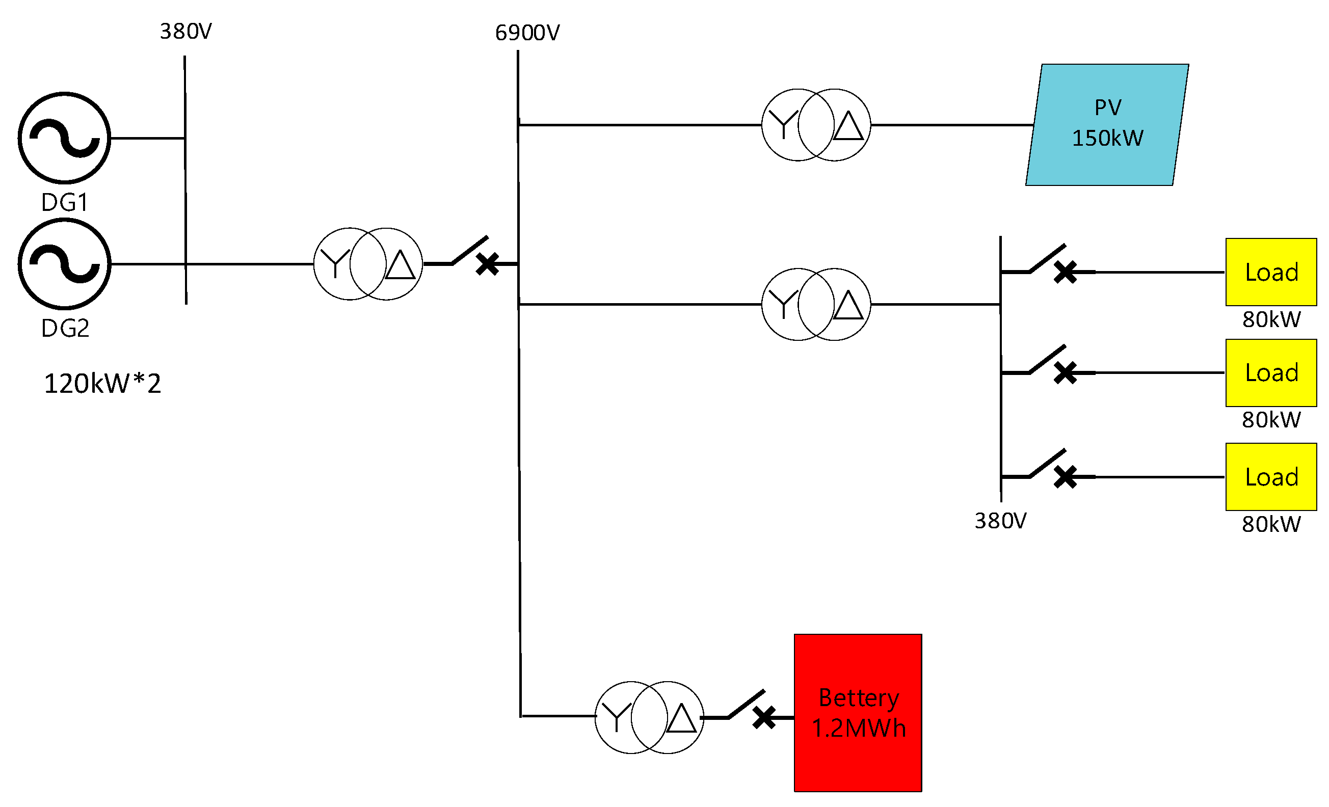
2.2. Marado Island Power Grid
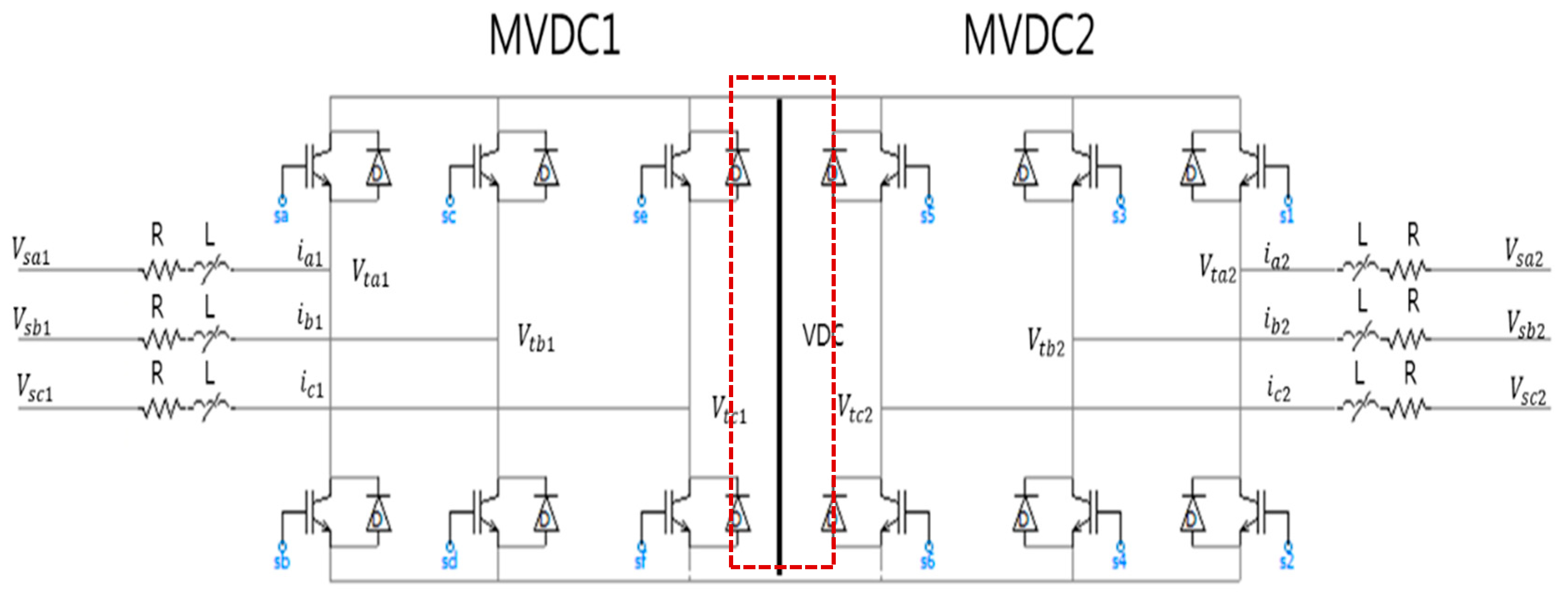
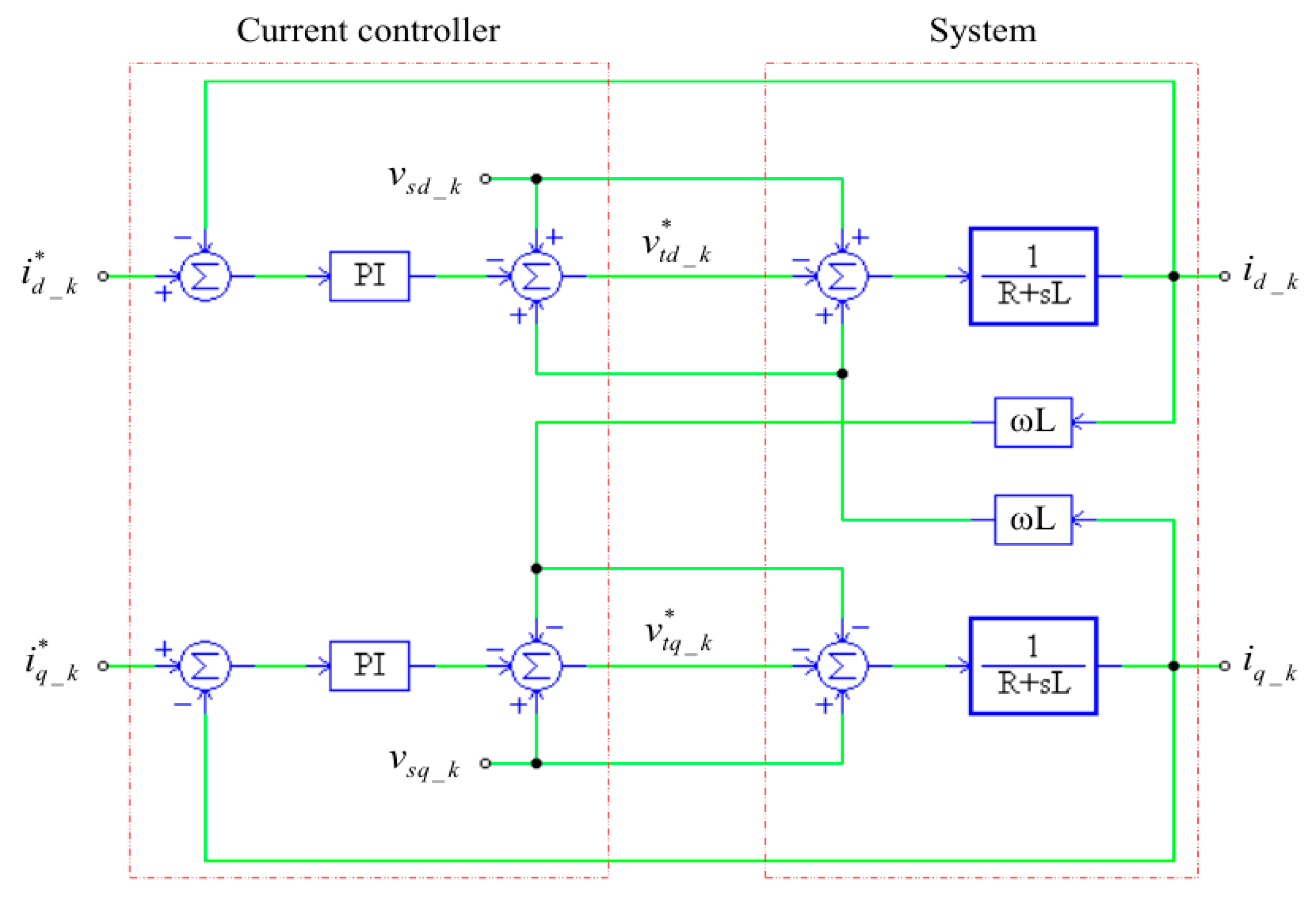
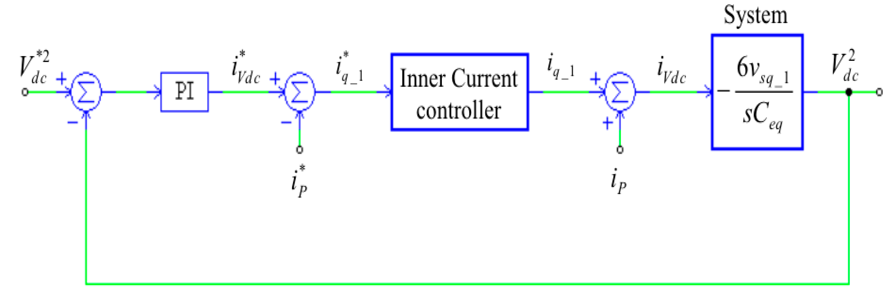
Marado Island is located about 5.5 km south of Gapado Island. Two power plants with 150 kW capacity are used as the main power source as shown in Figure 3. There are two battery systems with a capacity of 600 kWh, and two solar power plants with a capacity of 75 kW for solar power output fluctuation mitigation and emergency power reserve. The maximum load power consumption is about 240 kW [7]. There are three major power loads on this island. The first is the main moving method, the electric cart, so charging electric power here is the biggest power load. Here, the consumption time of the electric power load is from evening to morning. The second is the electric power load on the catering business for tourists, which is the power load mainly consumed during the daytime when tourists stay. The third is the power load that is constantly consumed throughout the day as the normal home electric load. As a result, the power load pattern of Marado Island is constantly consumed.
In this case, it is necessary to establish conditions that can supply electric power to the power system stably even in the case of dropout of diesel generator and emergency situation. Figure 3 shows a schematic of the existing Marado Island power grid. Currently, most diesel generators in the power system of this island have power supply, which can lead to a serious situation in which the entire power system is dropped when a fault occurs. Although a battery system is installed, it is currently not operating because of surplus power management and operational problems.
In order to solve these problems, a 1 MVA MVDC is connected to each island, so as to reduce power dependency on the output of the diesel generator of Marado Island. The power generated by utilizing the power generation is stored in the 1.2 MWh battery to stabilize the diesel output, and surplus power is transmitted through the MVDC to the Gapado Island power system. Also, when the power of the diesel generator installed on Marado Island is stopped and the power supply to the island is insufficient, the output of the emergency generator installed in Gapado Island is supplied to of Marado Island through the MVDC. At this time, we will propose a scheme that can be operated as an optimal microgrid by changing the structure and control algorithm of the power facilities at Gapado Island.

2.3. MVDC Control

The operation of the MVDC is proposed by defining the normal mode and the emergency mode.
  • Normal mode:
    Control voltage and frequency through active and reactive power output control of the grid.
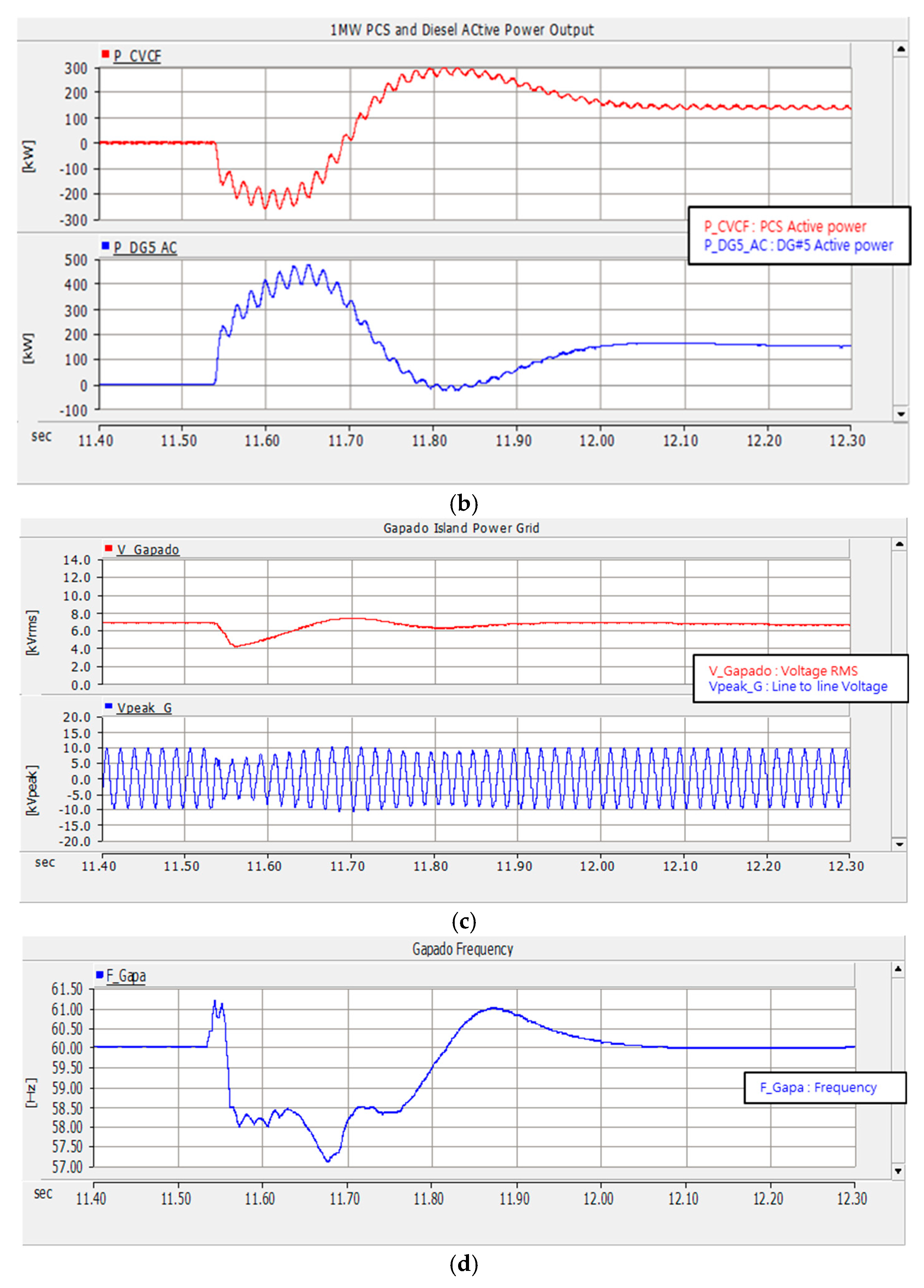
  • Emergency mode:
    If a diesel generator is dropped, it switches to CVCF mode and is forced to control the reference voltage (6.9 kV) and frequency (60 Hz). The MVDC is commanded to maintain maximum emergency mode until the diesel generator is able to operate normally.
Figure 4 shows A 1 MVA MVDC Link between Gapado Island and Marado Island. The Operation Algorithm of the MVDC is the same as the Control Method of the Battery System Installed in the Islands. The Diesel Generators Operated on Marado Island Have Active and Reactive Power Control According to the System Conditions in Normal Mode [8].
Figure 5 shows a circuit diagram of the 1 MVA MVDC system. Here the converter system exists on both sides with respect to the VDC. The Voltage sourced Converter also enables DC-Link voltage control, AC output voltage control, and independent active and reactive power control, respectively [9,10].
The AC voltage of the MVDC system can be indicated as follows:
V s j _ k = R i j _ k + L d i j _ k d t + V t j _ k
where j is expressed as a three-phase component of voltage and current, and is j = a, b, c. K is MVDC1 and MVDC2 in Figure 5, and k = 1, 2;   V s j _ k , V t j _ k and i j _ k are the 3-phase voltage and current of MVDC-k.; and R and L are the resistance and inductance of the system. Using Park’s transformation, the AC voltage can be used as a dq-frame, as shown in Equations (2) and (3):
V s d _ k = R i d _ k + L d i d _ k d t + V t d _ k ω L i q _ k
V s q _ k = R i q _ k + L d i q _ k d t + V t q _ k + ω L i d _ k
where V s d _ k , V s q _ k , V t d _ k , V t q _ k , i d _ k , i q _ k are the dq-axis component of the 3-phase voltage and the current of MVDC-k. From Equations (2) and (3) the dq-axis component of the terminal voltage can be used as follows:
V t d _ k = R i d _ k L d i d _ k d t + V s d _ k + ω L i q _ k
V t q _ k = R i q _ k L d i q _ k d t + V s q _ k ω L i d _ k
The terminal voltage is determined by the AC current and when PI control is used, the current control can be expressed as follows:
V t d _ k * = ( k p + k i s ) ( i d _ k * i d _ k ) + V s d _ k + ω L i q _ k
V t q _ k * = ( k p + k i s ) ( i q k * i q k ) + V s q k ω L i d _ k
where * is the reference value of the signal, and Equations (2) and (3) are expressed as a transfer function using the Laplace transformation:
V s d _ k = R i d _ k + s L i d _ k + V t d _ k * ω L i q _ k
> i d _ k = 1 R + s L ( V s d _ k V t d _ k * + ω L i q _ k )
V s q _ k = R i q _ k + s L i q _ k + V t q _ k * ω L i d _ k
> i q _ k = 1 R + s L ( V s q _ k V t q _ k * + ω L i d _ k )
Figure 6 shows the current control. PI control follows current reference values, and the voltage feed-forward conditions for current have been added to improve the control response [11,12,13].
Assuming that DC-Link voltage control ignores the internal loss of MVDC systems, the power balance expression is:
P d c = ( P 1 + P 2 )
where, Pdc is the power of the MVDC system on the DC side and is calculated as follows: [14,15]
P d c = V d c I d c = C e q 2 d V d c 2 d t
where, C e q is like a Capacitance between MVDC 1 and 2. P 1   and   P 2 are the active power of MVDC 1, and 2, can be calculated as follows:
P 1 = 3 2 ( V s d _ 1 i d _ 1 + V s q _ 1 i q _ 1 )
P 2 = 3 2 ( V s d _ 2 i d _ 2 + V s q _ 2 i q _ 2 )
Equation (10) may be replaced by Equations (12) and (13), and calculated as follows:
C e q 2 d V d c 2 d t = [ 3 2 ( V s d _ 1 i d _ 1 + V s q _ 1 i q _ 1 ) + 3 2 ( V s d _ 2 i d _ 2 + V s q _ 2 i q _ 2 ) ]
with vector control, the d-axis voltage component becomes zero and the amplitudes of the AC voltage on both sides of the MVDC are equal V s q _ 1 = V s q _ 2 . Equation (14) can therefore be rewritten as follows:
C e q 2 d V d c 2 d t = 3 2 V s q _ 1 ( i q _ 1 + i q _ 2 )
The Q-axis reference current i q _ 1 * and i q _ 2 * are defined as follows:
i q _ 1 * = i p * + i v d c *
i q _ 2 * = i p * + i v d c *
where, i p * is the current corresponding to the active power exchange between AC systems 1 and 2, and i v d c * is the small effective current for DC-Link voltage regulation. The solutions to Equations (16) and (17) are as follows:
i q _ 1 = i p + i v d c
i q _ 2 = i p + i v d c
Equations (18) and (19) are replaced and rearranged in Equation (15), to give:
d V d c 2 d t = 6 v s q _ 1 C e q i v d c
DC-Link voltage control can be derived from Equation (20):
i v d c * = ( K p + K i s ) ( V d c * 2 V d c 2 )
When considering V d c 2 as a variable of state, Equation (20) can be rewritten in the Laplace domain as Equation (22):
V d c 2 = 6 v s q _ 1 s C e q i v d c
Equation (22) relates to the DC-Link voltage and current components. MVDC 1 controls DC-Link voltage, and Figure 7 shows the control diagram of DC-Link voltage:
The active and reactive power sources of the MVDC system can be expressed as Equations (23) and (24):
P k = 3 2 ( V s q _ k i q _ k ) 3 2 ( V s q _ k i p )
Q k = 3 2 ( V s q _ k i d _ k )
where, P k and Q k are the active and reactive power sources of MVDC-k. Close loop control is applied to the power controller to monitor the output power of the converter system. Therefore, from Equations (23) and (24), the dq axis current control equation for controlling the active power and reactive power of the PCS using the PI controller is expressed by Equations (25) and (26):
i p * = ( K p + K i s ) ( P k * P k )
i d _ k * = ( K p + K i s ) ( Q k * Q k )
AC voltage control supplies grid voltage and is executed at MVDC-k control. From Figure 6, the voltage drop of the reactance RL is expressed by Equation (27):
Δ v k = v s _ k v t _ k = R P k + X Q k v s _ k + j X P k R Q k v s _ k
In Equation (27) the imaginary part is very small compared to the real part, and most power systems are X R . Voltage drop is rearranged to Equation (28):
Q k v s Δ v k X
The AC voltage is proportional to the reactive power, and voltage control is expressed by Equation (29):
Q k * = ( K p + K i s ) ( v r m s _ k * v r m s _ k )
The output signal of the voltage control is the reference value of the reactive power. According to the reference value of the voltage, MVDC-k exchanges the grid with the reactive power. Therefore, the proposed Marado Island and Gapado Island schematic is constructed as shown in Figure 8.

3. Simulation Results

The existing power system of Gapado and Marado Islands and the proposed power grid of each islands were modeled using the PSCAD/EMTDC simulation program. Simulation results show the operation characteristics of the transient state compared with those of the existing system and the proposed system.

3.1. Simulation of the Existing Power System in Marado Island and Gapado Island

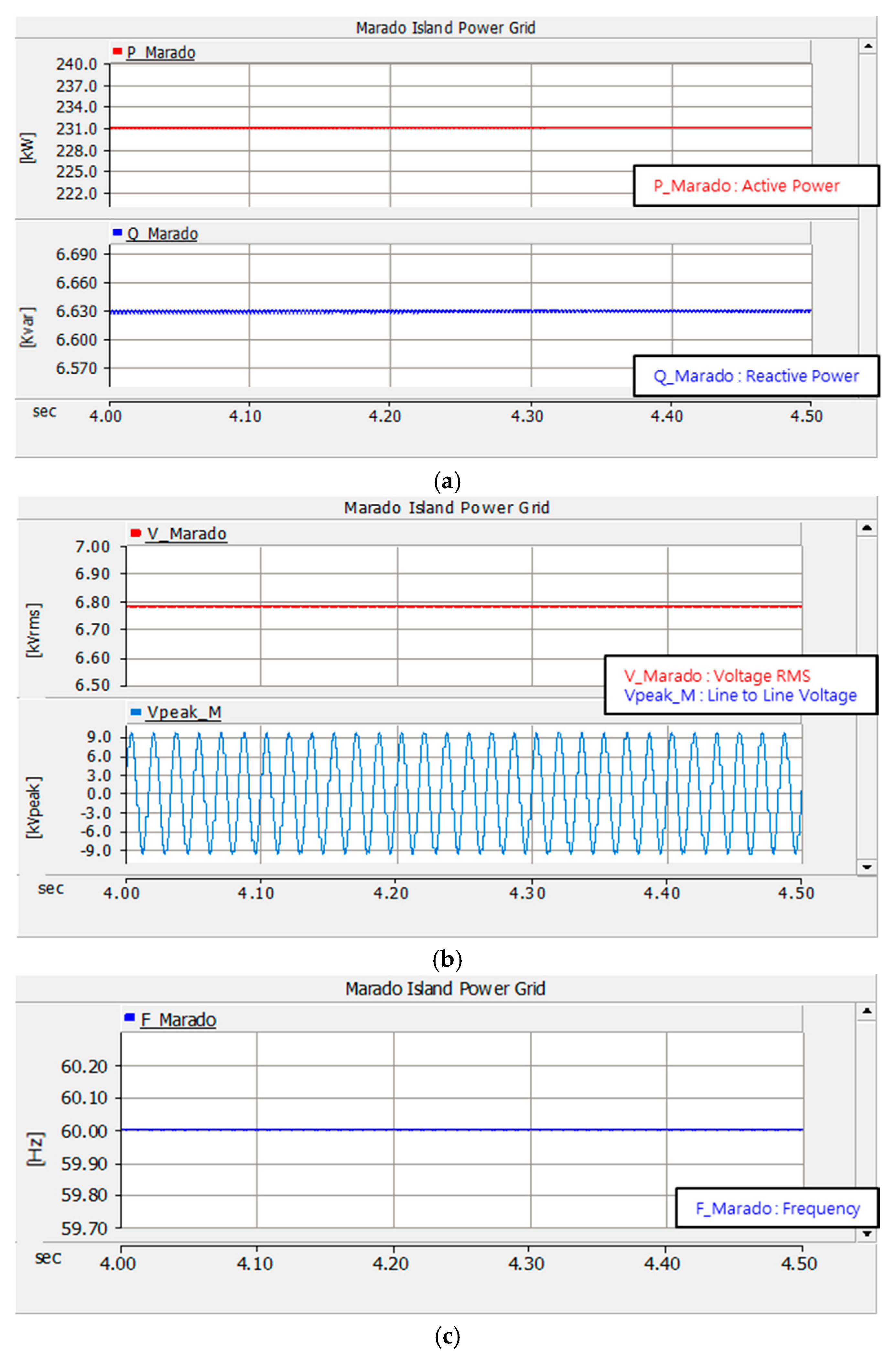
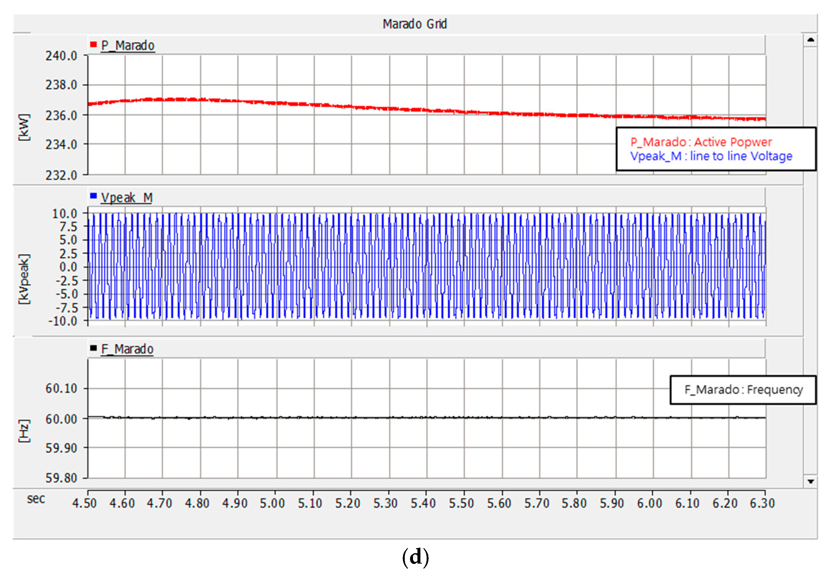
3.1.1. Marado Island Power Grid

The island power system consists of two 120 kW diesel generators and one 1.2 MWh battery system. Because the maximum power load is 240 kW, the power load model has three 80 kW capacity. The computer analysis analyzes the voltage, current, frequency and power changes of Marado Island power system due to steady state operation and the simultaneous drop of two diesel generators. In addition, since the PV power generation is not actually operating, it is excluded from the parameter of the dropout condition.
• Steady State
Figure 9a–c show the Marado Island grid waveform at steady state. Table 1 shows the criteria for normal conditions:
The nominal grid voltage of Marado Island is 6.9 kV, but it drops to 6.78 kV due to transformer and other line losses when active power is generated in the diesel generator and supplied to the power grid.
• Diesel generator outage
Figure 10 shows the simulation results of the power grid when two diesel generators are disconnected. The diesel generator, which is the power supply of the power grid, is eliminated, the active power and the voltage supplied to the load side are lost, and the frequency is suddenly dropped to completely collapse the power system. Although there is a battery facility, it cannot cope with the dropout of the power system because it carries out follow-up control according to the active power output of the diesel generator.

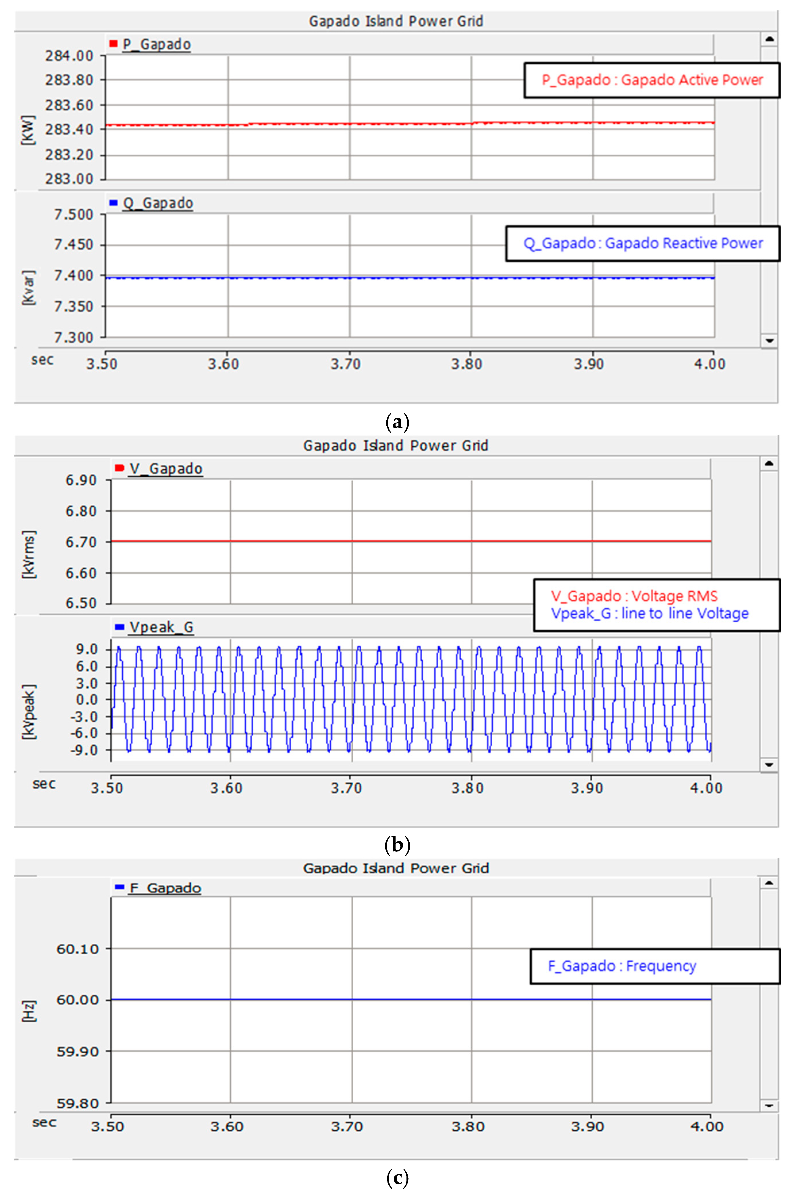
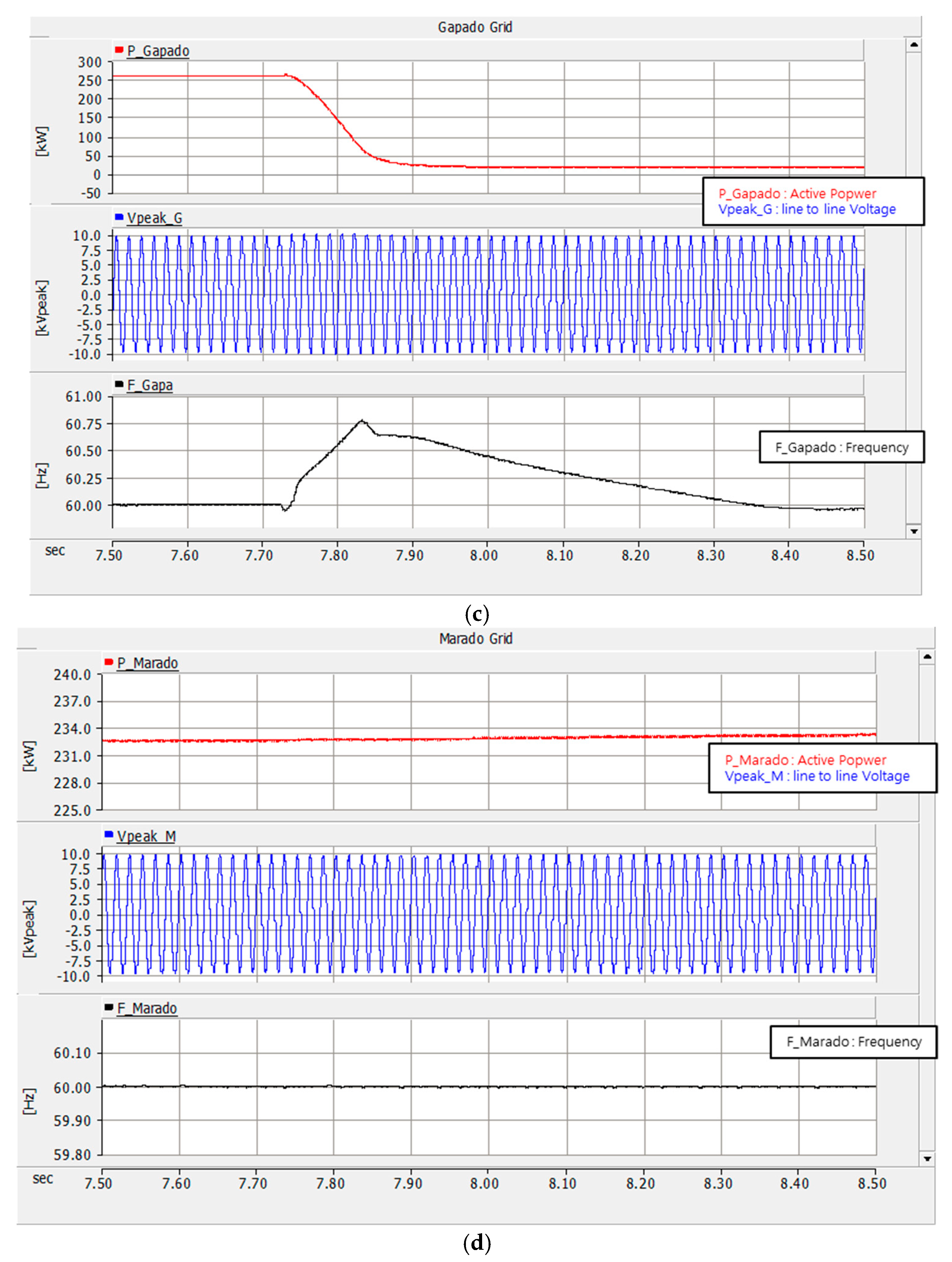
3.1.2. Gapado Island Power Grid

The Gapado Island power grid consists of three 150 kW capacity (one in reserve), a 1 MW PCS with a 2 MWh battery, two SCIG wind turbines with a capacity of 250 kW, and a 141 kW capacity photovoltaic power generation facility. In addition, since the power load has a maximum of 300 kW, corresponding to this, the load model has three resistive capacities of 100 kW. Diesel generators make a relatively small contribution to the power supply because they already have power systems operated by ESS, and solar and wind power generators.
• Steady State
Figure 11a–c show the grid waveforms at steady-state. The criteria for normal conditions are assumed to be the same as in Table 2:
The nominal grid voltage of Gapado Island is 6.9 kV, but it drops to 6.7 kV due to transformer and other line losses when active power is generated in the diesel generator and supplied to the power grid.

3.2. Interpreting the Proposed Microgrid Computer

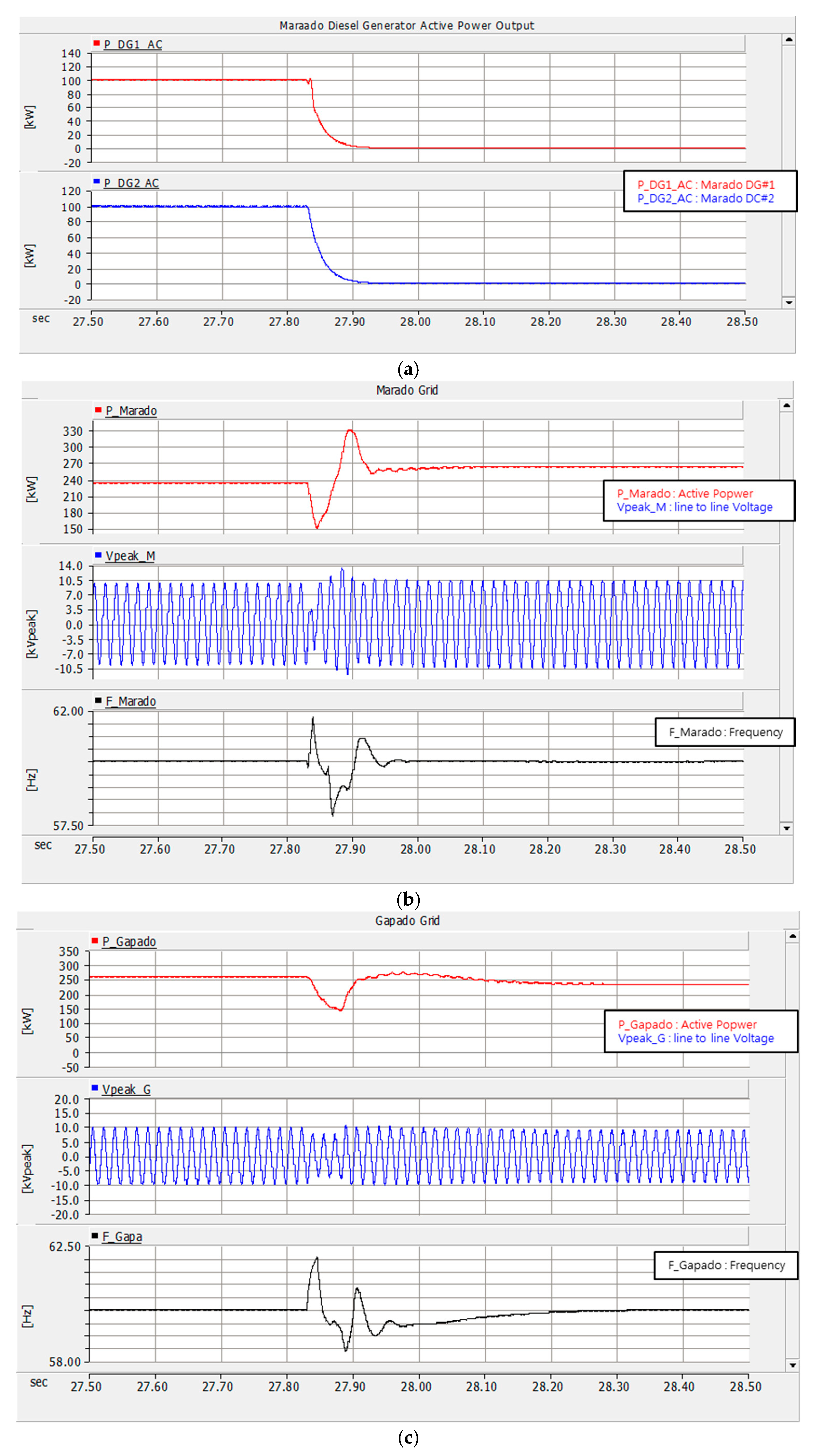
3.2.1. The Marado Island Power Grid

This has the same structure as the current power grid, because it aimeds to maintain the existing power system as much as possible and to operate it optimally. In addition, the already installed 150 kW photovoltaic system is operated irrespective of the power system situation. In this case, when the generated power is surplus or insufficient, the power system is maintained by supplying or receiving the power with the MVDC. Section 3.2.3 shows the related simulation results.

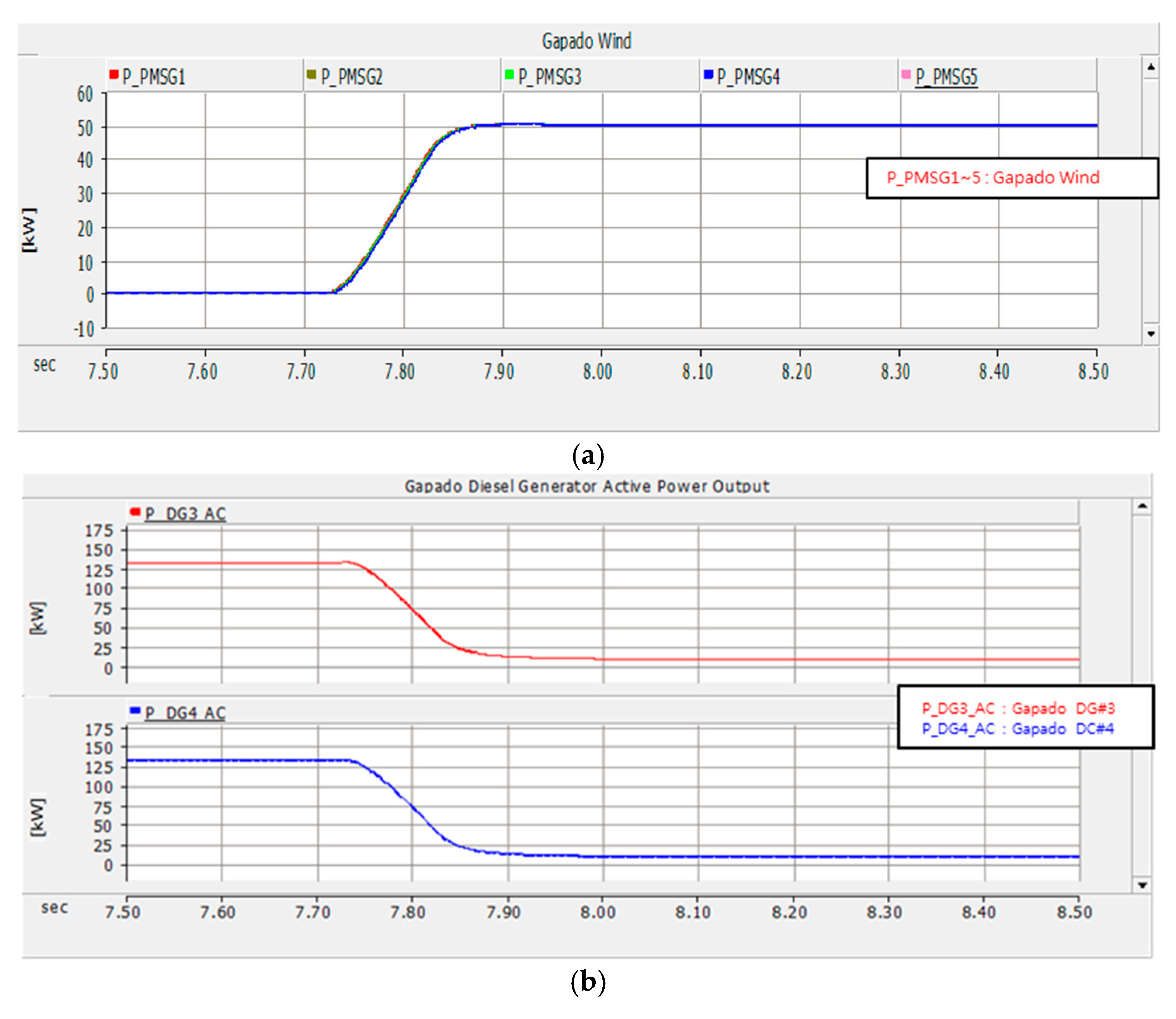
3.2.2. The Gapado Island Power Grid

Figure 12a–d show the simulation results using the proposed power system of Gapado Island. When the two diesel generators installed on Gapado Island drop out, the 1 MW PCS with a 2 MWh battery is switched to emergency mode in normal mode by applying the same method as MVDC operation to prevent power system shutdown on the island. As shown in Figure 12a, the active power output of the two diesel generators is 150 kW each. It has a 1 MW PCS with a 2 MWh battery and controls the active power output of the diesel generator in normal mode, so it supplies a certain amount of active power to the system. In this case, when two diesel generators are dropped out at the same time, the diesel generator # 5 and 1 MW PCS with a 2 MWh are operated as shown in Figure 12b. MVDC operation mode is switched to emergency mode, and is controlled by CVCF mode. As shown in Figure 12c,d, the voltage and frequency of the power grid are reduced to 57 Hz at the moment of interruption, but the power system is restored to its normal state quickly without collapse.
Figure 12a, shows that the active power of the two diesel generators is 150 kW each. This is because the active power of the diesel generator is controlled in 1 MW PCS with a 2 MWh battery. When two diesel generators are dropped out, the diesel generator # 5 and the 1 MW PCS with a 2 MWh battery are operated, and the system is switched to the emergency mode and operated by CVCF, which controls the voltage and frequency of the power system (Figure 12b). As a result, the voltage and frequency of the power grid drop to 4 kV and 57 Hz, respectively. But it can be confirmed that the power system is restored to its normal state quickly without collapsing.

3.2.3. Microgrid According to the Proposed MVDC Links

In order to verify the validity of the proposed microgrid in the MVDC connection between Gapado Island and Marado Island, computer simulations are carried out according to the following three scenarios and the results are discussed.

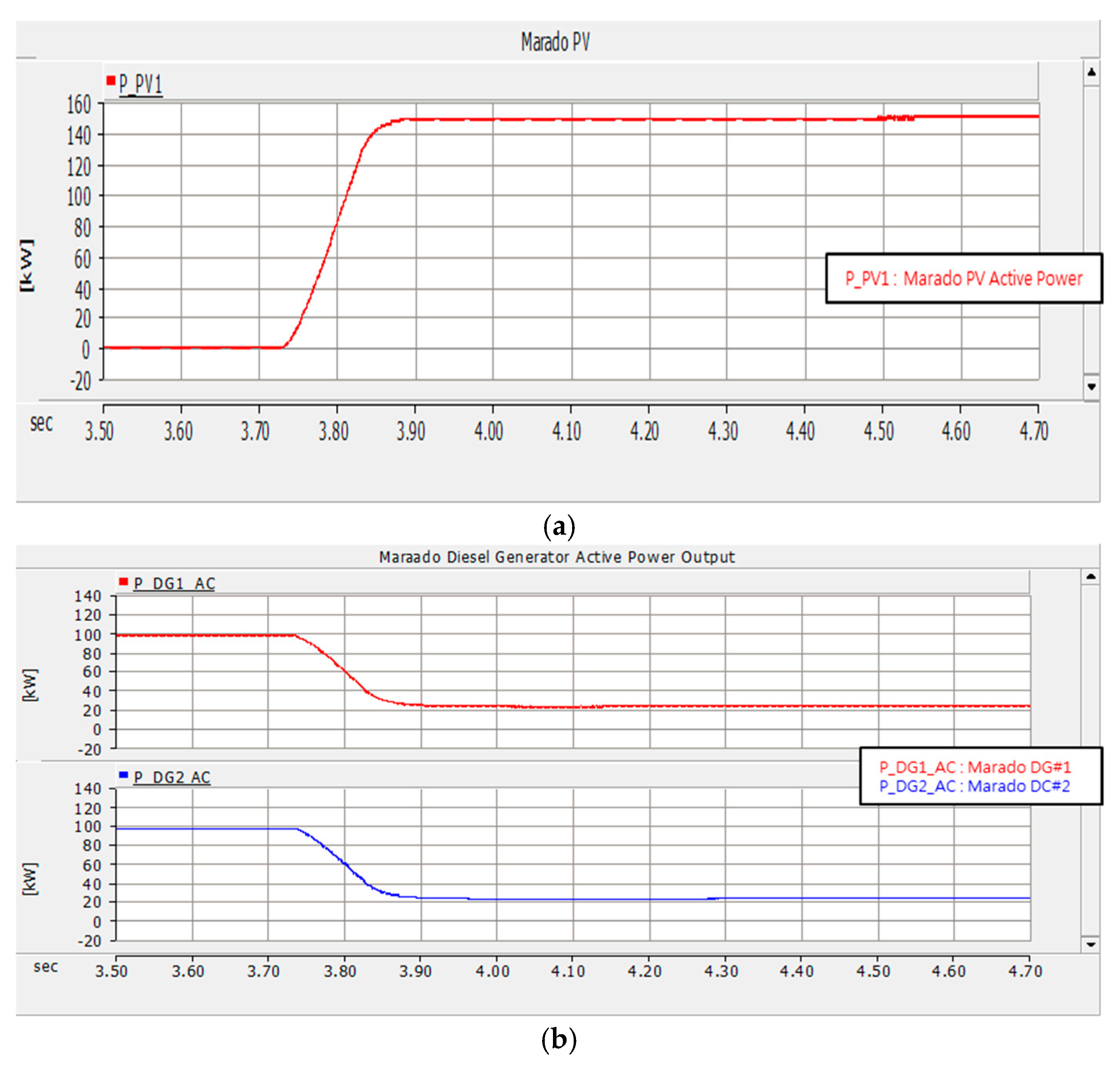
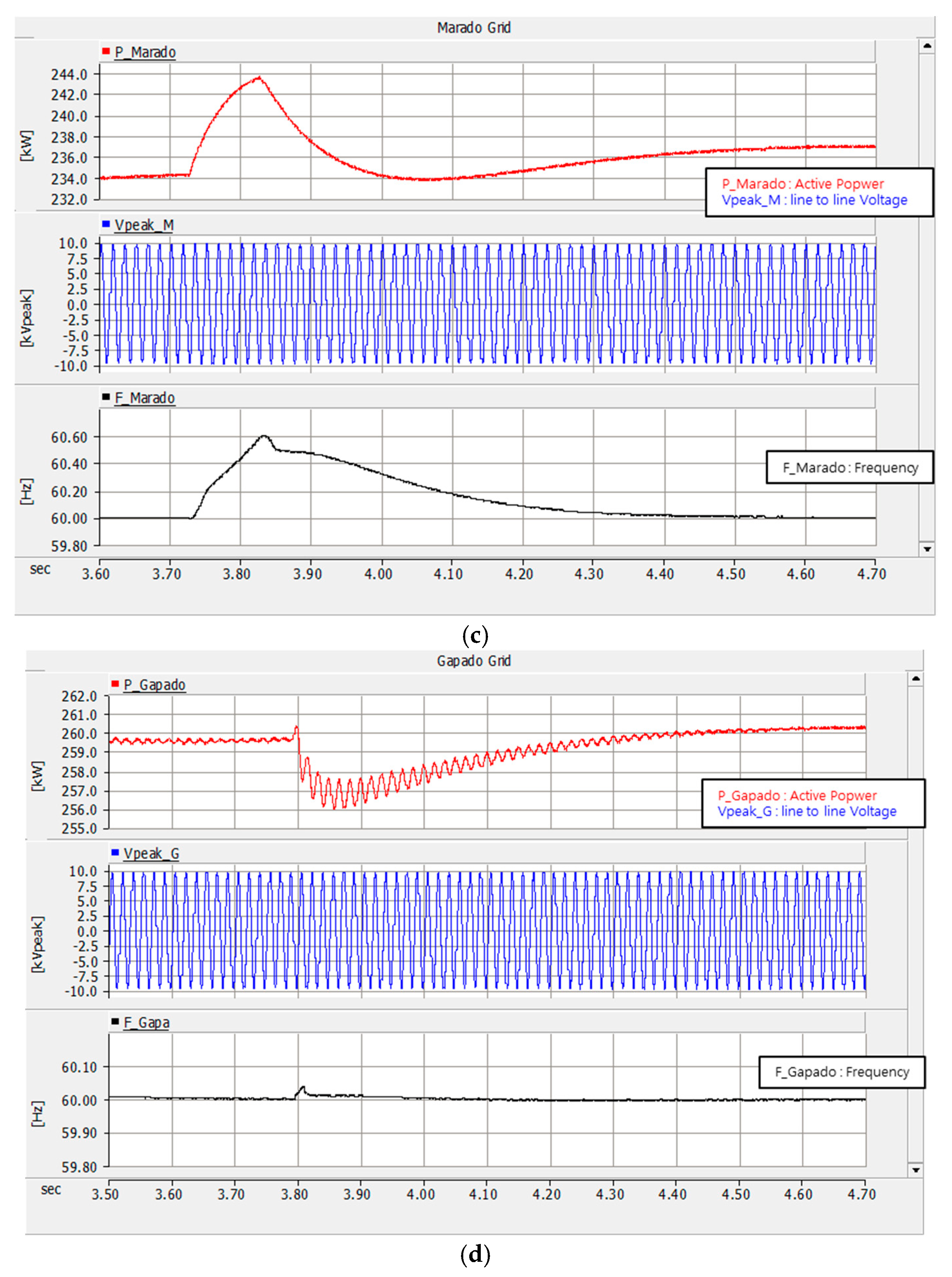
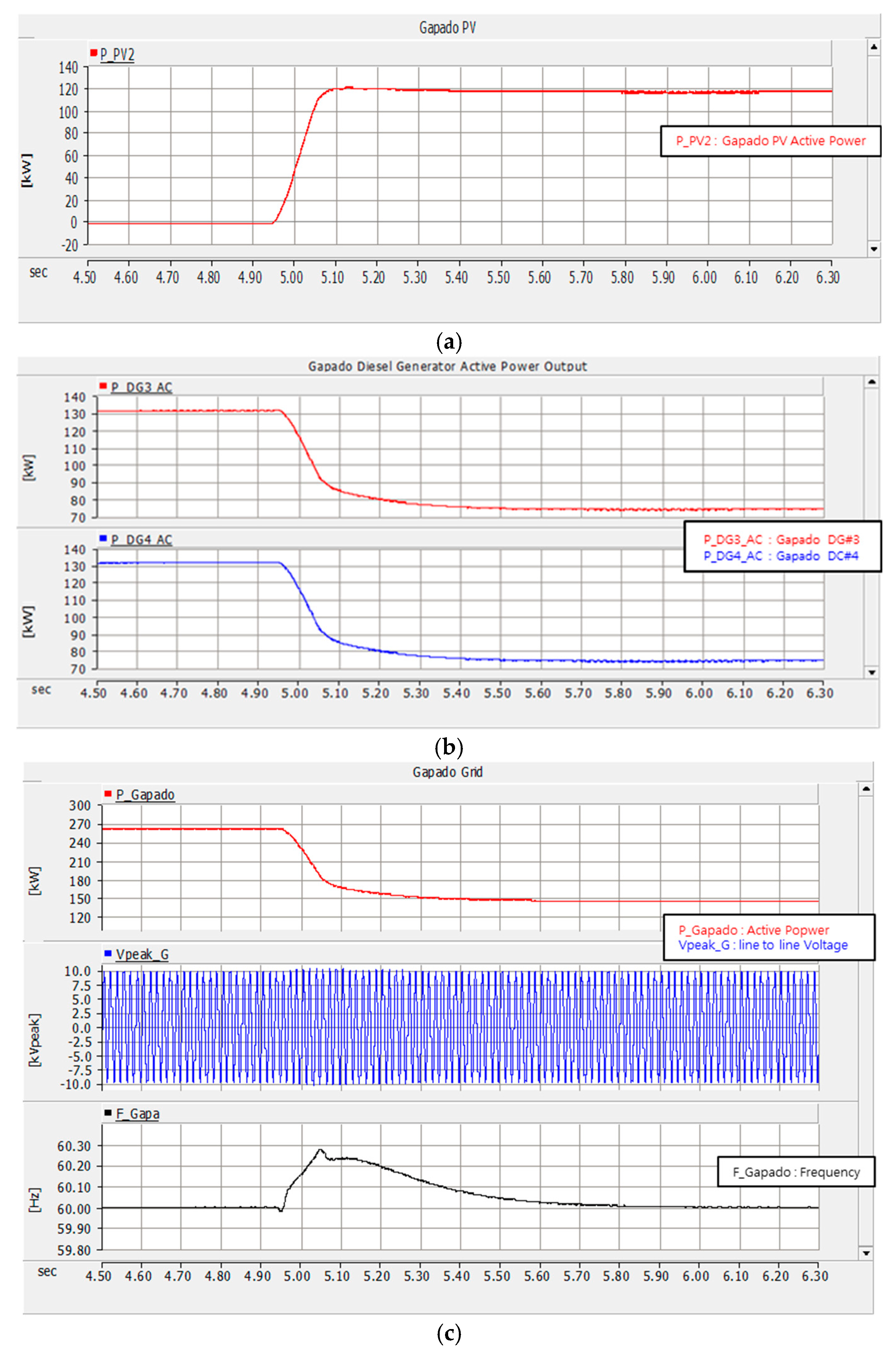
Scenario 1: PV penetration in Marado Island and Gapado Island

Figure 13 shows the output characteristics of the Marado grid and diesel generator according to the 150 kW PV output. Figure 13a shows that the 150 kW PV installed on Marado Island is supplying the maximum power to the power grid. Figure 13b shows that the output of the two diesel generators operated at this time decreases the output of the diesel generator as much as the PV penetration. Figure 13c shows the state of active power, voltage, and frequency in the power grid of Marado Island. It can be seen that the frequency of the power grid temporarily rises to 60.6 Hz instantaneously at the moment of PV penetration, but returns to steady state quickly. Figure 13d shows that the maximum power of the PV and operating on Marado Island does not affect the power grid of Gapado Island.
Figure 14a shows that the 141 kW PV installed in Gapado Island is supplying the maximum power to the power grid. Figure 14b shows that the output of the two diesel generators operated at this time decreases the output of the diesel generator as much as the PV penetration. Figure 14c shows the state of active power, voltage, and frequency in the power grid of Marado Island. It can be seen that the frequency of the power grid temporarily rises to 60.3 Hz instantaneously at the moment of PV penetration, but returns to the steady state quickly. Figure 14d shows that the maximum power of the PV and operating on Gapado Island does not affect the power grid of Marado Island.

Scenario 2: Penetration of wind power generation on Gapado Island

Figure 15a shows the output of total wind power generation on Gapado Island. Figure 15b shows that the power output of diesel generators decreases according to the output of the wind turbines. As a result, it is possible to estimate the power quality of the Gapado Island grid as shown in Figure 15c. At the moment of penetration of the wind generator, the frequency of the grid rises to 60.8 Hz per second but quickly returns to normal. Figure 15d shows that the wind generator in Gapado Island has no effect on the Marado Island grid at full power.

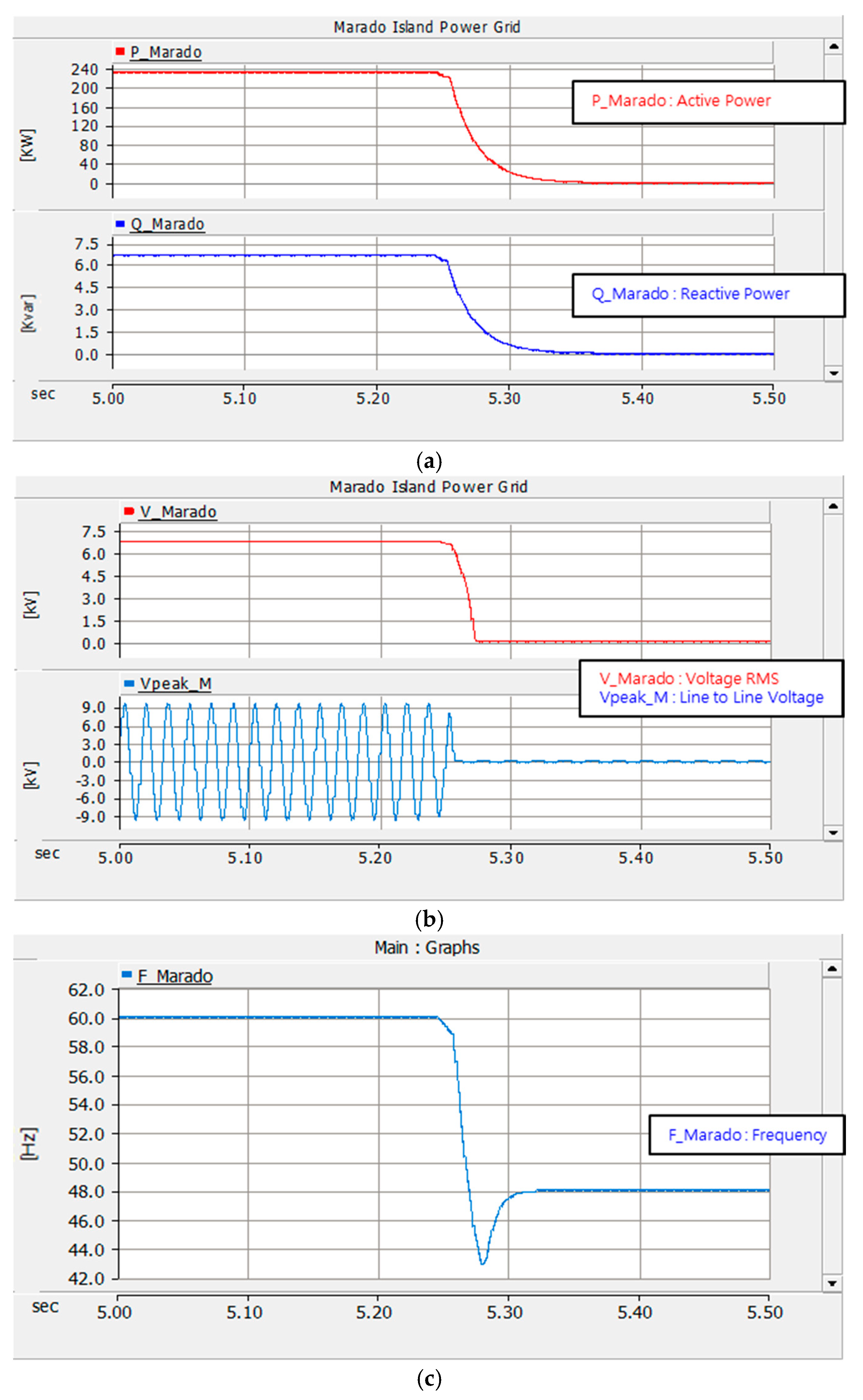
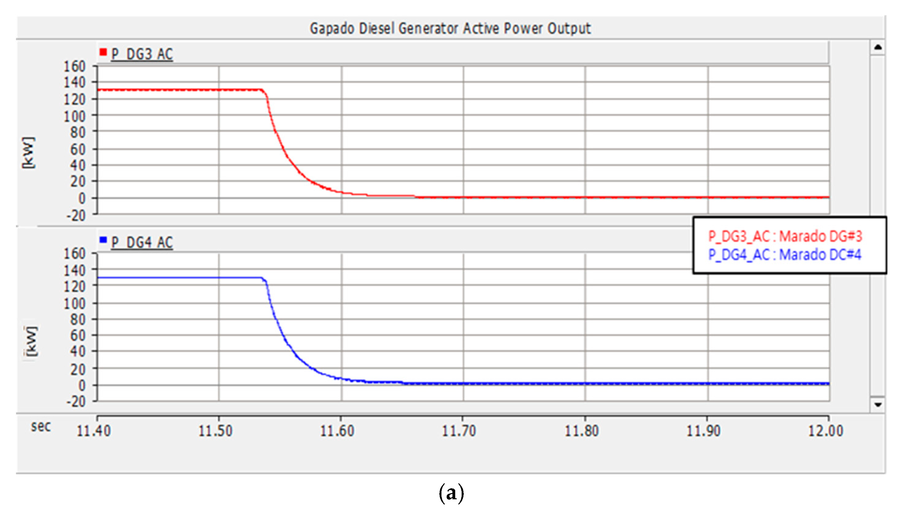
Scenario 3: Marado Diesel Generator Outage

Figure 16a shows a waveform in which two diesel generators suddenly dropout when a diesel generator in Marado Island is supplying power to the power grid. At this time, the MVDC changes from normal mode to emergency mode, confirming that the active power, voltage, and frequency (59~61 Hz) of the power grid are quickly returned to the normal state (Figure 16b). Figure 16c shows the state of the active power, voltage, and frequency of the grid on Gapado Island due to diesel generator shutdown on Marado Island. At this time, the MVDC is switched from normal mode to emergency mode. It can be seen that voltage and frequency fluctuations have occurred but return to normal steady state. Figure 16c also shows that there is no change in the power system of Gapado Island due to the diesel generator shutdown on Marado Island [16].

4. Conclusions

In this paper, we propose a stand-alone microgrid scheme that can stabilize the power system of the two islands by connecting MVDC between Gapado Island and Marado Island in South Korea. To verify the validity of the proposed scheme, computer simulation was carried out with the PSCAD/EMTDC program. The results are as follows:
(1)
A stand-alone microgrid with a small-scale power system, is composed mostly of renewable generation facilities such as solar, wind power, and diesel generator. In this configuration, it can be confirmed that the system can be operated more stability than the existing operation scheme when the system is operated by spreading two islands with small system capacity with the MVDC.
(2)
It can be confirmed that the collapse of the power system can be prevented even when the renewable energy source or the main power source is penetrated or removed.
(3)
It is expected that if the isolated island adjacent to a large power system is operated in conjunction with MVDC, it will not only expand the penetration of distributed generation sources such as renewable energy, but also contribute to the stabilization of the power system.

Author Contributions

Conceptualization, E.-H.K. and J.A.; methodology, E.-H.K.; software, J.A.; validation, E.-H.K., J.A.; formal analysis, J.A.; investigation, E.-H.K.; resources, J.A.; data curation, J.A.; writing—original draft preparation, J.A.; writing—review and editing, J.A.; visualization, E.-H.K.; supervision, J.A.; project administration, E.-H.K.; funding acquisition, E.-H.K.

Funding

This research was funded by the Korea Electic Power Corporation. (Grant number: R18XA03).

Acknowledgments

This work was supported by the Korea Electic Power Corporation. (Grant number: R18XA03) and the Korea Institute of Energy Technology Evaluation and Planning (KETEP) and by the Ministry of Trade, Industry & Energy (MOTIE) of the Republic of Korea (No. 20174030201490).

Conflicts of Interest

The authors declare no conflict of interest.

References

  1. Dujic, D.; Christe, A. Galvanically Isolated High Power Converters for Power Converters for MVDC Applications; ADCGS: Aachen, Germany, 2018; pp. 3–7. [Google Scholar]
  2. GE Power Conversion. Available online: https://www.gepowerconversion.com/press-releases/ge-supports-power-grids-future-europe%E2%80%99s-first-mvdc-link (accessed on 21 June 2017).
  3. Wan, K.D. A Study on the Improvement Scheme of Distributed Generation Facilities in Gapado Island Power Grid. Master’s Thesis, University of Jeju, Jeju City, Korea, 2014. [Google Scholar]
  4. Song, S.H.; Kwon, T.H. Firing angle control of soft starter for reduction of inrush current during grid connction of induction-type wind generator. Trans. KIEE 2005, 10, 397–402. [Google Scholar]
  5. Lee, J.H.; Shim, M.B.; Lee, H.Y.; Han, B.M.; Yang, S.C. Operational analysis of energy storage system to improve performance of wind power system with induction generator. Trans. KIEE 2009, 58, 1138–1145. [Google Scholar]
  6. Kim, D.W.; Ko, J.H.; Kim, S.H.; Kim, H.; Kim, E.H. Renewable energy configuration plan of micro grid in Gapa Island. Kisti 2014, 34, 16–23. [Google Scholar]
  7. Son, J.M.; Park, J.H.; Song, J.D. Independent Micro Grid Demonstration Site Engineering Engineering Development. Final Rep. 2013, 5, 63–67. [Google Scholar]
  8. Sahoo, S.K.; Sinha, A.K.; Kishore, N.K. Control techniques in AC, DC, and hybrid AC–DC microgrid: A review. IEEE J. Emerg. Sel. Top. Power Electron. 2018, 6, 738–759. [Google Scholar] [CrossRef]
  9. Heyman, O.; Weimers, L.; Bohl, M. HVDC—A Key Solution in Future Transmission Systems; WEC: Montreal, QC, Canada, 2010. [Google Scholar]
  10. Deng, W.; Pei, W.; Li, L. Active stabilization control of multi-terminal AC/DC hybrid system based on flexible low-voltage DC power distribution. Energies 2018, 11, 502. [Google Scholar] [CrossRef]
  11. Yazdami, A.; Iravani, R. Voltage-Sourced Converters in Power System; Willy-IEEE Press: Hoboken, NY, USA, 2010; Volume 17, pp. 91–107. [Google Scholar]
  12. Thinh, Q.N. Control of MMC-HVDC System and Its Application to the Jeju Island Power System. Ph.D. Thesis, University of JEJU, Jeju City, Korea, 2014. [Google Scholar]
  13. Sood, V.K. HVDC and FACTS Controllers; Kluwer Academic Publishers: Boston, MA, USA, 2004. [Google Scholar]
  14. Mura, F.; De Doncker, R.W. Design aspects of a medium-voltage direct current (MVDC) grid for a University Campus. J. ICPE 2011, 5, 2359–2366. [Google Scholar]
  15. Chung, I.Y.; Liu, W.; Carters, D.A.; Cho, S.H.; Kang, H.K. Controller optimization for bidirectional power flow in medium-voltage DC power systems. J. Electr. Eng. Technol. 2011, 6, 750–759. [Google Scholar] [CrossRef]
  16. Hosseinazdeh, M.; Salmasi, F.R. Fault-tolerant supervisory controller for a hybrid ac/dc micro-grid. IEEE Trans. Smart Grid 2018, 9, 2809–2823. [Google Scholar] [CrossRef]
  17. HVDC-High Voltage Direct Current Transmission. Available online: http://www.energy.siemens.com/hq/pool/hq/power-trnsmission/HVDC/HVDC-Classic_Transmission_References_en.pdf (accessed on 21 June 2017).
  18. Alstom. HVDC-VSC: Transmission TechnolTogy of the FuturFe. Available online: http://www.alstom.com/Global/Grid/Resources/Documents/Smart%20Grid/Think-Grid-08-%20EN.pdf (accessed on 21 June 2017).
  19. Jeong, J.K.; Jung, H.J.; Yoo, H.H.; Park, Y.H.; Lee, D.Y. Commissioning test of the MMC (modular multi-level converter) type 25mva HVDC pilot project. KIEE 2013, 62, 2. [Google Scholar]
  20. Jeong, J.K.; Jung, H.J.; Yoo, H.H.; Park, Y.H.; Lee, D.Y. MMC (Modular multi-level converter) type 25MVA HVDC system test. J. Power Electron. 2017, 7, 282–283. [Google Scholar]
  21. Hong, J.W.; Jeong, J.K.; Yoo, S.H.; Choi, J.Y.; Han, B.M. Switching-level operation anaysis of MMC-based back-to-back converter for HVDC application. KIEE 2013, 62, 9. [Google Scholar]
Figure 1. The existing Gapado Island Power Grid.
Energies 12 00187 g001
Figure 2. The Proposed Gapado Island Power Grid.
Energies 12 00187 g002
Figure 3. The existing Marado Island Power Grid.
Energies 12 00187 g003
Figure 4. The proposed MVDC connection between Gapado Island and Marado Island.
Energies 12 00187 g004
Figure 5. Circuit diagram of the proposed MVDC system.
Energies 12 00187 g005
Figure 6. Control diagram of the current.
Energies 12 00187 g006
Figure 7. Control diagram of the DC-Link voltage.
Energies 12 00187 g007
Figure 8. Microgrid composition of Gapado Island and Marado Island through MVDC Linkage.
Energies 12 00187 g008
Figure 9. (a) Power (active and reactive); (b) voltage (Peak and RMS); (c) frequency waveform in steady state.
Energies 12 00187 g009
Figure 10. (a) Power; (b) voltage; (c) frequency; waveform in diesel generator outage.
Energies 12 00187 g010
Figure 11. (a) Power; (b) voltage; (c) frequency; waveform in steady state.
Energies 12 00187 g011
Figure 12. (a) Active power; (b) active power of 1 MW PCS; (c) voltage; (d) frequency; simulation results of Gapado Island when under diesel generator dropout.
Energies 12 00187 g012aEnergies 12 00187 g012b
Figure 13. (a) Active power output of grid; (b) Variation of active power of diesel generator; (c) Marado Island power grid; (d) Gapado Island power grid; through the PV penetration.
Energies 12 00187 g013aEnergies 12 00187 g013b
Figure 14. (a) Active power output of the grid; (b) Variation of active power output of the diesel generator; (c) Gapado Island power grid; (d) Marado Island power grid; through the PV penetration.
Energies 12 00187 g014aEnergies 12 00187 g014b
Figure 15. (a) Active power; (b) Variation of active power of diesel generator; (c) Gapado Island power grid; (d) Marado Island power grid; through the Wind power penetration.
Energies 12 00187 g015aEnergies 12 00187 g015b
Figure 16. (a) Active power output of diesel generator; (b) Variation of Marado Island power grid; (c) Variation of Gapado Island power grid; through the Marado Island diesel fault [17,18,19,20,21].
Energies 12 00187 g016
Table 1. Marado Island Grid Parameters.
Parameters Voltage   ( k V r m s ) Reactive (kvar)Active (kW)Frequency (Hz)
Grid6.786.6323160
Table 2. Marado Island Power Grid Parameters.
Parameters Voltage   ( k V r m s ) Reactive (kvar)Active (kW)Frequency (Hz)
Grid6.77.39428360

