Article

A Novel Direct Torque Control Method Based on Asymmetric Boundary Layer Sliding Mode Control for PMSM

Beijing Co-innovation Center for Electric Vehicles, Beijing Institute of Technology, Beijing 100081, China
*
Author to whom correspondence should be addressed.
Energies 2018, 11(3), 657; https://doi.org/10.3390/en11030657
Submission received: 20 January 2018 / Revised: 8 March 2018 / Accepted: 8 March 2018 / Published: 15 March 2018
(This article belongs to the Special Issue The International Symposium on Electric Vehicles (ISEV2017))

Abstract

:
A novel direct torque control (DTC) method based on sliding-mode-control (SMC) strategy is proposed for permanent magnet synchronous motor (PMSM) which is used in electric vehicles (EVs). In order to improve the dynamic response time and enhance the robustness performance against the external loading disturbances and motor parameter’s variation, a kind of SMC-based torque controller and speed controller are designed to regulate the torque angle increment and the speed respectively. The torque controller is designed based on a sliding mode controller with an asymmetric boundary layer to reduce the overshoot. Compared with other DTC methods based on space vector modulation (SVM) in the literature, the proposed DTC scheme adopts the asymmetric boundary layer SMC instead of the proportional-integral (PI) regulator. The simulation results have validated the effectiveness of the proposed SMC-based DTC method.

1. Introduction

In recent years, the study on Electric Vehicles/Hybrid Electric Vehicles (EVs/HEVs) has warmed up due to the serious air pollution and the stringent regulations on emissions as well as constraints on energy resources. For the electric propulsion systems in EVs/HEVs, permanent magnet synchronous motors (PMSM) are extensively applied owing to the high efficiency, high power density and low maintenance cost [1,2].
There are two common strategies for PMSM, Field-Oriented Control (FOC) and Direct Torque Control (DTC), which can realize the motor’s high-performance operation. Different from the decoupled current control in FOC, the conventional DTC uses two hysteresis regulators and a switching table to control electromagnetic torque and stator flux linkage directly. So DTC strategy possesses the merits of simple implementation, fast dynamic response, and good robustness against motor parameters’ variation and external disturbances. Hence, the DTC is better than FOC for the application of EVs which require high torque response [3]. However, this scheme has several major disadvantages, namely large torque and flux ripples, variable switching frequency and high sampling requirement for digital implementation [4]. To address these problems, numerous modified DTC methods have been proposed from various perspectives. These methods are classified into several categories.
The basic idea is to add more available voltage vectors. The typical approach uses new hardware topologies. In [5], a three-level inverter is employed instead of the classical two-level inverter, hence generating 27 voltage vectors, and 19 of them are non-repetitive. In [6], a three-phase to three-phase matrix converter is employed, and 21 voltage vectors are available in the DTC algorithm. However, in order to use more voltage vectors, the hysteresis controllers must have more output levels. The stator flux vector space is subdivided into more sections and the switching table is expanded. Therefore, it inevitably increases the complexity and hardware cost of the system.
In the classical DTC method, the voltage vector is utilized in the entire cycle of motor control. If we can control the applied time of the active voltage vectors, the torque control will be more accurate, and the torque and flux ripples can also be suppressed. Based on this thought, duty cycle control is introduced in the DTC, which adjusts the duty ratio of the active voltage vectors. The key point is how to obtain the duty ratio. Varieties of methods are proposed and differ in the optimization objectives for duty cycle determination [7,8,9]. The method in [7] determines the duty ratio on the basis of torque ripple RMS (Root-Mean-Square) minimization over one cycle. In [8], direct mean torque control forces the mean torque equal to the reference value in one cycle. The author in [9] simplifies the algorithm of duty cycle determination. He applies two adjacent active voltage vectors to the motor control in each cycle, which can regulate the torque and flux precisely. In these strategies, many motor parameters are used to calculate the torque slopes. Hence, the robustness of the system is deteriorated and computation burden is increased. Furthermore, according to the condition where one unique duty determination is used under different speed and torque, there always exists significant steady error of torque.
Another category of the enhanced DTC schemes is incorporated of space vector modulation (SVM). SVM-based DTC can generate voltage vectors with adjustable amplitude and phase, so it can control the electromagnetic torque and stator flux more precisely. As a result, two main advantages can be realized, namely, torque and flux ripples reduction and the fixed switching frequency. The core issue of this strategy is how to obtain the reference voltage vector. There are several different methods in this respect, such as deadbeat controller [10], torque predictive controller [11] and proportional-integral controller [12].
The aforementioned strategies are proposed to achieve high-performance torque control, but speed regulation is also important in traction applications. For instance, the speed control performance of the electric motor has a great influence on the entire gear shifting process in the clutchless automatic mechanical transmission systems [13]. In general, the PI controller is adopted in the speed loop for improved DTC methods due to its simplicity and clear functionality [14]. However, a big drawback of the PI controller is that the optimal PI control parameter is depend on the system itself and sensitive to the system uncertainties. As a result, the system variations degrade the control performance dramatically. To overcome this disadvantage, the sliding mode controller is used instead of PI controller in electric drives. It features fast response, disturbances rejection and simple implementation.
This paper not only optimize the torque control in the DTC method, but also focuses on the speed regulation. In order to reduce the torque ripples and fix the switching frequency, the SVM technique is adopted, which an arbitrary reference voltage vector can be synthesized with two adjacent primary voltage vectors and one zero voltage vector. Moreover, a SMC-based torque controller is used to regulate the torque angle increment, and a novel SMC-based speed controller is designed instead of a classical PI controller. Consequently, the proposed scheme improves the dynamic response time and enhances the robustness performance against parameter variations and external loading disturbances.
The rest of this paper is organized as follows: Section 2 presents the principle of the conventional DTC for PMSM. In Section 3, the improved DTC method is proposed and analyzed in details. The basic control performance of the conventional and proposed schemes are studied and compared through simulations in Section 4. This paper is concluded with a summary in Section 5.

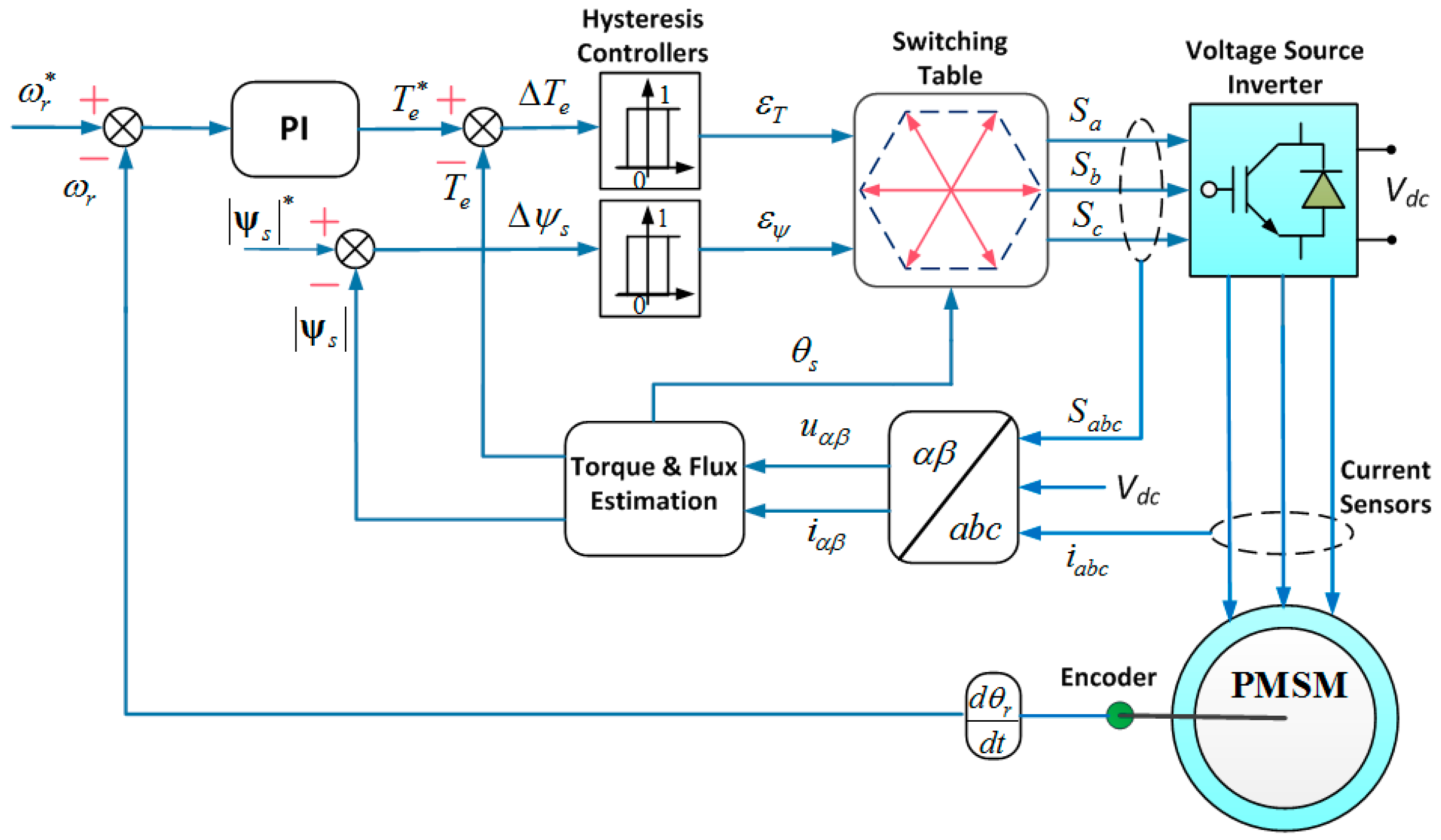
2. Review of Classical DTC for PMSM

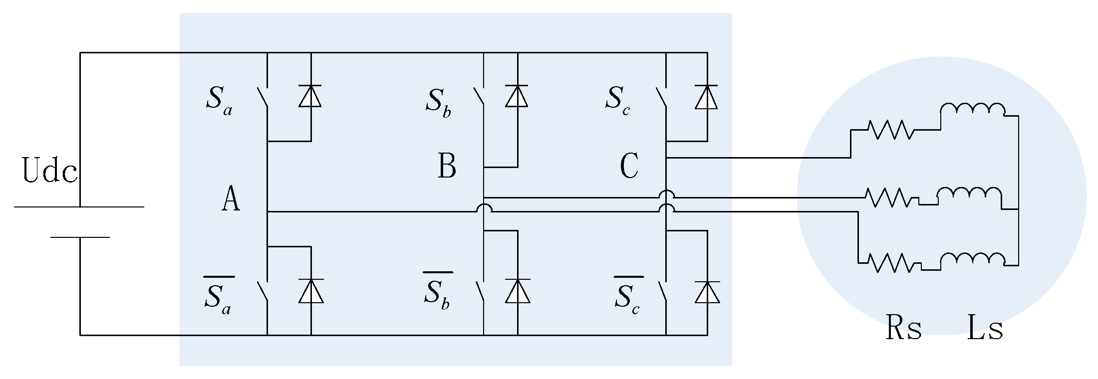
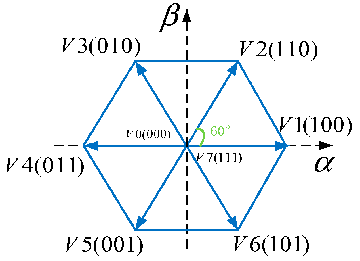
2.1. The Definition of Primary Voltage Vectors

The primary voltage vector V s for a three-phase machine with balanced sinusoidal distributed stator windings is defined by the following equation:
V s = 2 3 ( v α + v b e j 2 π 3 + v c e j 4 π 3 ) ,
where v α , v b and v c are the instantaneous values of the line-to-neutral voltages.
For the two-level voltage source converter (VSC)-fed PMSM system, as shown in Figure 1, the primary voltages v α , v b and v c are determined by the status of the three switches S α , S b and S c . Therefore, there are six active voltage vectors and two zero voltage vectors. The spatial placement of these eight voltage vectors in the α-β stationary reference frame is shown in Figure 2, and they can be expressed as:
V s ( S a S b S c ) = 2 3 U D C ( S a + S b e j 2 π 3 + S c e j 4 π 3 ) ,
where U D C is dc-link voltage.

2.2. Model of PMSM

The voltage and flux equations for a PMSM in the rotor d-q rotating coordinate can be described as the following equations:
{ u s d = R s i s d + d ψ s d d t p m ω r ψ s q u s q = R s i s q + d ψ s q d t + p m ω r ψ s d ,
{ ψ s d = L d i s d + ψ f ψ s q = L q i s q ,
where
  • u s d , u s q —stator voltage of d and q-axis,
  • i s d , i s q —stator current of d and q axis,
  • ψ s d , ψ s q —stator flux linkage of d and q-axis,
  • L d , L q —inductances of d and q-axis,
  • R s —stator resistance,
  • ψ f —permanent magnet flux, and
  • ω r —rotor mechanical speed.
And the electromagnetic torque equation is expressed as:
T e = 3 2 p m ( ψ s d i s q ψ s q i s d ) ,
where p m is the number of pole pairs.
So the dynamic equation is given as:
J d ω r d t = T e T L B ω r ,
where J is moment of inertia, T e is motor torque load, and B is coefficient of viscous friction.
The torque equation in terms of δ and other motor parameters is given by:
T e = 3 4 p m | ψ s | L d L q [ 2 ψ f L q sin δ | ψ s | ( L q L d ) s i n ( 2 δ ) ]
where | ψ s | is the magnitude of the stator flux linkage.
For a surface PMSM, namely, L d = L q = L s , the equation can be simplified as:
T e = 3 p m 2 L s | ψ s | ψ f sin δ
From this equation, the torque can be controlled directly by regulating the torque angle δ if the amplitude of the ψ s is kept constant. Furthermore, the torque increases with the increase of δ .

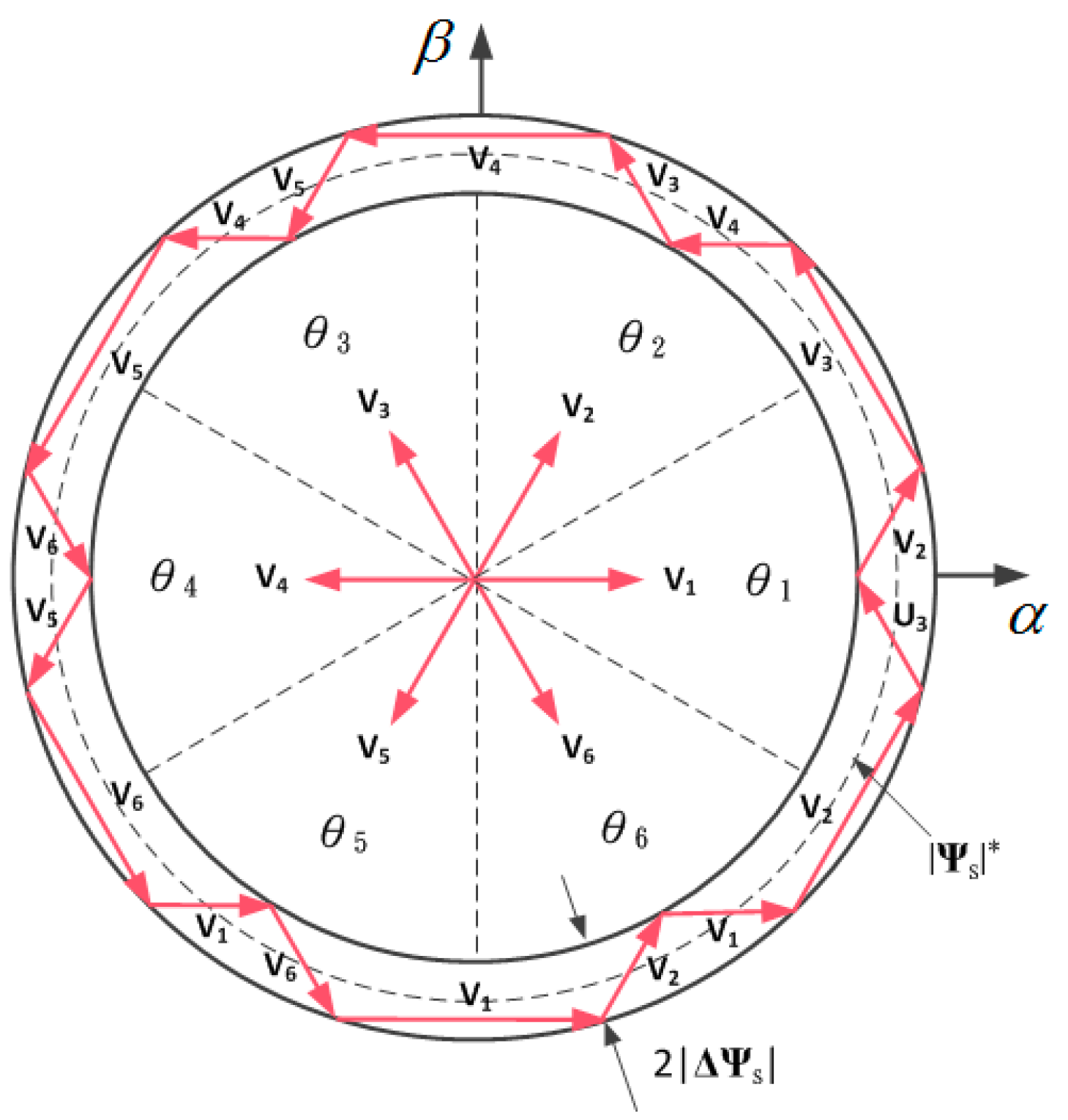
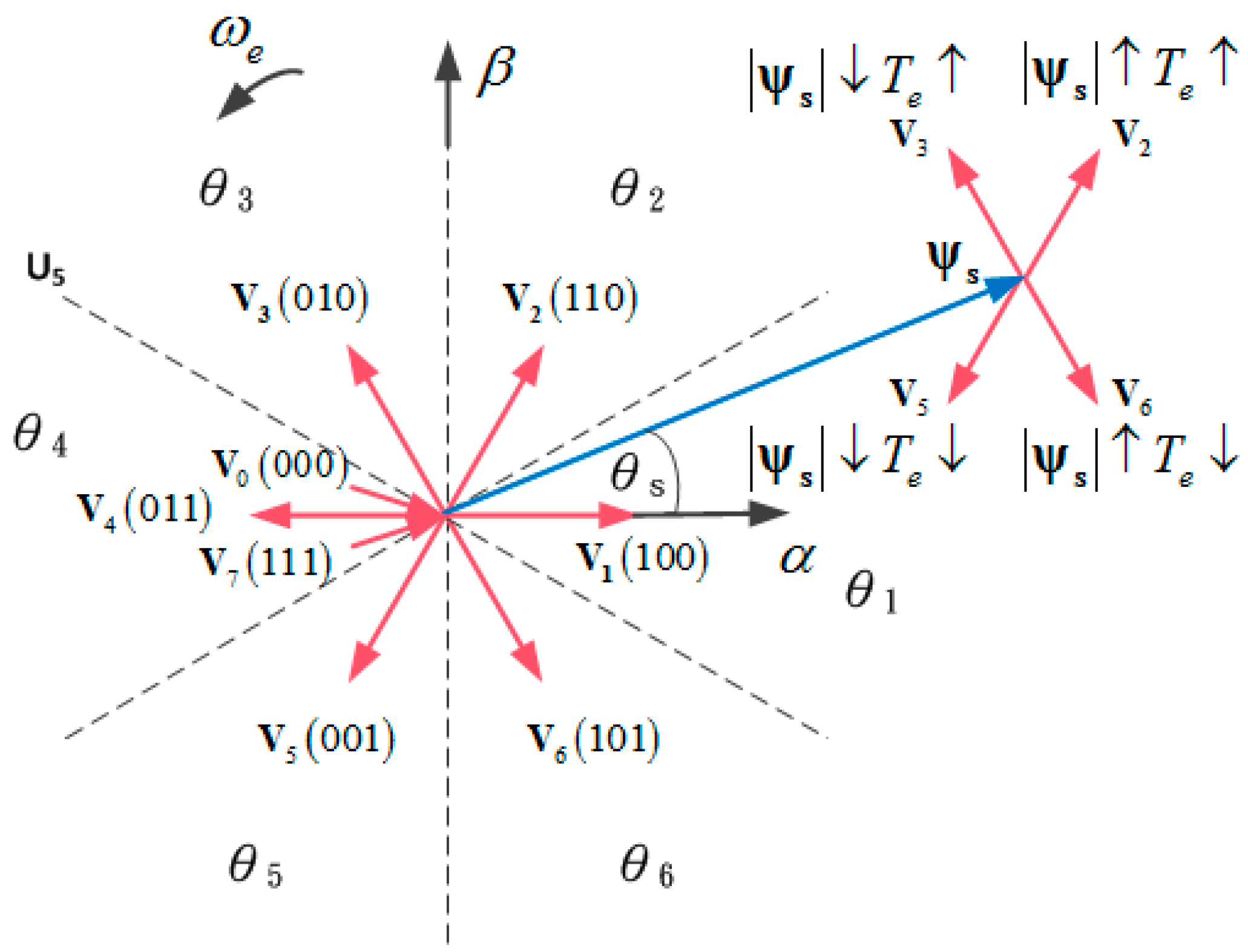
2.3. The Control of the Amplitude of Stator Flux Linkage

The stator flux linkage in the α-β stationary reference frame can be expressed as
ψ s = ( u s R s i s ) d t .
During the switching interval, every voltage vector can be regarded as constant, and equation can be rewritten as:
ψ s = u s t R s i s d t + ψ s | t = 0 ,
where ψ s | t = 0 is the initial stator flux linkage.
The equation implies that ψ s will move in the direction of the applied voltage vector if the stator resistance is neglected. Therefore, the amplitude of stator flux linkage can be increased or decreased by selecting the proper voltage vector. Figure 3 shows how the voltage vectors are selected for keeping ψ s within a hysteresis band | Δ ψ s | . There are six independent sectors setting in the whole vector plane ( θ i , i = 1–6).
According to above analysis, torque and stator flux can be controlled directly by selecting an appropriate inverter voltage vector to regulate the torque and flux within their respective hysteresis bands. The illustration of the voltage vector’s effects on the stator flux and torque is shown in Figure 4, which the stator flux vector ψ s is located at sector 1 and rotates anticlockwise. The voltage vector V 2 ( 110 ) can increase the torque and stator flux magnitude simultaneously. The voltage vector V 5 ( 001 ) can reduce both the stator flux magnitude and torque. Applying V 3 ( 010 ) enlarges the torque but decreases the stator flux magnitude. Similarly, V 6 ( 101 ) reduces the torque and increases the stator flux magnitude. The similar results can be extended easily for all the other sectors accordingly.

2.4. Implementation of DTC for PMSM

The standard scheme of DTC for PMSM is shown in Figure 5. The torque and stator flux control signals ε T and ε ψ are generated by torque and flux hysteresis controllers respectively, which are defined as:
ε T = { 1 ,   to   increase   T e 0 ,   to   decrease   T e ,
ε ψ = { 1 ,   to   increase   ψ s 0 ,   to   decrease   ψ s .
The six-vector switching strategy for controlling both the amplitude and rotating direction is shown in Table 1. ε T , ε ψ and the position of stator flux linkage vector are the inputs of the switching strategy. Consequently, the vector of voltage makes the flux rotates and produces the needed torque.
In the α-β stationary reference frame, the components of the stator flux linkage are estimated via
{ ψ s α = 0 t ( u s α R s i s α ) d t + ψ s α | t = 0 ψ s β = 0 t ( u s β R s i s β ) d t + ψ s β | t = 0 ,
where ψ s α | t = 0 and ψ s α | t = 0 are the initial components of the stator flux linkage.
The flux amplitude and its phase are derived from:
| ψ s | = ψ s α 2 + ψ s β 2 ,
θ s = a r c t g ψ s β ψ s α .
The electromagnetic torque is estimated by:
T e = 3 2 P n ( ψ s α i s β ψ s β i s α ) .

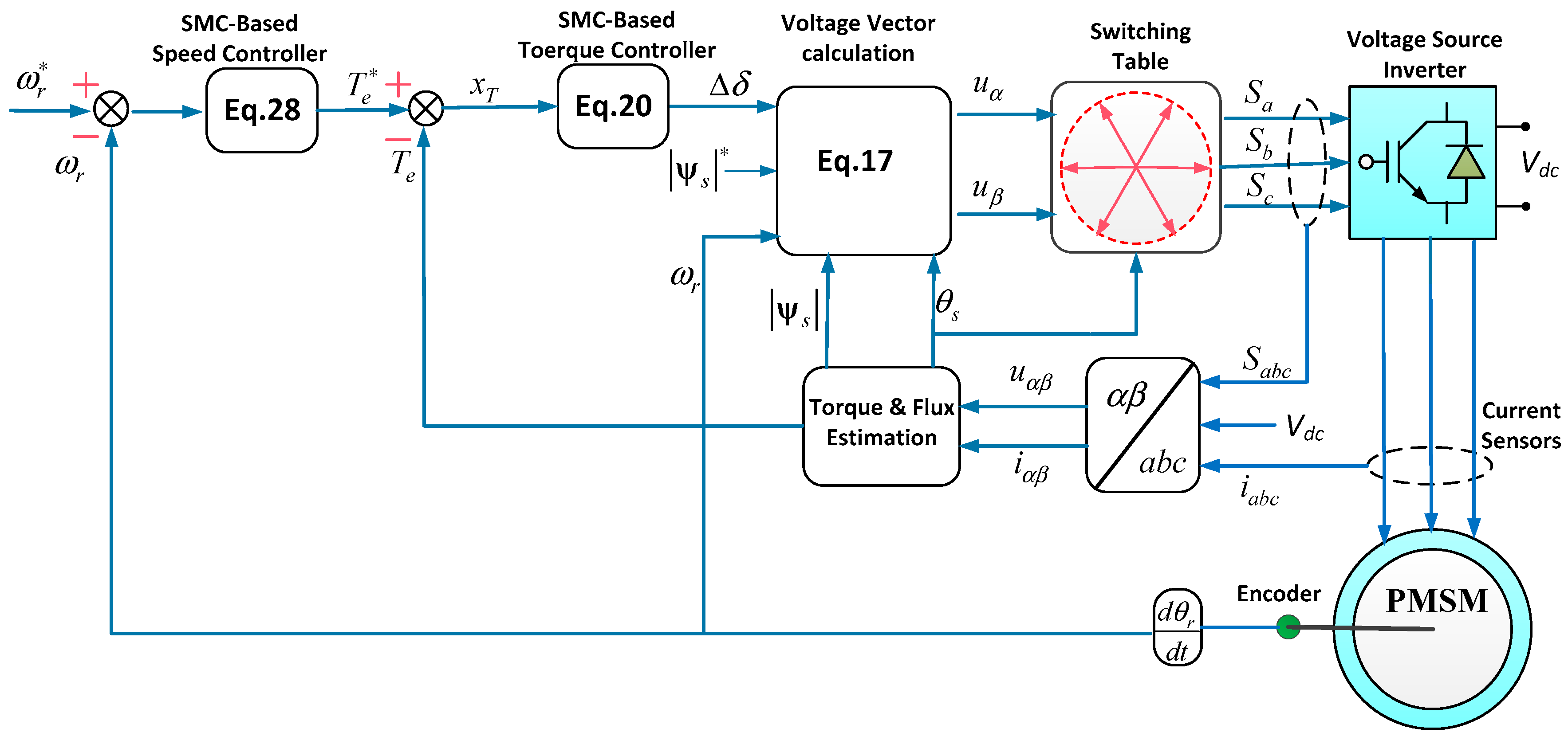
3. Proposed DTC Method

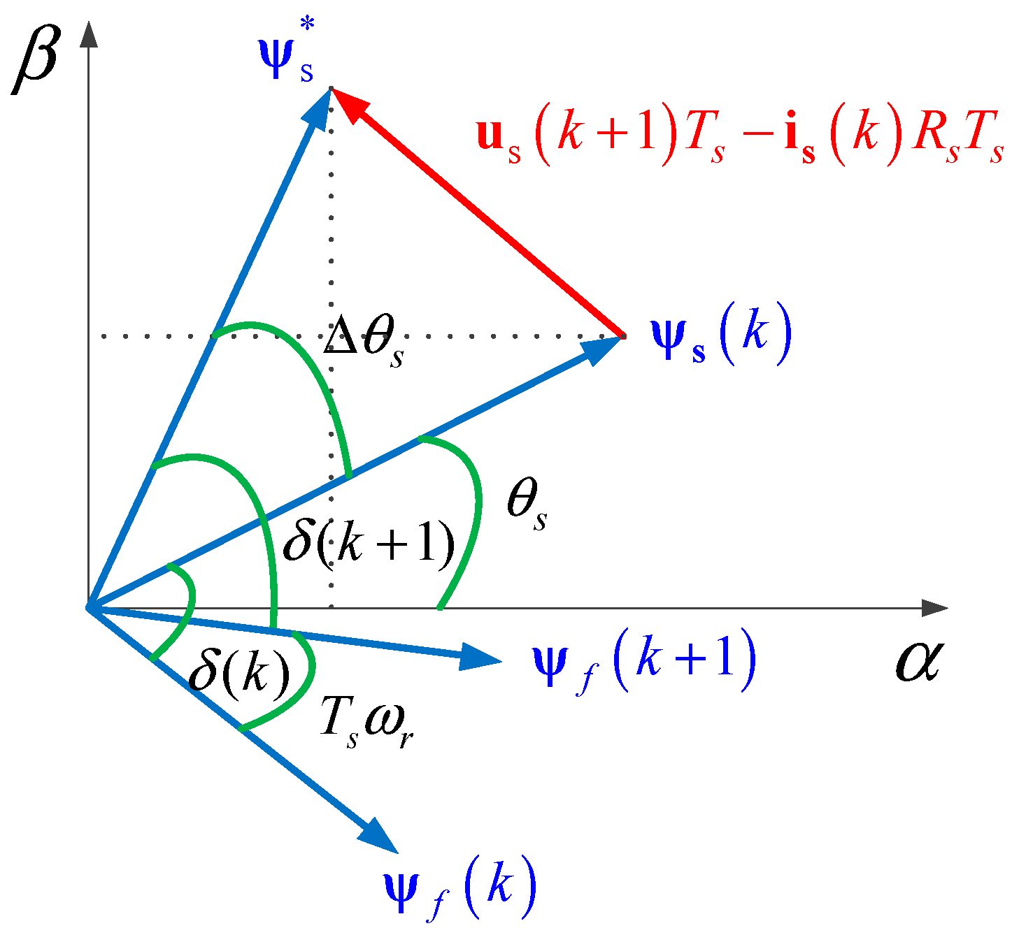
3.1. Generation of Reference Voltage Vector

The conventional DTC uses a limited number of voltage vectors with specific amplitude and fixed direction in each control period, while the SVM-based DTC can synthesize an arbitrary reference voltage vector with multiple vectors in each sampling interval. How to obtain the reference voltage vector is core to the process. In [15,16], the commanding voltage vector can be obtained through the reference stator flux vector in stationary reference frame. The method is named as reference flux vector calculator (RFVC). It calculates the expected voltage vector according to the load angle increment, the estimated position of the stator, and the amplitude of the reference flux linkage.
The stator voltage and its discrete form can be transformed from Equation (9) into the following equation:
u s ( k + 1 ) = ψ s ( k + 1 ) - ψ s ( k ) T s + i s ( k ) R s ,
where T s is the sampling interval. u s ( k + 1 ) is the required voltage vector that forces flux linkage to reach the reference flux linkage vector ψ s at the end of the next sampling interval. Their relationship is shown in Figure 6. Equation (17) can be decomposed in α β reference frame and are rewritten as:
{ u s α ( k + 1 ) = ψ s α * ψ s α T s + i s α ( k ) R s u s β ( k + 1 ) = ψ s β * ψ s β T s + i s β ( k ) R s ,
{ ψ s α * = | ψ s | * cos ( θ s + Δ θ s ) ψ s α = | ψ s ( k ) | cos θ s ψ s β * = | ψ s | * sin ( θ s + Δ θ s ) ψ s β = | ψ s ( k ) | sin θ s Δ θ s = T s ω r p m + Δ δ .

3.2. Design of SMC-Based Torque Controller

From the equation, the relation between the error of torque and the increment of load angel Δ δ is nonlinear. In [15,16], the PI controller is used to generate the load angel increment required to minimize the error between reference T e * and actual torque. However, owing to the characteristic of the PI controller, the performance varies according to the gain and can also be degraded under system uncertainties.
In this paper, a novel SMC-based torque controller is used to regulate the torque angle increment. Its main objective is to control torque of the motor fast and accurately. In the state space, a switching algorithm is used to move the state trajectory onto a selected surface. The sliding surface is chosen to realize the first-order dynamics, the sliding mode operation is followed:
S T = x T + K T x T ,
where x T = T e T e is the torque error, and K T is the positive control gain.
The operation of sliding mode restricts the controlled state onto corresponding sliding surface, namely S T = S T = 0 . The equivalent dynamics can be defined in this condition.
x T = K T x T .
In order to restrain the shock, a boundary layer was set up for the sliding surface and inserted a linear region.
The control law for the load angle increment is selected as:
Δ δ = { u + = Δ θ s max     T s ω r p m i f :   S T > ϕ t + K 1 S T i f : ϕ t < S T < ϕ t + u = Δ θ s max T s ω r p m i f : S T < ϕ t   ,
where K 1 is the proportional gain in the boundary layer and T s is the sampling period. u is the control rate of the SMC. ϕ t is the width of the SMC boundary layer. Δ θ s is restrained by the maximum voltage vector of the electric power capacity.
Δ θ s max is the maximum flux linkage angle increment. It can be expressed as follows:
Δ θ s max = 2 arcsin ( 2 | ψ s | / U D C T s ) .
Compared to the conventional SMC, the proposed method combined a proportional section in the boundary layer. Proportional gain K 1 can converge the system state to the sliding mode surface faster when the error is large. The system state can be restricted onto the surface S T by the control law in the sliding mode.
The PMSM’s DTC control system cannot use a typical symmetry maximum control input, because the control input u has an extra item T s ω r . As it shown in the Equation (22), the rising edge control input u + is different from the falling edge control input u , due to this extra item which is related to the current motor speed. When the speed is high, the response of torque falling is easily overdone on the falling edge because of | u | > | u + | . In order to solve this problem, a unique dynamic asymmetric boundary layer is designed for this asymmetric SMC control input to improve robustness. The thickness of the boundary layer on both sides of the sliding surface depends on the speed and K 2 . It can be expressed as follows:
ϕ t + =   K 2 ( 1 - T s ω r p m / Δ θ s max ) ϕ t =   K 2 ( - 1 - T s ω r p m / Δ θ s max ) .
This method adds a proportional section inside the SMC boundary and design a dynamic asymmetric boundary. It can converge the system state to the sliding mode surface faster with low overshoot and high robustness.

3.3. Design of SMC-Based Speed Controller

To design the SMC-based speed controller, the dynamic torque Equation (6) can be rewritten as:
ω ˙ r = 1 J ( T e T L B ω r ) .
The speed error x r is chosen as the state variable, namely x r = ω r * ω r . Where ω r * is the reference speed.
The derivative of x r is expressed as:
x ˙ r = ω ˙ r = 1 J ( T L + B ω r T e ) .
In order to achieve fast convergence and strong robustness, the switching surface is designed as:
S r = x r + K r x ˙ r ,
where K r is a linear feedback gain. When the state trajectory of system Equation (26) is trapped on the switching surface, namely S r = S ˙ r = 0 , the equivalent dynamics of the system is governed by:
S ˙ r = x ˙ r + K r x ¨ r = K r B J J 2 ( T e T L B ω r ) .
According to the sliding surface, a control law is designed, which guarantees the existence of the sliding mode.
S ˙ r = K 3 G s w ( S r ) .
The speed controller can be designed as:
T e = J 2 J K r B K 3 G s w ( S r ) + T L + B ω r ,
where K 3 is the switching gain and G s w ( ) is a switch function.
In order to restrain the shock, a boundary layer was set up for the sliding surface and inserted a linear region. G sw ( ) is designed as:
G s w ( S r ) = { sgn ( S r )   if : | S r | > δ r K p S r + K i x r d t   if : | S r | δ r   ,
where δ r is thickness of the boundary layer and K p is the proportional gain in the boundary layer. In order to eliminate the steady state error, inserted an integral of x r in the boundary layer.
The control structure of proposed DTC method is presented in Figure 7.

4. Simulation Results and Comparison

To test the effectiveness of the proposed asymmetric boundary layer SMC-DTC method, a contrastive simulation is done in the MATLAB/Simulink software. The performance of the proposed SMC-DTC method is contrasted to the conventional DTC method and symmetric boundary layer SMC-DTC method. The conventional DTC method is the PI controller-based DTC (PI-DTC) in [15,16].
In order to compare the performance of asymmetric boundary layer SMC-DTC, symmetric boundary layer SMC-DTC and PI-DTC in a similar condition, the motor parameters and control period in all the simulations are adjusted to the same. Here are motor parameters in Table 2.

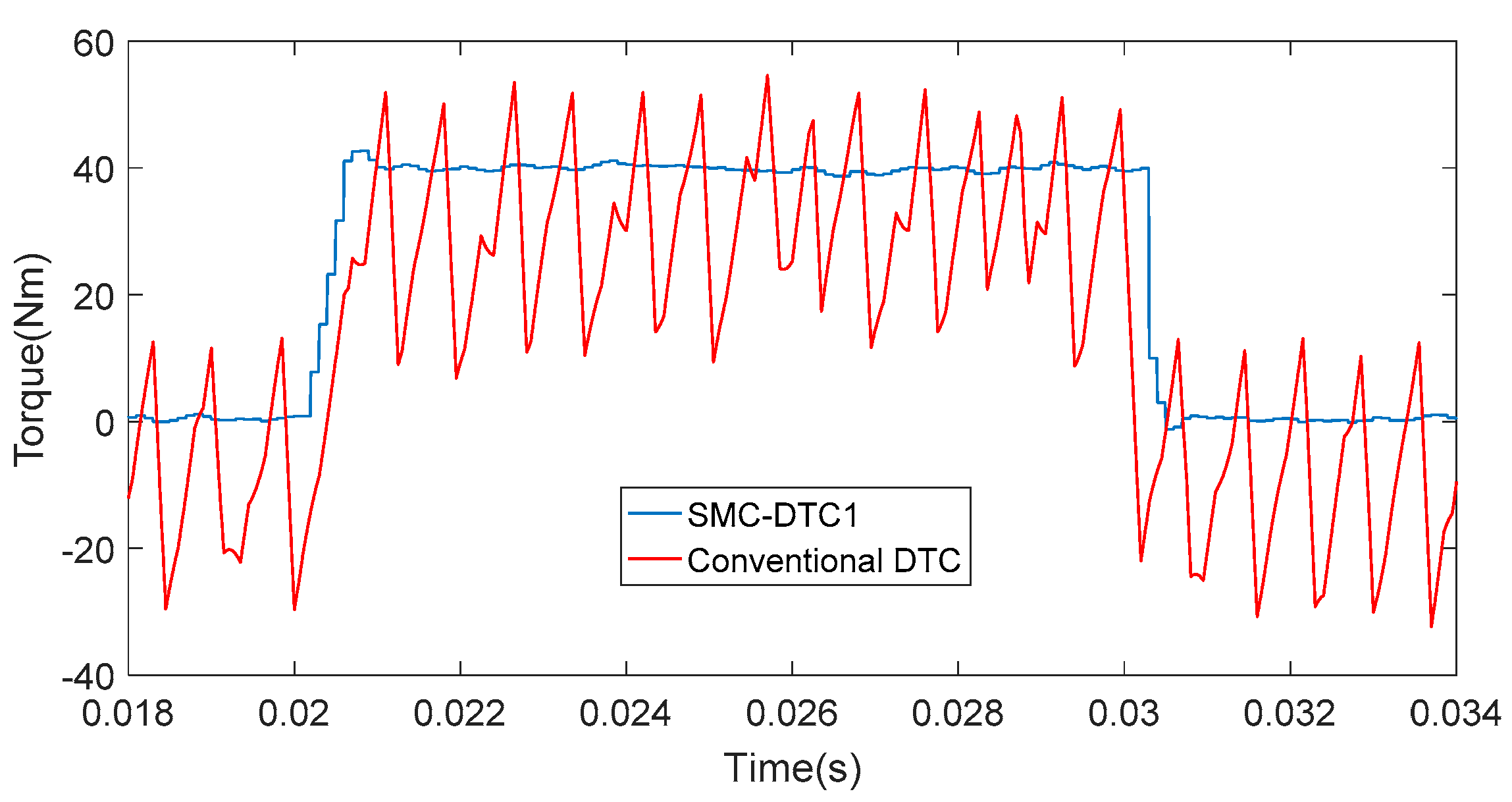
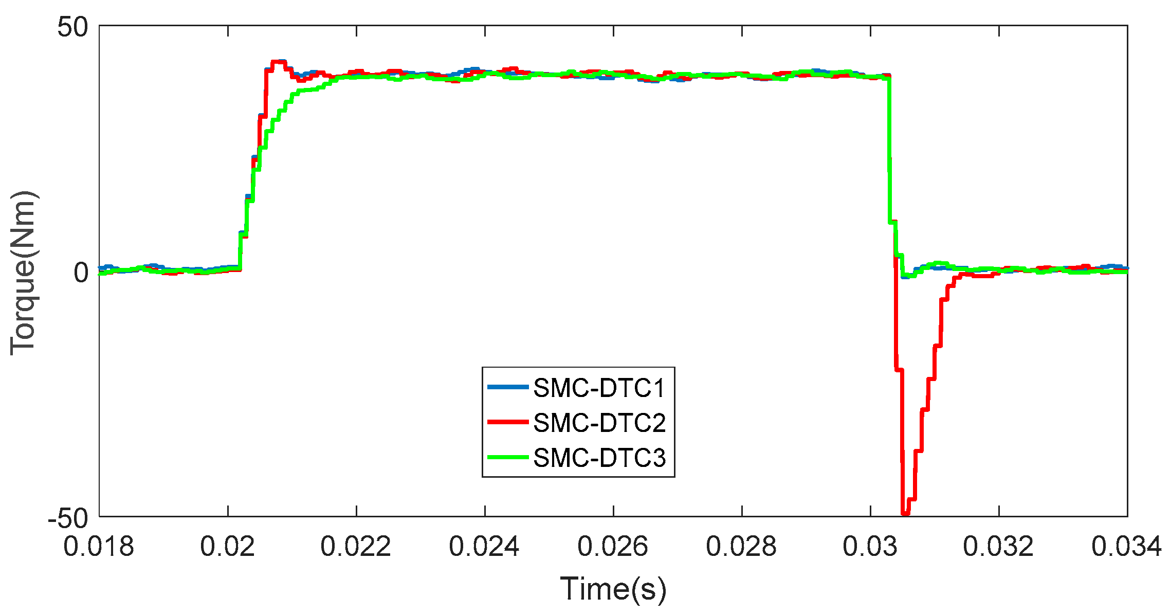
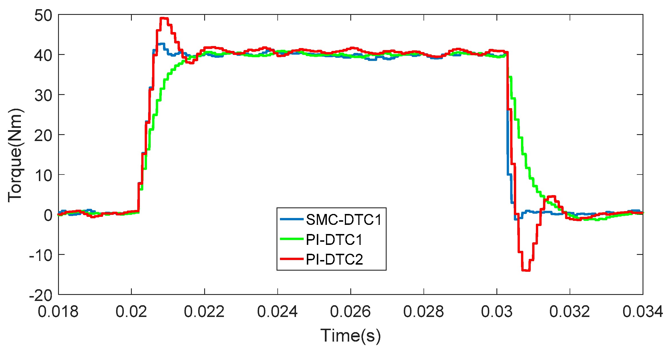
4.1. Torque Response in Transient-State Operation

For validating the dynamic response of torque control, rotor is set to be a constant speed of 1500 rpm, the torque command increased from 0 N·m to 40 N·m at the time of 20 ms and decreased to 0 N·m at the time of 30 ms.
The simulation results of asymmetric boundary layer SMC-DTC and conventional DTC method are presented in Figure 8. SMC-DTC1 is the result of asymmetric boundary layer one. It has a good performance on both the rising edge and the falling edge. The conventional DTC method has a sharp torque ripple and a steady error.
The simulation results of asymmetric boundary layer SMC-DTC and symmetric boundary layer SMC-DTC are presented in Figure 9. SMC-DTC1 is the result of asymmetric boundary layer one. SMC-DTC2 and SMC-DTC3 are the results of symmetric boundary layer SMC-DTC, | ϕ t + | = | ϕ t | . SMC-DTC2 is the result of narrow symmetric boundary layer one. It has a good performance on the rising edge, but there is a severe overshoot in the falling edge. SMC-DTC3 is the result of wide symmetric boundary layer one. It has a good performance on the falling edge, but the rising time is longer. Because of | ϕ t + | < | ϕ t | , the asymmetric boundary layer SMC-DTC has a good performance on both the rising edge and the falling edge.
The simulation results of asymmetric boundary layer SMC-DTC and PI-DTC are presented in Figure 10. PI-DTC1 and PI-DTC2 are the results of PI-DTC, but they used different parameters. PI-DTC1 has no overshoot but the rising time is longer. PI-DTC2 has a short rising time but the overshoot is bigger. Compared with PI-DTC, the asymmetric boundary layer SMC-DTC has shorter response time and less overshoot.
The response time and the statistical data between 20 ms and 30 ms are listed in Table 3. In this paper, torque ripples are computed according to the formula:
T r i p = 1 N i = 1 N ( T e ( i ) T e a v e ) 2 ,
where N is the number of samples, and T e a v e is the average values of the torque.
In contrast to the conventional DTC methods, the PI-DTC and SMC-DTC methods have smaller torque ripples and higher accuracy.

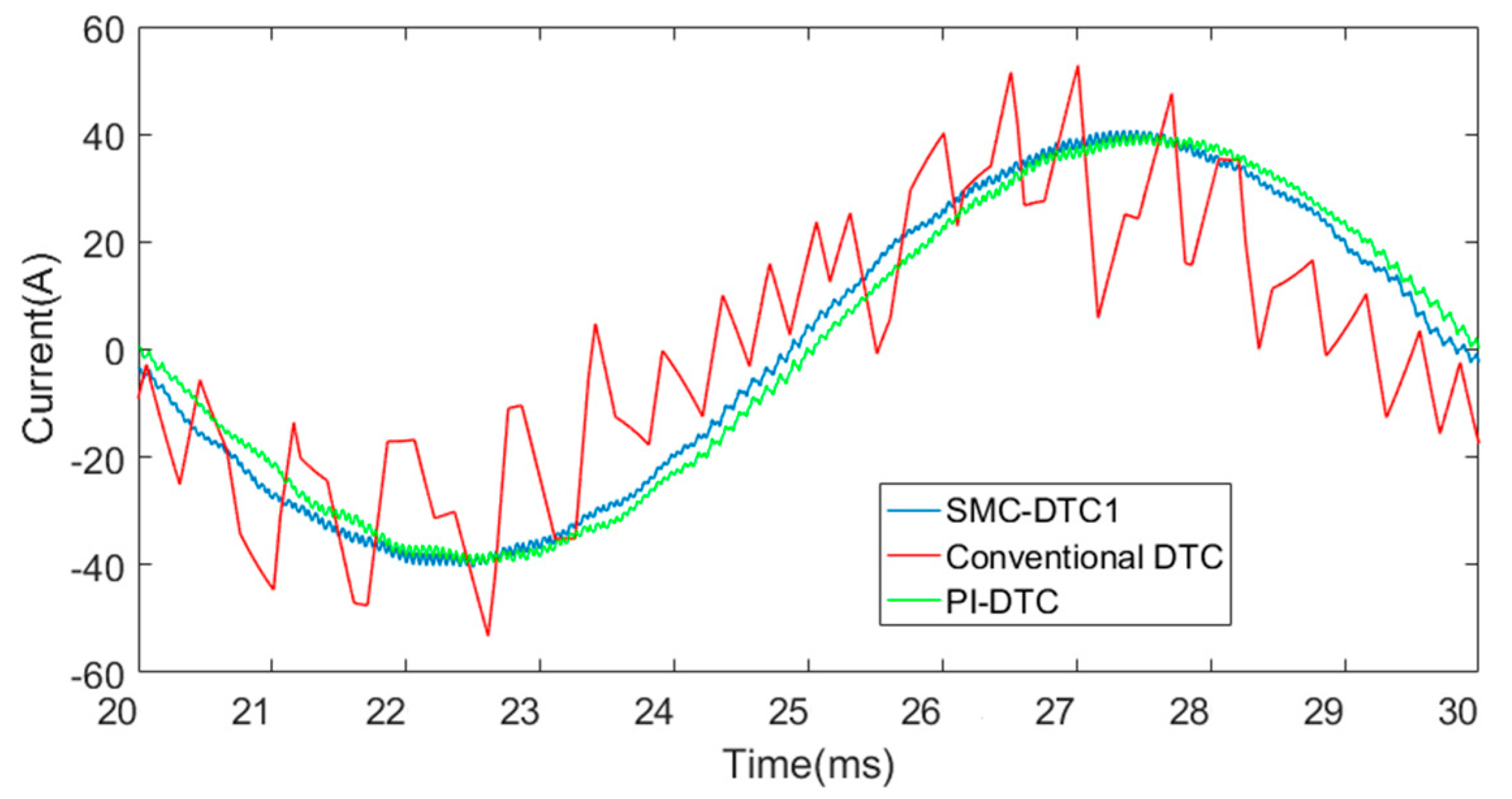
4.2. Stator Phase Current in Steady-State Operation
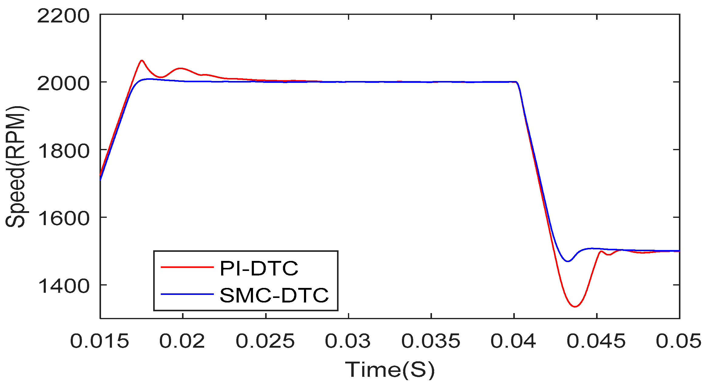
The waveform of the stator phase-A current for different control methods is shown in Figure 11. The total harmonic distortion (THD) of one cycle is 41.9%, 2.63%, and 2.84% with respect to the conventional DTC, PI-DTC and SMC-DTC. Therefore, the SVM technique in PI-DTC and SMC-DTC methods can effectively eliminate harmonic current.

4.3. Speed Response

To validate the performance of speed control, the speed command changed from 1000 rpm to 2000 rpm at the time of 10 ms and decreased to 1500 rpm at the time of 40 ms. The results are pictured in Figure 12.
In the rising stage, the speed overshoot is 64 rpm and 9 rpm with respect to the PI-DTC and SMC-DTC. In the falling stage, the speed overshoot is 165 rpm and 31 rpm respectively. The speed regulation under SMC method has a less overshoot and a higher control accuracy.

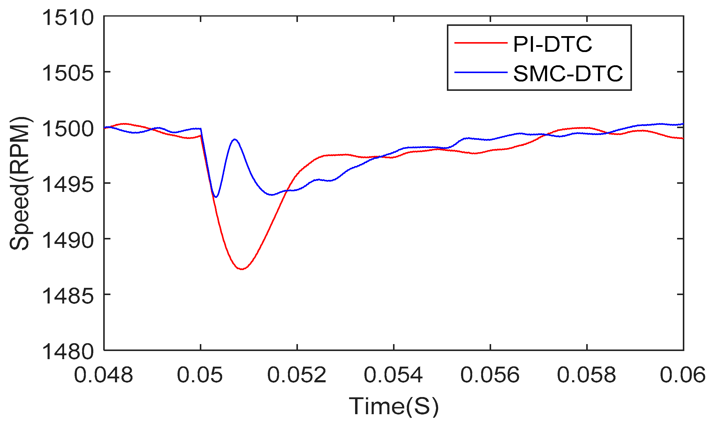
4.4. Robustness against the Load Disturbances

To validate the performance of speed control, the reference speed was maintained at 1500 rpm. The load torque is rising from 0 N·m to 10 N·m at the time of 50 ms. The emulated results of load disturbance rejection properties in two methods are presented in Figure 13. The speed drops are 13 rpm and 6 rpm with respect to the methods of PI-DTC and SMC-DTC. The speed regulation under SMC-DTC method reduce speed drop and enhances robustness against the load disturbances.

5. Conclusions

In the high-performance electric drive applications, fast and robust control of torque and speed are required. The traditional DTC method experiences high torque ripples and harmonic current. The PI controller in speed loop decreases the performance of dynamic response, and reduces the robustness of speed regulation. This paper has proposed a novel SMC-based DTC method, which regulates torque by adjusting the torque angle increment. The torque ripples and current distortion have been significantly suppressed by introducing the SVM technique. The overall DTC scheme eliminated the use of PI controller. The SMC-based torque controller and speed controller are both designed in order to achieve faster dynamic response, and enhance the robustness against torque disturbances and machine parameters’ variation. In addition, the torque controller is designed as asymmetric boundary layer SMC, which has a shorter response time and less overshoot than the symmetric boundary layer SMC. The simulation results have validated the effectiveness of the proposed DTC method.

Acknowledgments

This work was financially supported by National Key R&D Program of China (Grant No. 2016YFB0100605).

Author Contributions

Qiang Song put forward the conception of the control method, and designed the simulation. Yiting Li make the simulation, and drafting the article. Chao Jia established the simulation model.

Conflicts of Interest

No conflict of interest exits in the submission of this manuscript, and manuscript is approved by all authors for publication. I would like to declare on behalf of my co-authors that the work described was original research that has not been published previously, and not under consideration for publication elsewhere, in whole or in part. All the authors listed have approved the manuscript that is enclosed.

References

  1. Chan, C.C. The state of the art of electric, hybrid, and fuel cell vehicles. Proc. IEEE 2007, 95, 704–718. [Google Scholar] [CrossRef]
  2. Do, T.D.; Choi, H.H.; Jung, J.W. θ-D approximation technique for nonlinear optimal speed control design of surface-mounted PMSM drives. IEEE/ASME Trans. Mechatron. 2015, 20, 1822–1831. [Google Scholar] [CrossRef]
  3. Emadi, A.; Lee, Y.J.; Rajashekara, K. Power electronics and motor drives in electric, hybrid electric, and plug-in hybrid electric vehicles. IEEE Trans. Ind. Electron. 2008, 55, 2237–2245. [Google Scholar] [CrossRef]
  4. Zhang, Z.; Zhao, Y.; Qiao, W.; Qu, L. A discrete-time direct torque control for direct-drive PMSG-based wind energy conversion systems. IEEE Trans. Ind. Appl. 2015, 51, 3504–3514. [Google Scholar] [CrossRef]
  5. Martins, C.A.; Roboam, X.; Meynard, T.A.; Carvalho, A.S. Switching frequency imposition and ripple reduction in DTC drives by using a multilevel converter. IEEE Trans. Power Electron. 2002, 17, 286–297. [Google Scholar] [CrossRef]
  6. Xia, C.; Zhao, J.; Yan, Y.; Shi, T. A novel direct torque control of matrix converter-fed PMSM using duty cycle control for torque ripple reduction. IEEE Trans. Ind. Electron. 2014, 61, 2700–2713. [Google Scholar] [CrossRef]
  7. Kang, J.K.; Sul, S.K. New direct torque control of induction motor for minimum torque ripple and constant switching frequency. IEEE Trans. Ind. Appl. 1999, 35, 1076–1082. [Google Scholar]
  8. Pacas, M.; Weber, J. Predictive direct torque control for the PM synchronous machine. IEEE Trans. Ind. Electron. 2005, 52, 1350–1356. [Google Scholar] [CrossRef]
  9. Zhang, Y.; Zhu, J. A novel duty cycle control strategy to reduce both torque and stator flux ripples for DTC of permanent-magnet synchronous motor drives with switching frequency reduction. IEEE Trans. Power Electron. 2011, 26, 3055–3067. [Google Scholar] [CrossRef]
  10. Kenney, B.; Lorenz, R. Stator- and rotor-flux-based deadbeat direct torque control of induction machine. IEEE Trans. Ind. Appl. 2003, 39, 1093–1101. [Google Scholar] [CrossRef]
  11. Zhu, H.; Xiao, X.; Li, Y. Torque ripple reduction of the torque predictive control scheme for permanent-magnet synchronous motors. IEEE Trans. Ind. Electron. 2012, 59, 871–877. [Google Scholar] [CrossRef]
  12. Lai, Y.S.; Chen, J.H. A new approach to direct torque control of induction motor drives for constant inverter switching frequency and torque ripple reduction. IEEE Trans. Energy Convers. 2001, 16, 220–227. [Google Scholar]
  13. Yu, C.H.; Tseng, C.Y. Research on gear-change control technology for the clutchless automatic-manual transmission of an electric vehicle. Proc. Inst. Mech. Eng. Part D J. Automob. Eng. 2013, 227, 1446–1458. [Google Scholar] [CrossRef]
  14. Ren, Y.; Zhu, Z.Q.; Liu, J. Direct torque control of permanent-magnet synchronous machine drives with a simple duty ratio regulator. IEEE Trans. Ind. Electron. 2014, 61, 5249–5258. [Google Scholar] [CrossRef]
  15. Tang, L.; Zhong, L.; Rahman, M.F.; Hu, Y. A novel direct torque controlled interior permanent magnet synchronous machine drive with low ripple in flux and torque and fixed switching frequency. IEEE Trans. Power Electron. 2004, 19, 346–354. [Google Scholar] [CrossRef]
  16. Swierczynski, D.; kazmierkowski, M. Direct torque control of permanent magnet synchronous motor (PMSM) using space vector modulation (DTC-SVM)—Simulation and experimental results. In Proceedings of the 28th Annual Conference of the IEEE Industrial Electronics Society, Sevilla, Spain, 5–8 November 2002; Volume 1, pp. 751–755. [Google Scholar]
Figure 1. Two-level, three-phase voltage source converter for permanent magnet synchronous motor (PMSM).
Energies 11 00657 g001
Figure 2. Eight voltage space vectors in α-β stationary reference frame.
Energies 11 00657 g002
Figure 3. Control of the amplitude of stator flux linkage.
Energies 11 00657 g003
Figure 4. Effects of voltage vector on the stator flux and torque.
Energies 11 00657 g004
Figure 5. Block diagram of the classical direct torque control (DTC) method for PMSM.
Energies 11 00657 g005
Figure 6. The relationship between stator flux linkage and voltage vector.
Energies 11 00657 g006
Figure 7. Control diagram of proposed DTC method for PMSM.
Energies 11 00657 g007
Figure 8. Torque response of sliding-mode-control (SMC)-DTC and conventional DTC.
Energies 11 00657 g008
Figure 9. Torque response of asymmetric and symmetric boundary layer SMC-DTC.
Energies 11 00657 g009
Figure 10. Torque response of asymmetric boundary layer SMC-DTC and proportional-integral (PI)-DTC.
Energies 11 00657 g010
Figure 11. Waveform of the stator phase-A current.
Energies 11 00657 g011
Figure 12. Performance of speed response.
Energies 11 00657 g012
Figure 13. Speed drop under the load disturbance.
Energies 11 00657 g013
Table 1. Six-vector switching table for converter.
θ 1 θ 2 θ 3 θ 4 θ 5 θ 6
V 2 ( 110 ) V 3 ( 010 ) V 4 ( 011 ) V 5 ( 001 ) V 6 ( 101 ) V 1 ( 100 )
V 6 ( 101 ) V 1 ( 100 ) V 2 ( 110 ) V 3 ( 010 ) V 4 ( 011 ) V 5 ( 001 )
V 3 ( 010 ) V 4 ( 011 ) V 5 ( 001 ) V 6 ( 101 ) V 1 ( 100 ) V 2 ( 110 )
V 5 ( 001 ) V 6 ( 101 ) V 1 ( 100 ) V 2 ( 110 ) V 3 ( 010 ) V 4 ( 011 )
Table 2. Parameters of PMSM.
ParameterValueUnit
Voltage supply300V
Rated speed2000rpm
Rated torque40N·m
Rated current (RMS)28A
Flux linkage0.1821Wb
Number of pole pairs4-
Stator resistance0.129Ω
q-axis inductance0.00153H
d-axis inductance0.00153H
Inertia moment0.001kg·m2
Viscous friction coefficient0.0019N·m·s/rad
Table 3. Torque response.
Result-Conventional DTCSMC-DTC1SMC-DTC2SMC-DTC3PI-DTC1PI-DTC2Unit
Rising time0.950.580.61.71.70.6ms
Falling time0.130.460.40.51.90.5ms
T e a v e 31.939.939.93.984040N·m
T r i p 11.550.580.50.460.390.38N·m

