Article

A Decentralized, Hybrid Photovoltaic-Solid Oxide Fuel Cell System for Application to a Commercial Building

by
Alexandros Arsalis
1,2,* and
George E. Georghiou
1,3
1
FOSS Research Centre for Sustainable Energy, University of Cyprus, Nicosia 1678, Cyprus
2
Department of Mechanical and Manufacturing Engineering, University of Cyprus, Nicosia 1678, Cyprus
3
Department of Electrical and Computer Engineering, University of Cyprus, Nicosia 1678, Cyprus
*
Author to whom correspondence should be addressed.
Energies 2018, 11(12), 3512; https://doi.org/10.3390/en11123512
Submission received: 5 November 2018 / Revised: 30 November 2018 / Accepted: 11 December 2018 / Published: 16 December 2018

Abstract

:
New energy solutions are needed to decrease the currently high electricity costs from conventional electricity-only central power plants in Cyprus. A promising solution is a decentralized, hybrid photovoltaic-solid oxide fuel cell (PV-SOFC) system. In this study a decentralized, hybrid PV-SOFC system is investigated as a solution for useful energy supply to a commercial building (small hotel). An actual load profile and solar/weather data are fed to the system model to determine the thermoeconomic characteristics of the proposed system. The maximum power outputs for the PV and SOFC subsystems are 70 and 152 kWe, respectively. The average net electrical and total efficiencies for the SOFC subsystem are 0.303 and 0.700, respectively. Maximum net electrical and total efficiencies reach up to 0.375 and 0.756, respectively. The lifecycle cost for the system is 1.24 million USD, with a unit cost of electricity at 0.1057 USD/kWh. In comparison to the conventional case, the unit cost of electricity is about 50% lower, while the reduction in CO2 emissions is about 36%. The proposed system is capable of power and heat generation at a lower cost, owing to the recent progress in both PV and fuel cell technologies, namely longer lifetime and lower specific cost.

1. Introduction

Efforts to increase energy efficiency have intensified over recent years due to the rapid increase of fossil fuel prices and also the need to decrease harmful emissions to the atmosphere [1]. Cogeneration allows the combination of various technologies to improve the fuel efficiency of electricity-only power plants or combined-heat-and-power (CHP) systems [2]. Earlier systems have included combined cycle power plants at large scale (10–100 MWe). In the resulting systems there exists a high level of complexity due to the increased number of parameters. Therefore, there is a need to apply advanced methodologies able to determine optimum solutions. However, this procedure becomes rigorous in case a number of parameters (e.g., thermodynamic, economic and environmental criteria) must be included [3]. Fuel cell technology has been proposed at the kW to the MW scale in a number of proposed systems. In lower temperature proton exchange membrane fuel cells (PEMFCs), CHP systems have been primarily applied at the kW scale, for smaller residential applications, where low-grade heat (recovered from the fuel cell exhaust) is usually adequate to cover residential load profiles, such as space heating and domestic hot water preparation [4,5]. These systems are sometimes operated jointly with vapor compression heat pumps to boost heat generation and/or to provide space cooling [6]. Such systems have been proposed for single-family households and in some cases for multi-unit residential applications [7,8]. Coupling of SOFCs with absorption chiller-heater units has also been proposed for larger scale, decentralized applications such as commercial buildings [9]. Although the resulting operational configurations have led to high system efficiencies (80% to 90%), their complexity resulted in high capital cost, which often dominates lifecycle cost.
Recent progress in SOFC technology includes important advances, such as higher lifetime, lower capital cost, higher electrical efficiency and simpler fuel processing requirements (in the case of natural gas-fueled systems—as compared to PEMFC technology) [10,11]. For small-scale residential applications, SOFC-based, natural gas-fueled micro-CHP systems have been proposed through thermoeconomic modeling and optimization techniques and improved operational strategies [12,13]. The application of effective optimization techniques, such as decomposition strategies, have been applied in some cases for the design/synthesis optimization of such systems [7,8]. For large-scale applications, the possibility of combining SOFC technology with heat engines, such as gas turbine cycles, has been thoroughly investigated since the early 2000s. In natural gas-fueled hybrid systems, where high temperature SOFC stacks have been integrated with gas turbine cycles, effort was placed on the increase of system efficiency to lower fuel consumption [14]. Due to the complexity of the proposed systems, the design/synthesis options are usually evaluated with advanced optimization techniques [15,16].
More recent research effort has focused on the possibility of combining fuel cell technology with renewable energy sources (RES). The combination of RES with fuel cell technology is a more environmentally friendly solution than decentralized hybrid photovoltaic (PV)-gas turbine systems, because in the latter case emissions are generated on-site, i.e., near the serviced buildings [17,18]. The deployment of PV units continues to increase because of significant cost reductions in addition to supportive policies, such as net-metering [19]. In such systems, excess generation of electricity from RES, e.g., via solar PV panels or wind turbines, can be converted to hydrogen through an electrolyzer unit [20], stored in a hydrogen storage tank, and then reconverted to electricity when renewable energy is unavailable [21]. The design of such systems for variable load has proven difficult and in most cases the proposed systems have considered grid-connected operation to allow import/export of electricity, while in other cases a constant load operation was followed [22,23]. A combination of RES with natural gas (or biogas)-fueled fuel cell units could allow a rapid deployment of these hybrid systems [24]. Currently the application of hybrid PV-SOFC systems seems more attractive for commercial buildings as the load demand closely matches the solar energy availability. The use of dynamic or quasi-steady state modeling is usually required to model the system as realistically as possible [25,26].
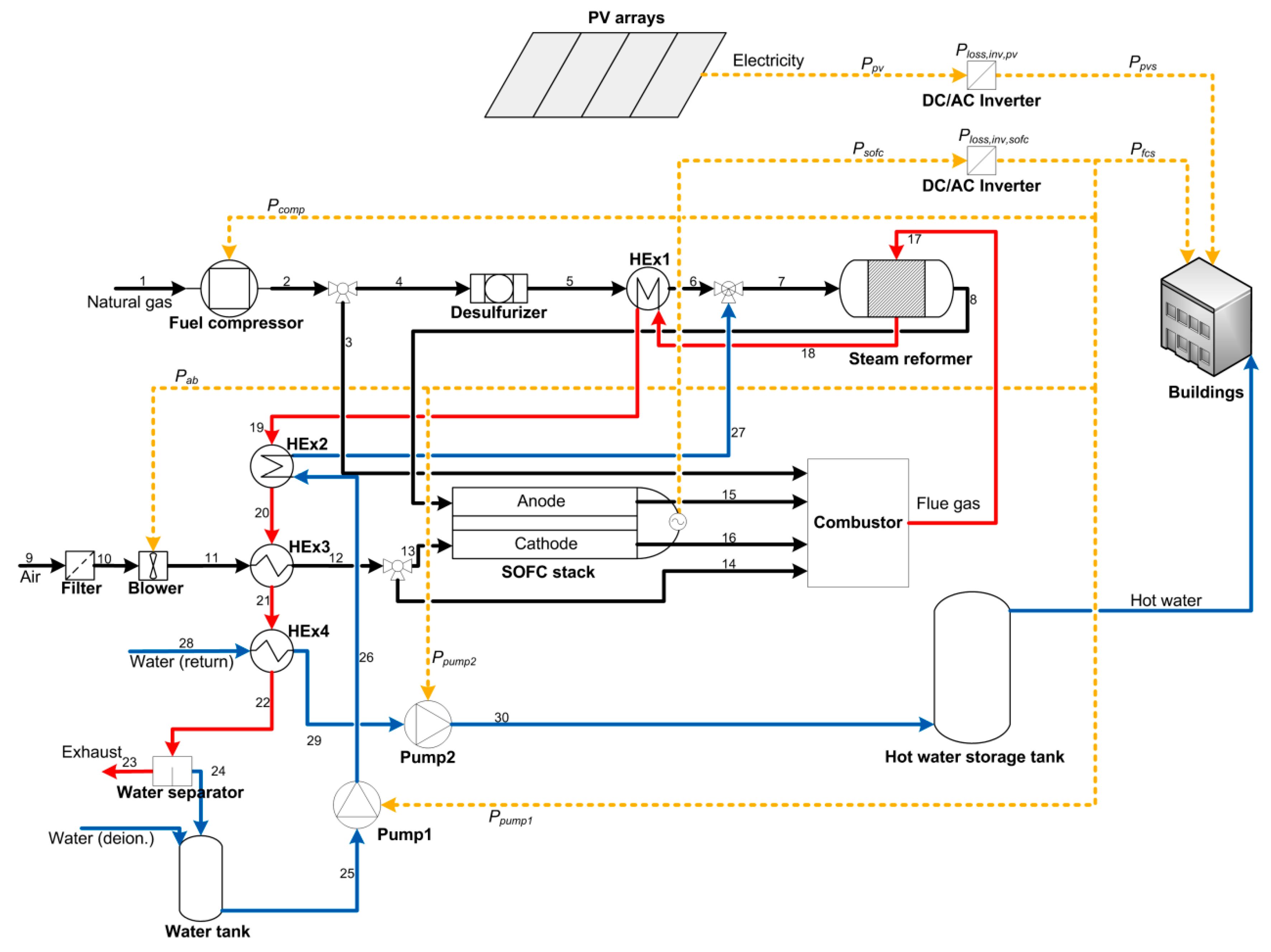
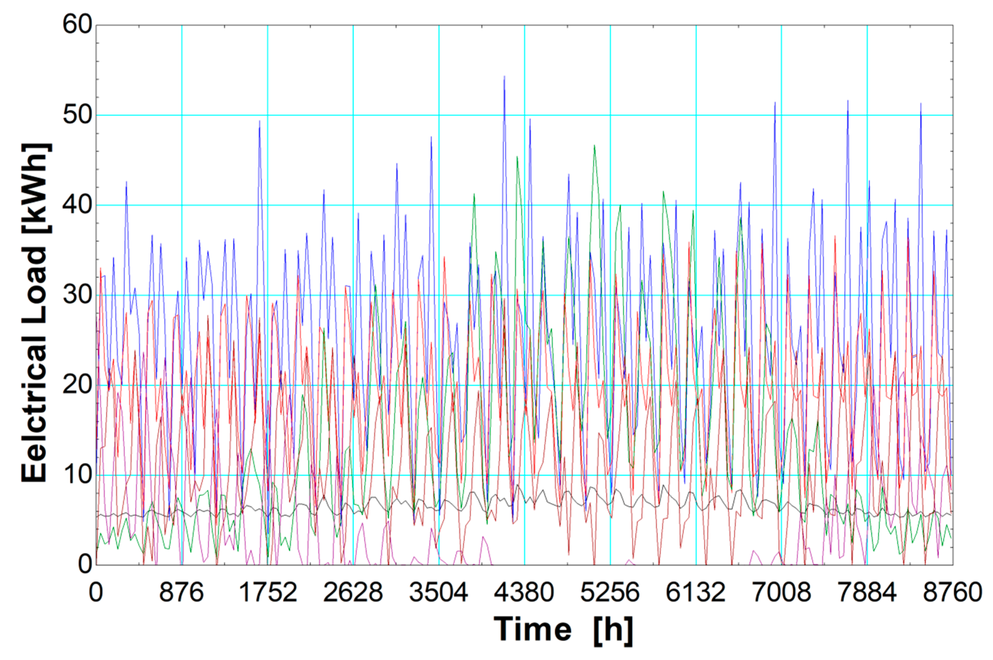
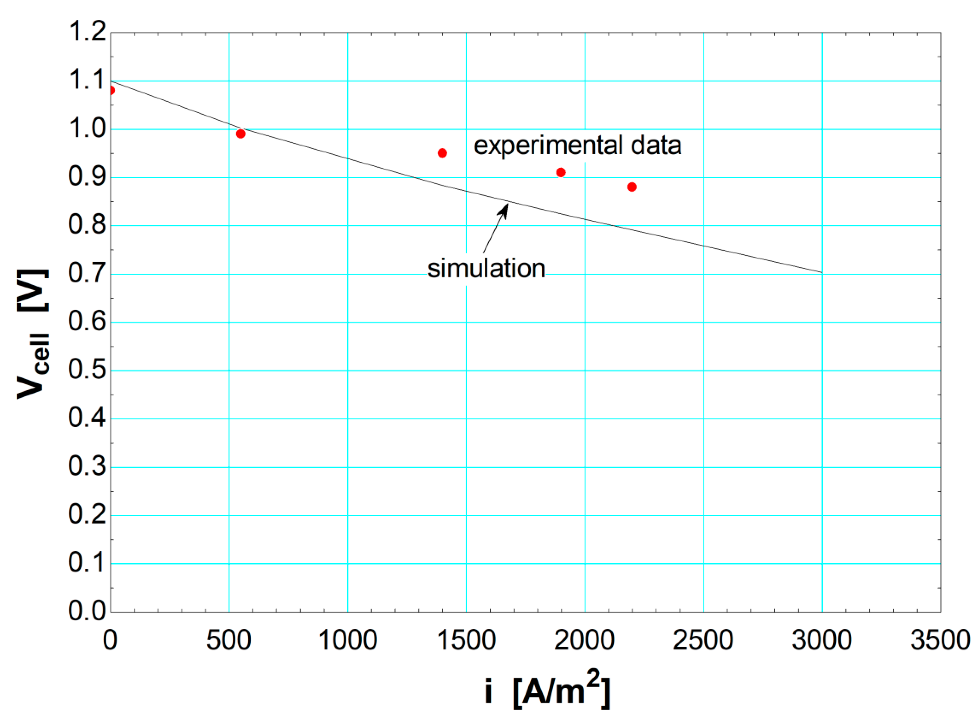
The objective of this research study is the thermoeconomic modeling of a decentralized, hybrid PV-SOFC system for application to a commercial building. The PV subsystem, the fuel cell stack, and the steam methane reformer (SMR) reactor components are modeled in detail to allow a realistic representation of their operation at both design and off-design conditions. In addition, a significant shortcoming of previous studies on hybrid RES-fuel cell systems is the fact that, in most cases, actual load profiles have not been considered. The omission of an actual load profile prohibits the extraction of realistic outcomes on the actual viability of such systems. The current study considers both solar/weather data and an actual load profile for a commercial building for the whole year. This approach leads to a more accurate determination of the thermoeconomic characteristics of the proposed system, allowing a direct comparison to conventional useful energy generation. The fuel processor (pre-reformer) is of the SMR type, since it is more efficient than other technologies (e.g., partial oxidation), allowing more efficient natural gas conversion to hydrogen [
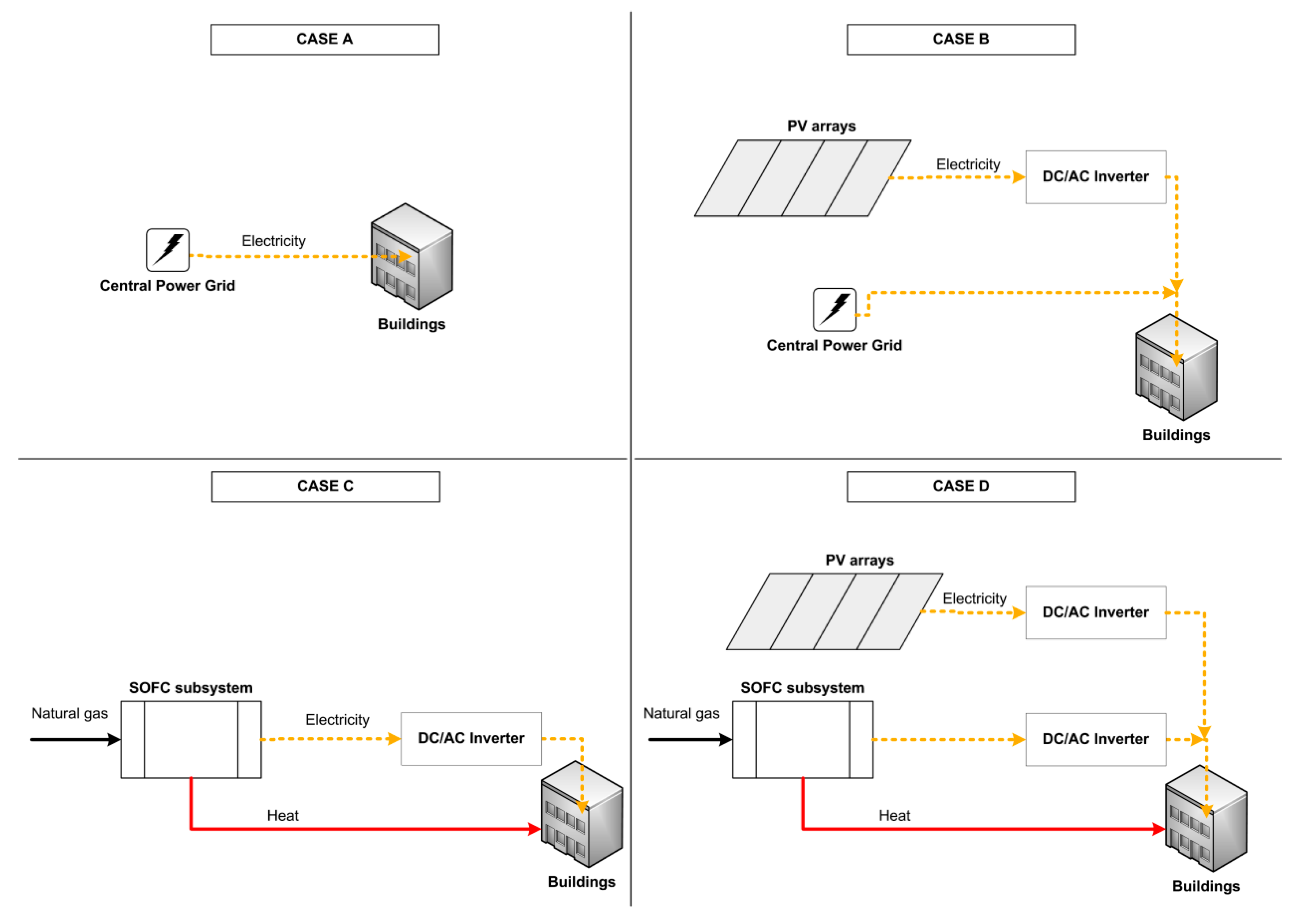
11]. The current research study investigates the economic competitiveness of the proposed system in comparison to conventional or alternative power generation. Four different cases are investigated and compared, namely: (A) Central power grid connection (conventional), (B) central power grid connection assisted with PV arrays, (C) non-grid connected SOFC system and (D) decentralized hybrid PV-SOFC system (proposed system). The outcomes of the research work are expected to reveal the possibility of combining and utilizing two highly advantageous technologies, i.e., PVs and solid oxide fuel cells, with an analysis beyond theoretical predictions. This is done with a detailed thermoeconomic modeling of the components, and further on with their overall integration in the system model. Moreover, through the development of a cost model, a complete thermoeconomic analysis is facilitated to lay out the characteristics of the proposed hybrid system.

2. System Configuration

The proposed system, shown in Figure 1, was designed to fully fulfill an actual load profile for a commercial building. It includes a natural gas-fueled SOFC subsystem and a solar PV subsystem. The system also includes DC/AC inverters to convert the DC current generated by the PV and the SOFC subsystems to AC electricity prior to distribution to the buildings. In the SOFC subsystem, natural gas (NG) is compressed in the fuel compressor and sulfur is removed with the desulfurizer. The NG is preheated through heat exchanger (HEx) HEx1 before entering the SMR. The endothermic process in the SMR requires external heating, which is generated by a catalytic combustor. The synthesis gas (syngas) at the SMR exit is fed to the fuel cell anode. Air drawn from the atmosphere is filtered and blown to HEx3 for preheating and then fed to the fuel cell cathode. The fuel cell reaction in the SOFC stack generates electricity and also a hot mixture at the fuel cell exit. The hot exhaust mixture is fed to the combustor, along with natural gas from the natural gas supply and air. The flue gas exiting the SMR is used to provide heat for the four heat exchangers (HEx1–HEx4). HEx2 is used to generate steam for the SMR. HEx4 is used to provide low-grade heat externally, i.e., to heat water from recovered heat and supply it to the hot water storage tank. Through the hot water storage tank, hot water is provided to the buildings. At the exit of HEx4, the exhaust flue gas is released to the atmosphere after separation of water through a water separator.
The main assumptions for the current study are the following:
  • The proposed system operates in complete autonomy, i.e., it is not connected to a central power grid (no import/export of electricity).
  • The maximum PV power output is set equal to the minimum electric load in the load profile to ensure no power is wasted. In turn, this value is used to size the SOFC subsystem. The system model is modeled in such a way to ensure that the proposed system is capable of completely covering the building load profile at all times, throughout the year.
  • Heat losses are considered in the three main components of the SOFC subsystem, namely: The SMR reactor, the SOFC stack, and the catalytic combustor. Additionally, pressure losses are considered in every component of the SOFC subsystem.
  • Additional heating (space heating and domestic hot water) is provided through natural gas-fired boilers, while space cooling is provided through electric vapor-compression heat pumps. This equipment is already available in the buildings and therefore its associated capital cost is not considered in the thermoeconomic modeling for this study.
  • The hourly solar and ambient temperature data used in the simulation of the PV subsystem are based on a Typical Meteorological Year—TMY2 for Nicosia, Cyprus [27].
  • The consumption data system is applied for a small hotel with load profile data extracted from [28]. The load profile includes the following loads (all in an electrical energy basis): Fans, interior equipment, interior lights, space cooling, space heating, and domestic hot water. The load profile is shown in Figure 2.

3. System Modeling

The modeling of the components of the proposed hybrid system was based on first principles to accurately represent the coupling and operation of the system as realistically as possible. After modeling each component, the components were coupled together to form the SOFC subsystem. Subsequently, simulation of the PV subsystem generates PV data for the simulation of the overall system model. Additionally, a cost model was developed for the economic analysis of the proposed system. It includes all necessary cost functions and inputs needed for the calculation of capital costs, fuel cost, lifecycle cost and unit cost of electricity. The modeling of the system was developed with the software Engineering Equation Solver (EES)—Professional version. Hourly simulation data were generated for a complete year, i.e., 8760 hourly segments.

3.1. Photovoltaic Subsystem

The PV subsystem was based on the Hay-Davies-Klucher-Reindl (HDKR) modeling methodology [29], i.e., the total incident solar radiation on a tilted surface is calculated with a consideration of both the ground-reflected and the beam effects:
I T = ( I b + I d A i ) R b + I d ( 1 A i ) ( 1 + cos β 2 ) [ 1 + f sin 3 ( β 2 ) ] + I ρ g ( 1 cos β 2 ) .
In the PV array, the temperature was calculated with the relation (the effect of wind speed is considered negligible):
T c T a m b T N O C T T a m b , N O C T = I T I T , r e f e r ( 1 η r e f 0.9 ) .
The array’s maximum power point efficiency is:
η m p = η r e f e r ( 1 + μ m p ( T c T a m b , N O C T ) ) .
The PV array’s electricity output is:
P p v = A p v , a r r a y I T η m p .

3.2. SOFC Subsystem

The SOFC subsystem includes the fuel processing subsystem with the fuel pre-reformer (SMR reactor), four heat exchangers, SOFC stack and actuators. For the configuration shown in Figure 1, the inputs are given in Table 1. The fuel utilization factor was set at 0.92, and fuel cell temperature was set at 750 °C [10]. The temperature of fuel at the fuel preheater exit, the temperature of the reformate at the SMR reactor exit/anode inlet, and the temperature of the flue gas exiting the catalytic combustor were set at 450, 650 and 1005 °C, respectively [11]. HEx4 flue gas exit temperature was set at 55 °C because it must be at 25 °C above the dew point of the combustion product gases [10]. The steam-to-carbon ratio was set at 2.5, which although it is a relatively low value, the SOFC can treat CO as fuel [30], and therefore CO content does not need to be significantly reduced prior to anode inlet.

3.2.1. SMR Reactor

An SMR reactor configuration was assumed for the pre-reformer. The SMR reactor model is based on chemical equilibrium [10,11,12]. Two chemical reactions were included: SMR reaction (methane-steam), and water gas shift (WGS) reaction (carbon monoxide-steam) [31]. Since the SMR reaction is endothermic, heat must be supplied by an external source [32] (in this case from the catalytic combustor).
For the SMR reaction, i.e., CH 4 + H 2 O CO 2 + 3 H 2 , the overall change in Gibbs free energy is:
Δ G s m r = 1 g CH 4 1 g H 2 O + 1 g CO + 3 g H 2 ,
arg 1 = ( Δ G s m r R T r e f , o u t ) .
The equilibrium constant at the given temperature for the SMR reaction is:
K s m r = exp ( arg 1 ) .
For the WGS reaction, CO + H 2 O CO 2 + H 2 , the overall change in Gibbs free energy is:
Δ G w g s = 1 g CO 1 g H 2 O + 1 g CO 2 + 1 g H 2 ,
arg 2 = ( Δ G w g s R T r e f , o u t ) .
The equilibrium constant at the given temperature for the WGS reaction is:
K w g s = exp ( arg 2 ) .
The molar flow output is defined as:
n ˙ r e f , o u t = n ˙ r e f , i n , CH 4 + n ˙ r e f , i n , H 2 O + 2 X s m r .
The equilibrium constants for the aforementioned reactions are [33]:
K s m r y r e f , o u t , CH 4 y r e f , o u t , H 2 O = y r e f , o u t , CO y r e f , o u t , H 2 3 ( p r e f , o u t p a m b ) 2 ,
K w g s y r e f , o u t , CO y r e f , o u t , H 2 O = y r e f , o u t , CO 2 y r e f , o u t , H 2 .
A molar flow rate balance for each species can be applied at the reformer inlet and outlet:
n ˙ r e f , o u t , CH 4 = n ˙ r e f , i n , CH 4 X s m r .
n ˙ r e f , o u t , H 2 O = n ˙ r e f , i n , H 2 O X s m r X w g s .
n ˙ r e f , o u t , CO = X s m r X w g s .
n ˙ r e f , o u t , H 2 = 3 X s m r + X w g s .
n ˙ r e f , o u t , CO 2 = X w g s .
The flue gas temperature at exit is calculated through an energy balance in the reformer:
Q ˙ h e a t , s m r + E ˙ i n , s m r = E ˙ o u t , s m r + Q ˙ l o s s , s m r .

3.2.2. SOFC Stack

The SOFC stack model includes both the fuel cell reaction and direct internal reforming processes. For the latter, the reforming process takes place at the surface of the catalysts (anode), where hydrogen gas is mixed with steam before entering the anode [34]. Internal reforming is identical to the SMR reactor modeling equations, described in Section 3.2.1.
For the fuel cell reaction, the open circuit voltage is modeled as follows [10,11,12]:
E o c v = E o c v , 0 + R T f c 2 F ln ( y a n o , H 2 p f c p a m b y c a t , O 2 p f c p a m b y a n o , H 2 O p f c p a m b ) .
The reversible voltage is:
E o c v , 0 = Δ g o f 2 F .
The Gibbs free energy is:
Δ g o f = 1 g H 2 O 0.5 g O 2 1 g H 2 .
The activation losses are based on the Butler–Volmer equation, defined for the anode and cathode, respectively, to determine the current density:
i = i 0 , a n o ( exp ( α n e F R T f c V a c t , a n o ) exp ( ( 1 α ) n e F R T f c V a c t , a n o ) ) ,
i = i 0 , c a t ( exp ( α n e F R T f c V a c t , c a t ) exp ( ( 1 α ) n e F R T f c V a c t , c a t ) ) ,
where i 0 , a n o and i 0 , c a t are the exchange current densities for the anode and cathode, respectively:
i 0 , a n o = γ a n o ( y a n o , H 2 p f c p a m b ) ( y a n o , H 2 O p f c p a m b ) 0.5 exp ( E a c t , a n o R T f c ) ,
i 0 , c a t = γ c a t ( y c a t , O 2 p f c p a m b ) 0.25 exp ( E a c t , c a t R T f c ) .
The activation overvoltage is determined as the sum of anode and cathode losses:
V a c t = V a c t , a n o + V a c t , c a t .
Concentration losses are the gradual losses due to the reactant depletion in the catalyst layer, and they are defined as the difference between the Nernst potential at the catalyst layer and the bulk flow at both anode and cathode [35]. The limiting current densities for hydrogen and oxygen species are defined as follows, respectively:
i L , H 2 = 2 F C H 2 , 0 h m , H 2 ,
i L , O 2 = 4 F C O 2 , 0 h m , O 2 ,
where C H 2 , 0 and C O 2 , 0 are the concentration of species for hydrogen and oxygen, respectively.
The concentration losses are [35]:
V c o n c = R T f c 2 F l n ( ( 1 i i L , H 2 ) ( 1 i i L , O 2 ) 0.5 ) .
The Ohmic losses are defined as the product of current density and Ohmic resistance:
V o h m = i R i .
Based on the above definitions, the cell voltage can be defined as follows [34]:
V c e l l = E o c v V a c t V c o n c V o h m .
Fuel cell stack voltage, current, and power are defined as follows, respectively:
V f c = V c e l l n c e l l s ,
I f c = i A f c ,
P ˙ s o f c = V f c I f c .
The molar flow rate of oxygen at the inlet of the cathode can be calculated through an energy balance:
Q ˙ i n , f c = Q ˙ o u t , f c + Q ˙ l o s s , f c + P ˙ s o f c

3.2.3. Auxiliary Components

The auxiliary components are the actuators (air blower, fuel compressors and two water pumps), the catalytic combustor and the four heat exchangers. The actuators were modeled using fundamental equations, while the catalytic combustor model was based on an energy balance of products and reactants. The modeling of the heat exchangers was based on the Logarithmic Mean Temperature Difference (LMTD) method.

3.3. Overall System

The proposed hybrid system includes two prime movers for the generation of electrical energy. Additionally, in the case of the SOFC subsystem, heat is generated and recovered for external use in the buildings to satisfy the heating loads. Therefore, an algorithm must be included in the code of the system model to relate fuel cell power output, PV power output and power demand. Additionally, since the system is non-grid connected, it must be ensured that no excess power is generated from the PV subsystem.
If ( P l o a d > P p v s ) then P f c s = P l o a d P p v s P p v , e x c = 0 Else If ( P l o a d < P p v s ) then    P f c s = 0    P p v , e x c = P p v s P l o a d    Else    P f c s = 0    P p v , e x c = 0 EndIf EndIf
The inverter power losses for the PV subsystem are calculated as follows:
P ˙ l o s s , i n v , p v = P ˙ p v ( 1 η i n v , p v ) ,
P ˙ p v s = P ˙ p v P ˙ l o s s , i n v , p v .
Similarly, for the SOFC subsystem:
P ˙ l o s s , i n v , s o f c = P ˙ s o f c ( 1 η i n v , s o f c ) .
The net electrical power output for the SOFC subsystem is defined as follows:
P ˙ f c s = P ˙ s o f c P ˙ l o s s , i n v , s o f c P ˙ a b P ˙ c o m p P ˙ p u m p 1 P ˙ p u m p 2 .
The net electrical efficiency for the SOFC subsystem can be based on the lower heating value (LHV) or the higher heating value (HHV), respectively [36]:
η e l , n e t , L H V = P ˙ f c s E ˙ f u e l , L H V ,
η e l , n e t , H H V = P ˙ f c s E ˙ f u e l , H H V .
The thermal efficiency is the ratio of recovered heat rate actually used to cover the building heating loads (fully or partly) to the chemical energy rate of the fuel consumed by the SOFC subsystem:
η t h = Q ˙ t h E ˙ f u e l , L H V
The total SOFC subsystem efficiency is the sum of SOFC subsystem net electrical efficiency and thermal efficiency:
η f c s = η e l , n e t , L H V + η t h .
The thermal-to-electric ratio is the ratio of recovered heat rate to net electrical power output:
T E R = Q ˙ t h P ˙ f c s .
When the recovered heat from the SOFC subsystem is inadequate to cover the heating loads, additional heat must be generated externally:
P h e a t , n e t = max ( 0 , ( P h e a t + P d h w ) P t h ) .
The total load profile electrical energy requirement is the sum of electricity required to operate the fans, the interior lights, the interior equipment, the space cooling, and supplementary heating:
P l o a d = P f a n + P l i g h t + P e q u i p + P c o o l + P h e a t , n e t .

3.4. Cost Model

A cost model was developed to determine the economic performance of the proposed hybrid system, based on the methodology found in [37]. The modeling equations are shown in Table 2, while the values of the constant parameters are given in Table 3. The specific cost of the PV array was set at 2.00 USD/W, which is based on approximate values given in [38]. The specific cost of the SOFC subsystem and the power subsystem were approximated from values given in [39], and they were set at 2.00 and 1.00 USD/W, respectively. The specific cost of the power subsystem included the two DC/AC inverters and the power conditioning components. The cost of fuel (i.e., natural gas) was set at 7.19 USD/MMBTU, which is the current cost in the European Union (EU) [40]. The lifetime was set at 20 years for the system (i.e., PV arrays and power subsystem) [19,37] and 5 years for the SOFC subsystem [39], with a fuel cell operation factor set at 0.50, since the fuel cell is operated for approximately 50% of the time. The cost of the hot water storage tank was based on an approximation from values given in [41]. The values for the remaining parameters were taken from [37].

4. Results and Discussion

In this section the system model is validated with available literature data. Then, the performance of the proposed hybrid system is presented in detail. Finally, the proposed hybrid system is compared with conventional and alternative system configurations to analyze and investigate its competitiveness in regard to key thermoeconomic parameters.

4.1. Validation

For the validation of the SOFC stack, relevant literature data from [42] were used. As shown in Figure 3, the literature data compare well against the simulation data generated by the system model, with only a small deviation in the results. The PV subsystem was validated in a previous publication by some of the authors [43].

4.2. Performance Characteristics of the Proposed Hybrid System

The proposed hybrid PV-SOFC system was sized in accordance with the requirements of the assumptions defined in Section 2. Based on these assumptions, the PV maximum power output is 70 kWe, while the SOFC maximum power output at full-load (i.e., design conditions) is 152 kWe. The average annual net electrical efficiency of the SOFC subsystem is 0.303, while total efficiency is 0.700. Maximum net electrical and total efficiencies can reach up to 0.375 and 0.756, respectively. In terms of annual useful energy generation, the electricity output (actual electricity delivered to the buildings) of the PV and SOFC subsystems is 135.9 and 451.2 MWh, respectively. The SOFC subsystem also provides 694.5 MWh of heating through heat recovery of the flue gas exhaust by the SOFC subsystem. This amount can almost completely cover the heating needs of the buildings, with only 7.2 MWh needed to be generated in addition. The current density at design conditions is 1228 A/m2. A summary of the performance characteristics of the proposed system is given in Table 4. For an illustration of the performance of the system, Table 5 includes the values for the thermophysical parameters of the system at full load conditions for the SOFC subsystem.

4.3. Thermoeconomic Analysis of the Proposed Hybrid System

4.3.1. System Cost Analysis

A cost analysis of the proposed hybrid system is given in Table 6. In terms of capital cost, the highest cost is allocated for the purchase of the SOFC subsystem at 607,540 USD, while the cost for the PV arrays is 140,132 USD. The cost of the power subsystem is also significant at 221,951 USD, which means that it constitutes about ¼ of the total system cost. The total cost of fuel for the operation of the system during its lifetime is estimated at 891,735 USD. Although natural gas prices are constantly fluctuating, it is not expected that this cost estimation will be significantly altered in the near future for the EU market, based on a statistical analysis of the prices for the last 10 years [40]. The lifecycle cost for the system is 1,241,369 USD, with a unit cost of electricity at 0.1057 USD/kWh.

4.3.2. Case Study: Comparison with Conventional and Other System Configurations

For a quantitative investigation of the possible merits of the proposed hybrid PV-SOFC system, four different case configurations were analyzed, in terms of thermoeconomic performance: (A) Power supply from a central power grid (conventional case), (B) power supply from a central power grid assisted with an on-site PV system, (C) power (and heat) supply from a decentralized SOFC system, and (D) power (and heat) supply from the proposed hybrid PV-SOFC system. A schematic representation of the four cases is given in Figure 4. The four cases can be compared in terms of two parameters: Unit cost of electricity and CO2 emissions. The results from this comparison are shown in Figure 5 and Figure 6, respectively. As observed, the proposed system outperforms all other configurations, in terms of both the unit cost of electricity and CO2 emissions. In particular, in comparison to case A, the unit cost of electricity is about 50% lower (0.2128 vs. 0.1057 USD/kWh), while the reduction in CO2 emissions is about 36% (673 vs. 428 g(CO2)/kWh).
In comparison to cases B and C, the additional capital cost for purchasing the SOFC subsystem and the PV subsystem, respectively, is well reasoned by the reduction in fuel consumption, hence on the unit cost of electricity (0.1700 USD/kWh (case B) and 0.1265 USD/kWh (case C)). Similarly, in terms of CO2 emissions, the proposed system manages to significantly reduce emissions. For case B, power generation remains heavily dependent on inefficient central power grid supply, and therefore CO2 emission generation remains high. For case C, CO2 emissions are even higher than case B, because power (and heat) generation is completely dependent on the SOFC system. On an annual basis, the fuel consumption is 154,530 kg of natural gas for case C, compared to a reduced consumption of 115,848 kg for the proposed system in case D. In terms of lifecycle cost, for case C this is 1,468,209 USD, i.e., 226,840 USD higher than the equivalent cost for the proposed system in case D.

5. Conclusions

In this study a decentralized, hybrid PV-SOFC system is proposed for the fulfillment of a load profile for a commercial building (small hotel) in Cyprus. The system components are modeled in detail to allow a realistic simulation of the operation of the system. An actual load profile and solar/weather data are fed to the system model to determine the thermoeconomic characteristics of the proposed system. The system is sized based on the requirements of the load profile, with maximum power outputs for the PV and SOFC subsystems at 70 and 152 kWe, respectively. The system operates efficiently throughout the whole year for a transient load profile. The average net electrical and total efficiencies for the SOFC subsystem are 0.303 and 0.700, respectively. Maximum net electrical and total efficiencies reach up to 0.375 and 0.756, respectively. The total contribution of the two subsystems on a yearly basis for the fulfillment of the load profile is at 135.9 and 451.2 MWh for the PV and the SOFC subsystems, respectively. Application of the proposed hybrid system is favored over conventional power generation with electricity-only central power stations for technical and economic reasons. The proposed system can operate more efficiently in terms of net electrical efficiency (especially at part-load operation over a heat engine-based power generator), and, more importantly, it can take advantage of the heat recovery capability of the SOFC subsystem. Additionally, fuel consumption is reduced significantly, primarily because of the integration of the PV subsystem, and also due to the elimination of transmission and distribution losses.
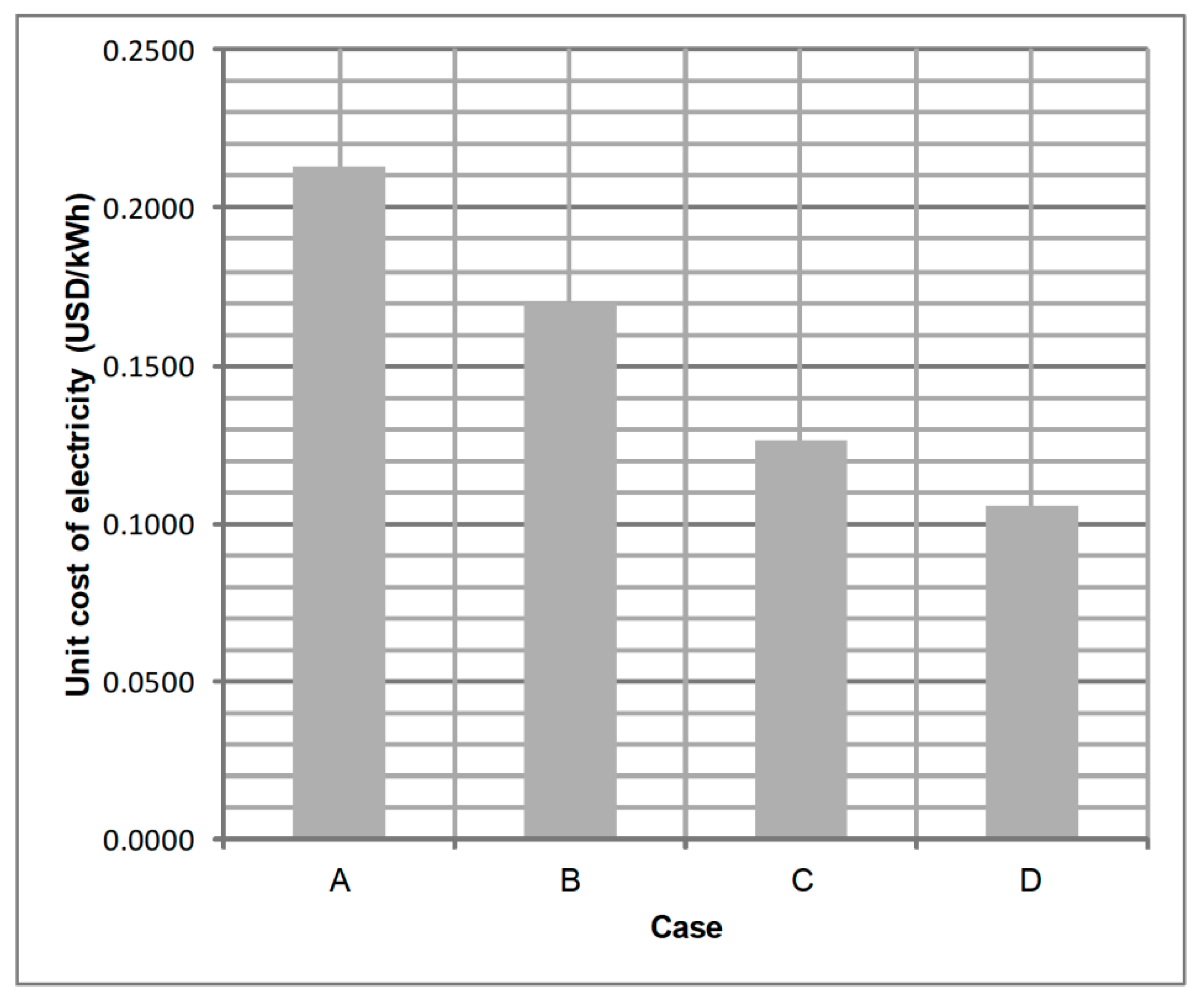
The cost analysis of the proposed system shows that in terms of capital cost, the highest cost is for the purchase of the SOFC subsystem (607,540 USD), while the cost for the PV arrays is 140,132 USD. The cost of the power subsystem, which is usually underestimated, is also significant at 221,951 USD. The total cost of fuel for the operation of the system during its lifetime is estimated at 891,735 USD. Although natural gas prices are constantly fluctuating, it is not expected that this cost estimation will be significantly altered in the near future for the EU market, based on a statistical review of the prices for the last 10 years [33]. The lifecycle cost for the system is 1,241,369 USD, with a unit cost of electricity at 0.1057 USD/kWh. The proposed system outperforms conventional and other system configurations, in terms of both the unit cost of electricity and CO
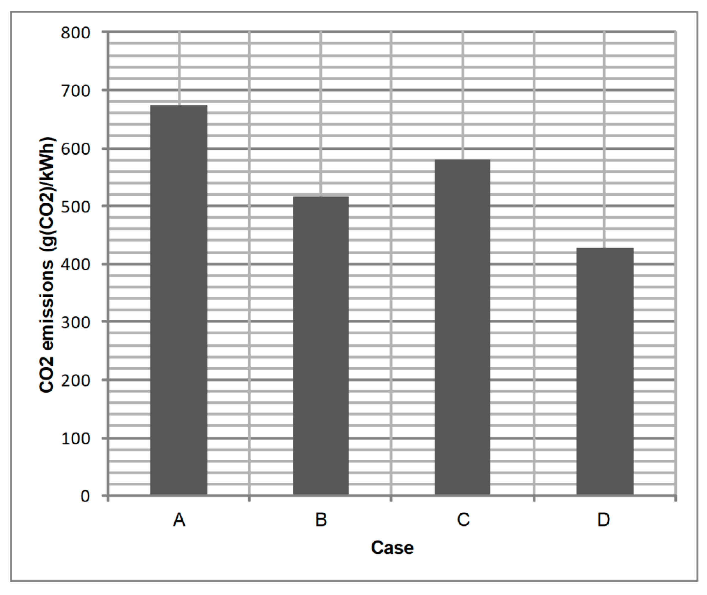
2 emissions. In comparison to the conventional case, the unit cost of electricity is about 50% lower (0.2128 vs. 0.1057 USD/kWh), while the reduction in CO2 emissions is about 36% (673 vs. 428 g(CO2)/kWh). The additional capital cost for purchasing the PV and the SOFC subsystems is well reasoned by the reduction in fuel consumption, hence on the unit cost of electricity. Similarly, in terms of CO2 emissions, the proposed system manages to significantly reduce emissions, because power generation is independent of the inefficient central power grid supply. Additionally, the integration of the PV subsystem allows a significant reduction in power generation from the SOFC subsystem during solar energy availability.

Author Contributions

Conceptualization, A.A.; Data curation, A.A.; Formal analysis, A.A.; Investigation, A.A.; Methodology, A.A.; Project administration, A.A.; Resources, G.E.G.; Software, A.A.; Supervision, G.E.G.; Validation, A.A.; Visualization, A.A.; Writing–original draft, A.A.; Writing–review & editing, A.A.

Funding

This research received no external funding.

Conflicts of Interest

The authors declare no conflict of interest.

Nomenclature and Units

A Activation area (m2)
A i Anisotropy index (-)
C Concentration of species (kmol m−3)
E o c v Open circuit voltage (V)
E ˙ Energy rate (W)
f Solar fraction (-)
F Faraday’s constant (Coulomb mol−1)
g Specific Gibbs free energy (J kmol−1)
h m Average diffusivity (m s−1)
i Current density (A m−2)
I Hourly irradiation (MJ m−2), Current (A)
I b Beam radiation (MJ m−2)
I d Diffuse radiation (MJ m−2)
I T Total incident solar radiation (MJ m−2)
K Reaction equilibrium constant (-)
n ˙ Molar flow rate (kmol s−1)
n c e l l s Number of cells (-)
n e Number of electrons transferred per H2 molecule reacted (-)
p Pressure (bar, Pa)
P Energy (kWh, MWh)
P ˙ Power (W)
Q ˙ Heat rate (W)
R Universal gas constant (J mol−1 K−1)
R b Ratio of beam radiation (-)
R i Ohmic resistance (Ω m2)
S C Steam-to-carbon ratio (-)
T Temperature (°C, K)
T E R Thermal-to-electric ratio (-)
U f Fuel utilization factor (-)
V Voltage (V)
X Conversion molar flow rate (kmol s−1)
y Mole fraction (-)
Greek symbols
α Charge transfer coefficient (-)
β PV tilt angle (degrees)
γ Activity coefficient (A m−2)
Δ g f 0 Gibbs free energy (J kmol−1)
Δ G Overall change in Gibbs free energy (J kmol−1)
η Efficiency (-)
μ m p Maximum power point efficiency temperature coefficient (-)
ρ g Ground reflectance (-)
Subscripts/Superscripts
0 Theoretical (ideal) value
a b Air blower
a c t Activation
a m b Ambient conditions
a n o Fuel cell anode
a r r a y Array
c PV array
c a t Fuel cell cathode
c e l l Cell
c o m p Fuel compressor
c o n c Concentration
c o o l Space cooling
d h w Domestic hot water
e l Electrical
e q u i p Interior equipment
e x c Excess
f a n Fans
f c Fuel cell
f c s Fuel cell subsystem
f u e l Fuel
h e a t Heat
H H V Higher heating value
i n Inlet flow
i n v Inverter
L Limiting
L H V Lower heating value
l i g h t Interior lights
l o a d Load
l o s s Loss
m p Maximum point
n e t Net value
N O C T Nominal operating cell temperature
o h m Ohmic
o u t Exit flow
p u m p Water pump
p v Photovoltaic
p v s Photovoltaic subsystem
r e f Reformer
r e f e r Reference state
s m r Steam methane reformer
s o f c Solid oxide fuel cell
t h Recovered heat from fuel cell
w g s Water gas shift
Abbreviations
CHPCombined-heat-and-power
EESEngineering Equation Solver
EUEuropean Union
HDKRHay-Davies-Klucher-Reindl
HExHeat exchanger
HHVHigher heating value
LHVLower heating value
LMTDLogarithmic Mean Temperature Difference
PEMFCProton exchange membrane fuel cell
PVPhotovoltaic
RESRenewable energy sources
SMRSteam methane reformer
SOFCSolid oxide fuel cell
WGSWater gas shift

References

  1. Moné, C.D.; Chau, D.S.; Phelan, P.E. Economic feasibility of combined heat and power and absorption refrigeration with commercially available gas turbines. Energy Convers. Manag. 2001, 42, 1559–1573. [Google Scholar] [CrossRef]
  2. Popli, S.; Rodgers, P.; Eveloy, V. Trigeneration scheme for energy efficiency enhancement in a natural gas processing plant through turbine exhaust gas waste heat utilization. Appl. Energy 2012, 93, 624–636. [Google Scholar] [CrossRef]
  3. Pelster, S.; Favrat, D.; von Spakovsky, M.R. The Thermoeconomic and Environomic Modeling and Optimization of the Synthesis, Design, and Operation of Combined Cycles With Advanced Options. J. Eng. Gas Turbines Power 2001, 123, 717–726. [Google Scholar] [CrossRef]
  4. Mamaghani, A.H.; Najafi, B.; Casalegno, A.; Rinaldi, F. Predictive modelling and adaptive long-term performance optimization of an HT-PEM fuel cell based micro combined heat and power (CHP) plant. Appl. Energy 2017, 192, 519–529. [Google Scholar] [CrossRef]
  5. Arsalis, A.; Kær, S.K.; Nielsen, M.P. Modeling and optimization of a heat-pump-assisted high temperature proton exchange membrane fuel cell micro-combined-heat-and-power system for residential applications. Appl. Energy 2015, 147, 569–581. [Google Scholar] [CrossRef]
  6. Gunes, M.B.; Ellis, M.W. Evaluation of Energy, Environmental, and Economic Characteristics of Fuel Cell Combined Heat and Power Systems for Residential Applications. J. Energy Resour. Technol. 2003, 125, 208–220. [Google Scholar] [CrossRef]
  7. Oyarzábal, B.; von Spakovsky, M.R.; Ellis, M.W. Optimal Synthesis/Design of a Pem Fuel Cell Cogeneration System for Multi-Unit Residential Applications–Application of a Decomposition Strategy. J. Energy Resour. Technol. 2004, 126, 30–39. [Google Scholar] [CrossRef]
  8. Oyarzábal, B.; Ellis, M.W.; von Spakovsky, M.R. Development of Thermodynamic, Geometric, and Economic Models for Use in the Optimal Synthesis/Design of a PEM Fuel Cell Cogeneration System for Multi-Unit Residential Applications. J. Energy Resour. Technol. 2004, 126, 21–29. [Google Scholar] [CrossRef]
  9. Weber, C.; Koyama, M.; Kraines, S. CO2-emissions reduction potential and costs of a decentralized energy system for providing electricity, cooling and heating in an office-building in Tokyo. Energy 2006, 31, 2705–2725. [Google Scholar] [CrossRef]
  10. Braun, R.J.; Klein, S.A.; Reindl, D.T. Evaluation of system configurations for solid oxide fuel cell-based micro-combined heat and power generators in residential applications. J. Power Sources 2006, 158, 1290–1305. [Google Scholar] [CrossRef]
  11. Liso, V.; Olesen, A.C.; Nielsen, M.P.; Kær, S.K. Performance comparison between partial oxidation and methane steam reforming processes for solid oxide fuel cell (SOFC) micro combined heat and power (CHP) system. Energy 2011, 36, 4216–4226. [Google Scholar] [CrossRef]
  12. Braun, R.J. Techno-economic optimal design of solid oxide fuel cell systems for micro-combined heat and power applications in the U.S. J. Fuel Cell Sci. Technol. 2010, 7, 310181–3101815. [Google Scholar] [CrossRef]
  13. Antonucci, V.; Branchini, L.; Brunaccini, G.; De Pascale, A.; Ferraro, M.; Melino, F.; Orlandini, V.; Sergi, F. Thermal integration of a SOFC power generator and a Na – NiCl 2 battery for CHP domestic application. Appl. Energy 2017, 185, 1256–1267. [Google Scholar] [CrossRef]
  14. Kurz, R. Parameter Optimization on Combined Gas Turbine-Fuel Cell Power Plants. J. Fuel Cell Sci. Technol. 2005, 2, 268–273. [Google Scholar] [CrossRef]
  15. Calise, F.; Palombo, A.; Vanoli, L. Design and partial load exergy analysis of hybrid SOFC-GT power plant. J. Power Sources 2006, 158, 225–244. [Google Scholar] [CrossRef]
  16. Calise, F.; Dentice d’ Accadia, M.; Vanoli, L.; von Spakovsky, M.R. Single-level optimization of a hybrid SOFC-GT power plant. J. Power Sources 2006, 159, 1169–1185. [Google Scholar] [CrossRef]
  17. Comodi, G.; Renzi, M.; Cioccolanti, L.; Caresana, F.; Pelagalli, L. Hybrid system with micro gas turbine and PV (photovoltaic) plant: Guidelines for sizing and management strategies. Energy 2015, 89, 226–235. [Google Scholar] [CrossRef]
  18. Arsalis, A.; Alexandrou, A.N.; Georghiou, G.E. Thermoeconomic modeling of a small-scale gas turbine-photovoltaic-electrolyzer combined-cooling-heating-and-power system for distributed energy applications. J. Clean. Prod. 2018, 188, 443–455. [Google Scholar] [CrossRef]
  19. Darghouth, N.R.; Wiser, R.H.; Barbose, G.; Mills, A.D. Net metering and market feedback loops: Exploring the impact of retail rate design on distributed PV deployment. Appl. Energy 2016, 162, 713–722. [Google Scholar] [CrossRef] [Green Version]
  20. Arsalis, A.; Alexandrou, A.N.; Georghiou, G.E. Thermoeconomic Modeling and Parametric Study of a Photovoltaic-Assisted 1 MWe Combined Cooling, Heating, and Power System. Energies 2016, 9, 663. [Google Scholar] [CrossRef]
  21. Kélouwani, S.; Agbossou, K.; Chahine, R. Model for energy conversion in renewable energy system with hydrogen storage. J. Power Sources 2005, 140, 392–399. [Google Scholar] [CrossRef]
  22. Darras, C.; Sailler, S.; Thibault, C.; Muselli, M.; Poggi, P.; Hoguet, J.C.; Melscoet, S.; Pinton, E.; Grehant, S.; Gailly, F.; et al. Sizing of photovoltaic system coupled with hydrogen/oxygen storage based on the ORIENTE model. Int. J. Hydrogen Energy 2010, 35, 3322–3332. [Google Scholar] [CrossRef]
  23. Arsalis, A.; Nielsen, M.P.; Kær, S.K. Application of an improved operational strategy on a PBI fuel cell-based residential system for Danish single-family households. Appl. Therm. Eng. 2013, 50, 704–713. [Google Scholar] [CrossRef]
  24. Mehr, A.S.; Gandiglio, M.; MosayebNezhad, M.; Lanzini, A.; Mahmoudi, S.M.S.; Yari, M.; Santarelli, M. Solar-assisted integrated biogas solid oxide fuel cell (SOFC) installation in wastewater treatment plant: Energy and economic analysis. Appl. Energy 2017, 191, 620–638. [Google Scholar] [CrossRef]
  25. Kim, K.; Von Spakovsky, M.R.; Wang, M.; Nelson, D.J. A hybrid multi-level optimization approach for the dynamic synthesis/design and operation/control under uncertainty of a fuel cell system. Energy 2011, 36, 3933–3943. [Google Scholar] [CrossRef]
  26. Kim, K.; Von Spakovsky, M.R.; Wang, M.; Nelson, D.J. Dynamic optimization under uncertainty of the synthesis/design and operation/control of a proton exchange membrane fuel cell system. J. Power Sources 2012, 205, 252–263. [Google Scholar] [CrossRef]
  27. Meteonorm 7; Meteotest AG: Bern, Switzerland, 2012.
  28. Open EI. Available online: https://openei.org (accessed on 7 May 2018).
  29. Duffie, J.A.; Beckman, W.A. Solar Engineering of Thermal Processes, 4th ed.; Wiley: Hoboken, NJ, USA, 2013. [Google Scholar]
  30. Arsalis, A. Thermoeconomic modeling and parametric study of hybrid SOFC-gas turbine-steam turbine power plants ranging from 1.5 to 10 MWe. J. Power Sources 2008, 181, 313–326. [Google Scholar] [CrossRef]
  31. Kolb, G. Fuel Processing for Fuel Cells; Wiley-VCH: Weinheim, Germany, 2008. [Google Scholar]
  32. Arsalis, A.; Nielsen, M.P.; Kær, S.K. Modeling and off-design performance of a 1 kWe HT-PEMFC (high temperature-proton exchange membrane fuel cell)-based residential micro-CHP (combined-heat-and-power) system for Danish single-family households. Energy 2011, 36, 993–1002. [Google Scholar] [CrossRef]
  33. Arsalis, A.; Nielsen, M.P.; Kær, S.K. Modeling and optimization of a 1 kW e HT-PEMFC-based micro-CHP residential system. Int. J. Hydrogen Energy 2011, 37, 2470–2481. [Google Scholar] [CrossRef]
  34. O’Hayre, R.; Colella, W.; Cha, S.-W.; Prinz, F.B. Fuel Cell Fundamentals, 2nd ed.; Wiley: Hoboken, NJ, USA, 2009. [Google Scholar]
  35. Larminie, J.; Dicks, A.L. Fuel Cell Systems Explained, 2nd ed.; Wiley: Chichester, UK, 2003. [Google Scholar]
  36. Arsalis, A.; Nielsen, M.P.; Kær, S.K. Modeling and parametric study of a 1 kWe HT-PEMFC-based residential micro-CHP system. Int. J. Hydrogen Energy 2011, 36, 5010–5020. [Google Scholar] [CrossRef]
  37. Dincer, I.; Zamfirescu, C. Sustainable Energy Systems and Applications; Springer: New York, NY, USA, 2011. [Google Scholar]
  38. GOV.UK Solar PV Cost Data. Available online: https://www.gov.uk/government/statistics/solar-pv-cost-data (accessed on 11 July 2018).
  39. Scataglini, R.; Mayyas, A.; Wei, M.; Chan, S.H.; Lipman, T.; Gosselin, D.; D’Alessio, A.; Breunig, H.; Colella, W.G.; James, B.D. A Total Cost of Ownership Model for Solid Oxide Fuel Cells in Combined Heat and Power and Power-Only Applications; Lawrence Berkeley National Laboratory: Berkeley, CA, USA, 2015.
  40. European Union Natural Gas Import Price. Available online: https://ycharts.com/indicators/europe_natural_gas_price (accessed on 3 July 2018).
  41. ASHRAE Handbook—HVAC Systems and Equipment; American Society of Heating, Refrigerating, and Air-Conditioning Engineers: Atlanta, GA, USA, 2008.
  42. Linderoth, S.; Larsen, P.H.; Mogensen, M.; Hendriksen, P.V.C.N.; Holm-Larsen, H. Solid Oxide Fuel Cell (SOFC) Development in Denmark. Mater. Sci. Forum 2007, 539–543, 1309–1314. [Google Scholar] [CrossRef]
  43. Arsalis, A.; Alexandrou, A.N.; Georghiou, G.E. Thermoeconomic modeling of a completely autonomous, zero-emission photovoltaic system with hydrogen storage for residential applications. Renew. Energy 2018, 126, 354–369. [Google Scholar] [CrossRef]
Figure 1. Schematic representation of the proposed hybrid photovoltaic-solid oxide fuel cell (PV-SOFC) system.
Energies 11 03512 g001
Figure 2. The load profile includes the following electrical loads (graph color in parenthesis): Fans (black), interior equipment (blue), interior lights (red), space cooling (green), space heating (purple), and domestic hot water (brown).
Energies 11 03512 g002
Figure 3. Validation of the modeled SOFC stack against literature data from [42].
Energies 11 03512 g003
Figure 4. Schematic representation of the four considered cases: (A) Power supply from a central power grid (conventional case), (B) power supply from a central power grid assisted with an on-site PV system, (C) power (and heat) supply from a decentralized SOFC system, and (D) power (and heat) supply from the proposed hybrid PV-SOFC system.
Energies 11 03512 g004
Figure 5. Comparison of the four cases under study in terms of the unit cost of electricity (in USD/kWh).
Energies 11 03512 g005
Figure 6. Comparison of the four cases under study in terms of CO2 emissions (in g (CO2)/kWh).
Energies 11 03512 g006
Table 1. System input parameters of the solid oxide fuel cell (SOFC) subsystem.
Parameter DescriptionValue
U f Fuel utilization factor0.92
A f c Fuel cell effective cross-sectional area144 cm2
n c e l l s Total number of cells in fuel cell stacks12,000
T f c Fuel cell operating temperature750 °C
T 6 Fuel preheater exit temperature450 °C
T 8 SMR reactor reformate exit temperature650 °C
T 13 Cathode inlet temperature650 °C
T 17 Combustor exit temperature1005 °C
T 22 HEx4 flue gas exit temperature55 °C
T 25 Water pump 1 inlet temperature40 °C
T 28 Hot water storage tank return temperature40 °C
T 29 Hot water storage tank supply temperature65 °C
S C Steam-to-carbon ratio2.5
Table 2. Cost modeling equations for the proposed hybrid system.
Variable Description (Unit)Model Equation
C f c Cost of SOFC subsystem (USD) N l t , f c , a d j = N l t , f c / z f c n r e = N l t / N l t , f c , a d j
C f c = n r e c f c s P ˙ f c , m a x
c f u e l Cost of fuel in the first year (USD) c f u e l = c $ M M B t u ( 3.6 / 3.41 ) [ $ / GJ ] |   1 × 10 9 $ / J $ / GJ   |
E p y Annual fuel consumption (J) E p y = E f u e l , i n , y r |   3600 J W h   |
c f y Annual cost of fuel (USD/year) c f y = E p y c f u e l
C p v Cost of PV arrays (USD) C p v = c p v s P ˙ p v , m a x
C i n v Cost of power subsystem (USD) C i n v = c i n v s ( P ˙ p v , m a x + P ˙ f c , m a x )
C s y s Total cost of system (USD) C s y s = C p v + C f c + C i n v + C h w s t
C d o w n Down payment (USD) C d o w n = ( 1 f l o a n ) C s y s
A P n Capital recovery factor (-) A P n = r n 1 - ( 1 + r n ) - N L T
r 1 = r m L i r 2 = r m L r 3 = r 2 r 1 0.01 + r 1 r 4 = r m L r e 1 + r e
P A n Uniform series present worth factor (-) P A n = ( A P n ) 1
F P n Compound amount factor (-) F P n = ( 1 + r n ) N L T
P F n Present worth factor (-) P F n = ( F P n ) 1
C l o a n Cost of the loan (USD) C l o a n = A P 1 A P 2 f l o a n C s y s
D l o a n Tax deduction on the loan (USD) D l o a n = t f l o a n C s y s ( A P 1 A P 2 A P 1 r 1 ( 1 + r 1 ) A P 3 )
C t w c Total worth of capital (USD) C t w c = C d o w n + C l o a n D l o a n
D d e p Linear depreciation of capital (USD) D d e p = t P A 2 ( C s y s / N L T )
D c r e d Tax credit (USD) D c r e d = t c r e d C s y s
D s a l v Salvage worth (USD) D s a l v = f s a l v C s y s P F 2 ( 1 t s a l v )
C p r o p Tax paid on property (USD) C p r o p = f p r o p C s y s t p r o p ( 1 t )
C o m i Operation, maintenance and insurance cost (USD) C o m i = f o m i C s y s P A 2 ( 1 t )
C t c f Total cost of fuel (USD) C t c f = c f y ( 1 t A P 4 )
L C C Life cycle cost (USD) L C C = C t w c + C p r o p + C o m i + C t c f ( D d e p + D c r e d + D s a l v )
c e l Unit cost of electricity (USD/kWh) P c s , l i f e = N l t P l o a d , y r
c e l = L C C / P c s , l i f e
Table 3. Parameters held constant in the cost model.
Parameter DescriptionValue
c p v s Specific cost of PV arrays2.00 USD/W
c f c s Specific cost of SOFC subsystem2.00 USD/W
c i n v s Specific cost of power subsystem1.00 USD/W
c $ M M B t u Cost of fuel (natural gas)7.19 USD/MMBTU
N l t System lifetime20 years
N l t , f c SOFC subsystem lifetime5 years
z f c Fuel cell operation factor0.50
C h w s t Cost of hot water storage tank5000 USD
r e Real fuel price escalation rate0.10
i Inflation rate0.01
r m Market discount rate0.06
r m L Market loan rate0.05
f l o a n Fraction of the capital cost paid through a loan0.80
t Incremental income tax0.40
t c r e d Tax credit0.02
f s a l v Salvage fraction0.10
t s a l v Salvage tax0.20
f p r o p Property fraction0.50
t p r o p Property tax0.25
f o m i Operation and maintenance fraction0.01
Table 4. Performance characteristics of the proposed hybrid PV-SOFC system.
Parameter DescriptionValue
P ˙ p v PV maximum power output70 kWe
P ˙ s o f c SOFC maximum power output152 kWe
η e l , n e t , L H V Net electrical efficiency of SOFC subsystem0.200 (full-load)
0.303 (average)
0.375 (maximum)
η f c s Total efficiency of SOFC subsystem0.659 (minimum)
0.700 (average)
0.756 (maximum)
T E R Thermal-to-electric ratio0.8 (minimum)
1.3 (average)
2.5 (maximum)
P p v s Annual electricity output of PV subsystem135.9 MWh
P f c s Annual electricity output of SOFC subsystem451.2 MWh
P t h Annual heat recovery from SOFC subsystem694.5 MWh
P h e a t , n e t Annual additional heat generation7.2 MWh
P l o a d Annual electricity load requirement587.1 MWh
E f u e l Annual fuel consumption1610 MWh
i f c , d e s Current density at design conditions1228 A/m2
η i n v , p v Inverter efficiency of PV subsystem0.961 (average)
η i n v , s o f c Inverter efficiency of SOFC subsystem0.970 (average)
U 1 Overall heat transfer coefficient of HEx190 W/m2·K
U 2 Overall heat transfer coefficient of HEx2292 W/m2·K
U 3 Overall heat transfer coefficient of HEx34960 W/m2·K
U 4 Overall heat transfer coefficient of HEx48396 W/m2·K
Table 5. Values for the thermophysical parameters of the proposed PV-SOFC hybrid system at full load conditions for the SOFC subsystem.
Node n ˙ (kg/s) p (Pa) T (K) y CH 4 y CO y CO 2 y H 2 y H 2 O y N 2 y O 2
10.0008130,0002980.0000.0000.0000.0000.0000.0000.000
20.0008138,0813030.0000.0000.0000.0000.0000.0000.000
30.0003119,8003030.0000.0000.0000.0000.0000.0000.000
40.0005138,0813030.0000.0000.0000.0000.0000.0000.000
50.0005128,0813030.0000.0000.0000.0000.0000.0000.000
60.0005126,8007230.0000.0000.0000.0000.0000.0000.000
70.0016126,8007230.2860.0000.0000.0000.7140.0000.000
80.0016121,8009230.0400.0800.0770.5460.2570.0000.000
90.0294101,3252980.0000.0000.0000.0000.0000.0000.000
100.0294101,3252980.0000.0000.0000.0000.0000.0000.000
110.0294124,0403200.0000.0000.0000.0000.0000.0000.000
120.0294122,8009230.0000.0000.0000.0000.0000.0000.000
130.0294122,8009230.0000.0000.0000.0000.0000.0000.000
140.0000119,8009230.0000.0000.0000.0000.0000.0000.000
150.0017119,80010230.0020.0390.1420.0550.7630.0000.000
160.0288119,80010230.0000.0000.0000.0000.0000.8050.195
170.0308117,80012780.0000.0000.0200.0000.0660.7530.160
180.0308115,30011920.0000.0000.0200.0000.0660.7530.160
190.0308114,14711830.0000.0000.0200.0000.0660.7530.160
200.0308113,00611210.0000.0000.0200.0000.0660.7530.160
210.0308111,8755860.0000.0000.0200.0000.0660.7530.160
220.0308110,7573280.0000.0000.0200.0000.0660.7530.160
230.0287110,7573280.0000.0000.0220.0000.0000.8070.171
240.0020110,7573280.0000.0000.0000.0000.0000.0000.000
250.0012101,3253130.0000.0000.0000.0000.0000.0000.000
260.0012128,0813130.0000.0000.0000.0000.0000.0000.000
270.0012126,8007230.0000.0000.0000.0000.0000.0000.000
280.1743110,0003130.0000.0000.0000.0000.0000.0000.000
290.1743108,9003380.0000.0000.0000.0000.0000.0000.000
300.1743120,0003380.0000.0000.0000.0000.0000.0000.000
Table 6. Cost analysis of the proposed hybrid PV-SOFC system.
Output Parameter DescriptionValue
c f y Annual cost of fuel43,995 USD/year
C p v Cost of PV arrays140,132 USD
C f c Cost of SOFC subsystem607,540 USD
C i n v Cost of power subsystem221,951 USD
C s y s Total cost of the system974,623 USD
C d o w n Down payment194,925 USD
C l o a n Cost of the loan714,977 USD
D l o a n Tax deduction on the loan236,951 USD
C t w c Total worth of capital672,950 USD
D d e p Depreciation of capital242,919 USD
D c r e d Tax credit19,492 USD
D s a l v Salvage worth206,877 USD
C p r o p Tax paid on property73,097 USD
C o m i Cost of operation, maintenance and insurance72,876 USD
C t c f Total cost of fuel891,735 USD
L C C Lifecycle cost1,241,369 USD
c e l Unit cost of electricity0.1057 USD/kWh

