Article

Energy Efficiency Analysis of Multi-Type Floating Bodies for a Novel Heaving Point Absorber with Application to Low-Power Unmanned Ocean Device

1
School of Intelligent Science, National University of Defense Technology, Changsha 410073, China
2
School of Mechanical and Electronic Engineering, Shandong Jianzhu University, Jinan 250101, China
*
Author to whom correspondence should be addressed.
Energies 2018, 11(12), 3282; https://doi.org/10.3390/en11123282
Submission received: 2 September 2018 / Revised: 11 November 2018 / Accepted: 21 November 2018 / Published: 25 November 2018
(This article belongs to the Special Issue Wave and Tidal Energy)

Abstract

:
Long-term energy supplies hinder the application of the low-power unmanned ocean devices to the deep sea. Ocean wave energy is a renewable resource with amount stores of enormous and high density. The wave energy converter (WEC) could be miniaturized so that it can be integrated into the devices to make up the power module. In this paper, a small novel heaving point absorber of energy supply for low-power unmanned ocean devices is developed based on the counter-rotating self-adaptive mechanism. The floating body as an important part of the heaving point absorber, the geometric parameters is optimized to increase the efficiency of power production. Through constructing the constitutive relation between the geometric parameters, the wave force, the motion displacement, the motion velocity, and the capture width ratio of the floating body, the energy efficiency characteristics of the multi-type floating bodies are calculated, and the optimal shape is selected. On the other hand, in the calculation process of the wave force, the Froude-Krylov method is an effective method to accurately calculate the wave excitation force. Meanwhile, nonlinear static and dynamic Froude-Krylov force effectively overcomes the inaccuracy of the linear models and reduces the time consumed to simulate. Finally, the wave force, heaving velocity, heaving displacement, and capture width ratio of the three floating bodies are compared and analyzed, and the results show that the cylindrical floater that is vertically placed on the wave surface is more suitable for the novel heaving wave energy point absorber.

1. Introduction

Low-power unmanned ocean device, such as unmanned surface/under water vehicles, ocean robots, and ocean buoys are widely used in unmanned combat, deep-sea exploration, and marine communications, and so on [1,2,3,4,5]. With the continuous development of deep sea and offshore strategies, the scope of work of low-power unmanned ocean devices continues to expand [6]. Long-term, stable, and reliable energy supply is the basis for the rapid development of low-power unmanned ocean device [7]. Currently, the common energy supply technology is a battery. However, its energy density is low and it is necessary to carry multiple batteries to meet the requirements. The device space is limited, which limits the amount of battery that is carried [8]. Therefore, it is difficult for the battery to meet the requirements of the long-range and long-life capability of the current low-power unmanned ocean device. Therefore, studying the energy supply technology of high energy density and improving the long range and long battery life of the ocean device is the fundamental guarantee for effectively solving the application of low-power unmanned ocean device to the deep sea [9].
The ocean covers about 70% of the Earth’s surface, making it the world’s largest solar collector and energy storage system [10]. There are many types of renewable resources for ocean storage, such as Wave Power, Tidal Power and Tidal Current Energy, Ocean Thermal Energy Conversion (OTEC), and Salinity Gradient Energy. We can convert them into electricity by means of a power generator [11]. Wind blowing over the surface of the ocean creates waves that can be harvested for energy and creates uninterrupted, continuous wave energy in the Ocean’s surface [12]. The amount of wave power that is stored by the ocean is enormous and high density. Theoretically, the global wave power resource is 2.11 ± 0.05 TW, of which 4.6% is extractable with the chosen WEC configuration [13,14]. Therefore, wave energy is the most ideal resource for a low-power unmanned ocean device.
The utilization of wave energy goes far back in time—people using wave push water mill taken place in the 1200 s. The world’s first wave energy technology patent is filed by Frenchman Girard and his son in 1799 [15]. In 1910, the Frenchman Pocec-Plesic built the world’s first wave energy converter (WEC) on the coast, namely air turbine private power station with a capacity of 1kW [10]. Salter of the University of Edinburgh successfully developed a duck-type WEC, and first published an article entitled “Wave Power” in Nature in 1974 [16]. However, due to the unsolved technical problems, such as the economy and stability of WEC, the research progress of wave energy technology was slower in the 1980s and early 1990s. In the last 20 years, with the emergence of problems, such as energy depletion, environmental pollution, and the greenhouse effect, the development of green and renewable energy has become the mainstream [7]. Wave energy has regained rapid growth under the guidance of the government, especially in some mariner countries, such as Ireland, Denmark, Norway, and UK [17,18,19,20].
WEC’s are generally categorized by the method that is used to capture the energy of the waves, by location and by the power take-off (PTO) system [10,21]. Locations are shoreline, near shore, and offshore. Types of power take-off include: hydraulic ram, elastomeric hose pump, pump-to-shore, hydroelectric turbine, air turbine, and linear electrical generator. In addition, WEC’S can also be categorized by the energy transfer method, namely point absorber, surface attenuators, oscillating water columns, and overtopping devices.
Comparative and analytic research on the working principle of current WEC’s, the point absorber is the best choice for the power supply of low-power unmanned ocean device [7]. However, the research on point absorber is mainly focused on large-scale grid-connected generation in shore and near shore, and the dimension of the device is larger, and the power generation operation is more complicated [10]. At present, typical point absorber includes Power Buoy [22], Wave bob [23], Sea Based [24], Fred Olsens Lifesaver [25], and Carnegies CETO [26]. The shape dimension of them is very large, such as Power Buoy, where the diameter of the buoy is about 3 m and the overall height about 14 m. As the characteristics, such as concealment, camouflage, small dimension, wide and far working area of low-power unmanned ocean device, and the huge dimension of the above point absorbers, makes it still difficult to provide a satisfactory power source for it.
Considering the technical requirements of the power supply for the low-power unmanned ocean device and the current research state of power generation technology, we developed a small novel heaving point absorber that is based on the counter-rotating self-adaptive mechanism, with the advantages of small space device and a stable and reliable energy conversion process [7]. It is an ideal WEC of power supply for the low-power unmanned ocean device, so as to increase their working hours and improve independent operation ability.
Previous work shown that the influence law of the blade angel on the impeller speed was obtained and the model prototype was trial produced base on the study of the blade angle and the relative speed of the upper and lower impellers for the Underwater PTO [7].The adjustment of the blade angle in impellers is passive action. The move displacement of the floating body and the Underwater PTO affects the deflection angle. The locking devices of the impellers limit the angle. In addition, previous works show that the maximum blade deflection angles between 35° and 55° are the best efficiency characteristics [7]. In order to increase the power production of the novel heaving point absorber, it is necessary to increase the elevation of the Underwater PTO in the vertical direction, that is, increase the heave amplitude of the floating body. Because the displacement of the body is performed by its immersion depth, shape, and dimension, so the geometric parameters of the body are optimized, which is of great significance for increasing the power production of the novel heaving point absorber.
The floating body dynamics of the WEC have been investigated by many researchers. For example, Black et al. [27] comparatively analyzed the wave radiation forces and scattering forces for horizontal rectangular and vertical circular cylinders using the Haskind’s theorem. Mohapatra and Guedes Soares [28] studied the wave forces on a two-dimensional rectangular floating structure based on linearized Boussinesq. Rodriguez et al. [29] investigated the numerical nonlinear heave response of a rectangular box concerning the importance of the relative body dimensions. Islam et al. [30] analyzed the wave radiation of a heaving box-type floating structure based on CFD simulations with a volume of fluid method. Yeung et al. [31] and Sabuncu et al. [32] discussed the added mass and damping of a vertical cylinder in finite depth water. Calisal et al. [33] presented an efficient method of hydrodynamic coefficients calculation for vertical composite cylinders at finite depth. Mansour et al. [34] analyzed the diffraction of linear waves by a uniform vertical cylinder with cosine-type radial perturbations. Bhata et al. [35] studied scattering and radiation problems for a cylinder on nonlinear wave loading at finite depth. Kim [36] researched the hydrodynamic coefficients of the floater with elliptical cylinder and ellipsoid on a free surface. Bihs et al. [37] simulated a horizontal cylinder in heave motion and the motion of a freely floating rectangular barge in waves using the CFD model and compared the results with experimental data. Koh et al. [38] used Matched Eigenfunction Expansion Method (MEEM) to solving the radiation problem of the heaving circular cylinder in the context of linear potential theory. Wang sheng [39] discussed the added mass and damping of an ellipsoid in infinite and finite depth water. Finnegan et al. [40] determined an analytical approximation for the wave excitation forces on a floating truncated vertical cylinder in water of infinite depth and solved the appropriate boundary value using the method of separation of variables. Ghadimi et al. [41] presented a detailed analytical solution for the boundary value problem to evaluate the wave loads for the cylinder with heave and pitch motions in water of finite depth in the presence of an incident wave. Although the floating body dynamics of the WEC are more researched, the energy efficiency of multi-type floating bodies in the heaving wave energy point absorber is poorly studied. Furthermore, in the above paper, the separation variable method and the eigenfunction expansion method is usually used for the calculation of the radiation force and diffraction force of the buoy base on the potential flow theory. However, it is difficult to solve their analytical solutions and is often time consuming to calculate.
Under the Airy’s wave theory, the Froude-Krylov approximation method is implemented to solve the wave force when the device dimension is considerably smaller than the wave length [42]. Froude-Krylov approximation method [33,34,35,36,37,38,39,40,41,42,43,44,45] is assumed that the original wave pressure distribution of the incident wave does not change due to the presence of the floating body. Therefore, wave excitation force is the product of the force of the undisturbed incident wave pressure on the floating body (dynamic Froude-Krylov force) and the diffraction correction coefficient. The diffraction coefficients reflect the attached mass effect and diffraction effects, which is determined by the model test. Although this method is an approximation method, it is simple to calculate and it is a very practical method for estimating the wave force. Moreover, because the method is built on model tests, accurate calculations can be obtained [42]. Falnes and Perlin [46,47] analyze the oscillating bodies in low-amplitude waves and obtain that the diffraction is negligible when the device dimension is considerably smaller than the wave length. Clement and Ferrant [48] described a method for the computation of free surface flows generated by submerged bodies, and obtain that radiation nonlinearities are negligible for floating bodies that are small as compared to the wave length. Merigaud et al. [43] added specific nonlinear terms to hydrodynamic models for wave energy devices, to improve the validity of such models across the full operational spectrum, showing that the response of the device is mainly affected by nonlinear FK forces, while nonlinear radiation and diffraction forces have minor effects on the system dynamics.
The focuses of the paper is on the novel heaving point absorber operating in the power production region, using the Froude-Krylov method to optimal shape design and maximize energy capture of the floating body for the power supply of the low-power unmanned ocean device. The remainder of this paper is organized as follows: Section 2 introduces the structure model of the novel heaving point absorber. Section 3 gives the mathematical model of the floating body of the novel absorber. Section 4 presents the algebraic solution of the wave excitation force in the vertical direction of floating bodies and nonlinear Froude-Krylov force integral. The numerical simulation and simulation analysis for the wave force, heaving velocity, heaving displacement, and capture width ratio of the multi-type floating bodies are in Section 5 and Section 6. Some conclusions and final remarks are presented in Section 7.

2. Structure Model

The waves are generally generated by wind blowing across the surface of the ocean. The motion of waves is regular and periodic on the water surface, with the amplitude decreasing exponentially with depth. When the depth to be greater than half the wavelength, the wave-induced motions is only approximately 4% of those at the surface and thus could be considered to be insignificant [10]. Therefore, this depth range is defined as the hydrostatic layer, in which the motion of waves is hardly perceived as the depth increases. Based on the above characteristics of wave motions, a novel heaving wave energy point absorber is designed, which can be used as a power module for the low-power unmanned ocean device [7]. Figure 1 shows the working scene of this point absorber. First, when the low-power unmanned ocean device is working on the ocean surface, the value of the battery energy is decreasing from the maximum to the lowest safe. Secondly, utilizing the release mechanism of the low-power unmanned ocean device, the novel heaving point absorber is released. The Underwater PTO subsystem of this absorber converts the captured wave energy into electricity. The value of the battery energy reaches the highest energy. Finally, utilizing the recovery mechanism of the ocean device, the absorber is recovered. The above process cycles back and forth, of which ensures the energy supply of unmanned ocean device for long-range and long-term work.
The system configuration and working principle of the novel heaving point absorber are illustrated in Figure 2. The absorber mainly includes two parts, a floating body and an Underwater PTO, which are connected with each other by a steel cable. The floating body floats on the ocean surface and the Underwater PTO suspends the hydrostatic layer at a depth of about 40 m. The Underwater PTO mainly consists of a power generator, upper impeller, lower impeller, steady blade, and transmission shaft and planet-gear increaser. The impellers are mainly composed of blades, connecting rods, locking devices, center wheels, and external fixation rings. The center wheel and the external fixation ring are connected by eight radials arranged in connecting rods. Eight fan-shaped blades are fixed on corresponding connecting rods with locking devices and are arranged in a centrally symmetric circumferential array. In addition, the steel cable not only acts as dragging the Underwater PTO, but also transmissions electricity and control signals.
The working principle of the novel heaving point absorber is shown in Figure 2. (1) During the movement of the floating body from the wave trough to the wave crest, the Underwater PTO is pulled up by the steel cable. The upper surface of the blade is impacted by the water flow and the blade adaptively swings downward, as shown in Figure 2a. Due to the limitation of the locking devices, the blade then stops swinging and is in a slanted state after reaching the maximum angle of inclination. The water flow continues to impact the slanted blades and propel the blade forward. The circumferential array of the blades enables the impeller to be subjected to circumferential thrust. Since the blades of the upper and lower impellers are arranged in opposite directions, the upper impeller is clockwise rotated by the water flow and the lower impeller is anticlockwise rotated by the water flow, and they are relatively reversed. The upper and lower impellers are fixedly connected with the stator and rotor of the generator, respectively, and then drive the generator to generate electricity. (2) During the movement of the floating body from the wave crest to the wave trough, the Underwater PTO sinks under the influence of gravity. The lower surface of the blade is impacted by the water flow and the blade adaptively swings upward, as shown in Figure 2b. Due to the limitation of the locking devices, the blade then stops swinging and it is in a slanted state after reaching the maximum angle of inclination. Since the direction of the water flow impinging on the blade does not change, the water flow continues to impact the slanted blades and propel the blade forward. The upper impeller is continuously clockwise rotated by the water flow and the lower impeller is continuously anticlockwise rotated by the water flow. Therefore, the direction of rotation of the generator does not change and it continues to generate electricity. According to the different impact directions of water flow, the impellers’ blades adaptively adjust the blade deflection. The upper and lower impellers act as components that interact directly with the water flow and they provide continuous rotational motion to the generator during rising and sinking of the Underwater PTO.

3. Mathematical Model

The floating body is an important part of the novel heaving wave energy point absorber and is in direct contact with the waves on the ocean surface. In order to increase the energy harvesting of floating body, it is necessary to increase the heave amplitude, heave velocity, and wave force in the vertical direction. It can increase the rising and sinking amplitude of the Underwater PTO and the relative rotational speed of the upper and lower impellers. Moreover, the power production of the novel heaving point absorber can also be increased. This section analysis of the force of the floating body, establishes its motion equation, and solves its wave excitation force and the Underwater PTO damping force. Also, this section derives the model of energy conversion efficiency between the floating body and the wave energy, and calculates its energy conversion efficiency.
The hydrodynamics model and energy efficiency model of the floating body is established to calculate the wave force and the conversion efficiency: Section 3.1 considers nonlinear Froude-Krylov force in the vertical direction and Underwater PTO damping force for the force analysis of the floating body in micro-wave amplitude. Section 3.2 presents the capture width ratio of the floating body for the energy efficiency analysis.

3.1. Hydrodynamics Model of the Floating Body

We consider that the floating body of the novel heaving point absorber floats freely in water of uniform depth. Under the action of linear regular waves, the floating body does micro amplitude heave motion. The fluid is assumed inviscid and the incident flow irrotational and incompressible. Figure 3 is the coordinates and force analysis of the floating body. The right-handed inertial reference frame is centered at the hydrostatic equilibrium position of the body. X is the vertical distance from the reference fluid surfaces to the body waterline (positive downwards). Y is the vertical distance from the reference fluid surface to the fluid surface (positive downwards). Y = r cos φ t , where r is the wave amplitude and φ is the wave angular frequency. Z is the vertical distance from the reference fluid surface to any point in the fluid (positive downwards). D is the waterline depth of the floating body. Newton’s second law can be used to describe the system dynamics, as follows:
m X ¨ ( t ) = G S ( t ) P ( t ) n d S Q I + F PTO ( t )
where, m is the mass of the novel heaving point absorber, X is the heaving displacement of the body from its hydrostatic equilibrium position, X ¨ is the heaving acceleration of the body, G the gravity force, S the submerged surface, P the pressure, n a vector normal to the surface, Q the viscous damping force, I the inertia force of attached mass effect, and F PTO the Underwater PTO damping force.
The pressure P can be derived from the incident flow applying Bernoulli’s equation:
P ( t ) = ρ g z ( t ) ρ ϕ ( t ) t ρ | ϕ ( t ) | 2 2
where, ρ the water density, g the acceleration of gravity, P st = ρ g z , hydrostatic pressure and ϕ the potential flow, which can be decomposed as the sum of the undisturbed incident flow potential ϕ I , the diffraction potential ϕ D , and the radiation potential ϕ R :
ϕ = ϕ I + ϕ D + ϕ R
The Airy’s wave theory assumes that the motion of the floating body is a small amplitude. The solution of Equation (1) is solved around the equilibrium position of the buoy. Under the linear assumption, the wetted surface is constant. However, the nonlinear of Froude-Krylov forces to be considered in the actual calculation process. Thus, the wetted surface is exactly instantaneous, namely integrating the fluid pressure over the actual submerged portion of the buoy, as it moves through the water. Froude-Krylov forces include the static and dynamic forces. They depend on the instantaneous wetted surface, which depends both on the incident wave elevation and the displacement of the buoy. Froude-Frylov force can be written as:
F F K = F F K st + F F K dy = S ( t ) ( P st ( t ) + P dy ( t ) ) n d S
where, F F K st is the static Froude-Krylov force, given as the balance between the gravity force and the Archimedes force, and F F K dy is the dynamic Froude-Krylov force.
F F K st = S ( t ) P st ( t ) n d S = S ( t ) ρ g z d S
F F K dy = S ( t ) P dy ( t ) n d S
where, P dy = ρ ϕ I t ρ | ϕ I | 2 2 is the dynamic pressure.
The time-dependence annotation will be omitted for brevity hereafter. Equation (1) can be rewritten as [42]:
m X ¨ = G + F F K + F D + F R + F PTO
where, F D is the diffraction force and F R is the radiation force.
Note that, since the fluid is assumed to be inviscid, irrotational, and incompressible, no viscous force and inertia force appears in Equation (7). In addition, due to Froude-Krylov force already includes the inertia force that is caused by the attached mass effect, the inertia force also does not appear in this Equation.
Wave excitation force is the force of wind blows the waves to disturb the motion of the floating body on the ocean surface. This force can be written as:
F ex = C F F K dy + F D
where, C is the diffraction correction coefficient.
The linear approach assumes that radiation and diffraction forces are linear. Therefore, the radiation and diffraction potential is negligible when the floating body dimension is considerably smaller than the wave length [43,44,45,46,47,48]. When combining Equations (4)–(8), Equation (1) can be rewritten as:
m X ¨ = C S ( t ) P dy n d S + F PTO
The algebraic calculation of the integral in Equation (9) requires the explicit definition of the dynamic pressure P dy , the infinitesimal surface element n d S , and the limits of integration. Under the Airy’s wave theory for deep water waves, the dynamic pressure at any point on the floating body in the local coordinate system can be written as:
P dy = ρ g H 2 c h k z ¯ c h k d cos ( k x ¯ ω t )
where, H is wave height, x ¯ is the direction of wave propagation in the local coordinate system, z ¯ is the vertical displacement of the floating body in the local coordinate system (positive upwards), and d is water depth and ω is the wave circular frequency. Wave Number k is defined by the dispersion equation k tanh ( k d ) = ω 2 / g .
During the motion of the novel heaving point absorber on the ocean surface, the coordinates at any point on the floating body in the global coordinate system can be written as:
[ x y z ] = [ X 0 Y 0 Z 0 ] + [ T ] [ x ¯ y ¯ z ¯ ]
where, ( X 0 , Y 0 , Z 0 ) is the coordinates of the center of gravity on the floating body in the global coordinate system and ( x ¯ , y ¯ , z ¯ ) is the coordinates at any point on the floating body in the local coordinate system. [ T ] is coordinate transformation matrix between the local coordinate system and global coordinate system.
Therefore, the dynamic pressure at any point on the floating body in the global coordinate system can be written as:
P dy = ρ g H 2 c h k ( d z ) c h k d cos ( k ( x + x ¯ ) ω t )
where, x is the direction of wave propagation in the global coordinate system and z is the vertical displacement of the floating body in the global coordinate system (positive upwards).
Furthermore, the force components of the wave excitation force in the vertical direction can be written as the following:
F ex z = C V S ( t ) P dy n z d S
where, n z is the projection of the normal for the wetted surface of the floating body in the vertical direction and C V is the diffraction correction coefficient in the vertical direction.
Under the movement of the novel heaving point absorber on the ocean surface, the heave motion of the floating body does work by overcoming the damping of the water. The Underwater PTO subsystem of this absorber converts the captured wave energy of the body into electricity. In the motion model of this absorber under the Airy’s wave theory, the linear damping model is used to analyze the damping force of the Underwater PTO system. Thus, the Underwater PTO damping force can be written as:
F PTO = B PTO X ˙
where, B PTO is the Underwater PTO damping coefficient and X ˙ is the heaving velocity of the floating body.

3.2. Energy Efficiency Model of the Floating Body

In the researches of the WEC, the performance of power production of the device is mainly concentrated on the energy harvesting and energy conversion. Using the capture width ratio [49,50] of the floating body as an evaluation index to measure the characteristic of energy harvesting and conversion efficiency for the novel heaving point absorber. The capture width ratio is that the ratio of the average power of the energy harvesting to the wave energy of the incident wave within the width of the body, namely the efficiency of energy harvesting in the WEC. It can be written as the following:
η = P W E C P 0
where, P W E C is the average power of the floating body to harvests wave energy and P 0 is the wave energy of the incident wave within the width of the body.
The average power of the energy harvesting is that the instantaneous power is integrated in a period and it solves the average value. It can be written as:
P W E C = 1 T 0 T F wave V W E C d t
where, F wave is the wave force, V W E C is the velocity of the floating body, and T is the wave period.
The average power of the energy harvesting in the vertical direction of the floating body can be written as:
P W E C z = 1 T 0 T ( F ex z + F PTO z ) X ˙ d t = 1 T 0 T ( ( C V S ( t ) P dy n z d S + B PTO z X ˙ ) X ˙ ) d t
where, F PTO z is the Underwater PTO damping force in the vertical direction and B PTO z is the Underwater PTO damping coefficient in the vertical direction.
The wave energy of the incident wave within the width of the floating body can be written as the following:
P 0 = ρ g H 2 ω 16 k [ 1 + 2 k d s h ( 2 k d ) ] B
where, B is the heading wave width of the floating body.

4. Algebraic Solution

The characteristic parameters, such as profile parameters, immersion depth, and wetted surface distribution, play an important role in the performance analysis, structural design, manufacture, and employment of the floating body. These parameters affect the motion amplitude, motion velocity, wave force, and wave energy harvesting of the floating body. Therefore, selects the profile parameters and solves the algebraic solution of the wave force is critical. Geometry shapes of floating body are two types of axisymmetric and unaxisymmetric. The axisymmetric body is a curved surface body formed by a generatrix rotating around a fixed vertical axis. The shape of the axisymmetric body is dependent on the shape of generatrix and relative position of the generatrix and the fixed axis. The axisymmetric bodies include cylinder, cone, sphere, and so on. The unaxisymmetric body is formed by a non-rotating curved surface. This body consists of rectangular, trapezoid, polyprism, and so on. In this paper, three kinds of shapes are selected for the floating body, such as rectangular, cylinder, and sphere. This section mainly solves the algebraic solution of the wave force of the above shape. Table 1 show that the algebraic solutions of the wave excitation force in the vertical direction of multi-type floating bodies. The geometric parameters of the axisymmetric body are described in cylindrical coordinates [42]. The axisymmetric bodies are described in rectangular coordinates.

5. Numerical Results

Based on the above analysis of the hydrodynamic performance and energy conversion characteristic for the multi-type floating bodies of the novel heaving wave energy point absorber, the wave force, heaving velocity, heaving displacement, and capture width ratio of the multi-type floating bodies were numerically simulated and comparatively analyzed.
During the numerical simulation, the parameters of the multi-type floating bodies are as follows: the length of horizontal rectangular a is 0.3 m, the length along the wave direction of horizontal rectangular b is 0.3 m, the height of horizontal rectangular c is 0.5 m, the radius of vertical cylinder R is 0.3 m, the height of vertical cylinder l is 0.5 m, the radius of sphere R is 0.3 m, the mean immersion depth is 0.15 m, the Underwater PTO damping coefficient in the vertical direction B PTO z is 20 KNs/m, and the mass of the novel heaving point absorber m is 10 kg. According to the model test results of previous research [51,52,53], the diffraction correction coefficient in the vertical direction C V of horizontal rectangular, vertical cylinder, and sphere can be obtained, respectively.
In this study, three reference sea states are used for evaluation the energy efficiency of the novel heaving wave energy point absorber. Sea state 1: the significant wave height H S is 0.1 m, the peak wave period T P is 2 s; Sea state 2: the significant wave height H S is 0.3 m, the peak wave period T P is 3.5 s; and, Sea state 3: the significant wave height H S is 0.5 m, the peak wave period T P is 5 s. The first sea state covers H S values from 0.0 to 0.1 m, the second sea state covers H S values from 0.1 to 0.3 m, and the third sea state covers H S values from 0.3 to 0.5 m. The combination of H S and T P is representative for the same wave tank, the wave climate date come from the simulation test. The model scales of the novel heaving point absorber, as follows: the Underwater PTO’s diameter is 410 mm, the distance between the upper and lower impeller is 400 mm, and the overall height of the Underwater PTO is about 560 mm. The scale between the dimensions of the tested heaving point absorber and the full scale device is 1:5. Another, the significant wave height H S is about 2.5 m in the real wave climate with the full scale device. The considered reference water depth d is 50 m. In addition, the incident wave is the linear regular wave, the angle between the direction of the linear regular wave and the direction of the novel heaving point absorber is 0°. According to the above parameters of the incident wave, the working scene of the novel heaving point absorber is the deep-water waves. Therefore, the other parameters of the incident wave are obtained, including wavelength, wave velocity, and velocity of water particles. These parameters are as follows: the wavelength is 6.2/19/39 m, the wave velocity is 3.1/5.5/7.8 m/s, and the velocity of water particles is 0.16/0.27/0.31 m/s.
The results of numerical simulation are shown in Figure 4, Figure 5, Figure 6, Figure 7, Figure 8, Figure 9, Figure 10 and Figure 11. The wave force, heaving velocity, heaving displacement, and capture width ratio of the multi-type floating bodies in the second sea state is shown in Figure 4, Figure 5, Figure 6 and Figure 7, respectively. Figure 8, Figure 9, Figure 10 and Figure 11 show that the above parameters for comparison in the three reference sea states and the values obtained from the numerical simulation.

6. Discussion

As shown in Figure 4, Figure 5 and Figure 6, the vibration frequency curve of the wave force, heaving velocity, and heaving displacement are less of the same for the vertical cylinder buoy and the sphere buoy. However, as to the former, the curve of the wave force and the heaving displacement is steeper, the heaving velocity is faster, wave follower is better, and the generated energy is higher. Nevertheless, the wave force and heaving displacement of the horizontal rectangular floating body are smaller than those two types of floating bodies. Therefore, the generated energy and wave follower is weaker by this one less than those two types of floater bodies. In Figure 7, the capture width ratio of the vertical cylinder floating body is higher and more stable than the sphere floating body. While, the horizontal rectangular floating body is much more less than those two types of floating bodies.
In addition, as shown in Figure 8, Figure 9, Figure 10 and Figure 11, the wave force, heaving velocity, heaving displacement, and capture width ratio of the floating bodying is affected by the peak wave period and the wave height at a certain sea state. The above parameters are become higher when the sea state increases. Another, the vertical cylinder floating body outperforms the other floating body in the three reference sea states. As shown in Figure 11, the curve of the capture width ratio is steeper and the value of this parameter is higher when the sea state big changes.
In summary, with the linear regular wave, the cylindrical floater vertically placed in the wave surface is the first optional shape for the novel heaving point absorber and follower is the sphere floater, which can increase the quality of power extracting and the efficient of the WEC system design. At last, the horizontal rectangular floating body is carefully selected.

7. Conclusions

This paper presents a small novel heaving point absorber of energy supply for low-power unmanned ocean devices that are based on the counter-rotating self-adaptive mechanism, with the advantages of small space device, stability, and reliable energy conversion process. For improving the efficiency of this absorber’s power production, the wave force and energy efficiency are analyzed by the Froude-Krylov method and the optimal floating body is selected, the following conclusions are drawn:
(1)
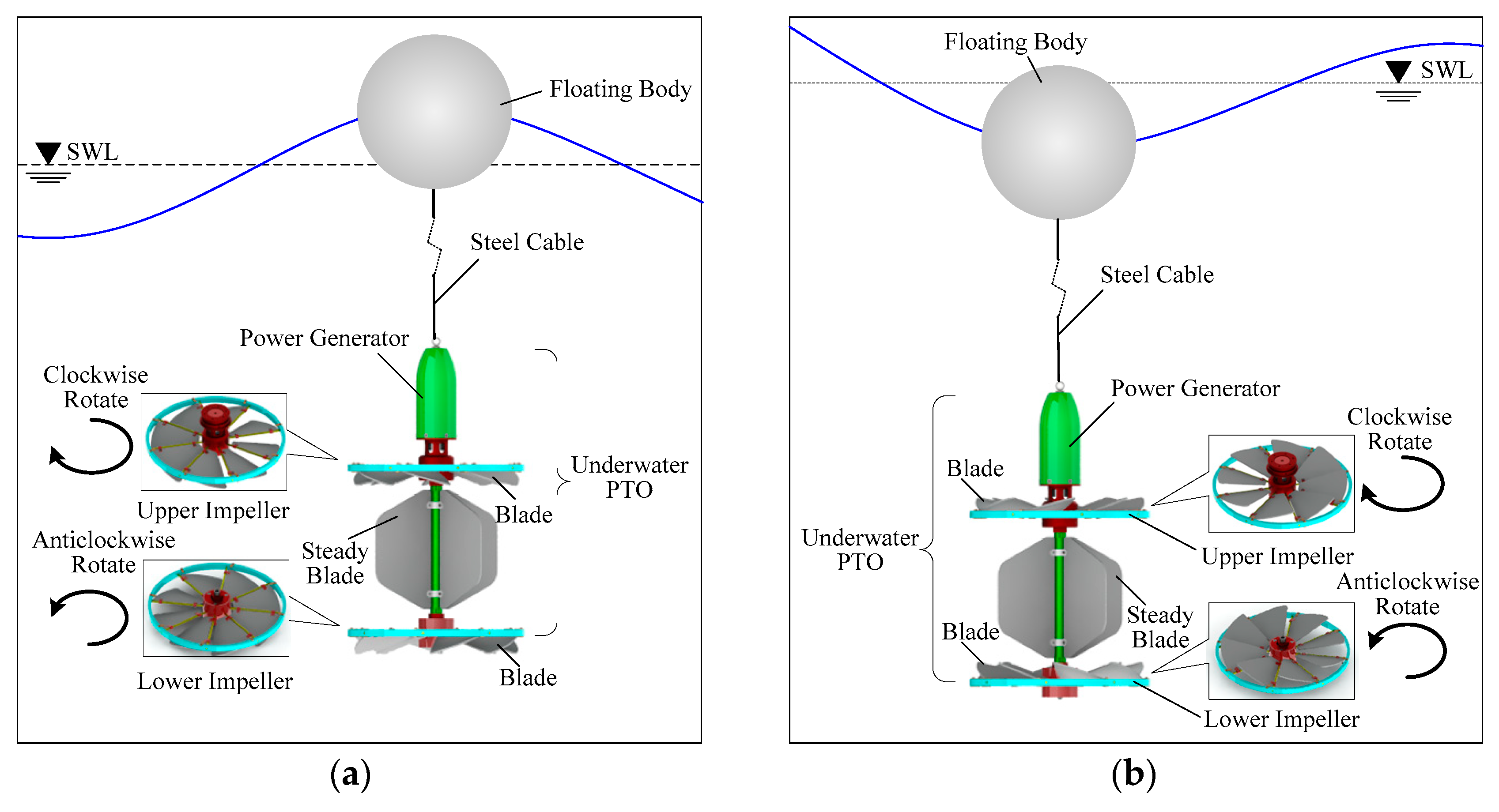
The structure model and working principle of the novel heaving point absorber are feasible. Based on the optimal power supply strategy, the design of the release and recovery mechanism can improve the concealment, release, and recovery rate of the unmanned ocean devices. Under the different directions of water flows, the design of the upper and lower impeller with opposite rotation directions can provide continuous relative rotational motion to the generator during rising and sinking of the Underwater PTO. The design of the locking devices and impellers’ blades with circumference array can achieve the adaptively adjust the blade deflection in the heaving motion and the relative rotation of the impellers. The design of the steady blade can balance the motion of Underwater PTO and makes it not limited by the motion of heaving.
(2)
The energy efficiency of the novel heaving point absorber is greatly affected by the geometric parameters, the wave force, the motion displacement, the motion velocity, and the capture width ratio of the floating body. The constitutive relation of the above parameters of the floating body is constructed. In order to calculate the above parameters, the Froude-Krylov method is used, which effectively overcomes the inaccuracy of the linear models and reduces the time consuming to simulate. The algebraic solution of wave excitation force for the axisymmetric and unaxisymmetric floating body is obtained and validated by the numerical simulation.
(3)
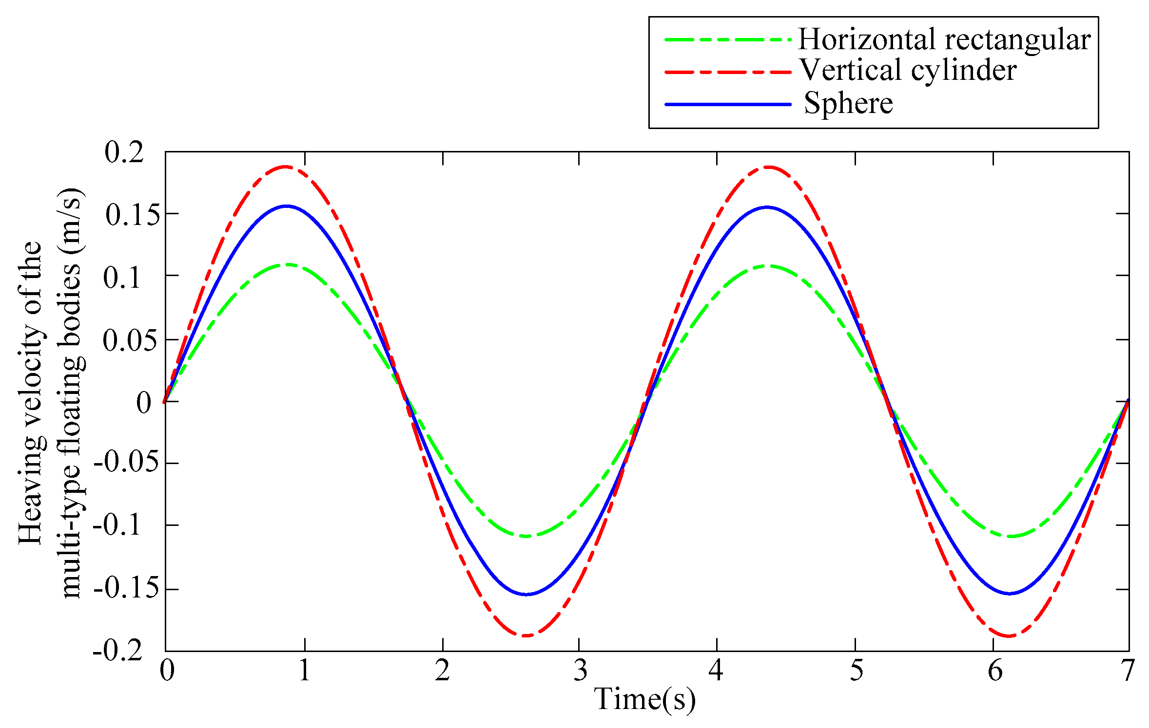
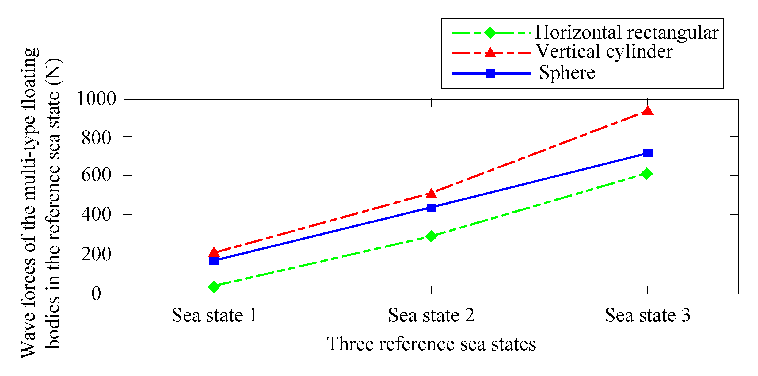
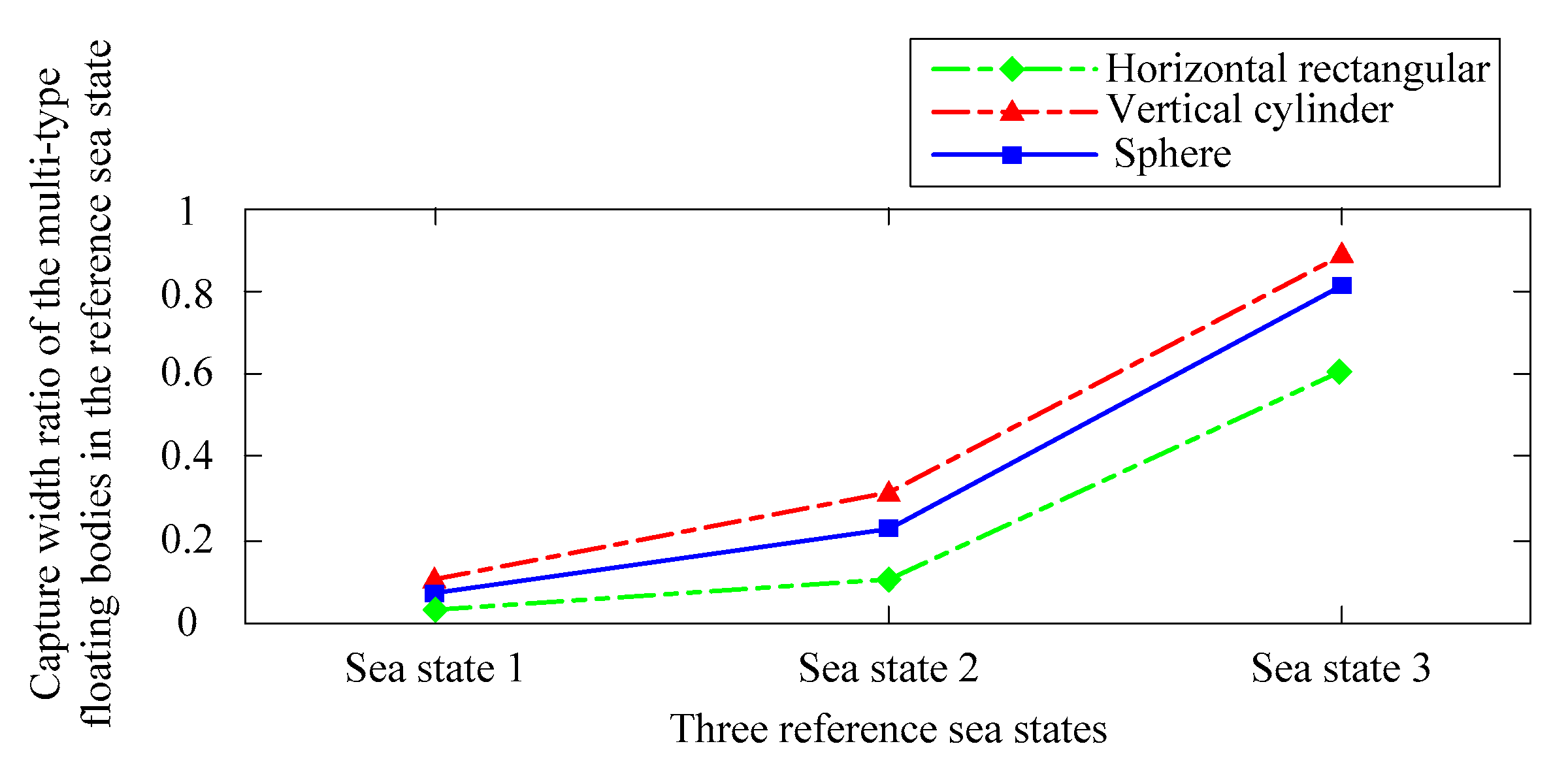
The wave force, heaving velocity, heaving displacement, and capture width ratio of the three floating bodies are compared and analyzed by the numerical simulation. Under the same working condition, mass and mean immersion depth, the type of vertical cylindrical floater’s slopes of the wave force and the steeper amplitude, faster speed of heave motion, larger amplitude of heave motion, better follow wave, larger energy produced, as well as, higher conversion efficiency. Therefore, with the linear regular wave, the cylindrical floater vertically placed on the wave surface is the first optional shape for the novel heaving point absorber and follower is the sphere floater, which can increase the quality of power extracting and the efficient of the WEC system design.
The study that was carried out in this paper focuses on the energy generation efficiency of the novel heaving point absorber for the supply power of the low-power unmanned ocean devices. Moreover, the multi-type floating bodies are optimized base on the Froude-Krylov method. Although a series of numerical analyses above has been conducted in this paper, research on the novel absorber and floating body is still not thorough enough. Therefore, a further step toward is that the verification experiments of wave tank will be done in the power production region for the novel absorber. In addition, the geometric parameters of the vertical cylinder floater will be optimized for increasing the conversion efficiency of the floating body.

Author Contributions

D.C., J.S. and Z.L. conceived the study design; D.C. and C.S. performed the numerical simulations; D.C. analyzed the data and wrote the manuscript; W.W. helped with editing the manuscript.

Funding

This research was funded by National Natural Science Foundation of China (51475465).

Conflicts of Interest

The authors declare no conflict of interest.

Abbreviations

WECWave energy converter
PTOPower take-off
B Heading wave width of the floating body (m)
B PTO Underwater PTO damping coefficient (KNs/m)
B PTO z Underwater PTO damping coefficient in the vertical direction (KNs/m)
C Diffraction correction coefficient (-)
C V Coefficient of wave diffraction in the vertical direction (-)
D Waterline depth of floating body (m)
d Water depth (m)
F D Diffraction force (N)
F R Radiation force (N)
F F K st Static Froude-Krylov force (N)
F F K dy Dynamic Froude-Krylov force (N)
F PTO Underwater PTO damping force (N)
F wave Wave force (N)
F PTO z Underwater PTO damping force in the vertical direction (N)
G Gravity force (N)
g Acceleration of gravity (m/s2)
H Wave height (m)
I Inertia force of attached mass effect (N)
k Wave Number (-)
m Mass of the heaving point absorber (kg)
n Vector normal to the surface (-)
n z Projection of the normal for the wetted surface of the floating body in the vertical direction (-)
P Pressure (Pa)
P st Hydrostatic pressure (Pa)
P dy Dynamic pressure (Pa)
P W E C Average power of the floating body to harvests wave energy (Pa)
P 0 Wave energy of the incident wave within the width of the body (Pa)
Q Viscous damping force (N)
r Wave amplitude (m)
S Submerged surface (m2)
[ T ] Coordinate transformation matrix between local coordinate system and global coordinate system (-)
T Wave period (s)
V W E C Velocity of the floating body (m/s)
( X 0 , Y 0 , Z 0 ) Coordinates of the center of gravity on the floating body in the global coordinate system
( x ¯ , y ¯ , z ¯ ) Coordinates at any point on the floating body in the local coordinate system
X Vertical distance from the reference fluid surface to the body waterline (m)
x Direction of wave propagation in the global coordinate system (-)
x ¯ Direction of wave propagation in the local coordinate system (-)
X Heaving displacement of the body from its hydrostatic equilibrium position (m)
X ˙ Heaving velocity of the floating body (m/s)
X ¨ Heaving acceleration of the body (m/s2)
Y Vertical distance from the reference fluid surface to the fluid surface (m)
Z Vertical distance from the reference fluid surface to any point in the fluid (m)
z Vertical displacement of the floating body in the global coordinate system (m)
z ¯ Vertical displacement of the floating body in the local coordinate system (m)
φ Wave angular frequency (rad/s)
ϕ Potential flow
ϕ I Undisturbed incident flow potential
ϕ D Diffraction potential
ϕ R Radiation potential
ρ Water density (kg/m3)
ω Wave circular frequency (rad/s)
η Capture width ratio (-)

Appendix A

The calculation of wave excitation forces in the vertical direction of multi-type floating bodies.

Appendix A.1. Horizontal Rectangular Floating Body

The wave excitation forces in the vertical direction of the horizontal rectangular floating body is
F ex z = C v s p z d s = C v a x 1 x 1 + b ρ g H 2 c h k ( d λ ( t ) ) c h k d cos ( k x ω t ) d x   = C v a ρ g H 2 c h k ( d λ ( t ) ) c h k d x 1 x 1 + b cos ( k x ω t ) d x   = C v a ρ g H 2 k c h k ( d λ ( t ) ) c h k d [ sin ( k ( x 1 + b ) ω t ) sin ( k x 1 ω t ) ]   = C v a ρ g H k c h k ( d λ ( t ) ) c h k d cos ( k x 1 ω t + k b 2 ) sin k b 2

Appendix A.2. Vertical Cylinder Floating Body

The relationship between any point ( x ¯ , y ¯ , z ¯ ) on the curved surface element d s and the cylinder coordinate [54] ( r , α , z ¯ ) is
{ x ¯ = R cos α y ¯ = R sin α z ¯ = z ¯
Then, the above equation can be written in the global coordinate system is
{ x = R cos α + x 1 + R y = R sin α + y 1 z = z
Let α = π 2 + φ , the dynamic pressure at any point on the cylinder surface at this time in the global coordinate system can be written as:
P dy = ρ g H 2 c h k z c h k d cos ( k ( R cos α + x 1 + R ) ω t )   = ρ g H 2 c h k z c h k d [ cos ( k R sin φ ) cos ( k x 1 + k R ω t )   + sin ( k R sin φ ) sin ( k x 1 + k R ω t ) ]
According to the properties of the Bessel function [55] is as follows:
cos ( k R sin φ ) = J 0 ( k R ) + 2 m = 1 m = J 2 m ( k R ) cos ( 2 m φ ) sin ( k R sin φ ) = 2 m = 1 m = J 2 m 1 ( k R ) sin ( 2 m 1 ) φ }
When m = 1 , and then:
cos ( k R sin φ ) = J 0 ( k R ) + 2 J 2 ( k R ) cos 2 φ sin ( k R sin φ ) = 2 J 1 ( k R ) sin φ }
Combining above equation, we can obtain the following equation:
P dy = ρ g H 2 c h k z c h k d [ ( J 0 ( k R ) + 2 J 2 ( k R ) cos 2 φ ) cos ( k x 1 + k R ω t )   + ( 2 J 1 ( k R ) sin φ ) sin ( k x 1 + k R ω t ) ]
where, J 0 ( k R ) is the first kind zero-order Bessel function, J 1 ( k R ) is the first kind one-order Bessel function, J 2 ( k R ) is the first kind two-order Bessel function. In order to convenient calculation, let J m ( k R ) = J m .
The wave excitation forces in the vertical direction of the vertical cylinder floating body is
F ex z = C v S p z d s = 2 C v d λ ( t ) d 0 π p z R d α d z = 2 C v d λ ( t ) d π 2 π 2 p z R d φ d z   = C v R ρ g H c h k d d λ ( t ) d c h k z d z π 2 π 2 { ( J 0 + 2 J 2 cos 2 φ ) cos ( k x 1 + k R ω t ) + ( 2 J 1 sin φ ) sin ( k x 1 + k R ω t ) } d φ   = C v R ρ g π H J 0 ( k R ) k s h k d s h k ( d λ ( t ) ) c h k d cos ( k x 1 + k R ω t )

Appendix A.3. Sphere Floating Body

The relationship between any point ( x ¯ , y ¯ , z ¯ ) on the curved surface element d s and the spherical coordinate [54] ( r , θ , α ) is
{ x ¯ = R sin θ sin α y ¯ = R sin θ cos α z ¯ = R cos θ
Then, the above equation can be written in the global coordinate system is
{ x = R sin θ sin α + x 1 + R y = R sin θ cos α + y 1 + R z = R cos θ + d + R λ ( t )
Let α = π 2 + φ , the dynamic pressure at any point on the spherical surface at this time in the global coordinate system can be written as:
P dy = ρ g H 2 c h k ( R cos θ + d + R λ ( t ) ) c h k d cos ( k ( R sin θ sin α + x 1 + R ) ω t ) = ρ g H 2 c h k ( R cos θ + d + R λ ( t ) ) c h k d { cos ( k R sin θ sin φ ) cos ( k x 1 + k R ω t ) + sin ( k R sin θ sin φ ) sin ( k x 1 + k R ω t ) }
According to the properties of the Bessel function [55] is as follows:
cos ( k R sin θ sin φ ) = J 0 ( k R sin θ ) + 2 m = 1 m = J 2 m ( k R sin θ ) cos ( 2 m φ )     sin ( k R sin θ sin φ ) = 2 m = 1 m = J 2 m 1 ( k R sin θ ) sin ( 2 m 1 ) φ }
When m = 1 , and then:
cos ( k R sin θ sin φ ) = J 0 ( k R sin θ ) + 2 J 2 ( k R sin θ ) cos 2 φ   sin ( k R sin θ sin φ ) = 2 J 1 ( k R sin θ ) sin φ }
Combining above equation, we can obtain the following equation
P dy = ρ g H 2 c h k ( R cos θ + d + R λ ( t ) ) c h k d { ( J 0 ( k R sin θ ) + 2 J 2 ( k R sin θ ) cos 2 φ ) cos ( k x 1 + k R ω t ) + ( 2 J 1 ( k R sin θ ) sin φ ) sin ( k x 1 + k R ω t ) }
where, J 0 ( k R sin θ ) is the first kind zero-order Bessel function, J 1 ( k R sin θ ) is the first kind one-order Bessel function, J 2 ( k R sin θ ) is the first kind two-order Bessel function. In order to convenient calculation, let J m ( k R sin θ ) = J m .
The wave excitation forces in the vertical direction of the sphere floating body is
F w z = 2 C v π arccos ( R λ ( t ) R ) π 0 π p z cos θ R 2 sin θ d α d θ   = C v R 2 ρ g H c h k d π arccos ( R λ ( t ) R ) π π 2 π 2 c h k ( R cos θ + d + R λ ( t ) )   { ( J 0 + 2 J 2 cos 2 φ ) cos ( k x 1 + k R ω t ) + 2 J 1 sin φ sin ( k x 1 + k R ω t ) } cos θ sin θ d φ d θ   = C v π R 2 ρ g H c h k d ( I 1 ( k R ) I 2 ( k R ) ) cos ( k x 1 + k R ω t )
where, I 1 ( k R ) = π arccos ( R λ ( t ) R ) π c h ( k R cos θ ) c h k ( d + R λ ( t ) ) J 0 ( k R sin θ ) cos θ sin θ d θ , I 2 ( k R ) = π arccos ( R λ ( t ) R ) π s h ( k R cos θ ) s h k ( d + R λ ( t ) ) J 0 ( k R sin θ ) cos θ sin θ d θ .

References

  1. Bertaska, I.R.; Ellenrieder, K.D.V. Experimental evaluation of supervisory switching control for unmanned surface vehicles. IEEE J. Ocean. Eng. 2018, 99, 1–22. [Google Scholar] [CrossRef]
  2. Mousazadeh, H.; Jafarbiglu, H.; Abdolmaleki, H.; Omrani, E.; Monhaseri, F.; Abdollahzadeh, M.R.; Mohammadi-Aghdam, A.; Kiapei, A.; Salmani-Zakaria, Y.; Makhsoos, A. Developing a navigation, guidance and obstacle avoidance algorithm for an unmanned surface vehicle (USV) by algorithms fusion. Ocean Eng. 2018, 159, 56–65. [Google Scholar] [CrossRef]
  3. Zoss, B.M.; Mateo, D.; Kuan, Y.K.; Tokić, G.; Chamanbaz, M.; Goh, L.; Vallegra, F.; Bouffanais, R.; Yue, D.K. Distributed system of autonomous buoys for scalable deployment and monitoring of large waterbodies. Auton. Robots 2018, 11, 1–21. [Google Scholar] [CrossRef]
  4. Banazadeh, A.; Seif, M.S.; Khodaei, M.J.; Rezaie, M. Identification of the equivalent linear dynamics and controller design for an unmanned underwater vehicle. Ocean Eng. 2017, 139, 152–168. [Google Scholar]
  5. Venkatesan, R.; Sannasiraj, S.A.; Ramanamurthy, M.V.; Senthilkumar, P.; Dhinesh, G. Development and performance validation of a cylindrical buoy for deep-ocean tsunami monitoring. IEEE J. Ocean. Eng. 2018, 99, 1–9. [Google Scholar] [CrossRef]
  6. Danovaro, R.; Aguzzi, J.; Fanelli, E.; Billett, D.; Gjerde, K.; Jamieson, A.; Ramirez-Llodra, E.; Smith, C.R.; Snelgrove, P.V.R.; Thomsen, L.; et al. An ecosystem-based deep-ocean strategy. Science 2017, 355, 452–454. [Google Scholar] [CrossRef] [PubMed]
  7. Sun, C.; Luo, Z.; Shang, J.; Lu, Z.; Zhu, Y.; Wu, G. Design and Numerical Analysis of a Novel Counter-Rotating Self-Adaptable Wave Energy Converter Based on CFD Technology. Energies 2018, 11, 694. [Google Scholar] [CrossRef]
  8. Mendez, A.; Leo, T.J.; Herreros, M.A. Current state of technology of fuel cell power systems for autonomous underwater vehicles. Energies 2014, 7, 4676–4693. [Google Scholar] [CrossRef]
  9. Wang, X.; Shang, J.; Luo, Z.; Tang, L.; Zhang, X.; Li, J. Reviews of power systems and environmental energy conversion for unmanned underwater vehicles. Renew. Sustain. Energy Rev. 2012, 16, 1958–1970. [Google Scholar] [CrossRef]
  10. Dhanak, M.R.; Xiros, N.I. Handbook of Ocean Engineering; Springer: New York, NY, USA, 2016. [Google Scholar]
  11. Astariz, S.; Iglesias, G. The economics of wave energy: A review. Renew. Sustain. Energy Rev. 2015, 45, 397–408. [Google Scholar] [CrossRef]
  12. Cruz, J. Ocean Wave Energy; Springer: Berlin, Germany, 2008; Volume 144, pp. 2451–2460. [Google Scholar]
  13. Gunn, K.; Stock-Williams, C. Quantifying the global wave power resource. Renew. Energy 2012, 44, 296–304. [Google Scholar] [CrossRef]
  14. Saprykina, Y.; Kuznetsov, S. Analysis of the Variability of Wave Energy Due to Climate Changes on the Example of the Black Sea. Energies 2018, 11, 2020. [Google Scholar] [CrossRef]
  15. Clément, A.; McCullen, P.; Falcão, A.; Gardner, F.; Hammarlund, K.; Lemonis, G.; Lewis, T.; Nielsen, K.; Petroncini, S.; Pontes, M.-T.; et al. Wave energy in Europe: Current status and perspectives. Renew. Sustain. Energy Rev. 2002, 6, 405–431. [Google Scholar] [CrossRef]
  16. Salter, S.H. Wave power. Nature 1974, 249, 720–724. [Google Scholar] [CrossRef]
  17. O’Hagan, A.M.; Huertas, C.; O’Callaghan, J.; Greaves, D. Wave energy in Europe: Views on experiences and progress to date. Int. J. Mar. Energy 2016, 14, 180–197. [Google Scholar] [CrossRef]
  18. Rusu, E.; Onea, F. Estimation of the wave energy conversion efficiency in the Atlantic ocean close to the European islands. Renew. Energy 2016, 85, 687–703. [Google Scholar] [CrossRef]
  19. Kalogeri, C.; Galanis, G.; Spyrou, C.; Diamantis, D.; Baladima, F.; Koukoula, M.; Kallos, G. Assessing the European offshore wind and wave energy resource for combined exploitation. Renew. Energy 2017, 101, 244–264. [Google Scholar] [CrossRef]
  20. Stegman, A.; Andres, A.D.; Jeffrey, H.; Johanning, L.; Bradley, S. Exploring marine energy potential in the UK using a whole systems modeling approach. Energies 2017, 10, 1251. [Google Scholar] [CrossRef]
  21. Aderinto, T.; Li, H. Ocean wave energy converters: Status and challenges. Energies 2018, 11, 1250. [Google Scholar] [CrossRef]
  22. Chen, B.; Bruce, T.; Greated, C.A.; Kang, H. Dynamic behavior of a wave power buoy with interior on-board linear generator. Ocean Eng. 2017, 129, 374–381. [Google Scholar] [CrossRef]
  23. Weber, J.; Costello, R.; Mouwen, F.; Ringwood, J.; Thomas, G. Techno-economic WEC system optimization methodology applied to Wavebob system definition. In Proceedings of the 3th International Conference on Ocean Energy, Bilbao, Spain, 6–8 October 2010; Volume 10, p. 6. [Google Scholar]
  24. Chatzigiannakou, M.A.; Dolguntseva, I.; Leijon, M. Offshore deployments of wave energy converters by Seabased industry AB. J. Mar. Sci. Eng. 2017, 5, 15. [Google Scholar] [CrossRef]
  25. Fred Olsen’s Lifesaver Buoy. Available online: http://boltseapower.com/company/ (accessed on 25 November 2018).
  26. Moskvitch, K. News briefing: In num6ers: CETO 6 Carnegie wave energy. Eng. Technol. 2016, 11, 12–13. [Google Scholar] [CrossRef]
  27. Black, J.L.; Mei, C.C.; Bray, C.G. Radiation and Scattering of Water Waves by Rigid Bodies. J. Fluid Mech. 1971, 46, 151–164. [Google Scholar] [CrossRef]
  28. Mohapatra, S.C.; Guedes Soares, C. Wave forces on a floating structure over flat bottom based on Boussinesq formulation. In Renewable Energies Offshore; Taylor & Francis Group: London, UK, 2015; pp. 335–342. [Google Scholar]
  29. Rodriguez, M.; Spinneken, J.; Swan, C. Nonlinear loading of a two-dimensional heaving box. J. Fluids Struct. 2016, 60, 80–96. [Google Scholar] [CrossRef] [Green Version]
  30. Islam, H.; Mohapatra, S.C.; Guedes, S.C. Comparisons of CFD, experimental and analytical simulations of a heaving box-type floating structure. In Progress in Maritime Technology and Engineering; Taylor & Francis Group: London, UK, 2018; Volume 5, pp. 633–639. [Google Scholar]
  31. Yeung, R.W. Added Mass and Damping of a Vertical Cylinder in Finite Depth Waters. Appl. Ocean Res. 1981, 3, 119–133. [Google Scholar] [CrossRef]
  32. Sabuncu, T.; Calisal, S. Hydrodynamic Coefficients for Vertical Circular Cylinder at Finite Depth. Ocean Eng. 1981, 8, 25–63. [Google Scholar] [CrossRef]
  33. Calisal, S.; Sabuncu, T. Hydrodynamic Coefficients for Vertical Composite Cylinders. Ocean Eng. 1984, 11, 529–542. [Google Scholar] [CrossRef]
  34. Mansour, A.M.; WiUliam, A.N.; Wang, K.H. The diffraction of linear waves by a uniform vertical cylinder with cosine-type radial perturbations. Type Radial Perturbations. Ocean Eng. 2002, 29, 239–259. [Google Scholar] [CrossRef]
  35. Bhatta, D.; Rahman, M. On Scattering and Radiation Problem for a Cylinder in Water of Finite Depth. Int. J. Eng. Sci. 2003, 41, 931–967. [Google Scholar] [CrossRef]
  36. Kim, W.D. On the Harmonic Oscillations of a Rigid Body on a Free Surface. J. Fluid Mech. 1965, 21, 427–451. [Google Scholar] [CrossRef]
  37. Bihs, H.; Kamata, A.; Lu, Z.J.; Arntsen, I.A. Simulation of Floating Bodies using a Combined Immersed Boundary with the Level Set Method in REEF3D. In Proceedings of the VII International Conference on Computational Methods in Marine Engineering, Nantes, Frances, 15–17 June 2017. [Google Scholar]
  38. Koh, H.J.; Cho, I.H. Heave motion response of a circular cylinder with the dual damping plates. Ocean Eng. 2016, 125, 95–102. [Google Scholar] [CrossRef]
  39. Wang, S. The Hydrodynamic Forces and Pressure Distributions for an Oscillating Sphere in a Fluid of Finite Depth; M.I.T. Department of Naval Architecture and Marine Engineering: Cambridge, MA, USA, 1966. [Google Scholar]
  40. Finnegan, W.; Meere, M.; Goggins, J. The wave excitation forces on a truncated vertical cylinder in water of infinite depth. J. Fluids Struct. 2013, 40, 201–213. [Google Scholar] [CrossRef] [Green Version]
  41. Ghadimi, P.; Bandari, H.P.; Rostami, A.B. Determination of the Heave and Pitch Motions of a Floating Cylinder by of the Effects of Geometric Parameters on its Dynamics in Regular Waves. Int. J. Appl. Math. Res. 2012, 1, 611–633. [Google Scholar] [CrossRef]
  42. Giorgi, G.; Ringwood, J.V. Computationally efficient nonlinear froude–krylov force calculations for heaving axisymmetric wave energy point absorbers. J. Ocean Eng. Mar. Energy 2017, 3, 21–33. [Google Scholar] [CrossRef]
  43. Merigaud, A.; Gilloteaux, J.C.; Ringwood, J.V. A Nonlinear Extension for Linear Boundary Element Methods in Wave Energy Device Modeling. In Proceedings of the International Conference on Ocean, Offshore and Arctic Engineering, Rio de Janeiro, Brazil, 1–6 July 2012. [Google Scholar]
  44. Penalba, M.; Mérigaud, A.; Gilloteaux, J.C.; Ringwood, J.V. Influence of nonlinear Froude Krylov forces on the performance of two wave energy points absorbers. J. Ocean Eng. Mar. Energy 2017, 3, 209–220. [Google Scholar] [CrossRef]
  45. Rodrigues, J.M.; Soares, C.G. Froude-krylov forces from exact pressure integrations on adaptive panel meshes in a time domain partially nonlinear model for ship motions. Ocean Eng. 2017, 139, 169–183. [Google Scholar] [CrossRef]
  46. Falnes, J.; Perlin, M. Ocean waves and oscillating systems: Linear interactions including wave-energy extraction. Appl. Mech. Rev. 2003, 56, 286. [Google Scholar] [CrossRef]
  47. Falnes, J. Ocean Waves and Oscillating Systems; Cambridge University Press: Cambridge, UK, 2002. [Google Scholar]
  48. Clement, A.; Ferrant, P. Superharmonic Waves Generated by the Large Amplitude Heaving Motion of a Submerged Body. In Nonlinear Water Waves; Springer: Berlin/Heidelberg, Germany, 1988; pp. 423–433. [Google Scholar]
  49. Yu, H.; Zhang, Y.; Chen, W. Effect of Power Take-off System on the Capture Width Ratio of a Novel Wave Energy Converter. In Proceedings of the Asian Wave & Tidal Energy Conference, Singapore, 24–28 October 2016. [Google Scholar]
  50. Chen, T.X.; Wu, B.J.; Li, M. Flume experiment study on capture width ratio of a new backward bent duct buoy with a pentagon buoyancy cabin. Ocean Eng. 2017, 141, 12–17. [Google Scholar] [CrossRef]
  51. Herbich, J.B. Offshore Pipeline Design Elements; M. Dekker: New York, NY, USA, 1981. [Google Scholar]
  52. Standing, R.G. Use of potential theory in evaluating wave forces on offshore structures. In Power from Sea Waves, Conference Institute of Mathematics and its Applications; Academic Press: London, UK, 1980; Volume 1, pp. 175–212. [Google Scholar]
  53. Garrison, C.J.; Rao, V.S. Interaction of waves with submerged objects. J. Waterw. Harb. Coast. Eng Div. 1971, 97, 259–277. [Google Scholar]
  54. Korn, G.A.; Korn, T.M. Mathematical Handbook for Scientists and Engineers; McGraw-Hill: New York, NY, USA, 1968. [Google Scholar]
  55. Watson, G.N. Theory of Bessel Functions; Cambridge University Press: Cambridge, UK, 1962. [Google Scholar]
Figure 1. The working scene of the novel heaving wave energy point absorber.
Energies 11 03282 g001
Figure 2. The system configuration and working principle of the novel heaving point absorber. (a) Rising state; and, (b) Sinking state.
Energies 11 03282 g002
Figure 3. The coordinates and force analysis of floating body.
Energies 11 03282 g003
Figure 4. The wave force of the multi-type floating bodies ( H = 0.3 m, T = 3.5 s).
Energies 11 03282 g004
Figure 5. The heaving velocity of the multi-type floating bodies ( H = 0.3 m, T = 3.5 s).
Energies 11 03282 g005
Figure 6. The heaving displacement of the multi-type floating bodies ( H = 0.3 m, T = 3.5 s).
Energies 11 03282 g006
Figure 7. The capture width ratio of the multi-type floating bodies ( H = 0.3 m, T = 3.5 s).
Energies 11 03282 g007
Figure 8. The wave forces of the multi-type floating bodies in the reference sea state.
Energies 11 03282 g008
Figure 9. The heaving velocity of the multi-type floating bodies in the reference sea state.
Energies 11 03282 g009
Figure 10. The heaving displacement of the multi-type floating bodies in the reference sea state.
Energies 11 03282 g010
Figure 11. The capture width ratio of the multi-type floating bodies in the reference sea state.
Energies 11 03282 g011
Table 1. The algebraic solutions of the wave excitation force in the vertical direction of multi-type floating bodies.
The Geometry Shapes of Floating BodiesThe Coordinates of Floating BodiesThe Parameters of Profiles and CoordinatesThe Wave Excitation Force in the Vertical Direction of Floating Bodies
Unaxisy-mmetricHorizontal rectangular Energies 11 03282 i001 a is the length, b is the length along the wave direction, c is the height, λ ( t ) is the immer-sion depth in the time of t . F ex z = C V a ρ g H k c h k ( d λ ( t ) ) c h k d cos ( k x 1 ω t + k b 2 ) sin k b 2
(See Appendix A for calculation details.)
Axisym-metricVertical cylinder Energies 11 03282 i002 R is the radius, l is the heig-
ht, λ ( t ) is the immersion de-
pth in the time of t , the cylin-
der equation is x ¯ 2 + y ¯ 2 = R 2 ,the cylinder coordinate is ( r , α , z ¯ ) , z ¯ = c o n s t a n t , α = c o n s t a n t , S is wetted surface,
S : r = R , 0 α 2 π 0 z ¯ λ ( t ) ,
then, d S = R d α d z ¯ .
F ex z = C V R ρ g π H J 0 ( k R ) k s h k d s h k ( d λ ( t ) ) c h k d cos ( k x 1 + k R ω t )
(See Appendix A for calculation details.)
Sphere Energies 11 03282 i003 R is the radius, λ ( t ) is the immersion depth in the time of t , the spherical equation is x ¯ 2 + y ¯ 2 + z ¯ 2 = R 2 , the sphere-
cal coordinate is ( r , θ , α ) , θ = c o n s t a n t , α = c o n s t a n t ,
S is wetted surface,
S : r = R , π arccos ( R λ ( t ) R ) θ π , 0 α 2 π
then, d S = R 2 sin θ d θ d α
F ex z = C V π R 2 ρ g H c h k d ( I 1 ( k R ) I 2 ( k R ) ) cos ( k x 1 + k R ω t )
I 1 ( k R ) = π arccos ( R λ ( t ) R ) π c h ( k R cos θ ) c h k ( d + R λ ( t ) ) J 0 ( k R sin θ ) cos θ sin θ d θ
I 2 ( k R ) = π arccos ( R λ ( t ) R ) π s h ( k R cos θ ) s h k ( d + R λ ( t ) ) J 0 ( k R sin θ ) cos θ sin θ d θ
(See Appendix A for calculation details.)

