1. Introduction
Drive-trains of electric vehicles operate more efficiently compared to those of conventionally motorized vehicles. Therefore electric vehicles are a promising opportunity to reduce local carbon dioxide emissions and to increase the vehicle’s overall energy efficiency. Furthermore, modern electric drive-trains provide a variety of new features besides propulsion. Consequently, both the power train and the wheel suspension systems can be rethought for integration of these functions. Especially the development and use of wheel-individual drives offer a considerable potential in this regard. For instance, a power-assisted steering effect can be achieved by wheel-individual drives. Different torques applied to the left and right front wheels can significantly influence the driver’s steering torque. Compared to conventional power-assisted steering systems, less actuators fulfil the same functions and offer potential for energy saving.
This contribution serves to analyse and evaluate the energy demand of a vehicle equipped with a power steering system using wheel-individual drives compared to vehicles equipped with conventional power steering systems. In
Section 2 and
Section 3, the state of research and the concept of power steering using wheel-individual drives are introduced. In
Section 4, we propose a vehicle model and driving manoeuvres for simulation and discuss the results. The summary and conclusion are given in
Section 5 and
Section 6.
2. State of Research
Modern drive-train concepts allow a wheel-individual drive torque control to influence the lateral dynamics of vehicles by longitudinal dynamics. In the following, publications are introduced that represent the state of research in assisted steering and steer-by-wire concepts by using longitudinal forces.
A steering system called “driving force power steering” (DFPS) presented by Li-Qiang et al. in [
1] reduces the driver’s steering torque in a vehicle with a positive scrub radius and wheel hub drives. Polmans et al. [
2] study a redundant steering system by wheel-individual driving of the front wheels by means of wheel hub motors. In this case, the front wheels are steered exclusively by the power of the drive motors. Wang et al. in [
3] study a similar steering system based on wheel hub motors and a chassis also with a scrub radius of 70 mm. The presented “differential drive assisted steering” system (DDAS) is able to reduce the driver’s steering torque by up to 10 Nm. Gauger et al. [
4] present a similar approach using wheel-selective braking. It is possible to effectively influence the steering torque and, with limitations, to actuate the steering system. Dominguez et al. [
5] improve this system by using a customized chassis with a larger scrub radius. Wu et al. [
6] present a vehicle equipped with wheel hub motors and a very large scrub radius of 240 mm of the front axle, which can reduce the driver’s steering torque to 0 Nm. As chassis parameters of this type could cause unintended steering torque on road surfaces with different friction coefficients, the use of a traction control system is recommended.
These studies clearly show that suitable chassis design and specific actuation of longitudinal forces can achieve steering power assistance and, to a limited extent, even independent steering actuation. However, the use of wheel hub motors or conventional friction brakes to generate longitudinal forces entails the considerable disadvantage of the influences of driving and braking forces on the steering system being identical and inseparable.
The authors therefore present in [
7] a chassis and steering system concept based on chassis mounted wheel-individual drives. Thus, the driving forces generate a steering torque via the disturbance force lever arm instead of the scrub radius. Hence, braking and driving forces can be separated, which offers clear advantages especially with regard to other driver assistance systems, such as Anti-lock Braking System (ABS) or Electronic Stability Program (ESP).
3. Power Steering System Driven by Wheel-Individual Drives
The function of power-assisted steering can be integrated into the drive-train by using suitably controlled wheel-individual drives on the front axle and a suitable chassis geometry. The objective of development in the research project “Energy-optimized Intelligent Power Steering System for Electric Vehicles—e2-Lenk” is to completely substitute the conventional power-assisted steering system. The project is handled jointly by Schaeffler and the Karlsruhe Institute of Technology.
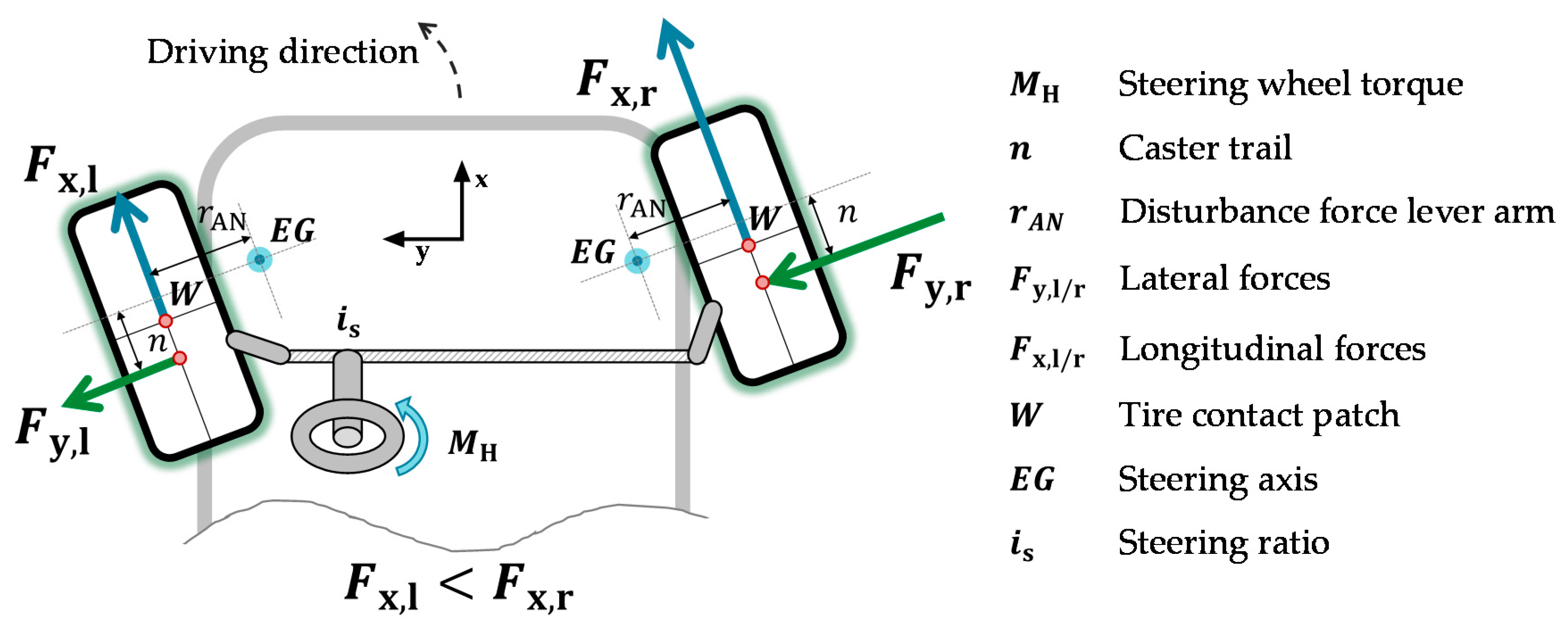
The basic idea of e
2-Lenk is as follows: Different torques applied to the left and right wheels can influence the driver’s steering torque in the sense of power-assisted steering. This is achieved via the driving forces
acting on the wheel contact patch W, which, together with the acting lever arms
of the wheel suspension, result in a steering torque around the steering axis
EG. The produced steering torque counteracts the self-centering effect caused by the lateral forces
and the caster trail
n (see
Figure 1).
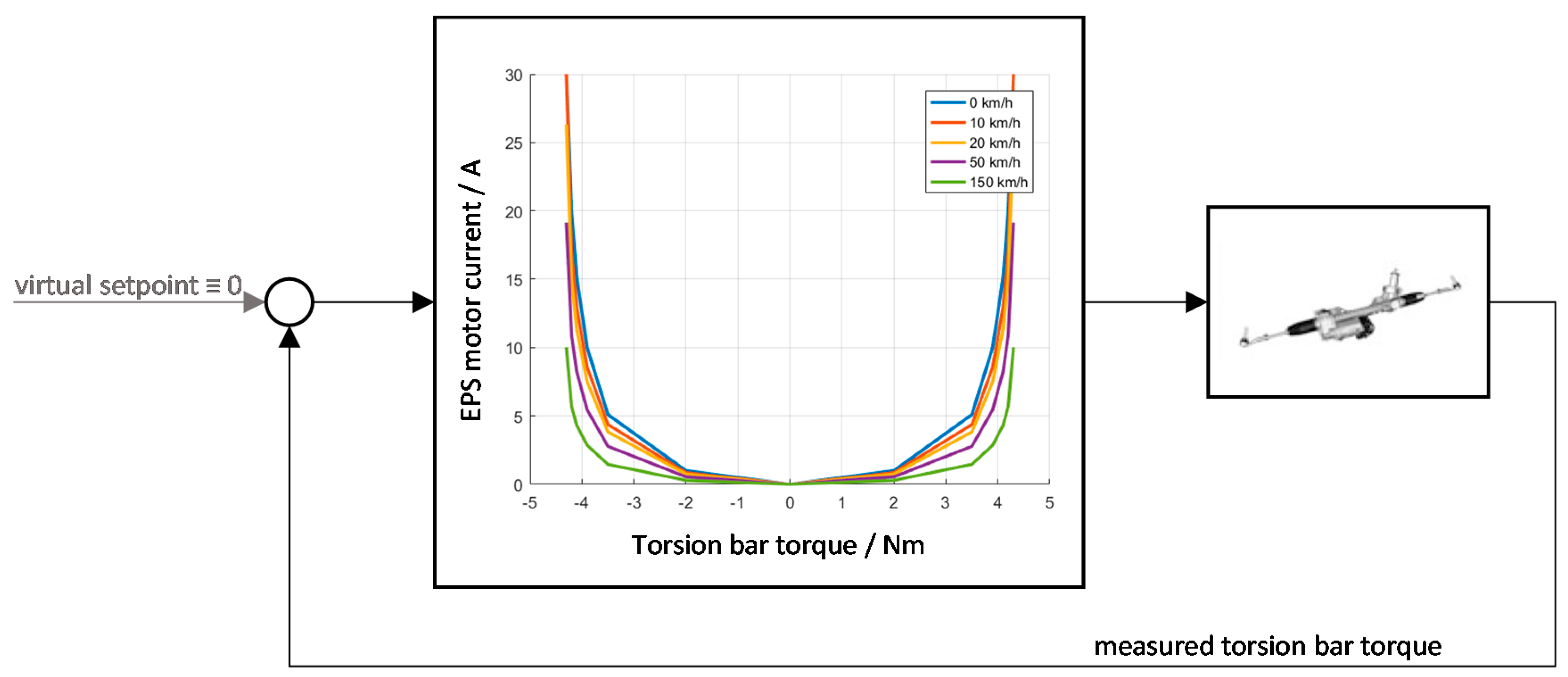
Regarding to Harrer and Pfeffer [
8], all classical control plans for conventional power steering systems have in common that they emulate the functions of a hydraulic power steering system: a suitable assistance torque is applied by the power steering system as a function of the driver’s steering wheel torque respectively the torsion bar torque. This structure can be interpreted as a P control algorithm with a virtual set point of 0 Nm and variable gain (see
Figure 2). The steering feel is the resulting residual deviation of the P controller that can be adjusted by the power assistance characteristic curves. Classical characteristic curves increase the P gain factor with rising deviation. Thus, a rising torsion bar torque leads to a rising assistance torque which produces a degressive steering wheel torque over lateral acceleration.
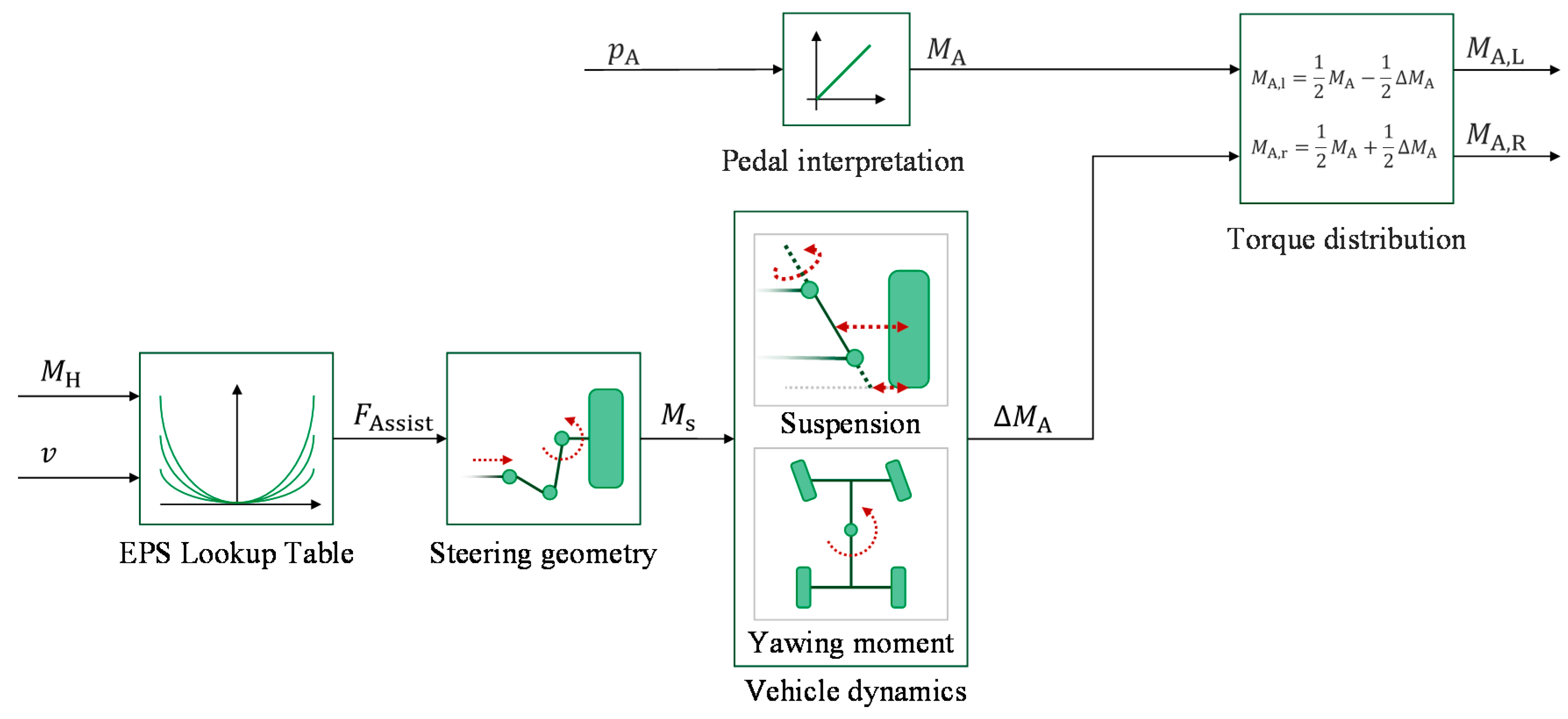
The conventional power steering system and the steering assistance by means of wheel-individual drives have to offer the same steering support, in order to make an energetic comparison meaningful. For influencing the driver’s steering torque as in a conventional power-assisted steering system, we also use the classical kind of control system to produce the assistance torque by actuating the driving motors (see
Figure 3). As a function of the steering wheel torque
and the vehicle speed
the assistance characteristic curves based on [
9] supply the required assistance force
to suitably influence the steering wheel torque. The same curves of assistance characteristics are used in both systems (EPS lookup table), in order to ensure that the steering assistance of conventional systems and our novel process by using wheel-individual drives show a high level of agreement with respect to assistance. However, this requires the steering kinematics to be determined, from the conventional EPS motor to the connection of the rack up to the steering torque generated at the steering axle. The torque around the steering axle
generated by the EPS motor is converted to the required differential torques
at the wheels, in consideration of chassis parameters, chassis kinematics and effects of driving dynamics.
The driver’s desired acceleration is detected via the accelerator pedal position and is distributed equally to the drive torque of the left and right wheel. To take the steering assistance torque into account without influencing the vehicle’s acceleration, the required torque difference is equally superimposed with inverse effective direction.
4. Analysis of Energy Demand
4.1. Simulation Environment
The energetic analysis performed in this study uses the vehicle simulation software CARMAKER
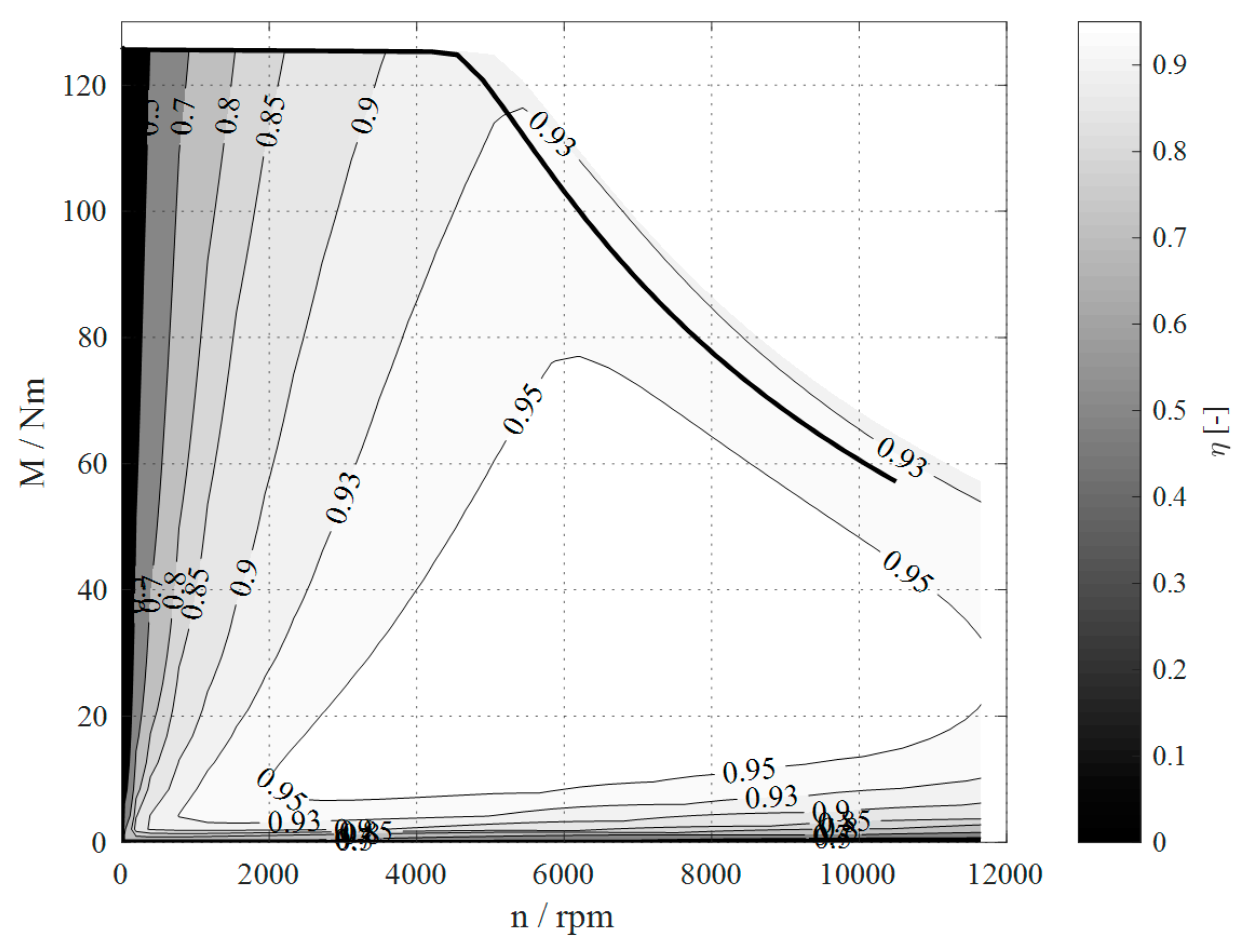
® 5.1.3 by IPG Automotive GmbH (Karlsruhe, Germany). The standard vehicle (DemoCar) represents a compact-class car equipped with an internal combustion engine. We adapted the model to represent two wheel-individual electric drives of 65 kW, 125 Nm and a gear ratio of
each at the steered front axle. The simulation of electric drives uses a map of efficiency curves obtained by electric drive simulation (see
Figure 4).
We use double wishbone suspensions with a disturbance force lever arm of
, a caster trail of
and a scrub radius of
. The weight of a power-assisted steering system, such as BOSCH Servolectric
® EPSapa [
10], not including the steering output systems (tie rods, bellows, outer joints) is 12–15 kg, depending on engineering. This means a difference of approximately 7 kg (motor including control unit) in comparison to a steering system without assistance actuators [
11]. This is taken into account appropriately in the total mass of the vehicle of
and
, respectively.
4.2. Test Procedure and Driving Manoeuvres
Four different types of test procedures are used to analyse the assistance function and energy demand of the steering assistance systems. We use the standardized driving manoeuvres quasi-steady-state circular driving (as per [
12]), double lane change (as per [
13]) and a slalom course (based on ISO 13674-1 [
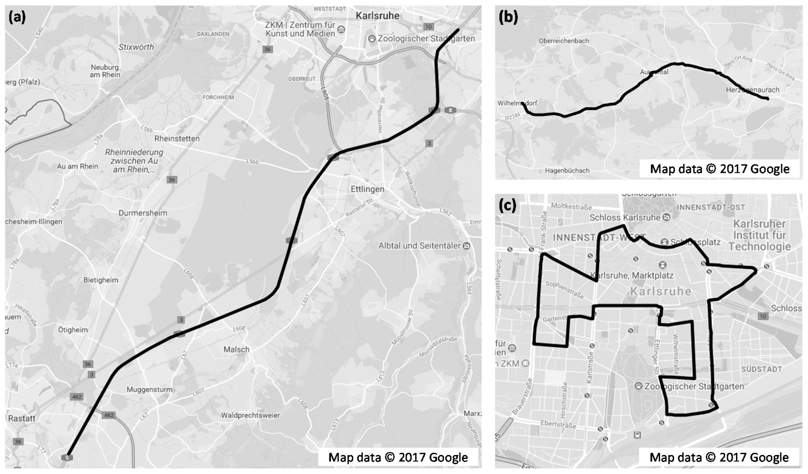
14] to cover driving situations encountered frequently and relevant to vehicle design and one self-designed procedure (realistic driving cycles) to obtain realistic information about the energetic effects of the novel power steering system. The procedure to obtain realistic information consists of three different realistic driving cycles on basis of city and out-of-city trips in Germany (see
Figure 5). Driving cycle (a) models a motorway trip near Karlsruhe of approximately 25.5 km. Driving cycle (b) models a highway trip near Herzogenaurach of approximately 12.5 km. Driving cycle (c) finally represents a trip through the city of Karlsruhe of approximately 13 km length.
The maximum driving speed is 130 km/h on motorways, 100 km/h on highways, and 50 km/h in cities. The driving cycles are simulated with different parameters of the virtual driver. The maximum permissible lateral acceleration of the driver is varied in ten steps between and . Thus, a style of driving ranging between defensive and dynamic is modelled. Hence, a broad spectrum of driving situations can be covered.
4.3. Results and Discussion
4.3.1. Quasi-Steady-State Circular Operation
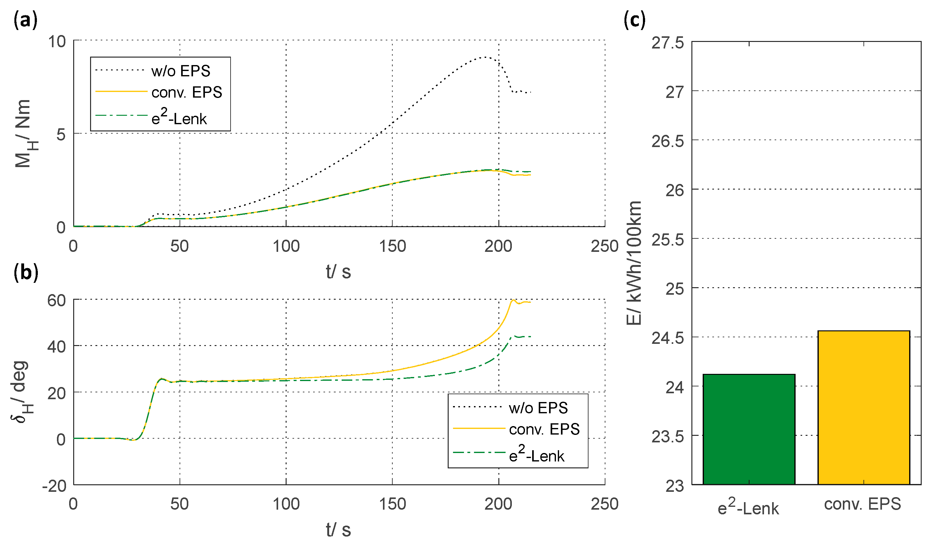
Quasi-steady-state circular operation clearly shows the function of power steering systems. The steering wheel torque required to drive through the circle is reduced (see
Figure 6a). Both the conventional power-assisted steering system and the e
2-Lenk system reduce the steering wheel torque, compared to the vehicle without power assisted steering, by up to a factor of three.
Considering the steering wheel angle, the influence of the occurring torque vectoring effect becomes evident (see
Figure 6b). The e
2-Lenk process reduces the steering wheel angle compared to the conventional power steering system and to a vehicle without any assistance functionality by reducing the slip angle. The steering wheel angle remains almost constant despite increasing lateral acceleration.
Steady-state circular operation represents a sophisticated driving manoeuvre for the e
2-Lenk approach regarding energy demand. As very little longitudinal acceleration of
is necessary to maintain the slight increase in lateral acceleration
, the mean driving torque of the vehicle is very low. Roemer et al. [
15] showed that with conventional chassis parameters the inner wheel drive has to use recuperation mode to achieve the required differential torque at lateral accelerations of
.
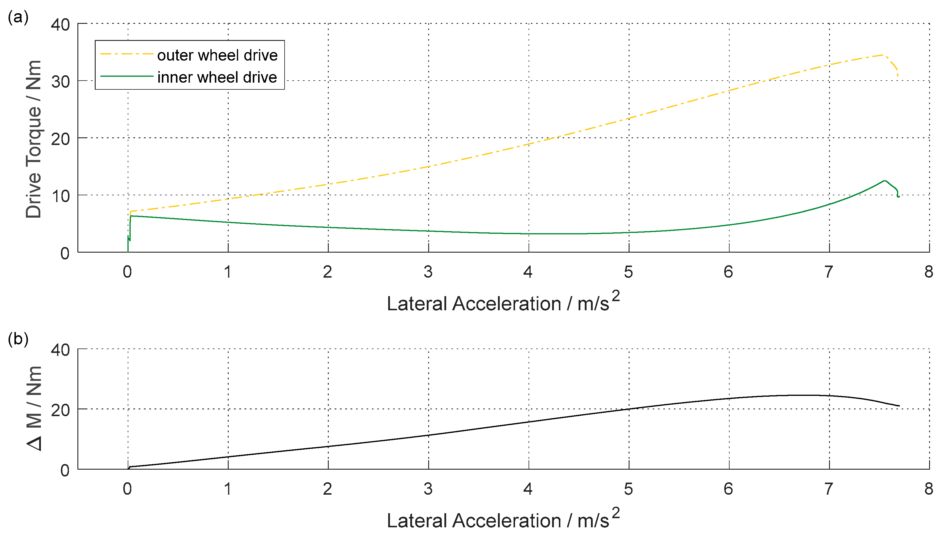
This problem is solved by the use of the new suspension with a larger disturbance force lever arm. Thus, the inner wheel drive torque is positive all the time (see
Figure 7a) and the energy demand is reduced by
in comparison to a conventional vehicle with EPS (see
Figure 6c).
The self-aligning torque and thus the steering wheel torque initially increases linearly over lateral acceleration. However, the self-aligning torque decreases at a lateral acceleration of approximately
. This effect is based on the reduction of the pneumatic trail, which reduces the lever arm, with which the lateral forces generate the self-aligning torque. At this point, the torque difference between both drive torques is reduced, in order not to get too high steering assistance (see
Figure 7b). Thus, the steering assistance of both systems is equivalent. The steering wheel torque of e
2-Lenk and of the conventional power steering system differ by
as a root mean square value, the maximum deviation is
. The largest deviation occurs towards the end of circular driving because of reaching the vehicle’s limits at a lateral acceleration of
.
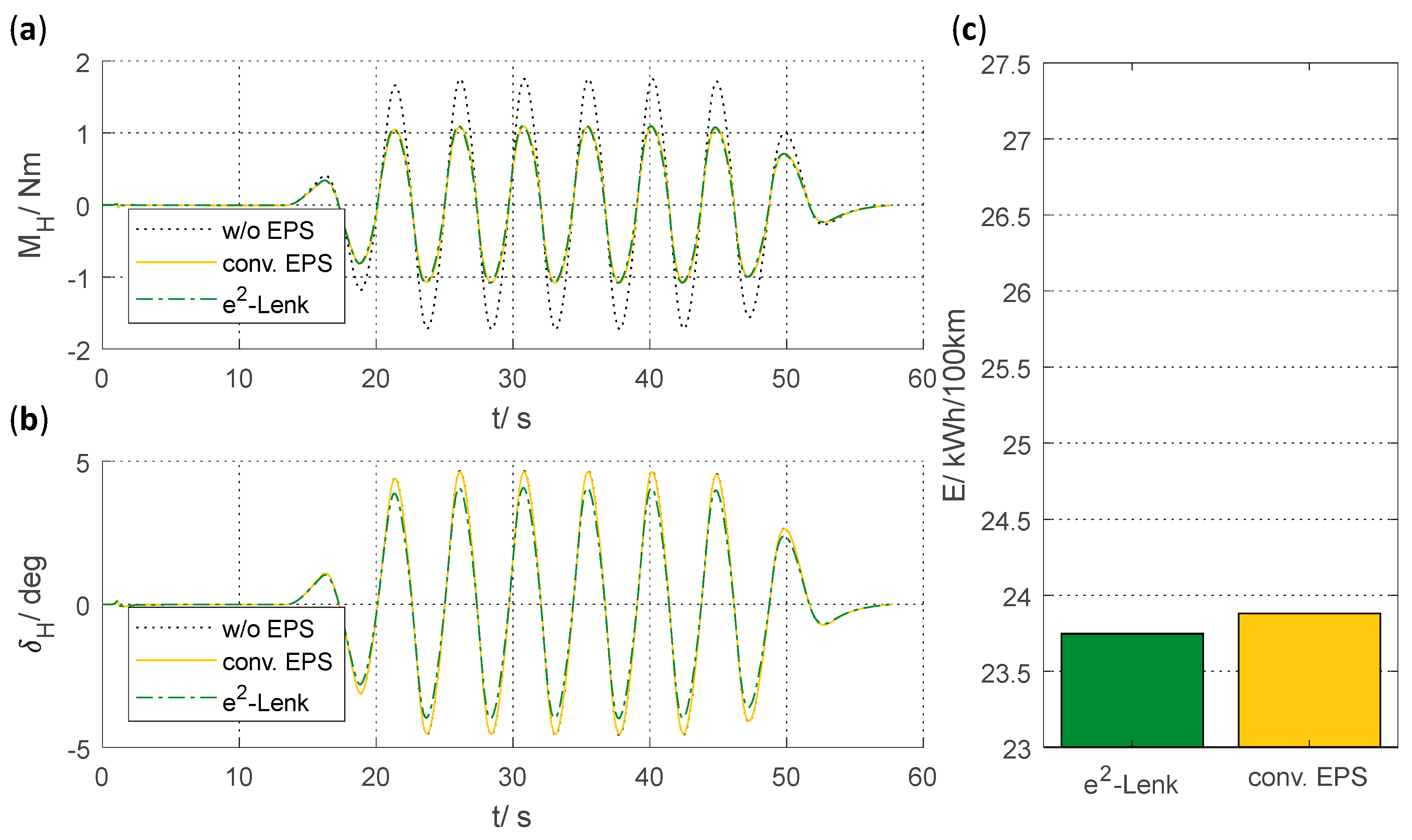
4.3.2. Double Lane Change
In double lane change, steering movement and high vehicle speed cause lateral accelerations of
. In this case, the absence of steering assistance causes a steering wheel torque of up to
(see
Figure 8a). Both assistance systems clearly reduce the driver’s steering effort by decreasing steering wheel torque by up to approximately 3.5 Nm. The assistance is almost identical in both systems except for a minor deviation in the case of rapid steering to one lane and switching back to the first lane. The root mean square deviation is
, with a maximum deviation of
. Moreover, the e
2-Lenk process reduces the required steering wheel angle by up to approximately 16% (see
Figure 8b). Despite the high dynamic demands on the driving motors, the e
2-Lenk process reduces the energy requirement compared to the conventional system by
(see
Figure 8c).
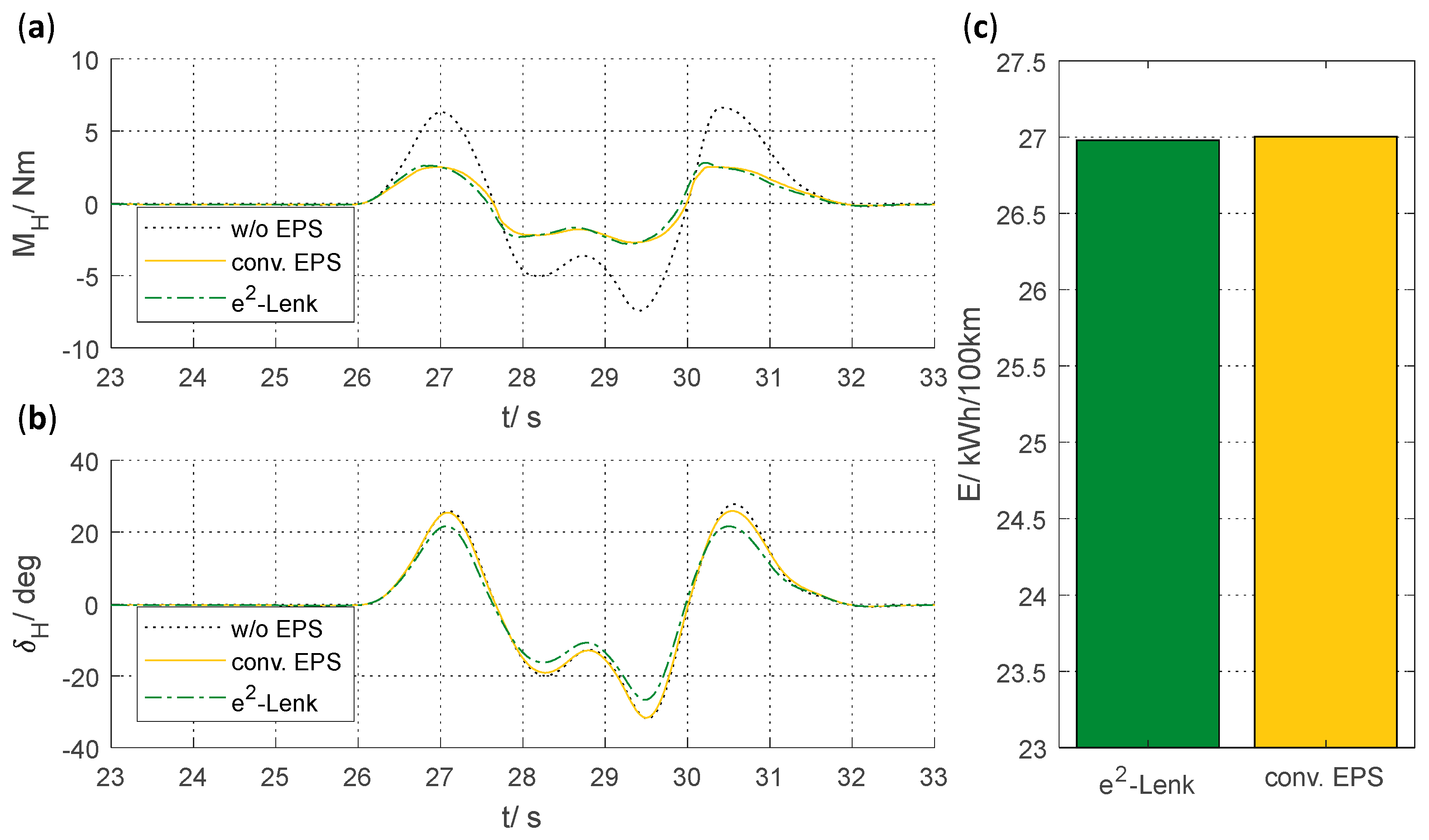
4.3.3. Slalom-Weave Manoeuvre
The slalom-weave manoeuvre simulates a situation with constant need of steering over a long period of time with moderate lateral accelerations. Without steering assistance, a steering wheel torque of up to
(see
Figure 9a) occurs, which can be reduced by both assistance systems by approximately 0.6 Nm. The steering wheel angle without steering assistance and with use of conventional EPS is identical (see
Figure 9b), while the e
2-Lenk system reduces the maximum steering wheel angle by approximately 12%. Furthermore, e
2-Lenk reduces the energy requirements by
(see
Figure 9c) compared to the conventional system. The result of driving manoeuvre show, that the vehicle is stable over long steering actions with e
2-Lenk.
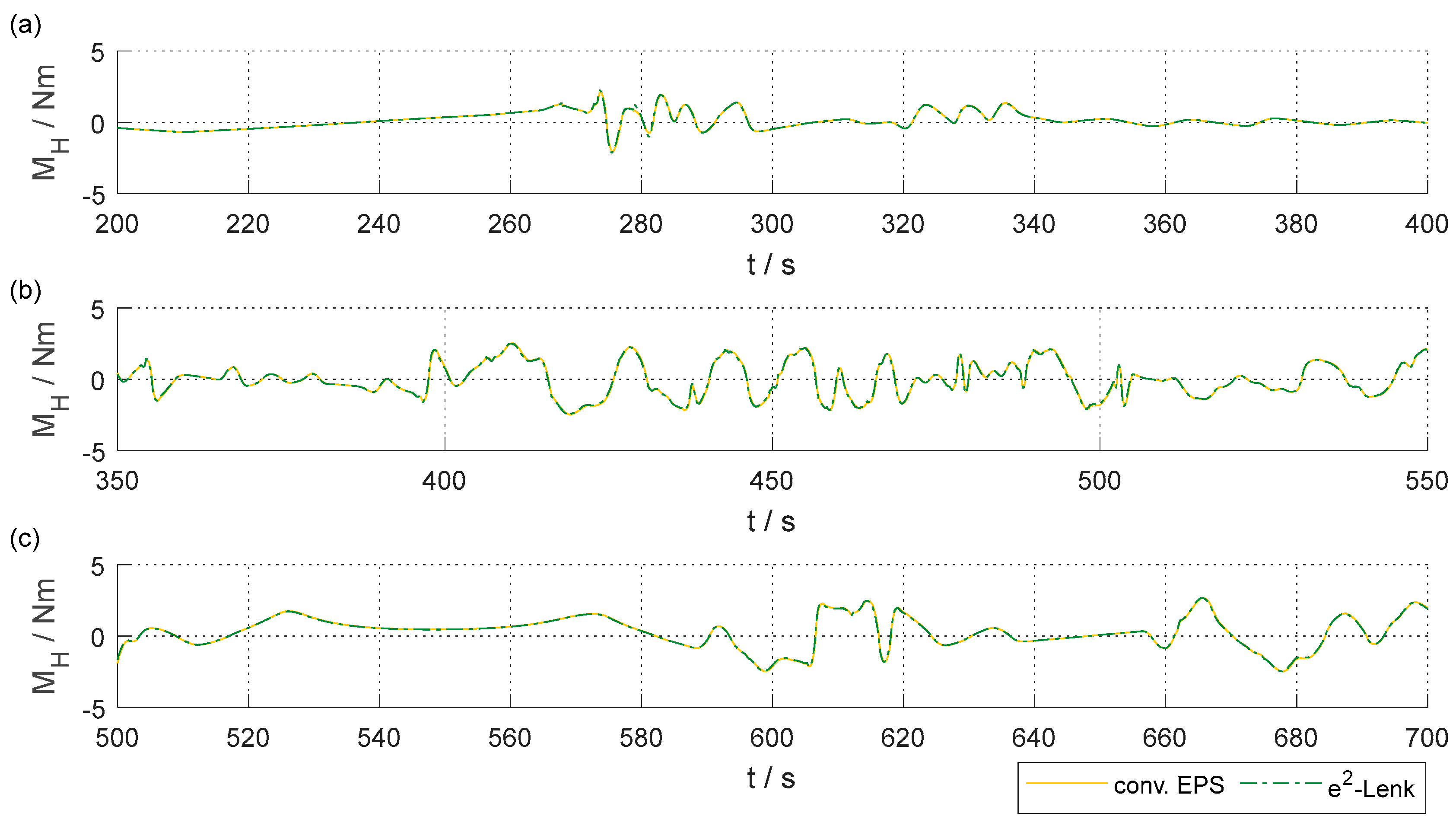
4.3.4. Realistic Driving Cycles
Also in realistic driving cycles, the assistance functions of conventional steering assistance and the e
2-Lenk approach show a high degree of agreement.
Figure 10 shows excerpts of the steering wheel torque occurring in the realistic driving cycles. The excerpts are representative of the entire course. Even with the occurring quasi-stochastic steering manoeuvers the same support as in the conventional system can be achieved. Thus, the driver’s steering torque is largely identical in both assistance variants (see
Table 1).
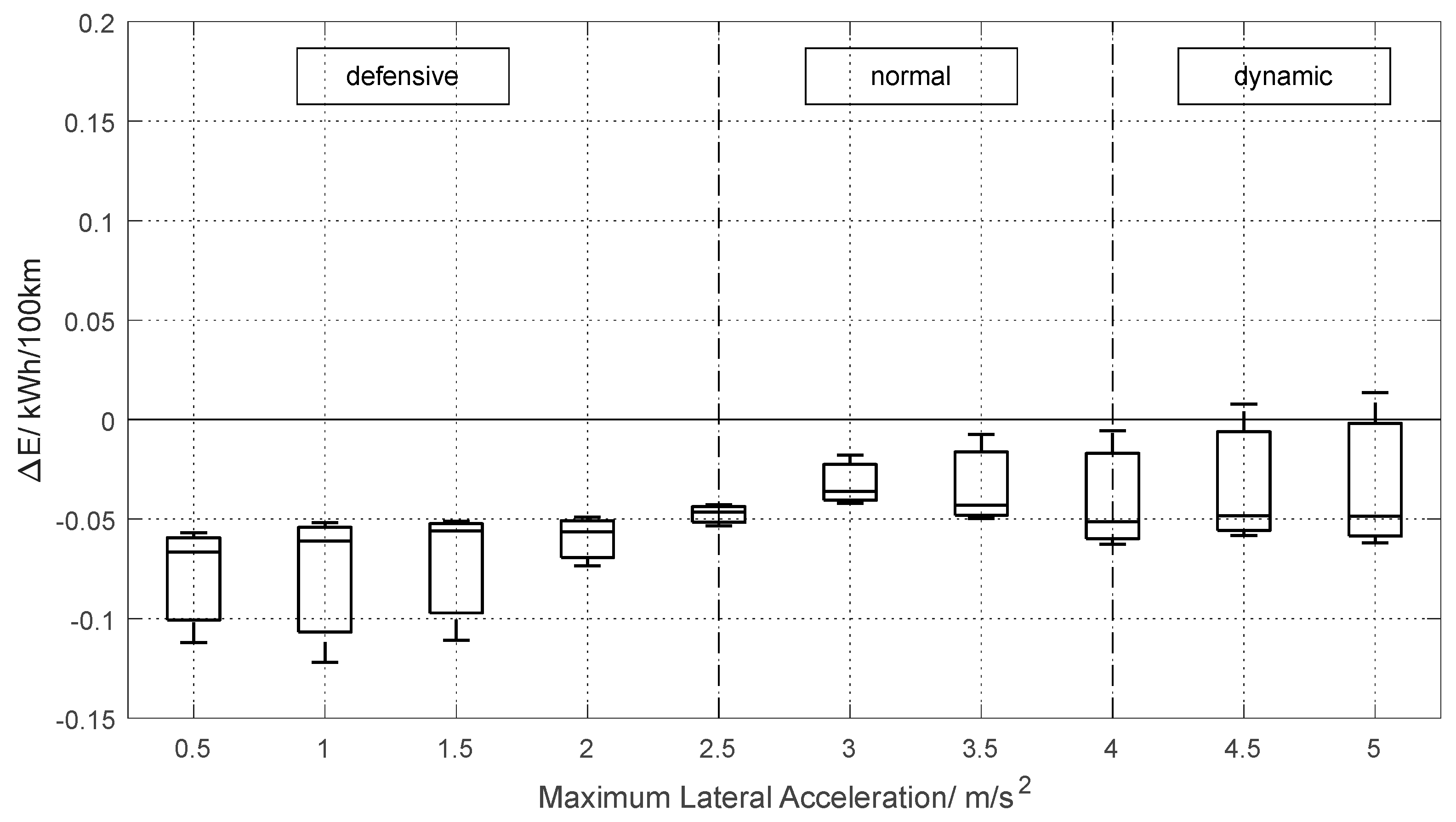
A comparison of the energy demand of the e
2-Lenk process and of a conventional steering assistance system is shown in
Figure 11. A box-whisker plot was drafted for the three realistic driving cycles within a defined maximum lateral acceleration of the virtual driver. This shows the potential of the e
2-Lenk process especially in a defensive mode of driving (the classification of types of drivers follows [
16,
17]). In this way, energy demand in lateral acceleration ranges below
can be reduced compared to conventional steering assistance systems by up to
respectively approximately 0.95%. Even in a dynamic mode of driving, energy demand can be reduced as a function of driving manoeuvre. This results in a median energy demand reduction in a range of approximately 0.28–0.64% with a mean median value of approximately 0.43%.
5. Summary
Various standard manoeuvres and realistic driving cycles show that operation of the e2-Lenk process for steering assistance and of conventional steering assistance systems achieve equivalent quality of driver assistance. This results in an equivalent influence on driver’s sensation with respect to the driver’s steering torque. In addition, e2-Lenk decreases the steering wheel angle by reducing the tire slip angle of the front axle. This reduces both the driver’s steering effort and tire rolling resistance.
Energetic analysis shows that steering assistance based on wheel-individual drives reduces energy demand compared to conventional power steering systems. Especially in defensive driving, the effect of reduced energy demand becomes most evident. An energy demand reduction of up to approximately 0.95% can be achieved in realistic driving cycles. The mean value is approximately 0.43%.
6. Conclusions
Our simulation-based investigations show the feasibility of a power steering system using wheel-individual drive torque at the front axle. We can establish that no dedicated actuators are needed for steering assistance, if wheel-individual drives and suspensions are properly used. This results in a slight reduction of energy demand and in gaining packaging space. To validate our data a real 1:1.5 scale model is in production.
The presented torque distribution algorithm is based on a classical EPS control plan in order to provide a meaningful energetic comparison. The use of more complex control methods will certainly provide further benefits for the e2-Lenk process and is the subject of further research. An optimized chassis design can further improve the assistance potential of the e2-Lenk process and reduce the energy demand even further. Undoubtedly, there is the potential for complete substitution of conventional power steering systems.


