Research on Energy-Saving Operation Strategy for Multiple Trains on the Urban Subway Line


Abstract
:1. Introduction
2. Introduction of the Multi-Train System and the Previous Study for the Single Train and Two-Train System
2.1. Parameters of the Subway Train 100% Low Floor Train
2.2. Parameters of the Traction Substation—Beijing Subway Line 4
2.3. Energy-Saving Operation Strategy for the Single Train
2.4. Energy-Saving Operation Strategy for the Two-Train System
3. The Energy-Saving Operation Strategy for Multi-Train System
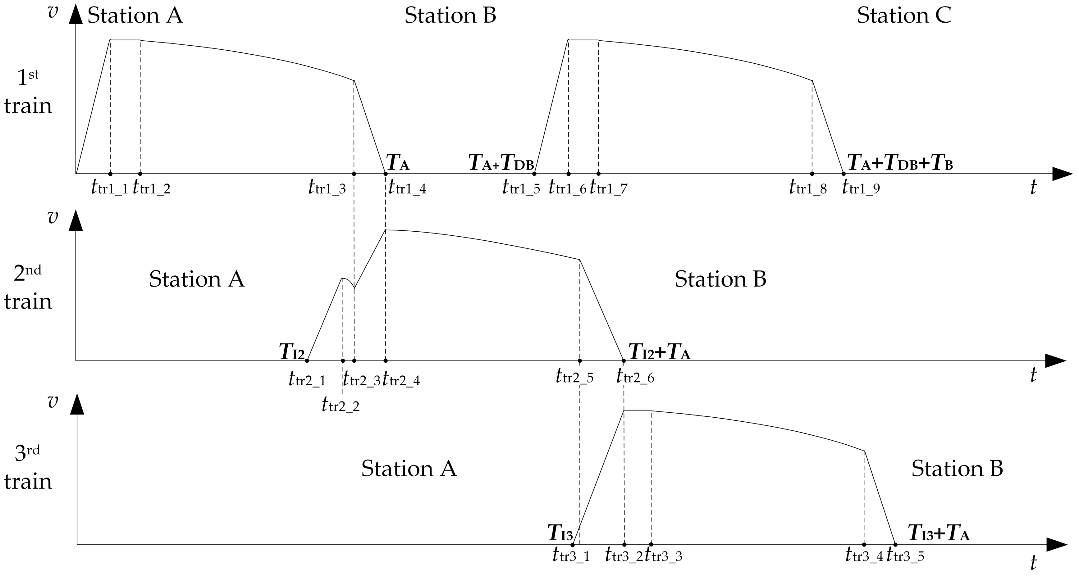
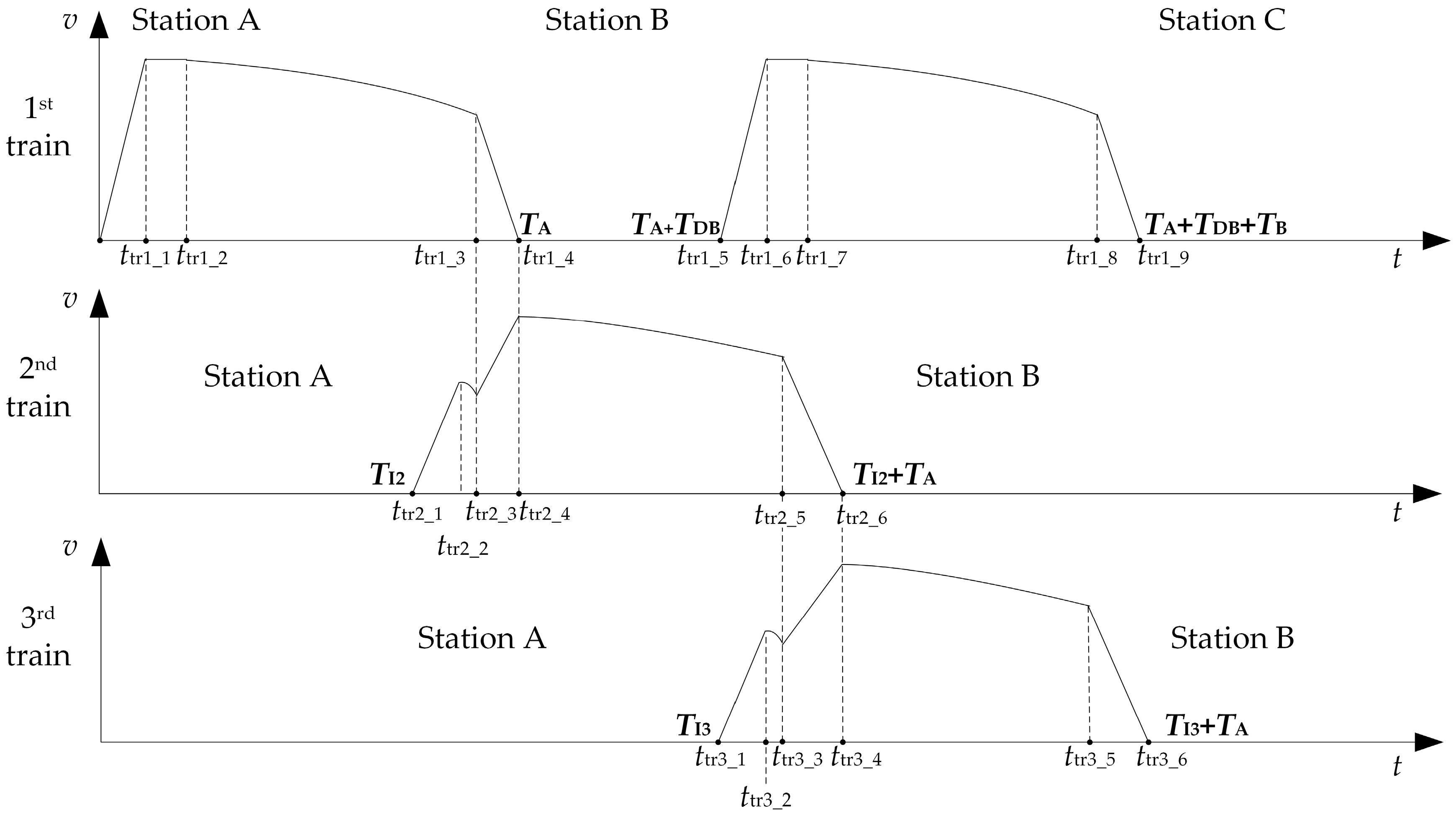
3.1. The Model of Multi-Train Cooperative Operation
3.2. Energy-Saving Driving Strategy of Multiple Trains
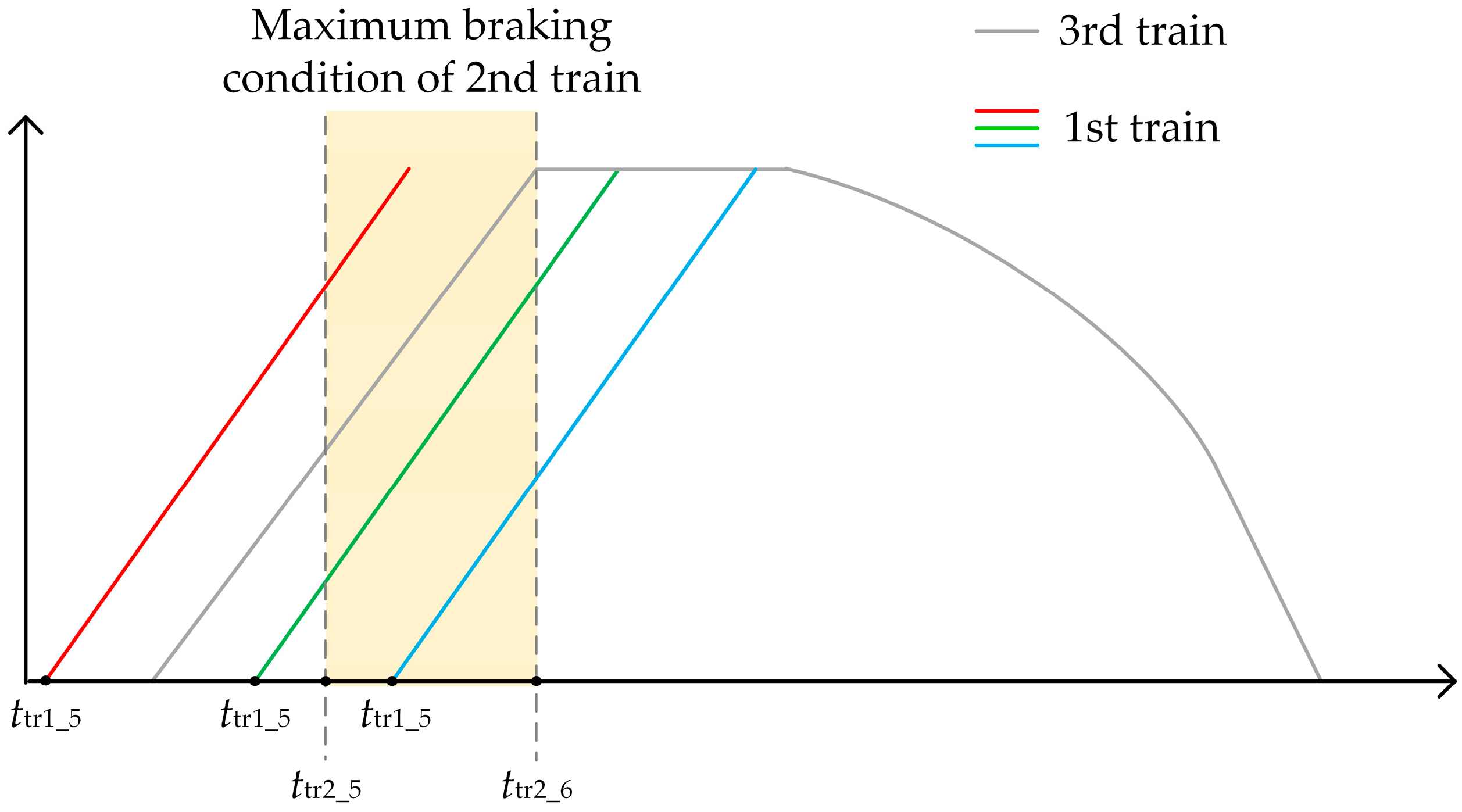
- When ttr1_5 ≤ ttr2_5 ≤ ttr1_6, the 1st train can use regenerative braking energy provided by the 2nd train. Meanwhile, the overlapping period is from ttr1_start = ttr2_5 to ttr1_end = ttr1_6.
- When ttr1_5 ≤ ttr2_5 ≤ ttr2_6 ≤ ttr1_6, the 1st train can use regenerative braking energy provided by the 2nd train. Meanwhile, the overlapping period is from ttr1_start = ttr2_5 to ttr1_end = ttr2_6.
- When ttr2_5 ≤ ttr1_5 ≤ ttr2_6, the 1st train can use regenerative braking energy provided by the 2nd train. Meanwhile, the overlapping period is from ttr1_start = ttr1_5 to ttr1_end = ttr2_6.
- Otherwise, there is no available regenerative braking energy when the 1st train departs from Station B again.
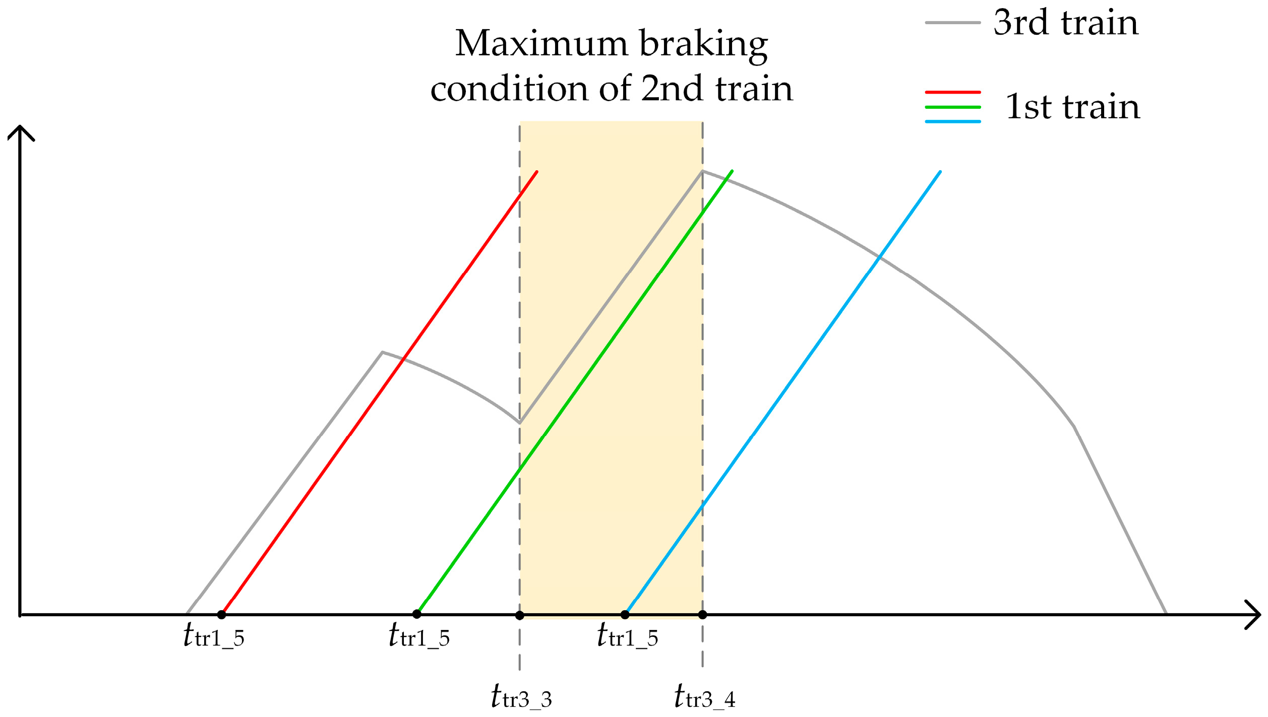
- When ttr1_5 ≤ ttr3_3 ≤ ttr1_6, the 1st train can use regenerative braking energy provided by the 2nd train. Meanwhile, the overlapping period is from ttr1_start = ttr3_3 to ttr1_end = ttr1_6.
- When ttr1_5 ≤ ttr3_3 ≤ ttr3_4 ≤ ttr1_6, the 1st train can use regenerative braking energy provided by the 2nd train. Meanwhile, the overlapping period is from ttr1_start = ttr3_3 to ttr1_end = ttr3_4.
- When ttr3_3 ≤ ttr1_5 ≤ ttr3_4, the 1st train can use regenerative braking energy provided by the 2nd train. Meanwhile, the overlapping period is from ttr1_start = ttr1_5 to ttr1_end = ttr3_4.
- Otherwise, there is no available regenerative braking energy when the 1st train departs from Station B again.
- The 3rd train operates under four-mode operation or five-mode operation and is ensured to use the regenerate energy firstly.
- The 1st train under different dwell time tries to use the regenerate energy of the 2nd train as much as possible.
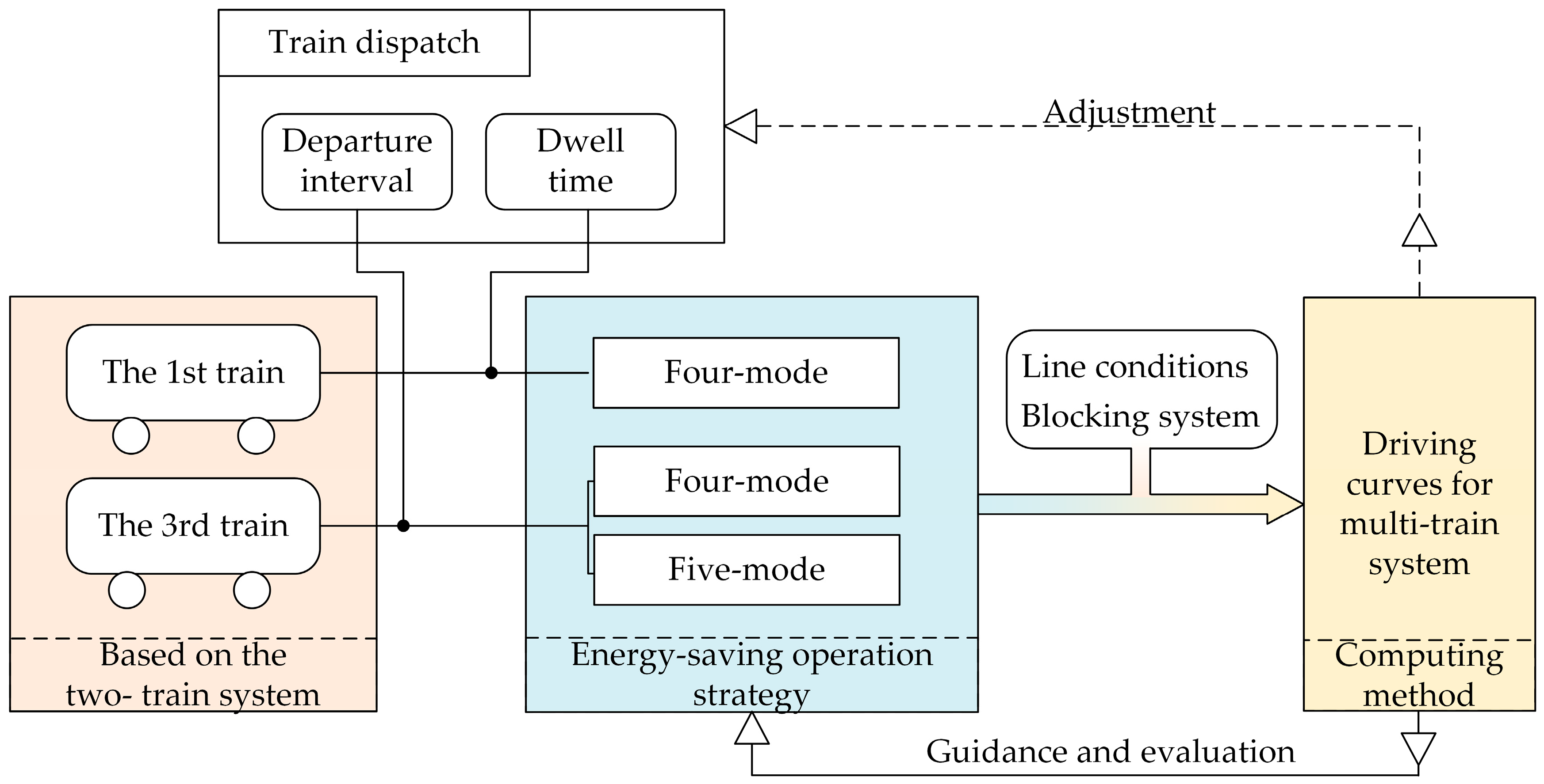
- The energy-saving operation strategy only provides the available operation modes (four-mode operation and five-mode operation) for the multi-train system, which can be regarded as the guidance for the computing method. The computing method solves the switching points and the drive curves under different modes and finally chooses the optimum drive curves and the optimum operation mode for the multi-train system.
3.3. Computing Method for Energy-Saving Driving Strategy of Multiple Trains
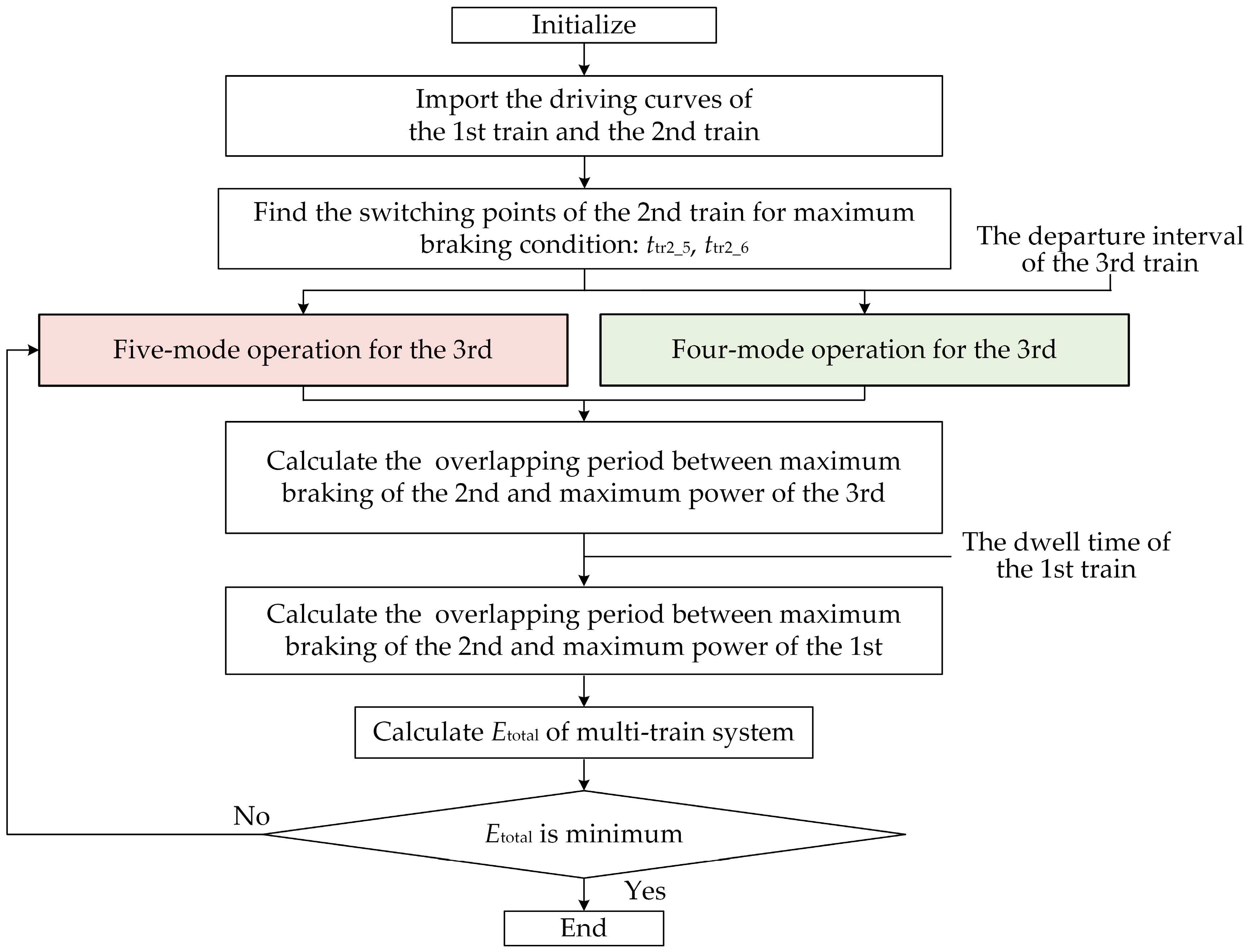
- Initialize. Determine the parameters of urban subway train and traction substation.
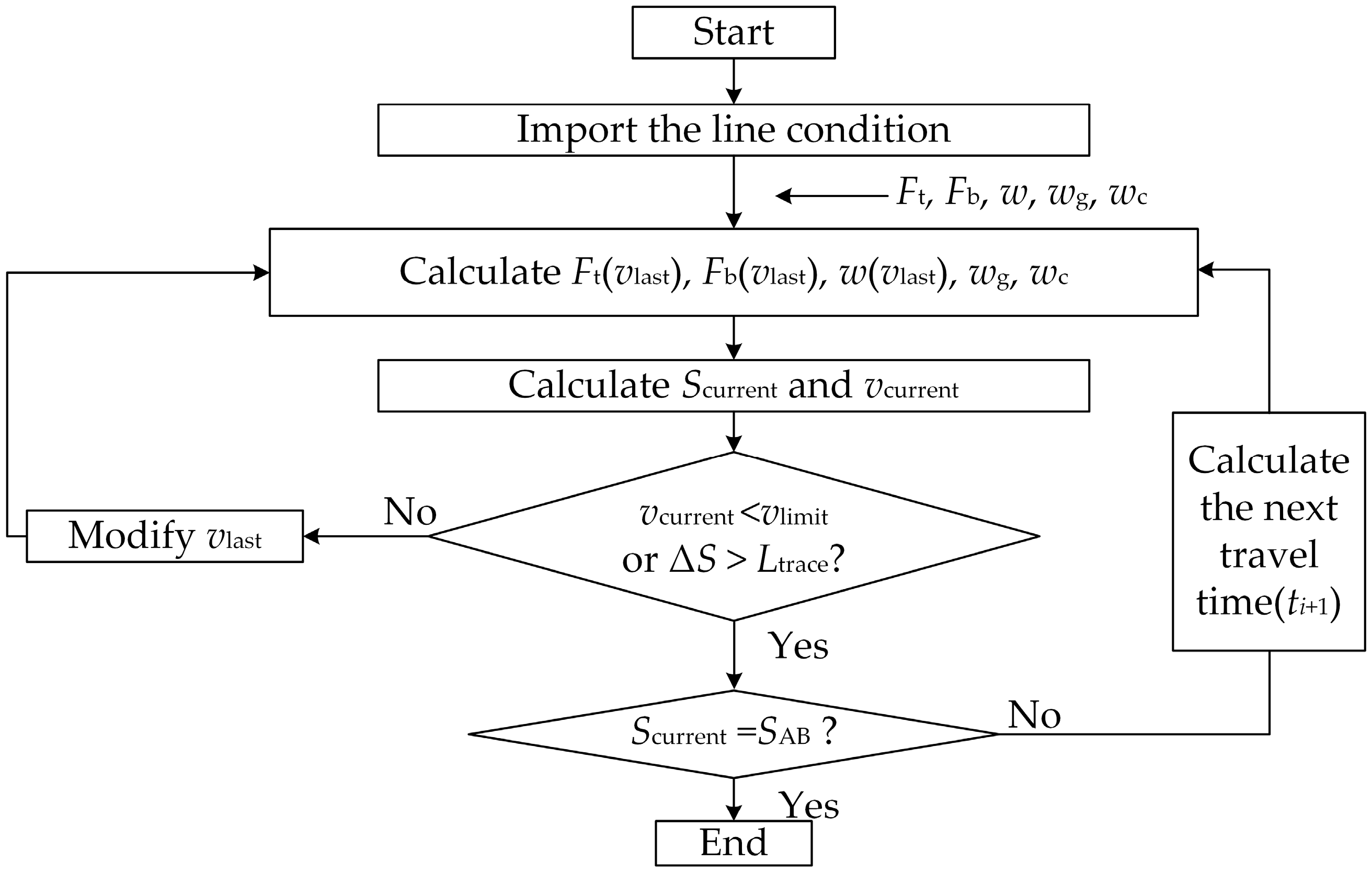
- Import the line conditions (including the limiting velocity, the unit curve and slope resistance).
- Import the driving curves of the 1st train and the 2nd train which can be obtained based on the energy-saving operation strategy for the two-train system.
- Find the switching points ttr2_5 and ttr2_6 (directly obtain from the driving curves).
- Calculate Etotal. The calculating progress can be realize by Equations (4)–(9). Choose minimum energy consumption (Emin) and determine the optimum driving mode and driving curves for the 1st train and the 3rd train.
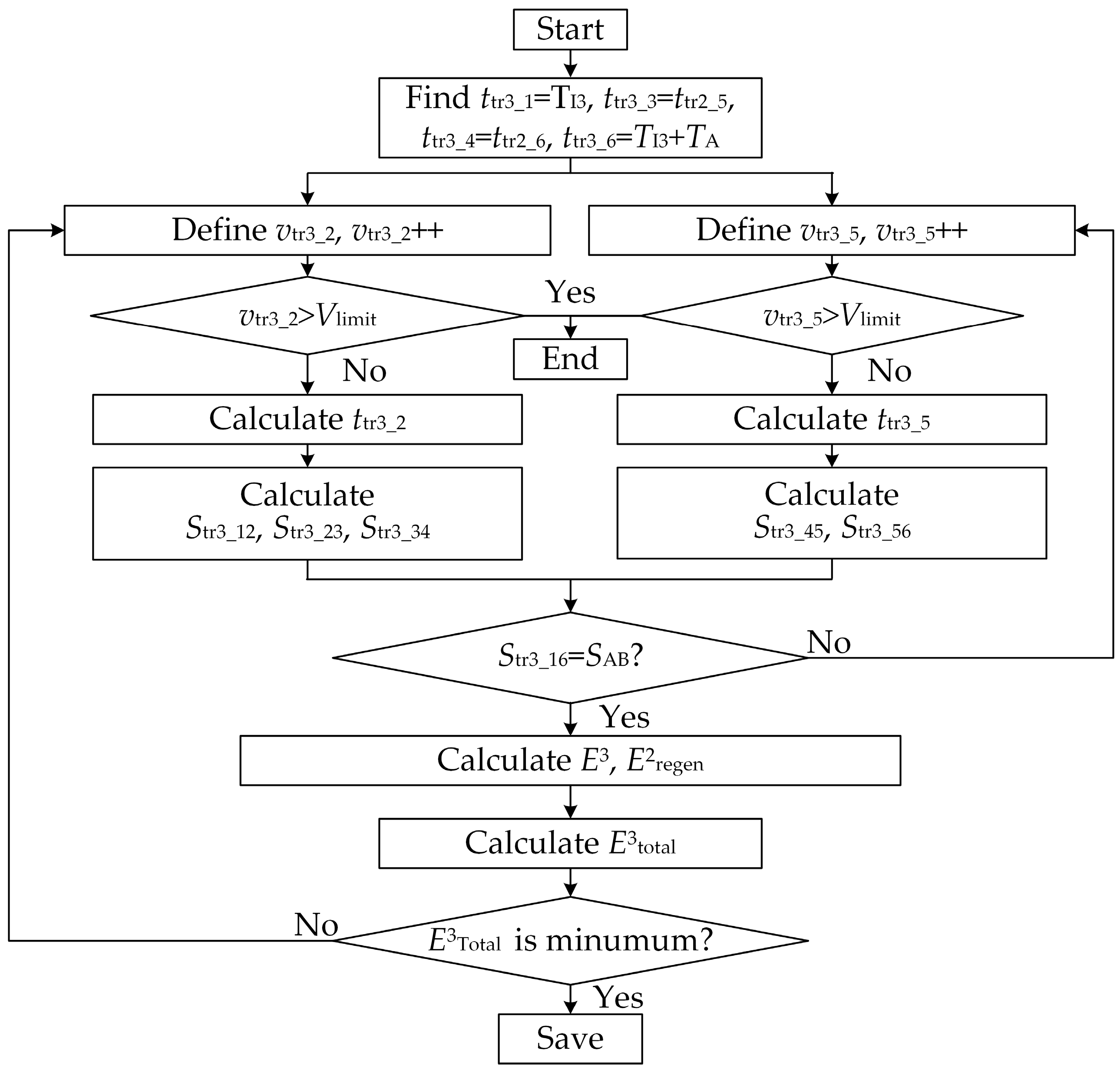
- Determine the known switching points of the 3rd train. ttr3_1 equals to the departure interval of the 3rd train (TI3), ttr3_3 is the switching point when the 2nd train starts braking (ttr2_5), ttr3_4 is the switching point when the 2nd train stops braking (ttr3_6), and ttr3_6 equals to the departure interval plus the travel time from Station A to Station B (TI3 + TAB). The unknown switching points are ttr3_2 and ttr3_5.
- Two loops are built to gain the unknown switching points. Firstly, define the vtr3_2. Then, ttr3_2 can be calculated based on the line conditions. Since the ttr3_1, ttr3_2, ttr3_3 and ttr3_4 are known, the Str3_12, Str3_23 and Str3_34 can be calculated.
- Under the circumstance that the vtr3_2 is determined, define vtr3_5. The ttr3_5 can be calculated. Since the ttr3_4, ttr3_5 and ttr3_6 are known, the Str3_45 and Str3_56 can be calculated.
- If the total travel distance Str3_16(Str3_12 + Str3_23 + Str3_34 + Str3_45 + Str3_56) does not equals to the distance SAB between Station A and Station B, the vtr3_5 will be added with a small increment and back to the Step 3 of the process. Moreover, if Str3_16 equals the S, the current (ttr3_2, vtr3_2) and (ttr3_5, vtr3_5) will be saved as one solution for the five-mode operation.
- Calculate total energy consumption of the 3rd train E3total.
- A small increment is added to vtr3_2, and back to step 2, 3, 4 again.
- Choose minimum energy consumption of the 3rd train, and the corresponding driving curve is defined as the optimum driving curve for the 3rd train under five-mode operation.
3.4. Conclusion of the Energy-Saving Operation Strategy
4. Simulation Results and Analysis
4.1. Results of Simulation
4.2. Analysis
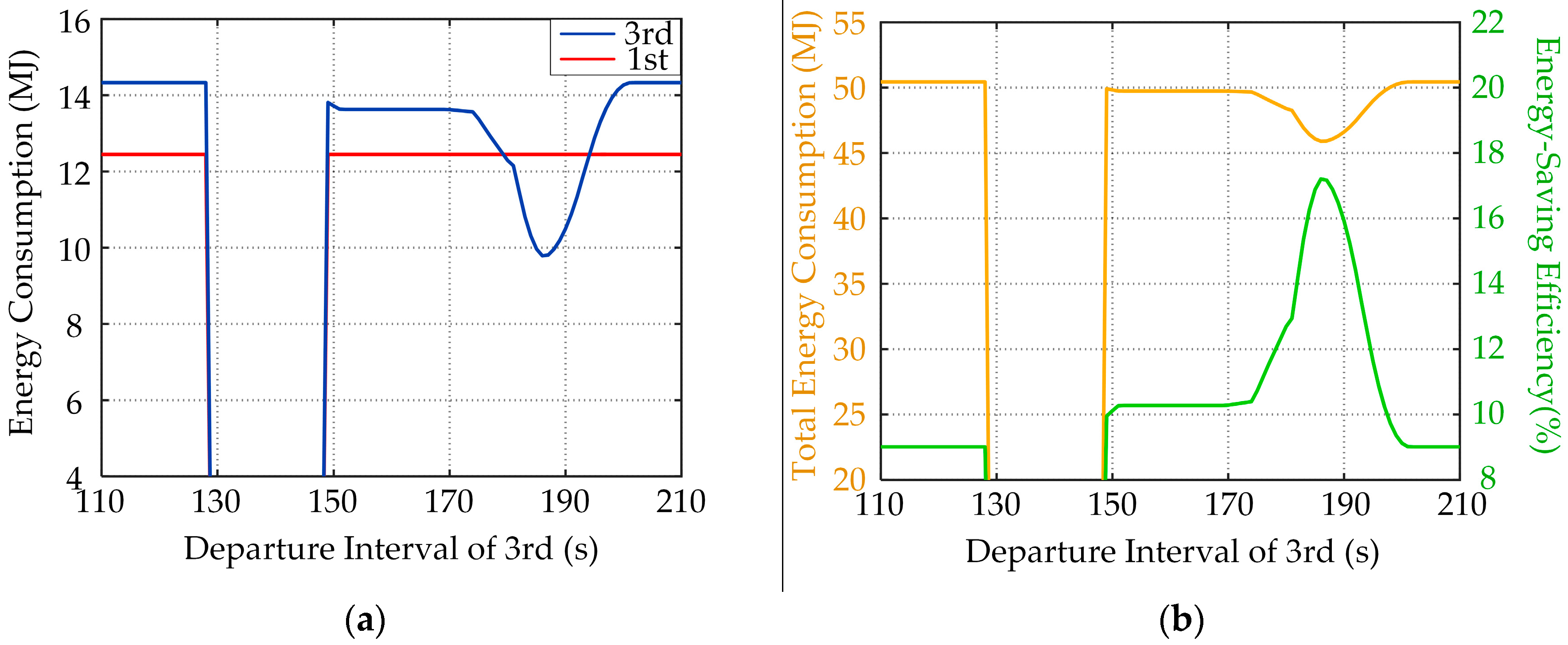
- When the departure interval and the dwell time are certain, the optimum operation mode and driving curves for the multi-train system can be obtained by the proposed energy-saving operation strategy. For example, when the dwell time of the 1st train is 30 s, and the departure interval is between 110 s and 186 s, the five-mode operation is suitable for the 3rd train, and, when the departure interval is after 186 s, four-mode operation is suitable for the 3rd train. The driving curves can be obtained by the corresponding computing method.
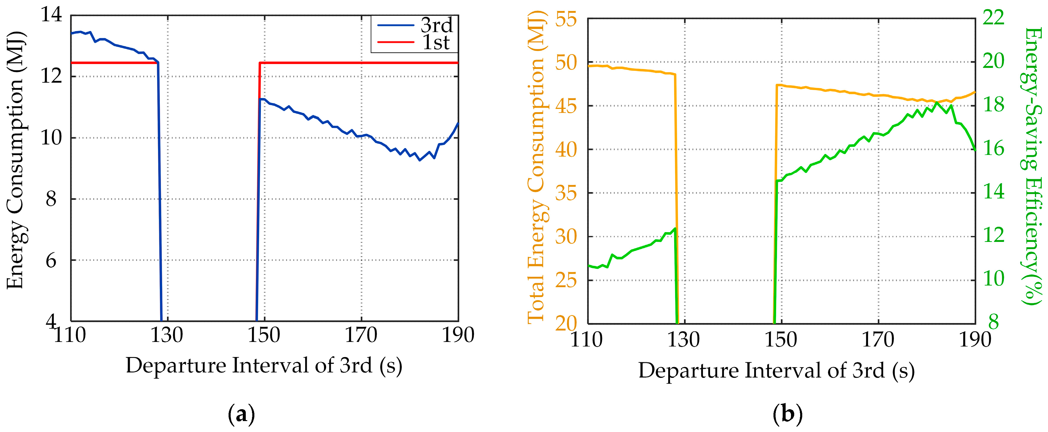
- When the dwell time is specified and the departure interval is adjustable, the optimum departure interval can be obtained to realize minimum energy consumption for the multi-train system by the proposed energy-saving operation strategy. For example, when the dwell time of the 1st train is 30 s, the optimum departure interval for the 3rd train is 182 s and the current energy-saving efficiency is 18.15%.
- When the dwell time is adjustable, the optimum dwell time for the 1st train can be obtained to make full use of the 2nd train’s regenerate energy. For example, when the dwell time is 50 s, the total energy consumption is the minimum, and the energy-saving efficiency is 18.24%.
- The computing method can work under complex circumstance considering the line conditions and the moving automatic block system. For example, the 3rd train is not allowed to depart when the 1st train starts accelerating.
- The proposed energy-saving operation strategy is suitable for both online and offline operation. When the departure interval and the dwell time are given by train dispatch, the operation strategy with velocity adjustment and moving automatic block system can gain the driving curves quickly. Moreover, the strategy is also suitable for offline calculation because energy consumption results under different departure intervals and dwell times can be calculated to guide and adjust the train dispatch.
- The proposed energy-saving operation strategy not only can be applied to the three-train system but can also be generalized to other multi-train systems. As in the previous example, one traction substation contains at most three trains, so the three trains can be regarded as a group. All the trains on one subway line depart by groups. For the three-train group, after the 1st train departs again from Station B, the whole system can be regarded to operate for a new circulation, so the energy-saving operation strategy is fit for the 2nd train and the 3rd train departing from station B again. For other multi-train systems that one traction substation contains more than three trains, the computing method is also able to calculate the driving curves for rest of the trains under different dwell times and departure intervals.
5. Conclusions
Acknowledgments
Author Contributions
Conflicts of Interest
Abbreviations
| Ft(v) | Traction force |
| w(v) | Running resistance |
| wc | Unit curve resistance |
| Ejtrac | Tractive energy consumption for the jth train |
| Tunit_i | Unit time |
| vi | Speed |
| si | Travel distance |
| nb | Braking force coefficient |
| eb_j_i | Braking energy of jth train in unit time |
| TX | Travel time from Station X to next station |
| TIm | Departure interval for the train m |
| Strm_ij | Distance traveled by the mth train in the period (ttrm_i, ttrm_j) |
| Vmax | Maximum speed |
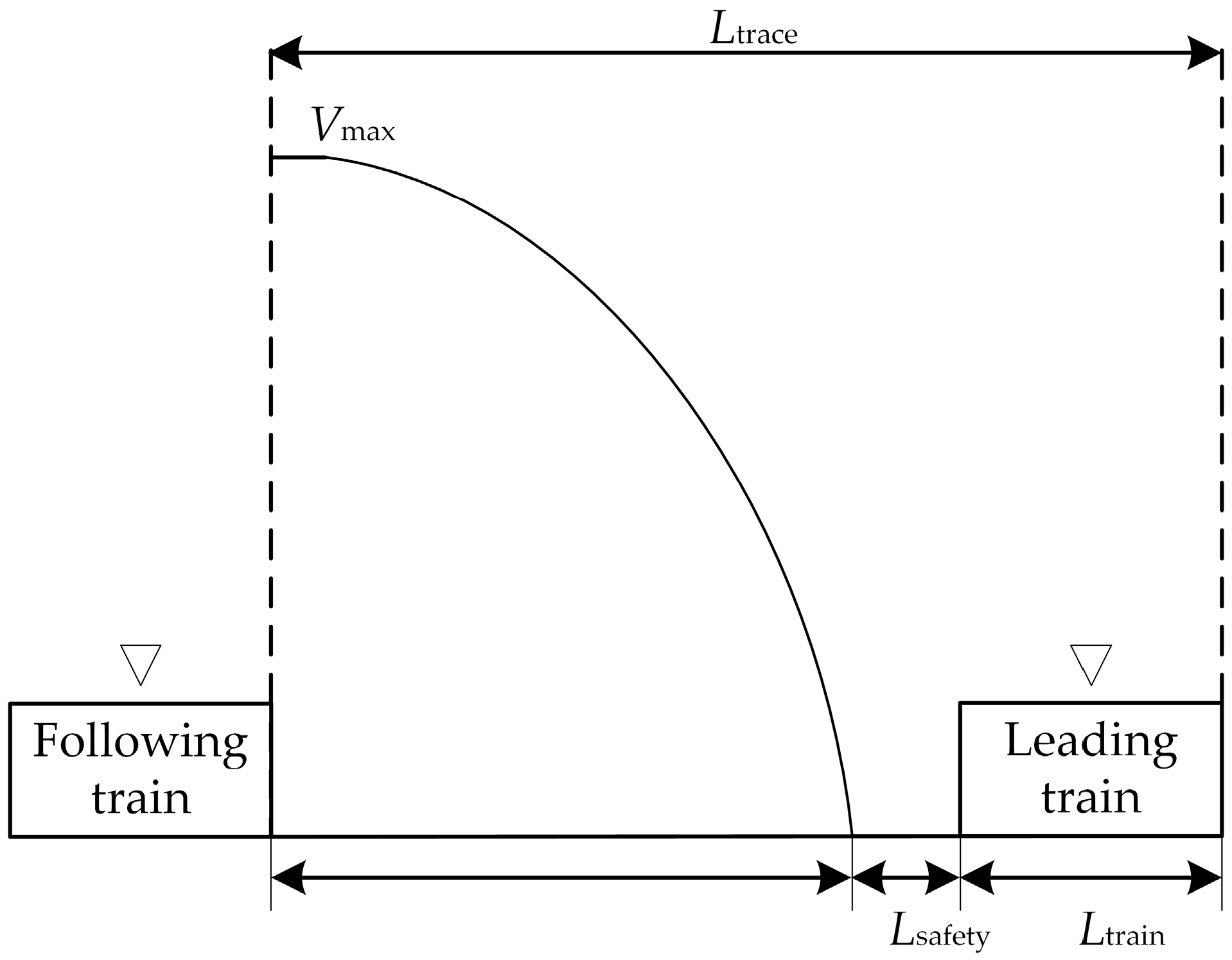
| Ltrain | Length of the train |
| vlast | Velocity of last unit time |
| Slast | Travel distance of last unit time |
| ΔS | Distance between two trains |
| Fb(v) | Braking force |
| wg | Unit gradient resistance |
| Etotal | Total energy consumption |
| Ejregen | Available regenerative braking energy for the jth train |
| n | Total number of unit times |
| ti | Travel time |
| nt | Traction coefficient |
| etrac_j_i | Traction energy consumption of jth train in unit time |
| ttrm_k | kth switching point for train m |
| TDX | Dwell time of Station X |
| vtrm_k | Velocity at ttrm_k for train m |
| Ltrace | Tracing distance |
| Lsafety | Safe distance |
| b | Deceleration coefficient |
| vcurrent | Velocity of current unit time |
| Scurrent | Travel distance of current unit time |
| M | Mass of the train |
References
- Liu, J.; Wei, Y.; Hu, H. research on the optimization control method of energy-saving operation for high-speed train. China Railw. Soc. 2014, 36, 7–12. (In Chinese) [Google Scholar]
- Albrecht, A.R.; Howlett, P.G.; Pudney, P.J.; Vu, X. Energy-efficient train control: From local convexity to global optimization and uniqueness. Automatica 2013, 49, 3072–3078. [Google Scholar] [CrossRef]
- Howlett, P.G.; Pudney, P.J.; Vu, X. Local energy minimization in optimal train control. Automatica 2009, 45, 2692–2698. [Google Scholar] [CrossRef]
- Wang, Q.; Feng, X. Optimal switching for control conditions of punctual and energy efficient operation of train. China Railw. Soc. 2016, 37, 91–98. (In Chinese) [Google Scholar]
- Yang, X.; Li, X.; Ning, B.; Tang, T. A Survey on energy-efficient train operation for urban rail transit. IEEE Trans. Intell. Transp. Syst. 2016, 17, 2–13. [Google Scholar] [CrossRef]
- Albrecht, A.R.; Howlett, P.G.; Pudney, P.J.; Vu, X.; Zhou, P. Energy-efficient train control: The two-train separation problem on level track. J. Rail Trans. Plan. Manag. 2015, 5, 163–182. [Google Scholar] [CrossRef]
- Yang, X.; Li, X.; Gao, Z.; Wang, H.; Tang, T. A cooperative scheduling model for timetable optimization in subway systems. IEEE Trans. Intell. Transp. Syst. 2013, 14, 438–447. [Google Scholar] [CrossRef]
- Yang, X.; Li, X.; Ning, B.; Tang, T. An optimisation method for train scheduling with minimum energy consumption and travel time in metro rail systems. Transp. B Transp. Dyn. 2015, 3, 79–98. [Google Scholar] [CrossRef]
- Yang, X.; Chen, A.; Li, X.; Ning, B.; Tang, T. An energy-efficient scheduling approach to improve the utilization of regenerative energy for metro systems. Transp. Res. Part C 2015, 57, 13–29. [Google Scholar] [CrossRef]
- Yang, X.; Chen, A.; Ning, B.; Tang, T. A stochastic model for the integrated optimization on metro timetable and speed profile with uncertain train mass. Transp. Res. Part B Methodol. 2016, 91, 424–445. [Google Scholar] [CrossRef]
- Bin, N.; Jing, X.; Shigen, G.; Lingying, Z. An integrated control model for headway regulation and energy saving in urban rail transit. IEEE Trans. Intell. Transp. Syst. 2015, 16, 1469–1478. [Google Scholar]
- Li, X.; Lo, H.K. An energy-efficient scheduling and speed control approach for metro rail operations. Transp. Res. Part B 2014, 64, 73–89. [Google Scholar] [CrossRef]
- Li, X.; Lo, H.K. Energy minimization in dynamic train scheduling and control for metro rail operations. Transp. Res. Part B 2014, 70, 269–284. [Google Scholar] [CrossRef]
- Su, S.; Li, X.; Tang, T.; Gao, Z. A subway train timetable optimization approach based on energy-efficient operation strategy. IEEE Trans. Intell. Transp. Syst. 2013, 14, 883–893. [Google Scholar] [CrossRef]
- Su, S.; Tang, T.; Li, X.; Gao, Z. Optimization of multitrain operations in a subway system. IEEE Trans. Intell. Transp. Syst. 2014, 15, 673–685. [Google Scholar]
- Liu, J.; Guo, H.; Yu, Y. Research on the cooperative train control strategy to reduce energy consumption. IEEE Trans. Intell. Transp. Syst. 2017, 18, 1134–1142. [Google Scholar] [CrossRef]
- Liu, H.; Mao, B.; He, T.; Ding, Y.; Wang, X. Study on tracking operations between trains of difference block modes and simulation system. China Railw. Soc. 2005, 27, 121–125. (In Chinese) [Google Scholar]
- Gu, Q.; Tang, T.; Song, Y. A survey on energy-saving operation of railway transportation systems. Meas. Control 2010, 43, 209–211. [Google Scholar] [CrossRef]
- Gu, Q.; Tang, T.; Cao, F.; Song, Y. Energy-efficient train operation in urban rail transit using real-time traffic information. IEEE Trans. Intell. Transp. Syst. 2014, 15, 1216–1233. [Google Scholar] [CrossRef]
- Gu, Q.; Meng, Y.; Ma, F. Energy saving for automatic train control in moving block signaling system. China Commun. 2014, 11, 12–22. [Google Scholar] [CrossRef]
- Jiang, Y.; Liu, J.Q.; Tian, W.; Shahidehpour, M.; Krishanurthy, M. Harvesting for the electrification of railway stations: Getting a charge from the regenerative braking of trains. IEEE Electr. Mag. 2014, 2, 39–48. [Google Scholar] [CrossRef]
- Zhen, T.; Zhang, M. Design and calculation of traction power supply system. In Traction Power Supply System for Urban Rail Transit, 1st ed.; Su, G.R., Ed.; China Railway Publishing House: Beijing, China, 2003; Volume 6, pp. 134–143. ISBN 978-7-11-303674-4. [Google Scholar]


| Slope Conditions | Curve Conditions | |||||
|---|---|---|---|---|---|---|
| Station | Section (km) | Gradient (‰) | Travel Time (s) | Section (km) | Curve Radius (m) | Limiting Velocity (km/h) |
| Anheqiao North | 0.000–0.030 | −8.00 | 109 | 0.100–0.268 | 400 | 63.7792 |
| 0.030–0.200 | 23.00 | 0.860–0.974 | 2000 | 77.0208 | ||
| 0.20–0.860 | 2.00 | 0.994–1.143 | 1000 | 74.2191 | ||
| 0.860–1.060 | 3.00 | 1.164–1.298 | 2000 | 77.0208 | ||
| 1.060–1.363 | −4.00 | |||||
| Beigongmen | 1.363–1.420 | −4.00 | 93 | 1.613–1.670 | 3000 | 61.7540 |
| 1.420–1.640 | 2.00 | 1.772–1.958 | 2000 | 77.0208 | ||
| 1.640–1.880 | 3.25 | 1.983–2.131 | 2000 | 77.0208 | ||
| 1.880–2.245 | −3.00 | 2.469–2.614 | 600 | 67.6481 | ||
| 2.245–2.465 | 2.00 | |||||
| 2.465–2.614 | −15.00 | |||||
| Xiyuan | 2.614–2.950 | −15.00 | - | 2.614–2.993 | 600 | 67.6481 |
| Station | Tractive Energy Consumption (MJ) | Regenerative Braking Energy (MJ) | Total Energy Consumption (MJ) |
|---|---|---|---|
| A–B | 14.330454 | 4.861847 | 9.468607 |
| B–C | 12.446502 | 5.634088 | 6.812414 |
| Energy Consumption | Two-Train Strategy | Single Train Strategy |
|---|---|---|
| energy consumption of the 2nd (MJ) | 9.040636 | 9.587708 |
| total energy consumption of two trains (MJ) | 23.371090 | 23.918162 |
| Five-Mode Operation | Four-Mode Operation | ||||
|---|---|---|---|---|---|
| Dwell Time (s) | Total Energy Consumption (MJ) | Efficiency (%) | Dwell Time (s) | Total Energy Consumption (MJ) | Efficiency (%) |
| 30 | 45.37766 | 18.15 | 30 | 45.89939 | 17.21 |
| 40 | 45.37766 | 18.15 | 40 | 45.89939 | 17.21 |
| 50 | 45.32823 | 18.24 | 50 | 45.80053 | 17.31 |
© 2017 by the authors. Licensee MDPI, Basel, Switzerland. This article is an open access article distributed under the terms and conditions of the Creative Commons Attribution (CC BY) license (http://creativecommons.org/licenses/by/4.0/).
Share and Cite
Liu, J.; Zhao, N. Research on Energy-Saving Operation Strategy for Multiple Trains on the Urban Subway Line. Energies 2017, 10, 2156. https://doi.org/10.3390/en10122156
Liu J, Zhao N. Research on Energy-Saving Operation Strategy for Multiple Trains on the Urban Subway Line. Energies. 2017; 10(12):2156. https://doi.org/10.3390/en10122156
Chicago/Turabian StyleLiu, Jianqiang, and Nan Zhao. 2017. "Research on Energy-Saving Operation Strategy for Multiple Trains on the Urban Subway Line" Energies 10, no. 12: 2156. https://doi.org/10.3390/en10122156