Integration Design and Optimization Control of a Dynamic Vibration Absorber for Electric Wheels with In-Wheel Motor


Abstract
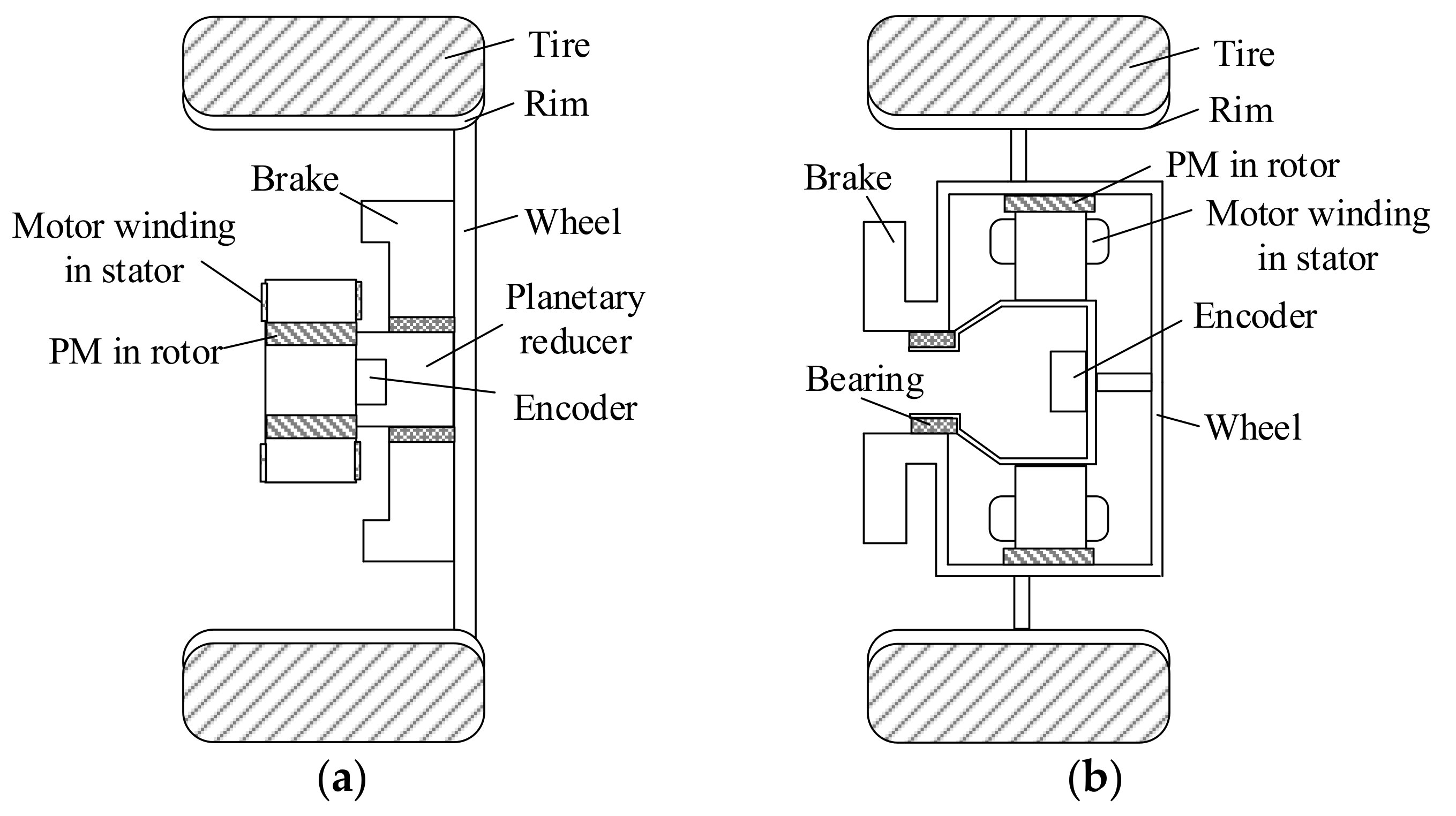
:1. Introduction
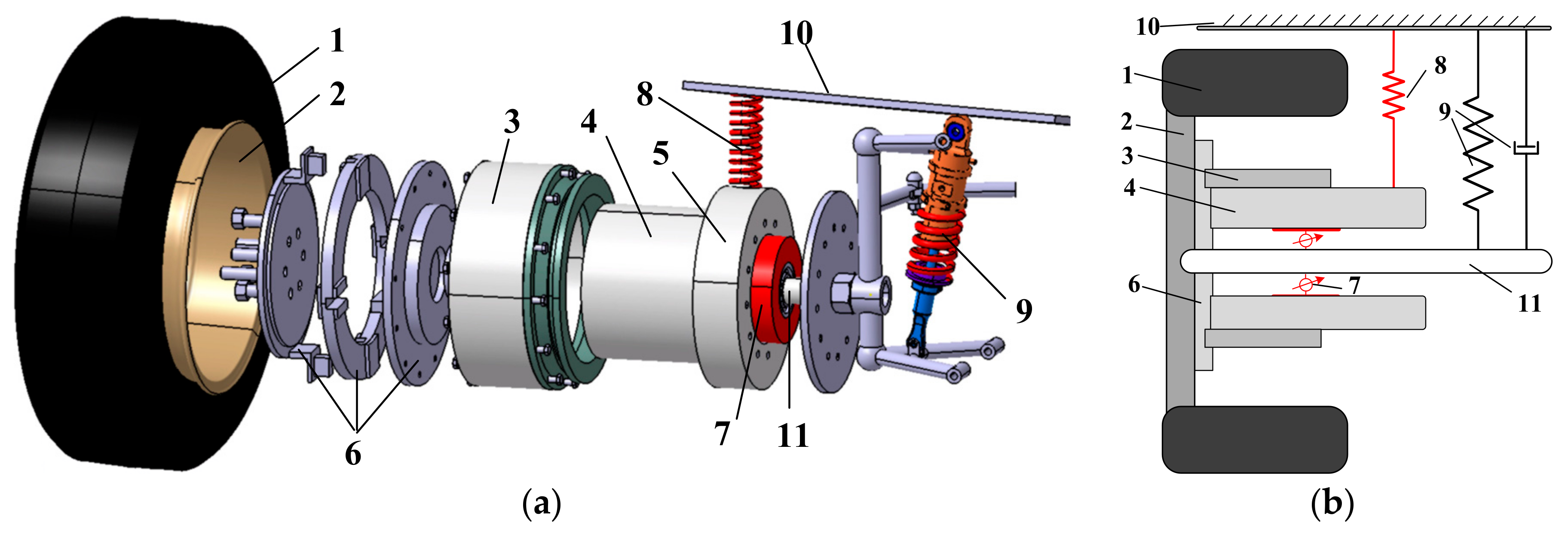
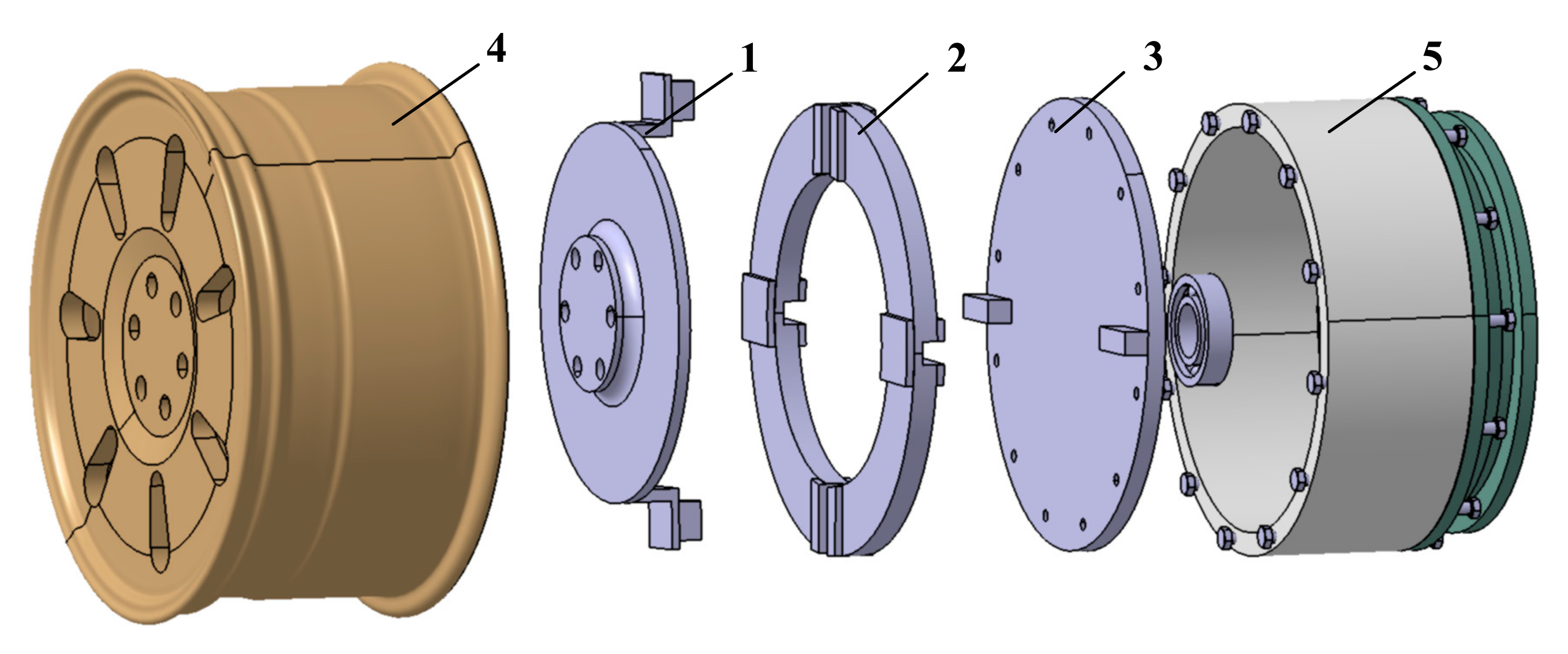
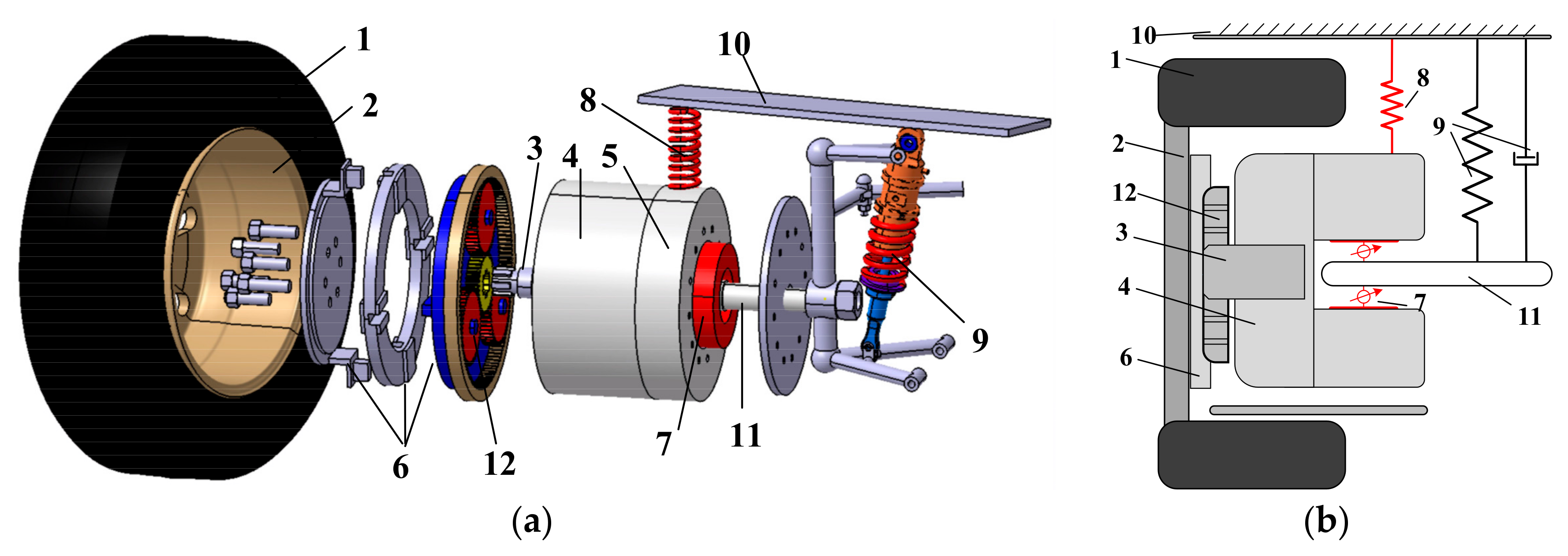
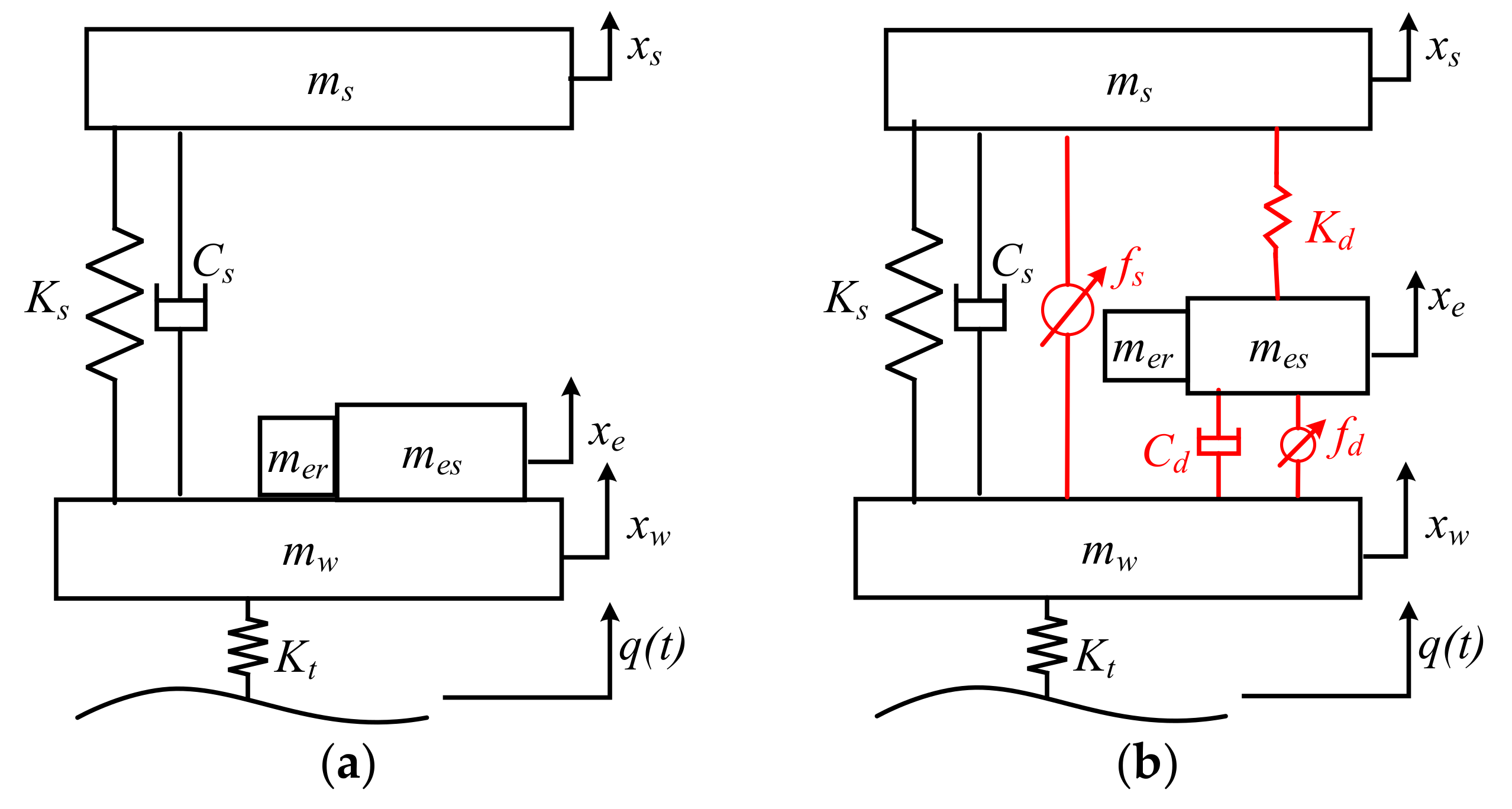
2. Integration Designed of the Dynamic-Vibration-Absorber-Based Electric Wheel
3. Quarter-Vehicle System Modeling and Problem Statement
3.1. Quarter-Vehicle System Modeling
3.2. Problem Statement
- (1)
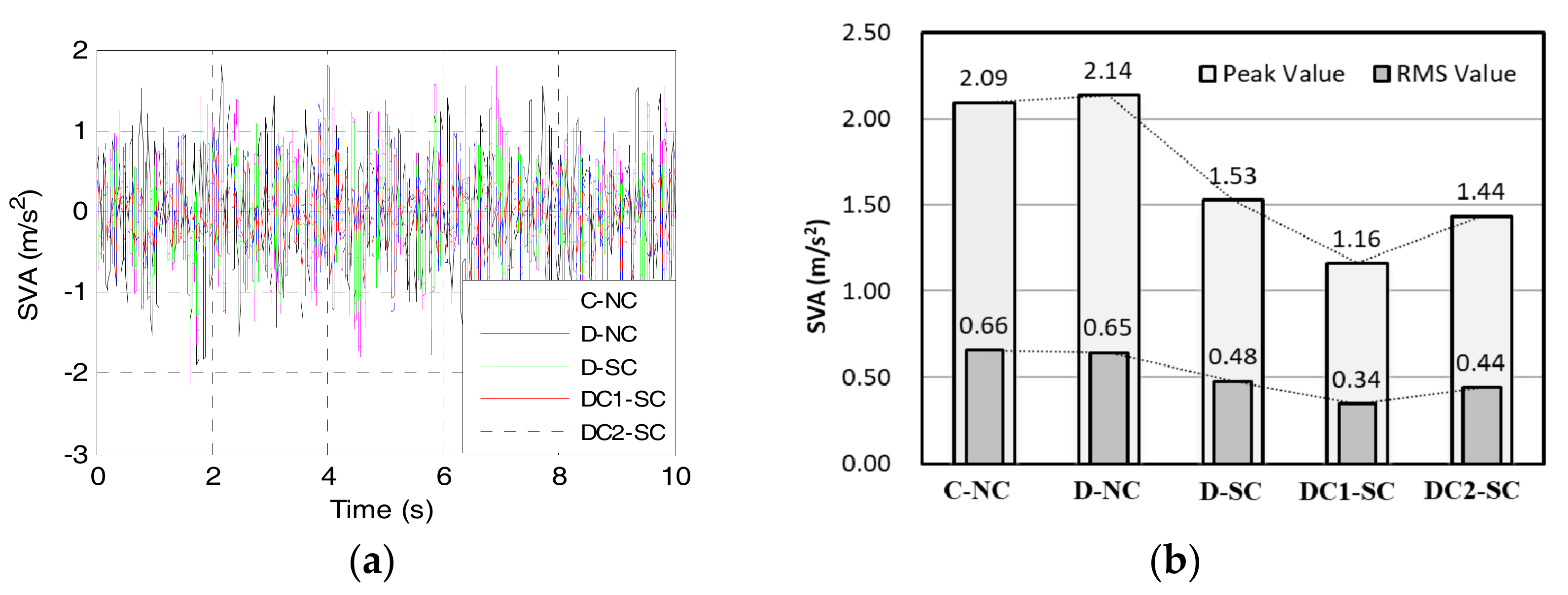
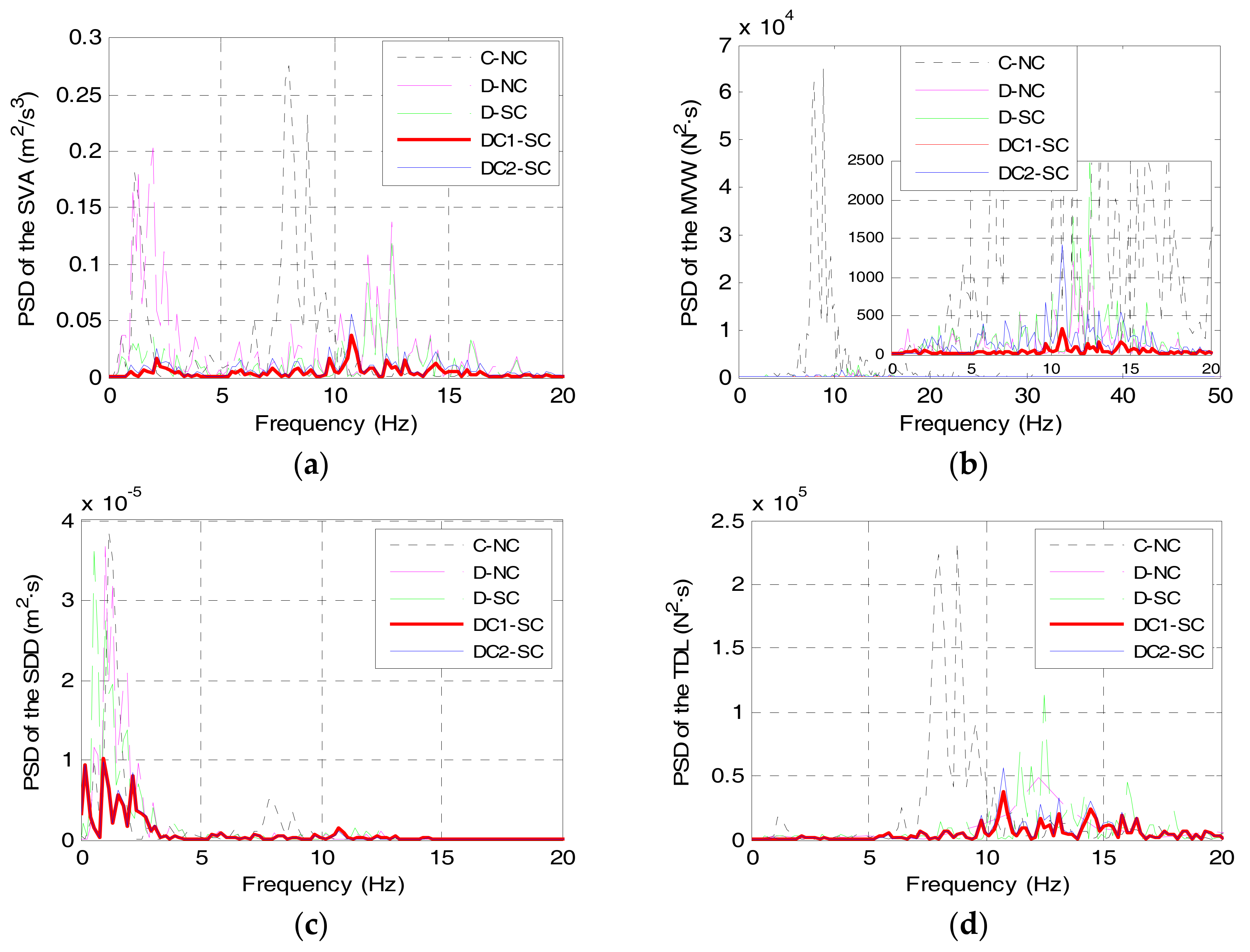
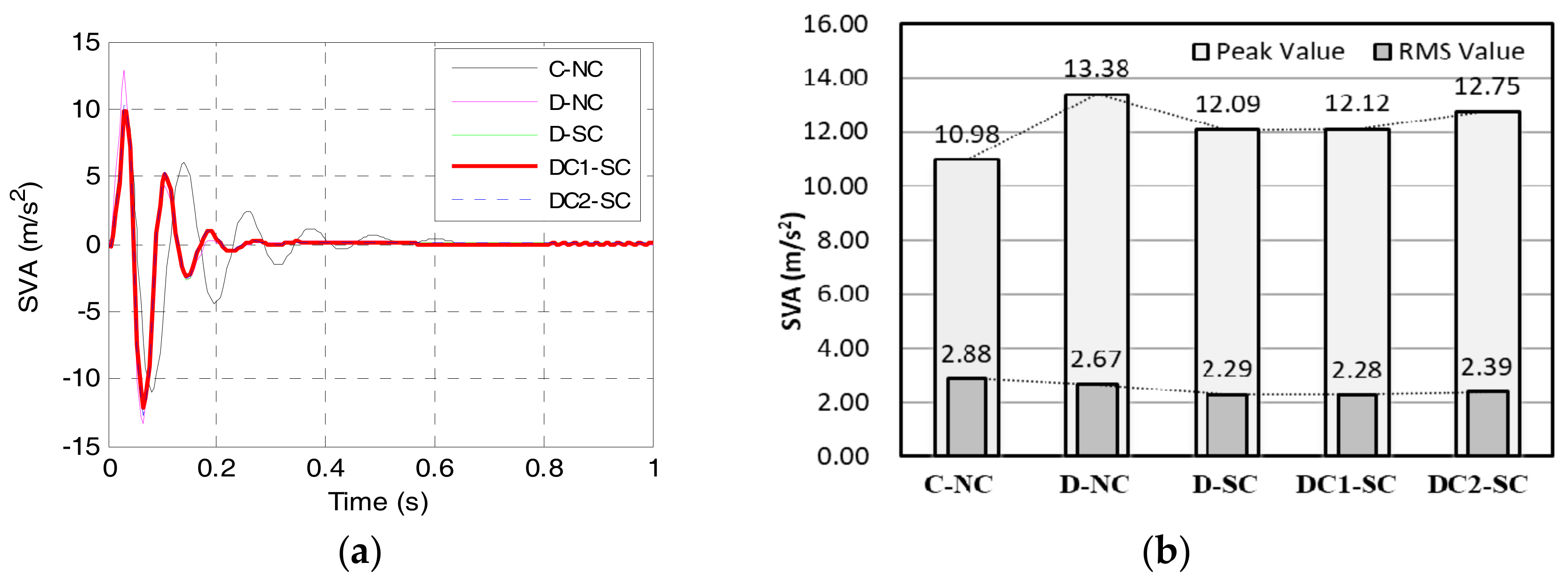
- Ride comfort. Vehicle ride comfort is mainly quantified by using the sprung mass vertical acceleration (SVA). Thus, the first optimization objective which should be minimized is the SVA, which is expressed as:
- (2)
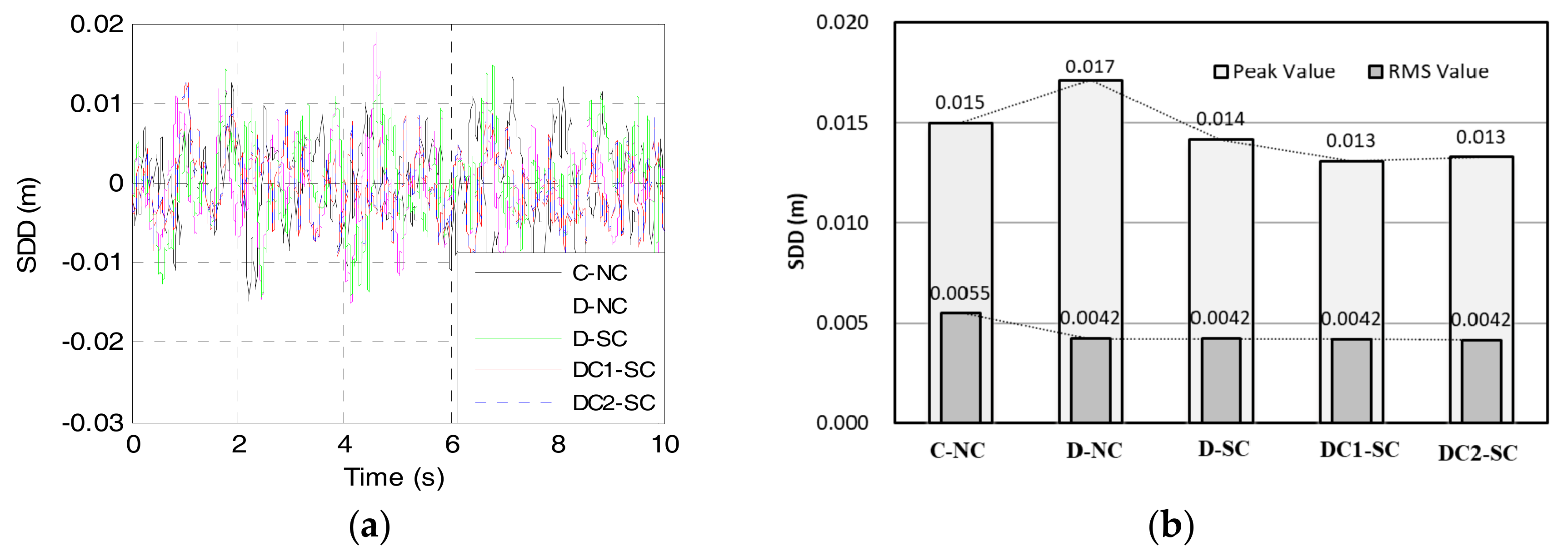
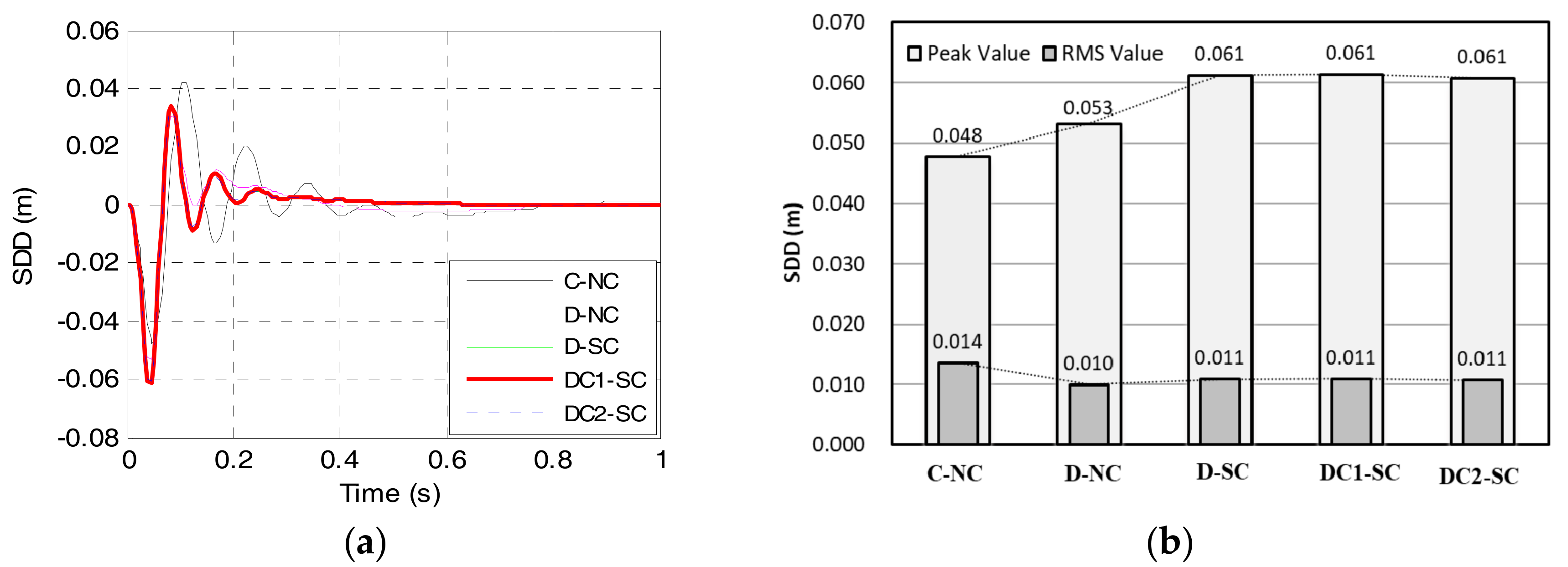
- Suspension deflection. The suspension dynamic deflection (SDD) should be constrained and not exceed its travel limit. That is:
- (3)
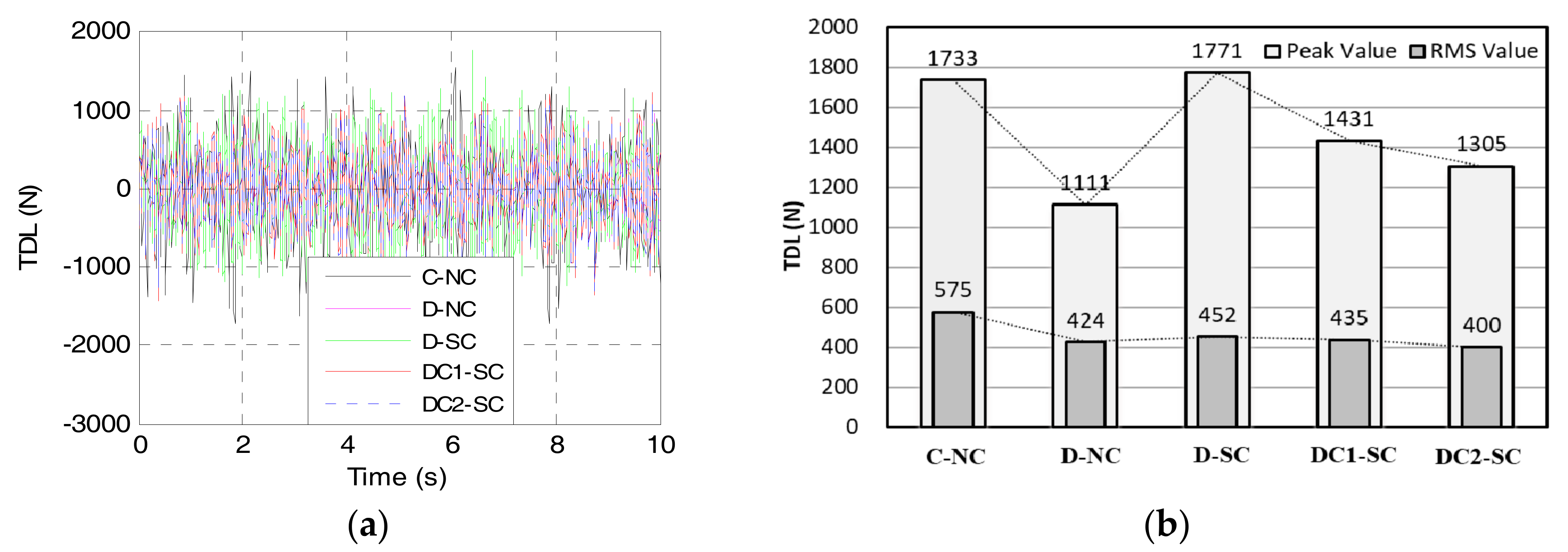
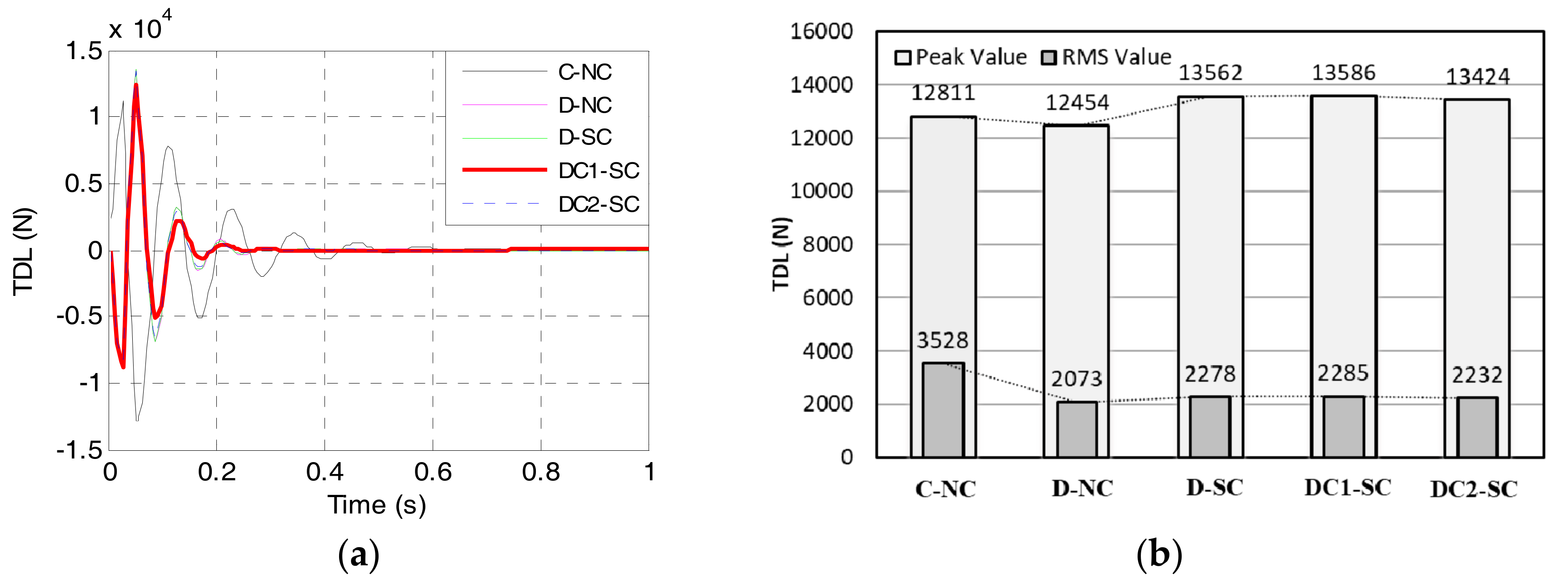
- Road holding. A firm uninterrupted contact of wheels to the road should be ensured to ensure the road holding and vehicle safety. Therefore, the tire dynamics load (TDL) should be minimized as well. The TDL is defines as:
- (4)
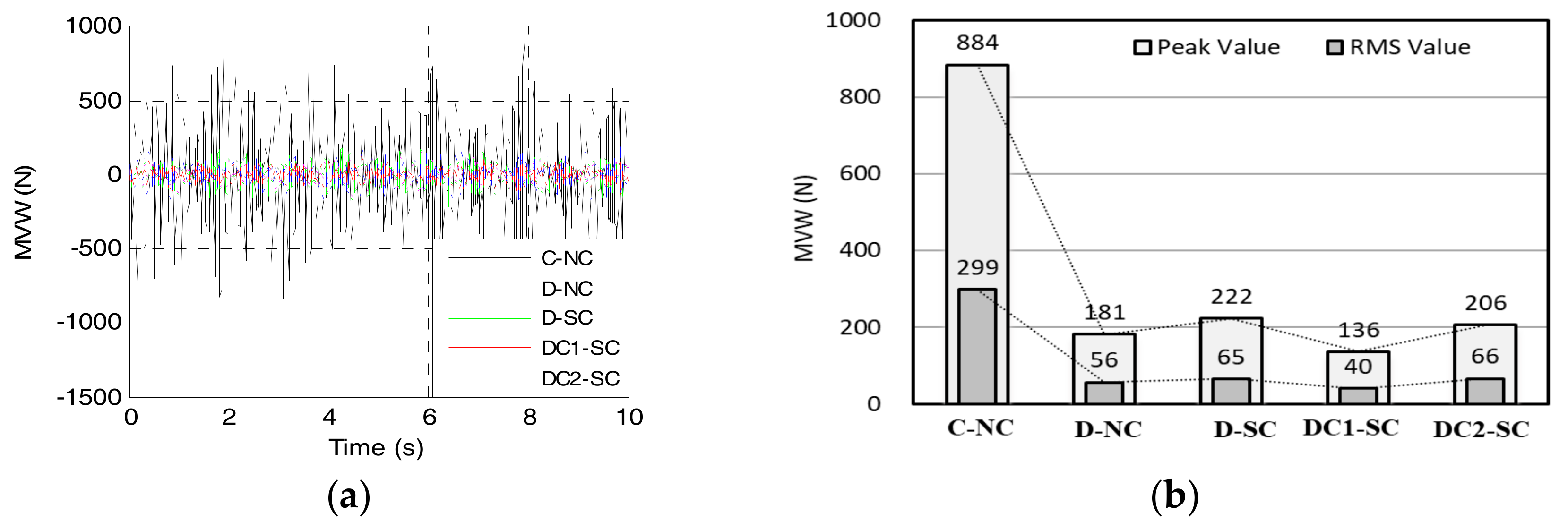
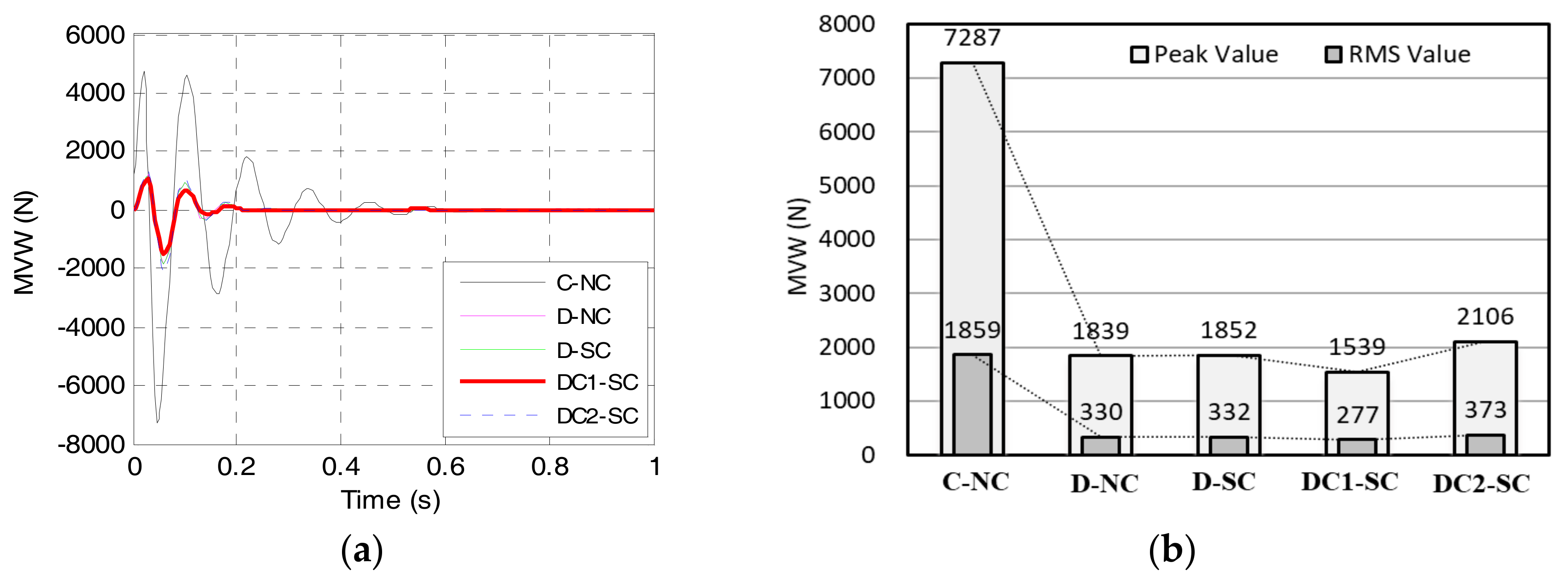
- IWM dynamic force. The IWM dynamic force can be quantified by using the motor vertical wallop (MVW), which should be suppressed to be as small as possible. The MVW is defined as
4. Coordination Control of the DVA and Suspension
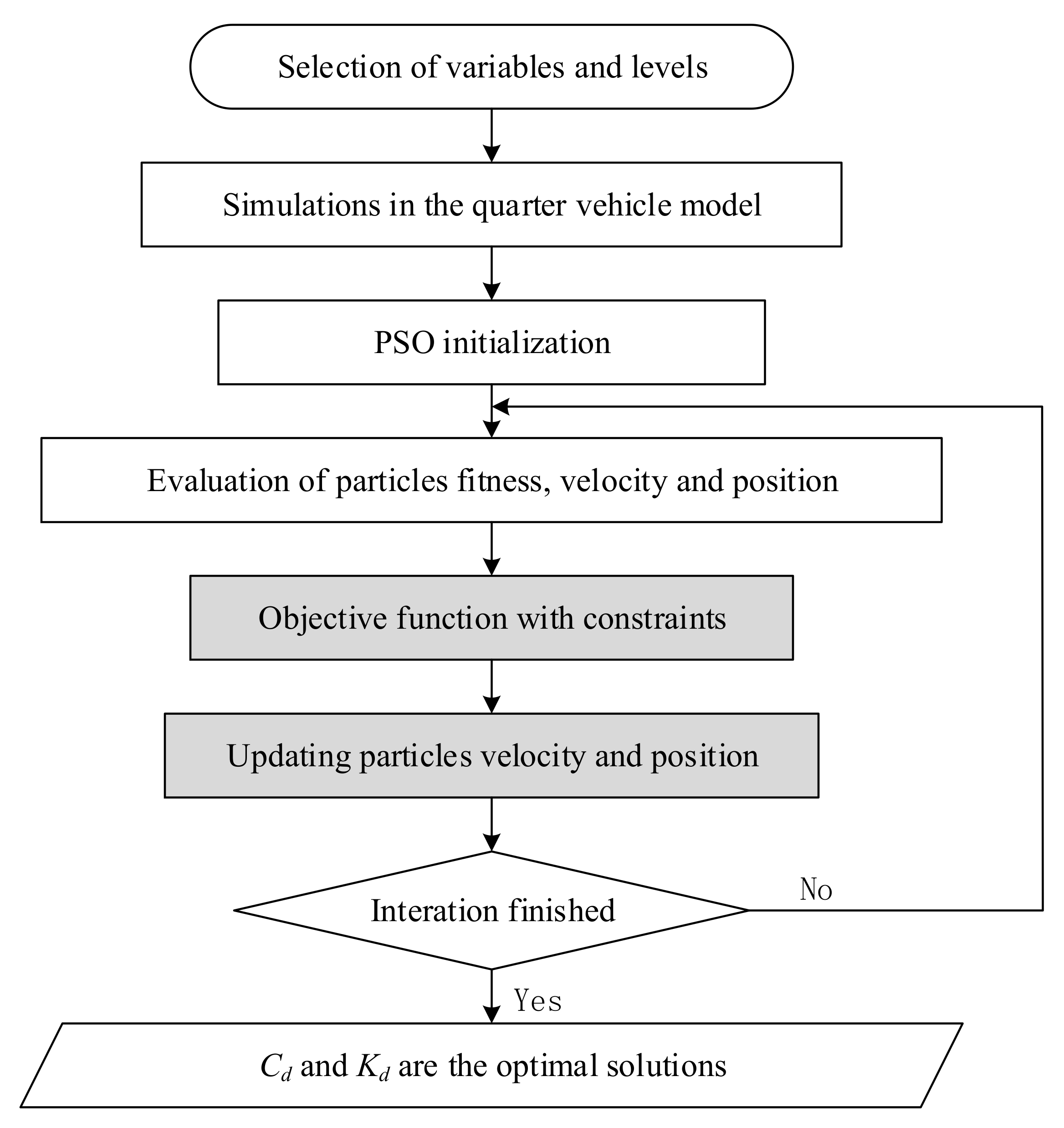
4.1. Parameters Optimization of the DVA
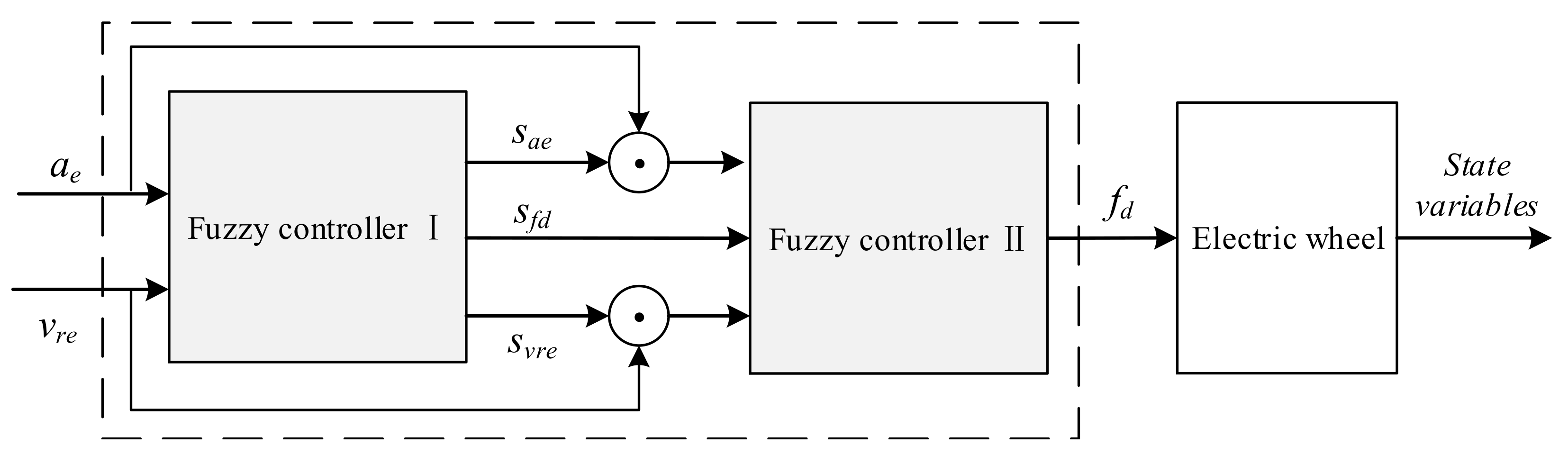
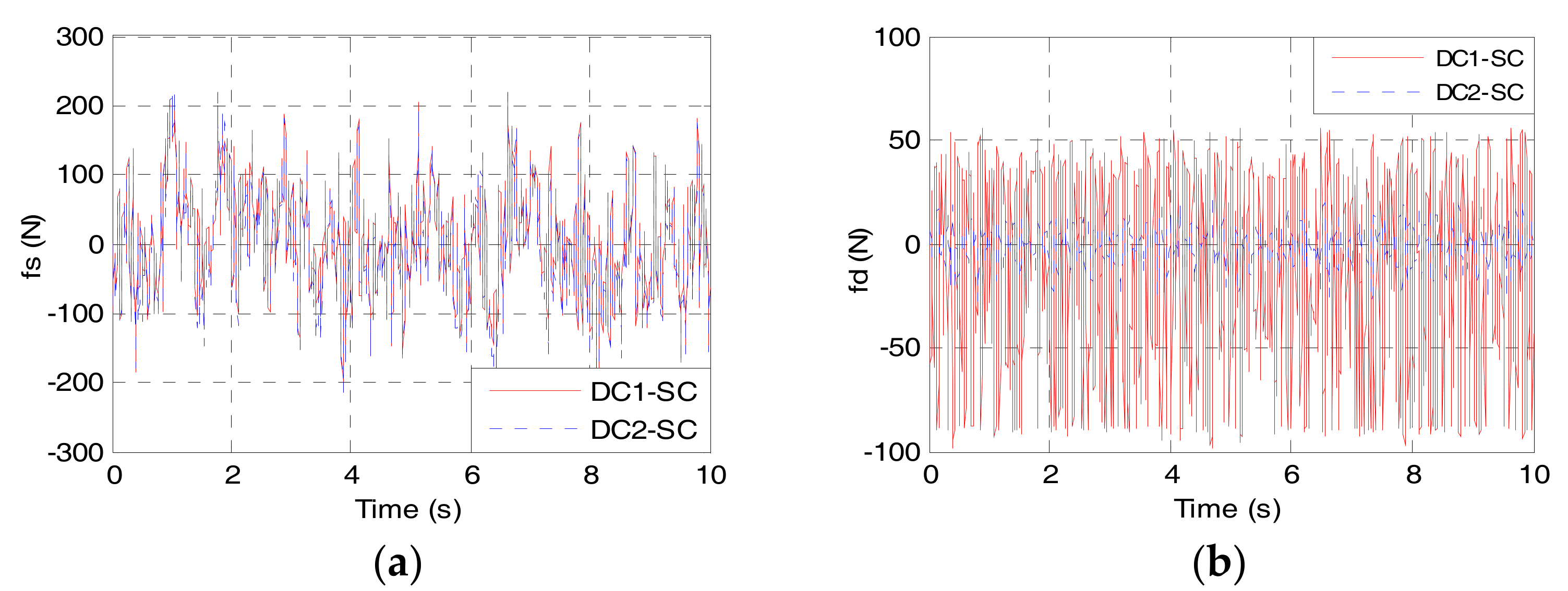
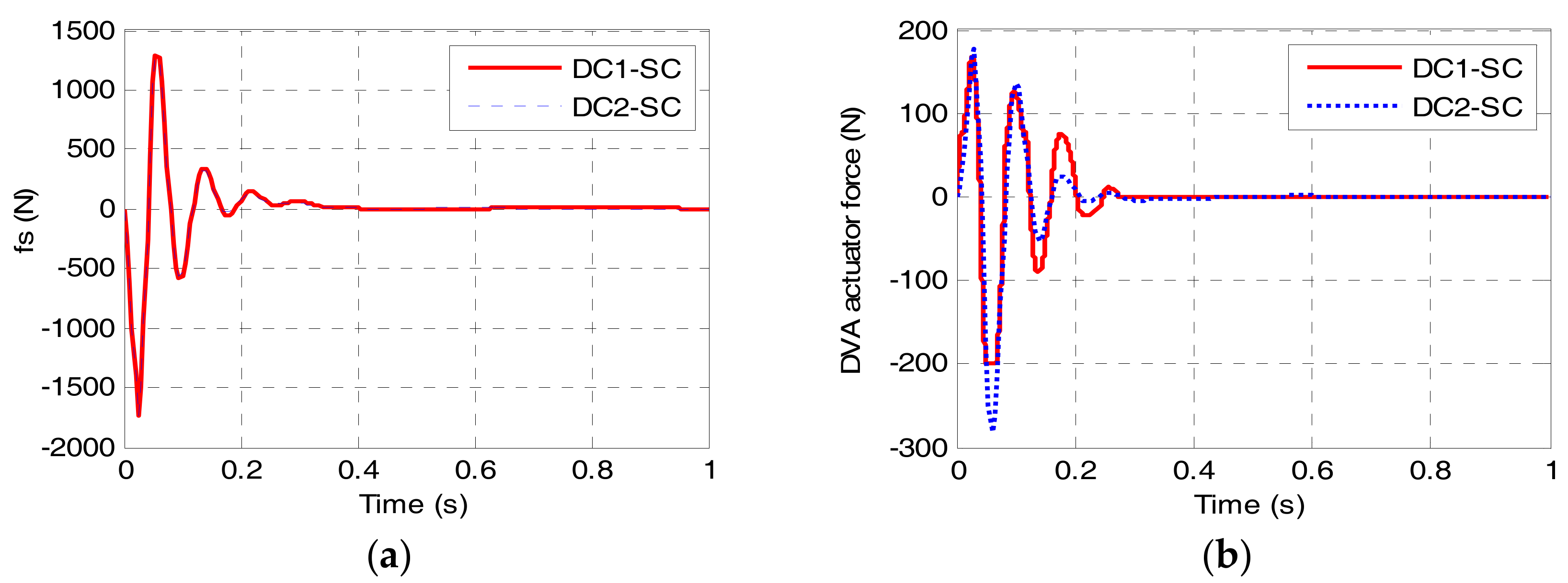
4.2. DVA Actuator Force Control
- (1)
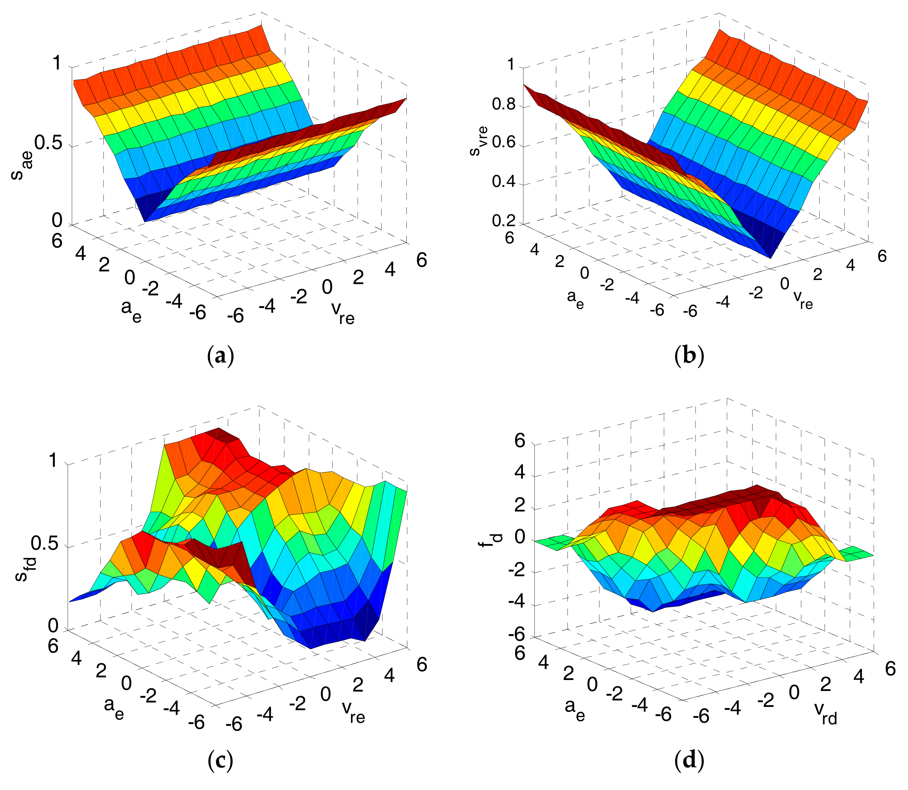
- The rules for the sae and svre are determined based on the ae and vre, respectively. Large values of the ae and vre correspond to large values of the sae and svre to enhance the control intensity and suppress the overshoot. Small values of the ae and vre correspond to small values of the sae and svre to narrow the domains and ensure the rule quantity, whereby the trade-off between the rule quantity and the control precision is well balanced.
- (2)
- The rules for the sfd are determined based on both the ae and vre. If both the ae and vre move in the same direction with large values, the sfd is set to a large value to suppress the vibration. If the ae and vre move in the opposite direction, the system is adaptive to gradually converge, so the sfd is set to a relatively small value. In addition, if the ae is a large value while the vre is a small value, the sfd is set to a relatively large value to prevent the system from the vibration divergence.
- (3)
- For the fuzzy controller I and II, the basic domains of the ae, vre, and fd are set to [−10, 10], [−2, 2] and [−200, 200], respectively, and their fuzzy domains are all set to [−6, 6]. In addition, the quantization factors are set to kae = 0.6, kvre = 3, and kfd = 33.
- (4)
- For the scaling factors, the basic domains of the sae, svre, and sfd are all set to [0, 1], and their fuzzy domains are set to [0, 1] as well.
- (5)
- The values of ae, vre, and fd are classed as seven fuzzy subsets, i.e., Positive Large (PL), Positive Medium (PM), Positive Small (PS), Zero (Z), Negative Small (NS), Negative Medium (NM), and Negative Large (NL).
- (6)
- The values of sae and svre are classed as four fuzzy subsets, Zero (Z), Small (S), Medium (M), and Large (L). While the values of sfd are classed as seven fuzzy subsets, Zero (Z), Very Small (VS), Small (S), Relatively Small (RS), Medium (M), Large (L), and Very Large (VL).
- (7)
- All fuzzy subsets’ membership functions are selected as triangular functions.
4.3. Suspension Actuator Force Control
5. Simulation Investigation
5.1. Simulation Parameters
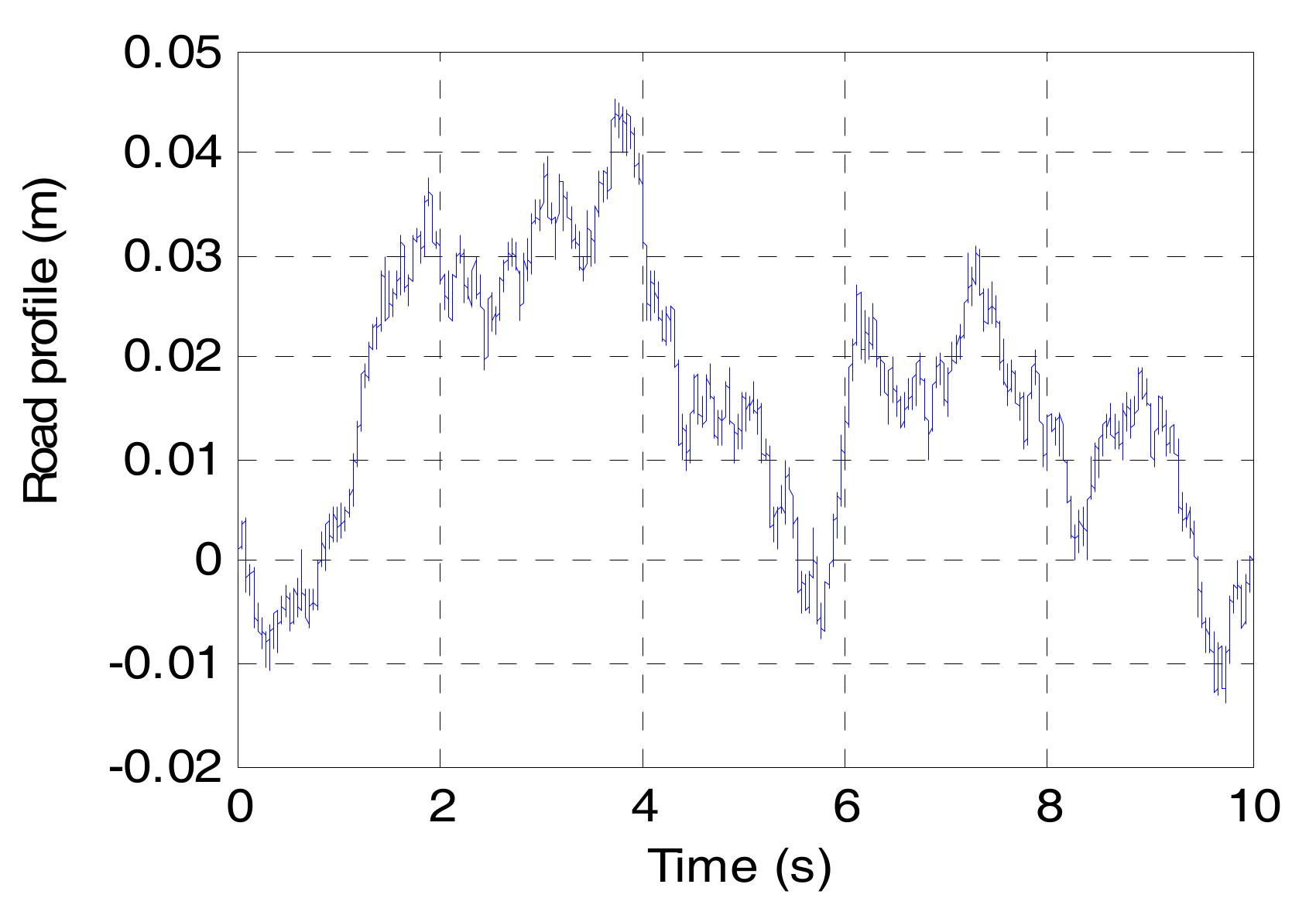
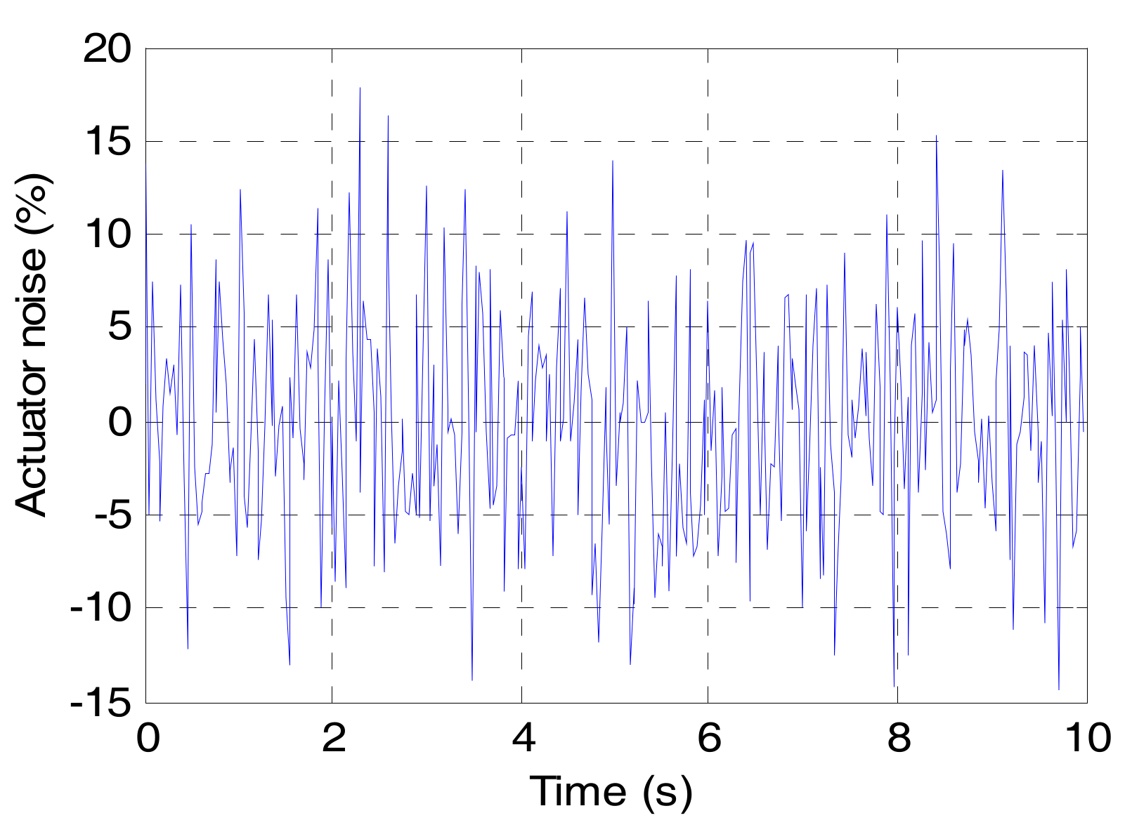
5.2. Random Road Excitation
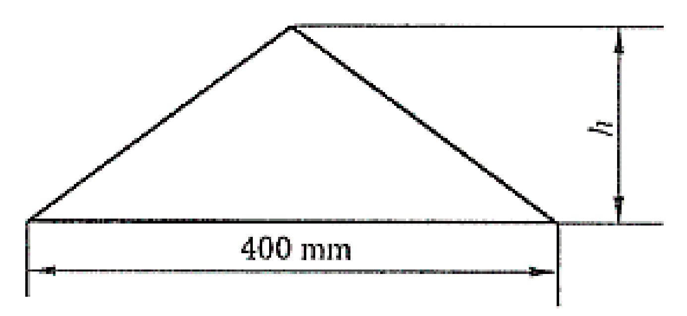
5.3. Bump Road Excitation
6. Conclusions
Acknowledgments
Author Contributions
Conflicts of Interest
References
- Sun, F.; Xiong, R.; He, H. A systematic state-of-charge estimation framework for multi-cell battery pack in electric vehicles using bias correction technique. Appl. Energy 2016, 162, 1399–1409. [Google Scholar] [CrossRef]
- Wu, X.; Hu, X.; Moura, S.; Yin, X.; Pickert, V. Stochastic control of smart home energy management with plug-in electric vehicle battery energy storage and photovoltaic array. J. Power Sources 2016, 333, 203–212. [Google Scholar] [CrossRef]
- Xiong, R.; Cao, J.; Yu, Q. Reinforcement learning-based real-time power management for hybrid energy storage system in the plug-in hybrid electric vehicle. Appl. Energy 2018, 211, 538–548. [Google Scholar] [CrossRef]
- Xiong, R.; Tian, J.; Mu, H.; Wang, C. A systematic model-based degradation behavior recognition and health monitoring method for lithium-ion batteries. Appl. Energy 2017, 207, 372–383. [Google Scholar] [CrossRef]
- Sachs, C.; Burandt, S.; Mandelj, S.; Mutter, R. Assessing the market of light electric vehicles as a potential application for electric in-wheel drives. In Proceedings of the 6th International Electric Drives Production Conference, Nuremberg, Germany, 30 November–1 December 2016. [Google Scholar]
- Xiong, R.; Zhang, Y.; He, H.; Zhou, X.; Pecht, M. A double-scale, particle-filtering, energy state prediction algorithm for lithium-ion batteries. IEEE Trans. Ind. Electron. 2017. [Google Scholar] [CrossRef]
- George, A.; Besselink, I. Rear suspension design for an in-wheel-drive electric car. J. Automob. Eng. 2016, 230, 147–159. [Google Scholar] [CrossRef]
- Wang, R.; Hu, C.; Yan, F.; Chadli, M. Composite Nonlinear Feedback Control for Path Following of Four-Wheel Independently Actuated Autonomous Ground Vehicles. IEEE Trans. Intell. Transp. Syst. 2016, 17, 2063–2074. [Google Scholar] [CrossRef]
- Hung, Y.; Wu, C. A combined optimal sizing and energy management approach for hybrid in-wheel motors of EVs. Appl. Energy 2015, 139, 260–271. [Google Scholar] [CrossRef]
- Zhang, G.; Zhang, H.; Huang, X.; Wang, J.; Yu, H.; Graaf, R. Active Fault-Tolerant Control for Electric Vehicles With Independently Driven Rear In-Wheel Motors Against Certain Actuator Faults. IEEE Trans. Control Syst. Technol. 2016, 24, 1557–1572. [Google Scholar] [CrossRef]
- Schalkwyk, D.; Kamper, M. Effect of Hub Motor Mass on Stability and Comfort of Electric Vehicles. In Proceedings of the 2006 IEEE Vehicle Power and Propulsion Conference, Windsor, UK, 1–6 September 2006. [Google Scholar]
- Murata, S. Innovation by in-wheel-motor drive unit. Veh. Syst. Dyn. 2012, 50, 807–830. [Google Scholar] [CrossRef]
- Wang, R.; Chen, Y.; Feng, D.; Huang, X.; Wang, J. Development and performance characterization of an electric ground vehicle with independently actuated in-wheel motors. J. Power Sources 2011, 196, 3962–3971. [Google Scholar]
- Katsuyama, E.; Omae, A. Improvement of Ride Comfort by Unsprung Negative Skyhook Damper Control Using In-Wheel Motors. SAE Int. J. Altern. Powertrains 2016, 5, 214–221. [Google Scholar] [CrossRef]
- Tokita, T.; Goto, H.; Ichinokura, O. An effect of Electromagnetic Force on Acoustic Noise of Axial-gap In-wheel SR Motor. In Proceedings of the 2014 International Conference on Electrical Machines (ICEM), Berlin, Germany, 2–5 September 2014. [Google Scholar]
- Tan, D.; Lu, C.; Zhang, X. Dual-loop PID control with PSO algorithm for the active suspension of the electric vehicle driven by in-wheel motor. J. Vibroeng. 2016, 18, 3915–3929. [Google Scholar] [CrossRef]
- Zhang, Y.; Chen, X.; Guo, K.; Zhang, X.; Li, S. Electro-hydraulic damper for energy harvesting suspension: Modeling, prototyping and experimental validation. Appl. Energy 2017, 199, 1–12. [Google Scholar] [CrossRef]
- Zhang, X.; Li, Z.; Guo, K.; Zheng, F.; Wang, Z. A novel pumping magnetorheological damper: Design, optimization, and evaluation. J. Intell. Mater. Syst. Struct. 2017, 28, 2339–2348. [Google Scholar]
- Bououden, S.; Chadli, M.; Karimi, H. A Robust Predictive Control Design for Nonlinear Active Suspension Systems. Asian J. Control. 2016, 18, 122–132. [Google Scholar] [CrossRef]
- Pepe, G.; Carcaterra, A. VFC-Variational Feedback Controller and its application to semi-active suspensions. Mech. Syst. Sig. Process. 2016, 76, 72–92. [Google Scholar] [CrossRef]
- Zhang, B.; Han, Q.; Zhang, X.; Yu, X. Sliding Mode Control With Mixed Current and Delayed States for Offshore Steel Jacket Platforms. IEEE Trans. Control Syst. Technol. 2014, 22, 1769–1783. [Google Scholar] [CrossRef]
- Zhang, B.; Han, Q.; Zhang, X. Recent advances in vibration control of offshore platforms. Nonlinear Dyn. 2017, 89, 755–771. [Google Scholar] [CrossRef]
- Jin, L.; Yu, Y.; Fu, Y. Study on the ride comfort of vehicles driven by in-wheel motors. Adv. Mech. Eng. 2016, 8, 9. [Google Scholar] [CrossRef]
- Jing, H.; Wang, R.; Li, C.; Wang, J.; Chen, N. Fault-tolerant control of active suspensions in in-wheel motor driven electric vehicles. Int. J. Veh. Des. 2015, 68, 22–36. [Google Scholar] [CrossRef]
- Shao, X.; Naghdy, F.; Du, H. Reliable fuzzy H-infinity control for active suspension of in-wheel motor driven electric vehicles with dynamic damping. Mech. Syst. Sig. Process. 2017, 87, 365–383. [Google Scholar] [CrossRef]
- Chen, C.; Xiong, R.; Shen, W. A Lithium-Ion Battery-in-the-Loop Approach to Test and Validate Multiscale Dual H Infinity Filters for State-of-Charge and Capacity Estimation. IEEE Trans. Power Electron. 2018, 33, 332–342. [Google Scholar] [CrossRef]
- Xiong, R.; Yu, Q.; Wang, L.; Lin, C. A novel method to obtain the open circuit voltage for the state of charge of lithium ion batteries in electric vehicles by using H infinity filter. Appl. Energy 2017, 207, 346–353. [Google Scholar] [CrossRef]
- Zhang, H.; Wang, J.M. Active Steering Actuator Fault Detection for an Automatically-Steered Electric Ground Vehicle. IEEE Trans. Veh. Technol. 2017, 66, 3685–3702. [Google Scholar] [CrossRef]
- Wang, R.; Zhang, H.; Wang, J. Linear Parameter-Varying Controller Design for Four-Wheel Independently Actuated Electric Ground Vehicles With Active Steering Systems. IEEE Trans. Control Syst. Technol. 2014, 22, 1281–1296. [Google Scholar]
- Tan, D.; Lu, C. The Influence of the Magnetic Force Generated by the In-Wheel Motor on the Vertical and Lateral Coupling Dynamics of Electric Vehicles. IEEE Trans. Veh. Technol. 2016, 65, 4655–4668. [Google Scholar] [CrossRef]
- Mao, Y.; Zuo, S.; Wu, X.; Duan, X. High frequency vibration characteristics of electric wheel system under in-wheel motor torque ripple. J. Sound Vib. 2017, 400, 442–456. [Google Scholar]
- Lehr, M.; Reis, K.; Binder, A. Comparison of axial flux and radial flux machines for the use in wheel hub drives. Elektrotech. Inf. 2015, 132, 25–32. [Google Scholar] [CrossRef]
- Takahashi, T.; Takemoto, M.; Ogasawara, S.; Hino, W.; Takezaki, K. Size and Weight Reduction of an In-Wheel Axial-Gap Motor Using Ferrite Permanent Magnets for Electric Commuter Cars. IEEE Trans. Ind. Appl. 2017, 53, 3927–3935. [Google Scholar] [CrossRef]
- Nikam, S.; Rallabandi, V.; Fernandes, B. A High-Torque-Density Permanent-Magnet Free Motor for in-Wheel Electric Vehicle Application. IEEE Trans. Ind. Appl. 2012, 48, 2287–2295. [Google Scholar] [CrossRef]
- Luo, Y.; Tan, D. Lightweight design of an in-wheel motor using the hybrid optimization method. J. Automob. Eng. 2013, 227, 1590–1602. [Google Scholar] [CrossRef]
- Luo, Y.; Tan, D. Study on the Dynamics of the In-Wheel Motor System. IEEE Trans. Veh. Technol. 2012, 61, 3510–3518. [Google Scholar]
- Tan, D.; Lu, C.; Ren, C. Optimal matching between the suspension and the rubber bushing of the in-wheel motor system. J. Automob. Eng. 2015, 229, 758–769. [Google Scholar] [CrossRef]
- Nagaya, G.; Wakao, Y.; Abe, A. Development of an in-wheel drive with advanced dynamic-damper mechanism. JSAE Rev. 2003, 24, 477–481. [Google Scholar] [CrossRef]
- Chen, X.; Yin, J.; Wang, W.; Wu, L.; Tang, F. Approaches to diminish large unsprung mass negative effects of wheel side drive electric vehicles. J. Adv. Mech. Design Syst. Manuf. 2016, 10, 17. [Google Scholar] [CrossRef]
- Wang, R.; Jing, H.; Yan, F.; Karimi, H.; Chen, N. Optimization and finite-frequency H-infinity control of active suspensions in in-wheel motor driven electric ground vehicles. J. Frankl. Inst. Eng. Appl. Math. 2015, 352, 468–484. [Google Scholar] [CrossRef]
- Ma, Y.; Deng, Z.; Xie, D. Control of the Active Suspension for In-Wheel Motor. J. Adv. Mech. Design Syst. Manuf. 2013, 7, 535–543. [Google Scholar] [CrossRef]
- Dezasse, M.; Ahmed, M.; Brembeck, J.; Svaricek, F. Experimental Evaluation of Linear Parameter-Varying Semi-Active Suspension Control. In Proceedings of the 2016 IEEE Conference on Control Applications, Buenos Aires, Argentina, 19–22 September 2016. [Google Scholar]
- Zhao, L.; Zhou, C.; Yu, Y. Damping Parameters Identification of Cabin Suspension System for Heavy Duty Truck Based on Curve Fitting. Shock Vib. 2016, 2016, 3051357. [Google Scholar]
- Marinakis, Y.; Migdalas, A.; Sifaleras, A. A hybrid Particle Swarm Optimization—Variable Neighborhood Search algorithm for Constrained Shortest Path problems. Eur. J. Oper. Res. 2017, 261, 819–834. [Google Scholar] [CrossRef]
- Liu, M.; Gu, F.; Zhang, Y. Ride Comfort Optimization of In-Wheel-Motor Electric Vehicles with In-Wheel Vibration Absorbers. Energies 2017, 10, 1647. [Google Scholar] [CrossRef]


| ae or vre | NL | NM | NS | Z | PS | PM | PL |
|---|---|---|---|---|---|---|---|
| sae or svre | L | M | S | Z | S | M | L |
| vre | ae | ||||||
|---|---|---|---|---|---|---|---|
| NL | NM | NS | Z | PS | PM | PL | |
| NL | VL | VL | L | L | M | S | VS |
| NM | VL | M | L | M | VS | S | VS |
| NS | S | RS | M | Z | M | RS | S |
| Z | VS | S | VS | M | L | M | VL |
| PS | VS | S | M | L | L | VL | VL |
| PM | Z | S | RS | VL | VL | VL | VL |
| PL | VL | VL | L | L | M | S | VS |
| vre | ae | ||||||
|---|---|---|---|---|---|---|---|
| NL | NM | NS | Z | PS | PM | PL | |
| NL | PL | PL | PL | PL | PM | Z | Z |
| NM | PL | PL | PL | PL | PM | Z | Z |
| NS | PM | PM | PM | PM | Z | NS | NS |
| Z | PM | PM | PS | Z | NM | NM | NM |
| PS | PS | PS | Z | NM | NM | NM | NM |
| PM | Z | Z | NM | NL | NL | NL | NL |
| PL | Z | Z | NM | NL | NL | NL | NL |
| Model Marked | Electric Wheel | DVA Control | Suspention Control |
|---|---|---|---|
| C-NC | Benchmarked Conventional | No control | No control |
| D-NC | DVA | No control | No control |
| D-SC | DVA | No control | LQR control |
| DC1-SC * | DVA | Fuzzy control with alterable domins | LQR control |
| DC2-SC ** | DVA | Fuzzy control with constant domins | LQR control |
| Parameters | C-NC | D-NC/D-SC/DC1-SC/DC2-SC * |
|---|---|---|
| sprung mass ms (kg) | 292 | 292 |
| Suspension stiffness Ks (N/m) | 17,000 | 17,000 |
| Suspension damping Cs (N·s/m) | 1317 | 1317 |
| Vertical stiffness of tire Kt (N/m) | 241,600 | 241,600 |
| Tire mass mt (kg) | 40 | 40 |
| Motor Mass me = me1 + me2 (kg) ** | 45 | 45 |
| suspension limited travel [ds] (m) | 0.08 | 0.08 |
| DVA spring stiffness Kd (N/m) | - | 8025 |
| DVA damping Cd (N·s/m) | - | 480 |
© 2017 by the authors. Licensee MDPI, Basel, Switzerland. This article is an open access article distributed under the terms and conditions of the Creative Commons Attribution (CC BY) license (http://creativecommons.org/licenses/by/4.0/).
Share and Cite
Liu, M.; Gu, F.; Huang, J.; Wang, C.; Cao, M. Integration Design and Optimization Control of a Dynamic Vibration Absorber for Electric Wheels with In-Wheel Motor. Energies 2017, 10, 2069. https://doi.org/10.3390/en10122069
Liu M, Gu F, Huang J, Wang C, Cao M. Integration Design and Optimization Control of a Dynamic Vibration Absorber for Electric Wheels with In-Wheel Motor. Energies. 2017; 10(12):2069. https://doi.org/10.3390/en10122069
Chicago/Turabian StyleLiu, Mingchun, Feihong Gu, Juhua Huang, Changjiang Wang, and Ming Cao. 2017. "Integration Design and Optimization Control of a Dynamic Vibration Absorber for Electric Wheels with In-Wheel Motor" Energies 10, no. 12: 2069. https://doi.org/10.3390/en10122069