
A High-Temperature Superconducting Bandpass Dual-Mode Filter with Tunable Relative Bandwidth and Center Frequency

Abstract
:1. Introduction
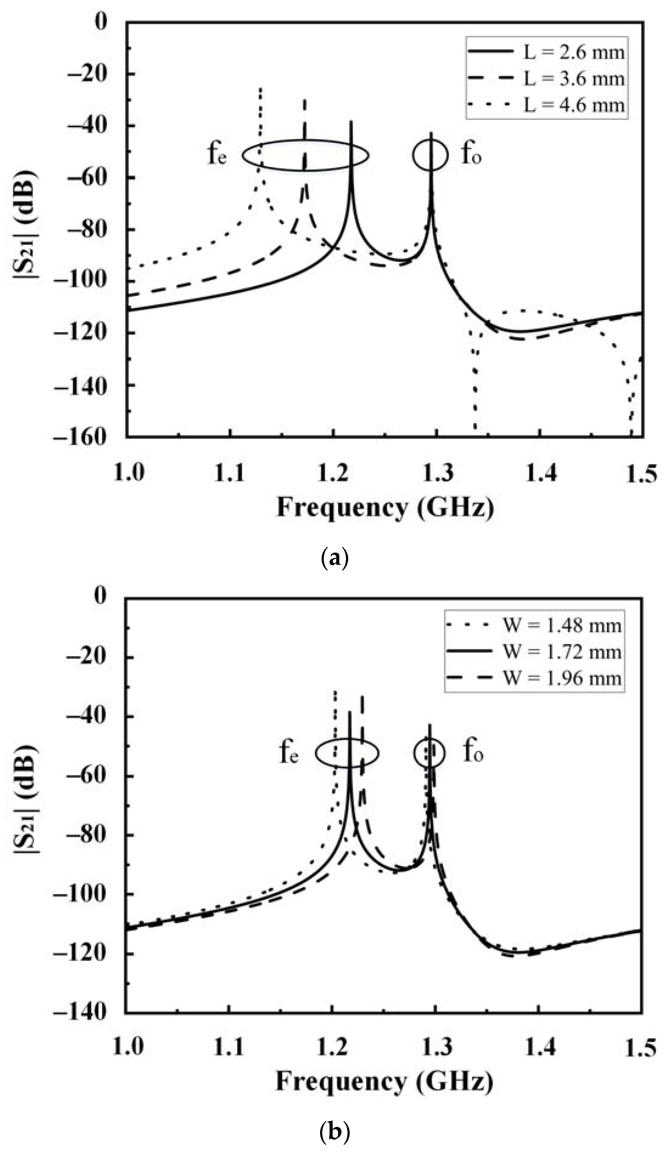
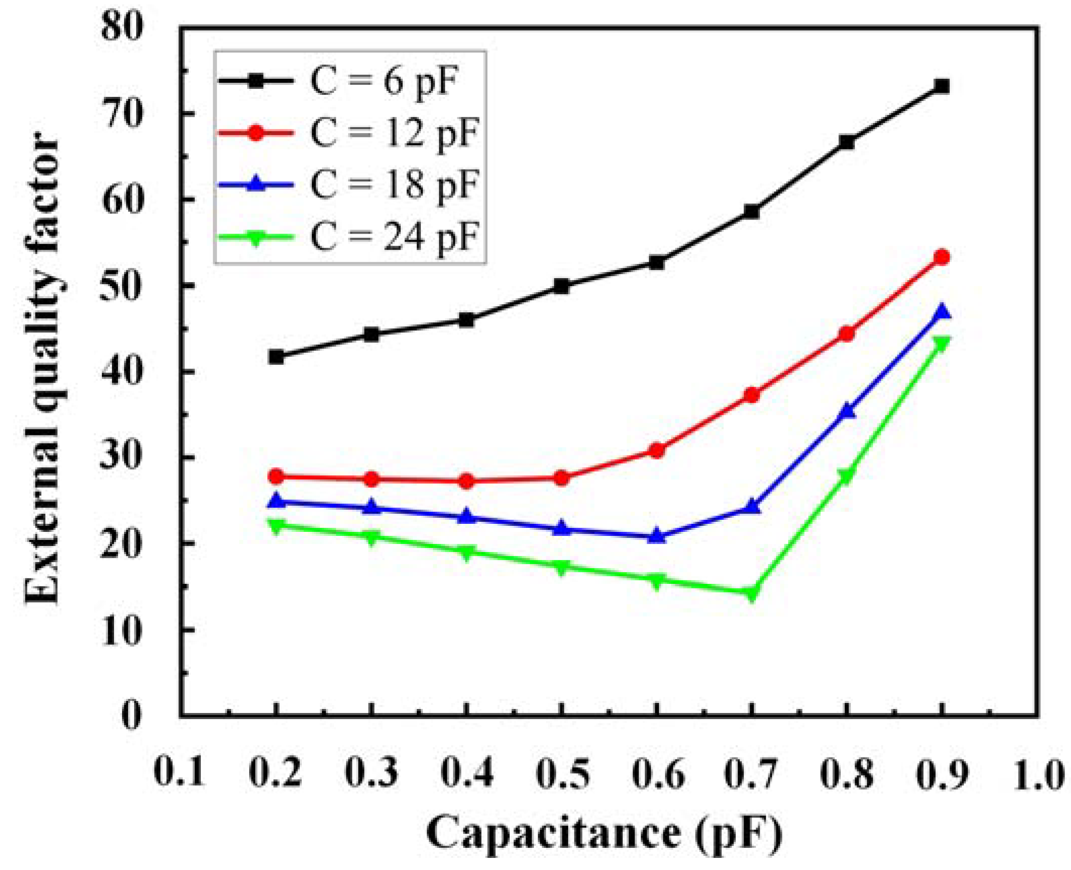
2. Analysis of DMRs
3. Design of a Four-Pole HTS-Tunable Filter
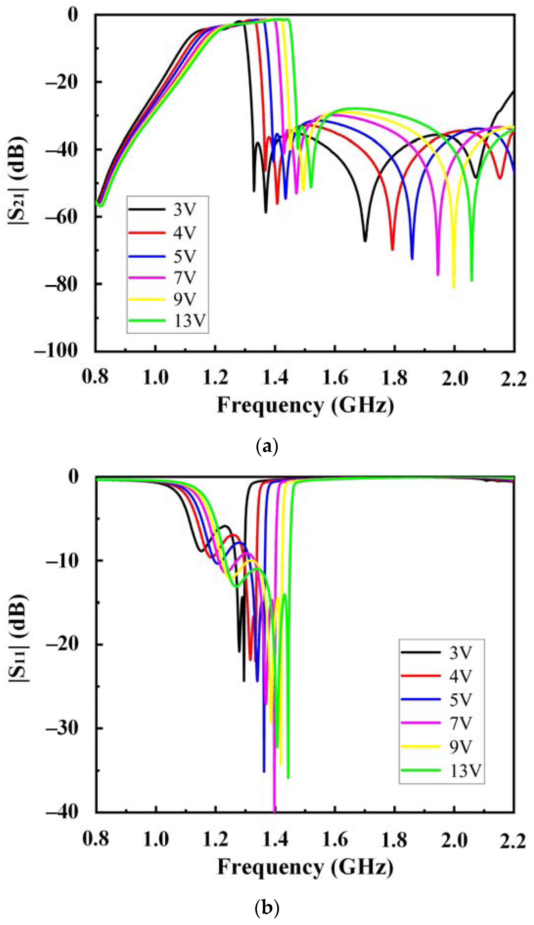
4. Simulation and Measurement Results
5. Conclusions
Author Contributions
Funding
Institutional Review Board Statement
Informed Consent Statement
Data Availability Statement
Acknowledgments
Conflicts of Interest
References
- Zhang, Q.; Zhu, F.; Zhou, H. Lumped-equivalent circuit model for multi-stage cascaded magnetoelectric dual-tunable bandpass filter. Chin. Phys. B 2015, 24, 107506. [Google Scholar] [CrossRef]
- Wu, D.; Wei, B.; Li, B.; Guo, X.; Lu, X.; Cao, B. Compact wide stopband superconducting bandpass filter using modified spiral resonators with interdigital structure. Chin. Phys. B 2018, 27, 068502. [Google Scholar] [CrossRef]
- Al-Yasir, Y.; Ojaroudi Parchin, N.; Tu, Y.; Abdulkhaleq, A.; Elfergani, I.; Rodriguez, J.; Abd-Alhameed, R. A Varactor-Based Very Compact Tunable Filter with Wide Tuning Range for 4G and Sub-6 GHz 5G Communications. Sensors 2020, 20, 4538. [Google Scholar] [CrossRef] [PubMed]
- Mao, J.; Choi, W.; Tam, K.; Che, W.; Xue, Q. Tunable bandpass filter design based on external quality factor tuning and multiple mode resonators for wideband applications. IEEE Trans. Microw. Theory Tech. 2013, 61, 2574–2584. [Google Scholar] [CrossRef]
- Chi, P.; Yang, T.; Tsai, T. A fully tunable two-pole bandpass filter. IEEE Microw. Wirel. Compon. Lett. 2015, 25, 292–294. [Google Scholar] [CrossRef]
- Zhang, Y.; Zhu, Y.; Meng, Z.; Zhang, J.; Zuo, K. A high stability fully tunable filter with frequency, bandwidth and transmission zero tuning. IEICE Electron. Express 2019, 16, 20190255. [Google Scholar] [CrossRef] [Green Version]
- Chen, A.; Yang, T. A microstrip bandpass filter with tunable bandwidth and center frequency. Microw. Opt. Technol. Lett. 2021, 63, 2333–2336. [Google Scholar] [CrossRef]
- Genc, A.; Baktur, R. A tunable bandpass filter based on varactor loaded split-ring resonators. Microw. Opt. Technol. Lett. 2009, 51, 2394–2396. [Google Scholar] [CrossRef]
- Suo, G.; Zhang, G.; Cao, B.; Guo, X.; Wei, B.; Zhang, X.; Feng, C.; Ying, Z.; Shang, Z. Design of continuously tunable superconducting filter with semiconductor varactors. Microw. Opt. Technol. Lett. 2014, 56, 775–777. [Google Scholar] [CrossRef]
- Zhao, F.; Ji, L.; Zhang, Z. A tunable broadband bandpass filter based on quarter wavelength resonators. Int. J. RF Microw. Comput. Aided Eng. 2021, 31, e22721. [Google Scholar] [CrossRef]
- Wang, X.; Wang, J.; Li, C.; Wu, Y.; Zhang, X.; Dai, J.; Yuan, Y.; Zhang, C.; He, Y.; Sun, L. A Compact Four-Pole Tunable HTS Bandpass Filter at VHF Band. IEEE Trans. Appl. Supercond. 2021, 31, 1501207. [Google Scholar] [CrossRef]
- Ying, Z.; Wei, B.; Cao, B.; Guo, X.; Zhang, X.; Zhang, G.; Li, Q.; Feng, C. An Ultra-Low Loss 2B Reconfigurable Superconducting Filter at P-Band. IEEE Microw. Wirel. Compon. Lett. 2013, 23, 19–21. [Google Scholar] [CrossRef]
- Suo, G.; Guo, X.; Cao, B.; Wei, B.; Zhang, X.; Shang, Z.; Zhang, G. Low Loss Tunable Superconducting Dual-Mode Filter at L-Band Using Semiconductor Varactors. IEEE Microw. Wirel. Compon. Lett. 2014, 24, 170–172. [Google Scholar] [CrossRef]
- Li, C.; Wang, J.; Bian, Y.; Li, G.; Wu, Y.; Zhang, Q.; Li, N.; Wang, X.; Zhang, X.; Sun, L.; et al. A tunable high temperature superconducting bandpass filter using semiconductor varactors. In Proceedings of the 2013 IEEE 14th International Superconductive Electronics Conference (ISEC), Cambridge, MA, USA, 07–11 July 2013; pp. 1–3. [Google Scholar]
- Tang, W.; Hong, J. Microstrip quasi-elliptic function bandpass filter with improved tuning range. In Proceedings of the 2010 40th European Microwave Conference, Paris, France, 28–30 September 2010; pp. 751–754. [Google Scholar]
- Chiou, Y.; Rebeiz, G. Tunable 1.55–2.1 GHz 4-Pole elliptic bandpass filter with bandwidth control and >50 dB rejection for wireless systems. IEEE Trans. Microw. Theory Tech. 2013, 61, 117–124. [Google Scholar] [CrossRef]
- Li, C.; Bian, Y.; Li, G.; Wu, Y.; Wang, J.; Wang, X.; Zhang, X.; Xia, F.; Bai, D.; Sun, L.; et al. A Tunable High Temperature Superconducting Bandpass Filter Realized Using Semiconductor Varactors. IEEE Trans. Appl. Supercond. 2014, 24, 1501205. [Google Scholar] [CrossRef]
- Kumar, A.; Pathak, N. Varactor-incorporated bandpass filter with reconfigurable frequency and bandwidth. Microw. Opt. Technol. Lett. 2017, 59, 2083–2089. [Google Scholar] [CrossRef]


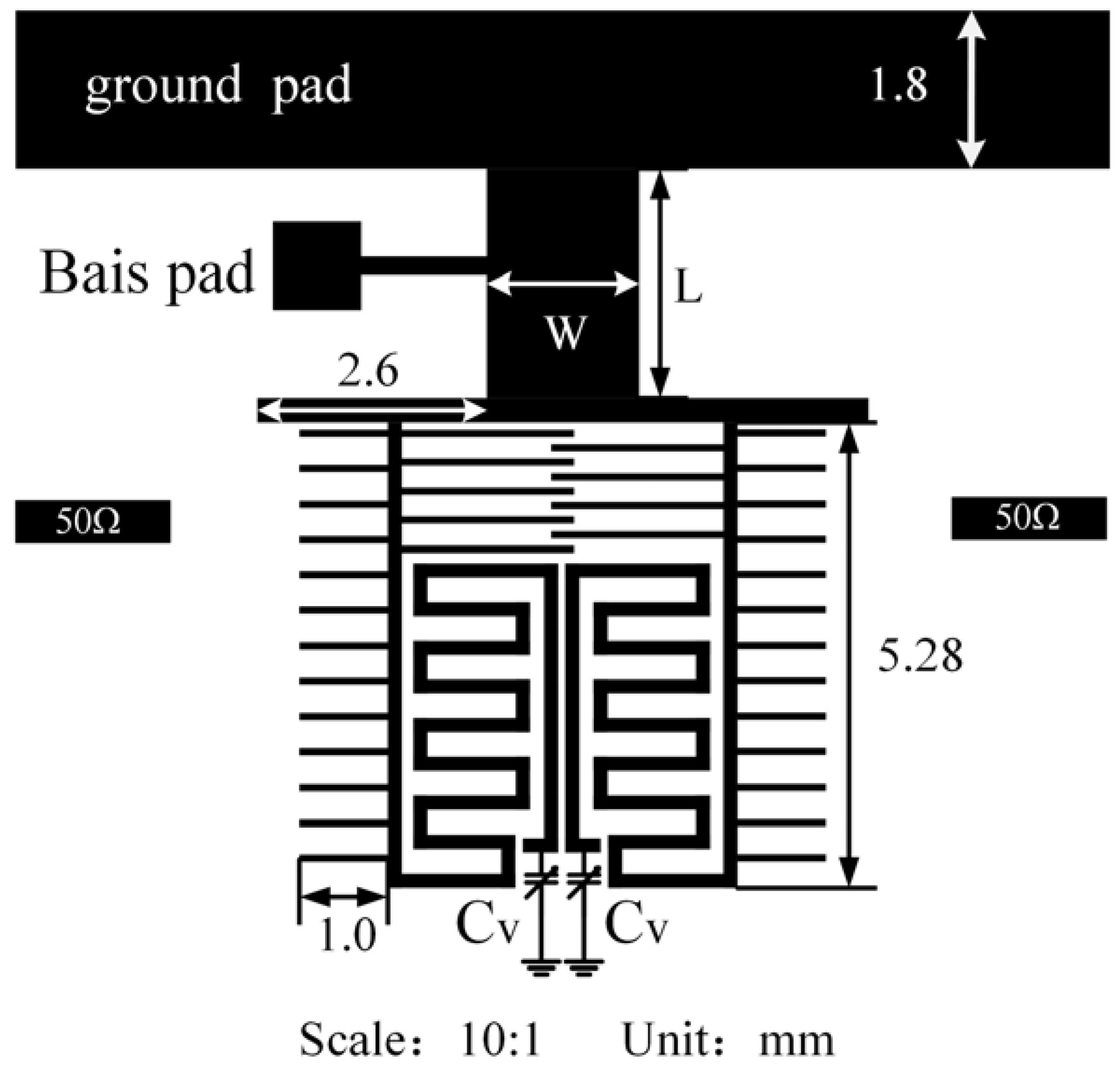
| Parameters | W | W1 | W2 | L | L1 | L2 | L3 | g |
|---|---|---|---|---|---|---|---|---|
| Dimensions (mm) | 1.72 | 0.68 | 0.28 | 2.6 | 4.08 | 0.72 | 1.48 | 1.92 |
| No. | Bias Voltage/V | Frequency /GHz | 3-dB Bandwidth /MHz | Insertion Loss/dB |
|---|---|---|---|---|
| 1 | 3 | 1.22 | 158 | 3.59 |
| 2 | 4 | 1.25 | 175 | 3.50 |
| 3 | 5 | 1.27 | 189 | 3.10 |
| 4 | 7 | 1.30 | 208 | 2.64 |
| 5 | 9 | 1.32 | 219 | 2.42 |
| 6 | 13 | 1.34 | 233 | 2.28 |
| Ref. | Filter Order | Tuning Range/MHz | C /pF | Insertion Loss/dB | 3-dB Fractional Bandwidth |
|---|---|---|---|---|---|
| [15] [16] | 4 | 830–1010 | 2.7–3.3 | 3–4 | 3–3.6% |
| 4 | 1550–2100 | 0.45–2.5 | 4–6.5 | 2.2–8% (1 dB) | |
| [17] | 4, HTS | 430–720 | 0.5–20 | 0.8–3.8 | 2.8–3.2% |
| [5] | 2 | 1700–2700 | 0.3–2.4 | 3.8–4.9 | 2.9–6.5% (1 dB) |
| [18] | 4 | 3750–4000 | 0.72–4.15 | <6 dB | 3.5–7% |
| [11] | 4, HTS | 73.2–118 | 1–21 | 0.6–2.2 | 3.2–4.3% |
| this work | 4, HTS | 1220–1340 | 0.2–0.9 | 2.28–3.59 | 12.95–17.39% |
Disclaimer/Publisher’s Note: The statements, opinions and data contained in all publications are solely those of the individual author(s) and contributor(s) and not of MDPI and/or the editor(s). MDPI and/or the editor(s) disclaim responsibility for any injury to people or property resulting from any ideas, methods, instructions or products referred to in the content. |
© 2023 by the authors. Licensee MDPI, Basel, Switzerland. This article is an open access article distributed under the terms and conditions of the Creative Commons Attribution (CC BY) license (https://creativecommons.org/licenses/by/4.0/).
Share and Cite
Shang, Z.; Shen, L.; Huang, J.; Zhang, H. A High-Temperature Superconducting Bandpass Dual-Mode Filter with Tunable Relative Bandwidth and Center Frequency. Sensors 2023, 23, 1079. https://doi.org/10.3390/s23031079
Shang Z, Shen L, Huang J, Zhang H. A High-Temperature Superconducting Bandpass Dual-Mode Filter with Tunable Relative Bandwidth and Center Frequency. Sensors. 2023; 23(3):1079. https://doi.org/10.3390/s23031079
Chicago/Turabian StyleShang, Zhaojiang, Liejun Shen, Jianyong Huang, and Huibin Zhang. 2023. "A High-Temperature Superconducting Bandpass Dual-Mode Filter with Tunable Relative Bandwidth and Center Frequency" Sensors 23, no. 3: 1079. https://doi.org/10.3390/s23031079