
Influence of Annealing on Polymer Optical Fiber Bragg Grating Inscription, Stability and Sensing: A Review
 , ,
, , 
Abstract
:1. Introduction
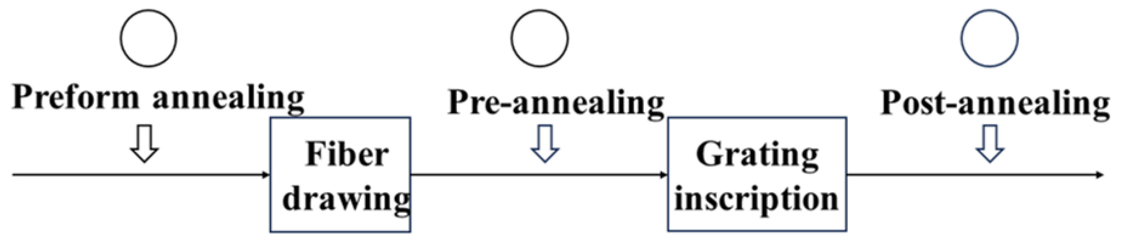
2. Timing of Annealing
3. Annealing Conditions
3.1. Temperature
3.2. Humidity
3.3. Strain and Stress
3.4. Chemical Treatment
4. Inscription of POFBG
4.1. Fiber Bragg Gratings
4.2. FBG Inscription Method in POFs
5. Annealing Influence on POFBGS
5.1. POF Properties
5.2. POFBG Inscription Time
5.3. Grating Reflectivity
5.4. Hysteresis
5.5. Linear Temperature Range
5.6. Bragg Wavelength
6. Annealing Influence on Grating Sensitivity
6.1. Grating Humidity Sensor
6.2. Grating Temperature Sensor
6.3. Grating Strain, Stress and Force Sensors
7. Conclusions
Author Contributions
Funding
Institutional Review Board Statement
Informed Consent Statement
Data Availability Statement
Conflicts of Interest
References
- Webb, D.J. Fibre Bragg Grating Sensors in Polymer Optical Fibres. Meas. Sci. Technol. 2015, 26, 092004. [Google Scholar] [CrossRef]
- He, R.; Teng, C.; Kumar, S.; Marques, C.; Min, R. Polymer Optical Fiber Liquid Level Sensor: A Review. IEEE Sens. J. 2022, 22, 1081–1091. [Google Scholar] [CrossRef]
- Peters, K. Polymer Optical Fiber Sensors—A Review. Smart Mater. Struct. 2010, 20, 013002. [Google Scholar] [CrossRef]
- Ziemann, O.; Krauser, J.; Zamzow, P.E.; Daum, W. POF Handbook-Optical Short Range Transmission Systems; Springer: Berlin, Germany, 2008; ISBN 978-3-540-76628-5. [Google Scholar]
- Large, M.C.J.; Blacket, D.; Bunge, C.-A. Microstructured Polymer Optical Fibers Compared to Conventional POF: Novel Properties and Applications. IEEE Sens. J. 2010, 10, 1213–1217. [Google Scholar] [CrossRef]
- Soge, A.O.; Dairo, O.F.; Sanyaolu, M.E.; Kareem, S.O. Recent Developments in Polymer Optical Fiber Strain Sensors: A Short Review. J. Opt. 2021, 50, 299–313. [Google Scholar] [CrossRef]
- Leal-Junior, A.G.; Diaz, C.A.R.; Avellar, L.M.; Pontes, M.J.; Marques, C.; Frizera, A. Polymer Optical Fiber Sensors in Healthcare Applications: A Comprehensive Review. Sensors 2019, 19, 3156. [Google Scholar] [CrossRef] [PubMed]
- Xiong, Z.; Peng, G.D.; Wu, B.; Chu, P.L. Highly Tunable Bragg Gratings in Single-Mode Polymer Optical Fibers. IEEE Photonics Technol. Lett. 1999, 11, 352–354. [Google Scholar] [CrossRef]
- Dobb, H.; Webb, D.J.; Kalli, K.; Argyros, A.; Large, M.C.J.; van Eijkelenborg, M.A. Continuous Wave Ultraviolet Light-Induced Fiber Bragg Gratings in Few- and Single-Mode Microstructured Polymer Optical Fibers. Opt. Lett. 2005, 30, 3296–3298. [Google Scholar]
- Johnson, I.P.; Yuan, W.; Stefani, A.; Nielsen, K.; Rasmussen, H.K.; Khan, L.; Webb, D.J.; Kalli, K.; Bang, O. Optical Fibre Bragg Grating Recorded in TOPAS Cyclic Olefin Copolymer. Electron. Lett. 2011, 47, 271–272. [Google Scholar] [CrossRef]
- Woyessa, G.; Rasmussen, H.K.; Bang, O. Zeonex—A Route towards Low Loss Humidity Insensitive Single-Mode Step-Index Polymer Optical Fibre—ScienceDirect. Opt. Fiber Technol. 2020, 57, 102231. [Google Scholar] [CrossRef]
- Cheng, X.; Gunawardena, D.S.; Pun, C.-F.J.; Bonefacino, J.; Tam, H.-Y. Single Nanosecond-Pulse Production of Polymeric Fiber Bragg Gratings for Biomedical Applications. Opt. Express 2020, 28, 33573–33583. [Google Scholar] [CrossRef] [PubMed]
- Woyessa, G.; Fasano, A.; Markos, C.; Rasmussen, H.K.; Bang, O. Low Loss Polycarbonate Polymer Optical Fiber for High Temperature FBG Humidity Sensing. IEEE Photonics Technol. Lett. 2017, 29, 575–578. [Google Scholar] [CrossRef]
- Theodosiou, A.; Kalli, K. Recent Trends and Advances of Fibre Bragg Grating Sensors in CYTOP Polymer Optical Fibres. Opt. Fiber Technol. 2020, 54, 102079. [Google Scholar] [CrossRef]
- Zhang, W.; Webb, D.J. Factors Influencing the Temperature Sensitivity of PMMA Based Optical Fiber Bragg Gratings. In Proceedings of the Micro-Structured and Specialty Optical Fibres III, Brussels, Belgium, 2 May 2014; SPIE: Bellingham, WA, USA, 2014; Volume 9128, pp. 108–114. [Google Scholar]
- Pospori, A.; Marques, C.a.F.; Zubel, M.G.; Sáez-Rodríguez, D.; Nielsen, K.; Bang, O.; Webb, D.J. Annealing Effects on Strain and Stress Sensitivity of Polymer Optical Fibre Based Sensors. In Proceedings of the Micro-Structured and Specialty Optical Fibres IV, Brussels, Belgium, 27 April 2016; SPIE: Bellingham, WA, USA, 2016; Volume 9886, pp. 126–132. [Google Scholar]
- Argyros, A. Microstructured Polymer Optical Fibers. J. Light. Technol. 2009, 27, 1571–1579. [Google Scholar] [CrossRef]
- Koike, Y.; Asai, M. The Future of Plastic Optical Fiber. NPG Asia Mater. 2009, 1, 22–28. [Google Scholar] [CrossRef]
- Koike, Y.; Ishigure, T. Progress of Low-Loss GI Polymer Optical Fiber from Visible to 1.5-/Spl Mu/m Wavelength. In Proceedings of the Integrated Optics and Optical Fibre Communications, 11th International Conference on, and 23rd European Conference on Optical Communications (Conf. Publ. No.: 448), Edinburgh, UK, 22–25 September 1997; Volume 1, pp. 59–62. [Google Scholar]
- Ishigure, T.; Hirai, M.; Sato, M.; Koike, Y. Graded-Index Plastic Optical Fiber with High Mechanical Properties Enabling Easy Network Installations. I. J. Appl. Polym. Sci. 2004, 91, 404–409. [Google Scholar] [CrossRef]
- Peng, G.D.; Xiong, Z.; Chu, P.L. Photosensitivity and Gratings in Dye-Doped Polymer Optical Fibers. Opt. Fiber Technol. 1999, 5, 242–251. [Google Scholar] [CrossRef]
- Othonos, A.S.; Lee, X. Novel and Improved Methods of Writing Bragg Gratings with Phase Masks. IEEE Photonics Technol. Lett. 1995, 7, 1183–1185. [Google Scholar] [CrossRef]
- Singh, N.; Jain, S.C.; Aggarwal, A.K.; Bajpai, R.P. Fibre Bragg Grating Writing Using Phase Mask Technology. J. Sci. Ind. Res. 2005, 64, 108–115. [Google Scholar]
- Suo, R.; Lousteau, J.; Li, H.; Jiang, X.; Zhou, K.; Zhang, L.; MacPherson, W.N.; Bookey, H.T.; Barton, J.S.; Kar, A.K.; et al. Fiber Bragg Gratings Inscribed Using 800nm Femtosecond Laser and a Phase Mask in Single-and Multi-Core Mid-IR Glass Fibers. Opt. Express 2009, 17, 7540–7548. [Google Scholar] [CrossRef]
- Mihailov, S.J.; Smelser, C.W.; Lu, P.; Walker, R.B.; Grobnic, D.; Ding, H.; Henderson, G.; Unruh, J. Fiber Bragg Gratings Made with a Phase Mask and 800-Nm Femtosecond Radiation. Opt. Lett. 2003, 28, 995–997. [Google Scholar] [CrossRef] [PubMed]
- Maselli, V.; Grenier, J.R.; Ho, S.; Herman, P.R. Femtosecond Laser Written Optofluidic Sensor: Bragg Grating Waveguide Evanescent Probing of Microfluidic Channel. Opt. Express 2009, 17, 11719–11729. [Google Scholar] [CrossRef]
- Lacraz, A.; Polis, M.; Theodosiou, A.; Koutsides, C.; Kalli, K. Femtosecond Laser Inscribed Bragg Gratings in Low Loss CYTOP Polymer Optical Fiber. IEEE Photonics Technol. Lett. 2015, 27, 693–696. [Google Scholar] [CrossRef]
- Schulze, S.; Wehrhold, M.; Hille, C. Femtosecond-Pulsed Laser Written and Etched Fiber Bragg Gratings for Fiber-Optical Biosensing. Sensors 2018, 18, 2844. [Google Scholar] [CrossRef] [PubMed]
- He, J.; Xu, B.; Xu, X.; Liao, C.; Wang, Y. Review of Femtosecond-Laser-Inscribed Fiber Bragg Gratings: Fabrication Technologies and Sensing Applications. Photonic Sens. 2021, 11, 203–226. [Google Scholar] [CrossRef]
- Liu, H.B.; Liu, H.Y.; Peng, G.D.; Chu, P.L. Strain and Temperature Sensor Using a Combination of Polymer and Silica Fibre Bragg Gratings. Opt. Commun. 2003, 219, 139–142. [Google Scholar] [CrossRef]
- Kuang, K.S.C.; Quek, S.T.; Maalej, M. Assessment of an Extrinsic Polymer-Based Optical Fibre Sensor for Structural Health Monitoring. Meas. Sci. Technol. 2004, 15, 2133. [Google Scholar] [CrossRef]
- Woyessa, G.; Pedersen, J.K.M.; Fasano, A.; Nielsen, K.; Markos, C.; Rasmussen, H.K.; Bang, O. Zeonex-PMMA Microstructured Polymer Optical FBGs for Simultaneous Humidity and Temperature Sensing. J. Opt. Soc. Am. 2017, 42, 1161–1164. [Google Scholar] [CrossRef]
- Liu, Y.; Guo, Z.; Zhang, Y.; Chiang, K.S.; Dong, X.; Letters, E. Simultaneous Pressure and Temperature Measurement with Polymer-Coated Fibre Bragg Grating. Electron. Lett. 2000, 36, 564–566. [Google Scholar] [CrossRef]
- Broadway, C.; Min, R.; Leal-Junior, A.G.; Marques, C.; Caucheteur, C. Toward Commercial Polymer Fiber Bragg Grating Sensors: Review and Applications. J. Light. Technol. 2019, 37, 2605–2615. [Google Scholar] [CrossRef]
- Min, R.; Ortega, B.; Marques, C. Latest Achievements in Polymer Optical Fiber Gratings: Fabrication and Applications. Photonics 2019, 6, 36. [Google Scholar] [CrossRef]
- Luo, Y.; Yan, B.; Zhang, Q.; Peng, G.-D.; Wen, J.; Zhang, J. Fabrication of Polymer Optical Fibre (POF) Gratings. Sensors 2017, 17, 511. [Google Scholar] [CrossRef]
- Carroll, K.E.; Zhang, C.; Webb, D.J.; Kalli, K.; Argyros, A.; Large, M.C.J. Thermal Response of Bragg Gratings in PMMA Microstructured Optical Fibers. Opt. Express 2007, 15, 8844–8850. [Google Scholar] [CrossRef]
- Hu, X.; Kinet, D.; Mégret, P.; Caucheteur, C. Control over Photo-Inscription and Thermal Annealing to Obtain High-Quality Bragg Gratings in Doped PMMA Optical Fibers. Opt. Lett. 2016, 40, 2930–2933. [Google Scholar] [CrossRef]
- Marques, C.A.F.; Pospori, A.; Demirci, G.; Çetinkaya, O.; Gawdzik, B.; Antunes, P.; Bang, O.; Mergo, P.; André, P.; Webb, D.J. Fast Bragg Grating Inscription in PMMA Polymer Optical Fibres: Impact of Thermal Pre-Treatment of Preforms. Sensors 2017, 17, 891. [Google Scholar] [CrossRef] [PubMed]
- Fukao, K.; Uno, S.; Miyamoto, Y.; Hoshino, A.; Miyaji, H. Dynamics of α and β Processes in Thin Polymer Films: Poly(Vinyl Acetate) and Poly(Methyl Methacrylate). Phys. Rev. E 2001, 64, 051807. [Google Scholar] [CrossRef] [PubMed]
- Schmidt-Rohr, K.; Kulik, A.S.; Beckham, H.W.; Ohlemacher, A.; Pawelzik, U.; Boeffel, C.; Spiess, H.W. Molecular Nature of the .Beta. Relaxation in Poly(Methyl Methacrylate) Investigated by Multidimensional NMR. Macromol. J. Am. Chem. Soc. 1994, 27, 4733–4745. [Google Scholar] [CrossRef]
- Hodge, I.M.; Berens, A.R. Effects of Annealing and Prior History on Enthalpy Relaxation in Glassy Polymers. 2. Mathematical Modeling. Macromol. ACS Publ. 1982, 19, 762–770. [Google Scholar] [CrossRef]
- Zhang, L.; He, L.; Song, J. Effect of Annealing Process on Fiber Properties. Opt. Optoelectron. Technol. 2016, 14, 47–50. [Google Scholar]
- Yuan, W.; Stefani, A.; Bache, M.; Jacobsen, T.; Rose, B.; Herholdt-Rasmussen, N.; Nielsen, F.K.; Andresen, S.; Sørensen, O.B.; Hansen, K.S.; et al. Improved Thermal and Strain Performance of Annealed Polymer Optical Fiber Bragg Gratings. Opt. Commun. 2011, 284, 176–182. [Google Scholar] [CrossRef]
- Yu, J.; Tao, X.; Tam, H.; Yang, D.; Suleyman Demokan, M. Photosensitivity and Grating Development in Trans-4-Stilbenemethanol-Doped Poly(Methyl Methacrylate) Materials. Opt. Commun. 2006, 265, 132–139. [Google Scholar] [CrossRef]
- Yu, J.; Tao, X.; Tam, H. Trans-4-Stilbenemethanol-Doped Photosensitive Polymer Fibers and Gratings. Opt. Lett. 2004, 29, 156–158. [Google Scholar] [CrossRef] [PubMed]
- Luo, Y.; Zhang, Q.; Liu, H.; Peng, G.-D. Gratings Fabrication in Benzildimethylketal Doped Photosensitive Polymer Optical Fibers Using 355 Nm Nanosecond Pulsed Laser. Opt. Lett. 2010, 35, 751–753. [Google Scholar] [CrossRef] [PubMed]
- Bonefacino, J.; Cheng, X.; Pun, C.-F.J.; Boles, S.T.; Tam, H.-Y. Impact of High UV Fluences on the Mechanical and Sensing Properties of Polymer Optical Fibers for High Strain Measurements. Opt. Express 2020, 28, 1158–1167. [Google Scholar] [CrossRef]
- Bonefacino, J.; Tam, H.-Y.; Glen, T.S.; Cheng, X.; Pun, C.-F.J.; Wang, J.; Lee, P.-H.; Tse, M.-L.V.; Boles, S.T. Ultra-Fast Polymer Optical Fibre Bragg Grating Inscription for Medical Devices. Light Sci. Appl. 2018, 7, 17161. [Google Scholar] [CrossRef]
- Li, Z.; Tam, H.Y.; Xu, L.; Zhang, Q. Fabrication of Long-Period Gratings in Poly(Methyl Methacrylate-Co-Methyl Vinyl Ketone-Co-Benzyl Methacrylate)-Core Polymer Optical Fiber by Use of a Mercury Lamp. Opt. Lett. 2005, 30, 1117–1119. [Google Scholar] [CrossRef]
- Zhang, C.; Zhang, W.; Webb, D.J.; Peng, G.-D. Aston Publications Explorer. Electron. Lett. 2010, 46, 643–644. [Google Scholar] [CrossRef]
- Wang, T.; Wang, Q.; Luo, Y.; Qiu, W.; Peng, G.-D.; Zhu, B.; Hu, Z.; Zou, G.; Zhang, Q. Enhancing Photosensitivity in near UV/Vis Band by Doping 9-Vinylanthracene in Polymer Optical Fiber. Opt. Commun. 2013, 307, 5–8. [Google Scholar] [CrossRef]
- Sáez-Rodríguez, D.; Nielsen, K.; Rasmussen, H.K.; Bang, O.; Webb, D.J. Highly Photosensitive Polymethyl Methacrylate Microstructured Polymer Optical Fiber with Doped Core. Opt. Lett. 2013, 38, 3769–3772. [Google Scholar] [CrossRef]
- Hu, X.; Yue, X.; Cheng, X.; Gao, S.; Min, R.; Wang, H.; Qu, H.; Tam, H. Large Refractive Index Modulation Based on a BDK-Doped Step-Index PMMA Optical Fiber for Highly Reflective Bragg Grating Inscription. Opt. Lett. 2021, 46, 2864–2867. [Google Scholar] [CrossRef]
- Pospori, A.; Marques, C.a.F.; Bang, O.; Webb, D.J.; André, P. Polymer Optical Fiber Bragg Grating Inscription with a Single UV Laser Pulse. Opt. Express 2017, 25, 9028–9038. [Google Scholar] [CrossRef]
- Hu, X.; Chen, Y.; Gao, S.; Min, R.; Woyessa, G.; Bang, O.; Qu, H.; Wang, H.; Caucheteur, C. Direct Bragg Grating Inscription in Single Mode Step-Index TOPAS/ZEONEX Polymer Optical Fiber Using 520 Nm Femtosecond Pulses. Polymers 2022, 14, 1350. [Google Scholar] [CrossRef] [PubMed]
- Min, R.; He, R.; Li, X. Fabrication and Application of Polymer Optical Fiber Gratings: A Review. Laser Optoelectron. Prog. 2021, 58, 1306020. [Google Scholar] [CrossRef]
- Leal-Junior, A.; Frizera, A.; Marques, C.; Pontes, M.J. Mechanical Properties Characterization of Polymethyl Methacrylate Polymer Optical Fibers after Thermal and Chemical Treatments. Opt. Fiber Technol. 2018, 43, 106–111. [Google Scholar] [CrossRef]
- Pospori, A.; Marques, C.A.F.; Sáez-Rodríguez, D.; Nielsen, K.; Bang, O.; Webb, D.J. Thermal and Chemical Treatment of Polymer Optical Fiber Bragg Grating Sensors for Enhanced Mechanical Sensitivity. Opt. Fiber Technol. 2017, 36, 68–74. [Google Scholar] [CrossRef]
- Termonia, Y.; Smith, P. Kinetic Model for Tensile Deformation of Polymers. Macromol. Am. Chem. Soc. 1987, 20, 835–838. [Google Scholar] [CrossRef]
- Sophie, A.; Patrick, M.; Heidi, O.; Thomas, G.; Hugo, H.; Marques, C.A.F.; Webb, D.J.; Peng, G.-D.; Mergo, P.; Francis, B. Thermal Effects on the Photoelastic Coefficient of Polymer Optical Fibers. Opt. Lett. 2016, 41, 2517–2520. [Google Scholar] [CrossRef]
- Abang, A.; Webb, D.J. Effects of Annealing, Pre-Tension and Mounting on the Hysteresis of Polymer Strain Sensors. Meas. Sci. Technol. 2014, 25, 015102. [Google Scholar] [CrossRef]
- Johnson, I.P.; Webb, D.J.; Kalli, K. Utilisation of Thermal Annealing to Record Multiplexed FBG Sensors in Multimode Microstructured Polymer Optical Fibre. In Proceedings of the 21st International Conference on Optical Fiber Sensors, Ottawa, Canada, 17 May 2011; SPIE: Bellingham, WA, USA, 2011; Volume 7753, pp. 1011–1014. [Google Scholar]
- Johnson, I.P.; Webb, D.J.; Kalli, K.; Large, M.C.J.; Argyros, A. Multiplexed FBG Sensor Recorded in Multimode Microstructured Polymer Optical Fibre. In Proceedings of the Photonic Crystal Fibers IV, Brussels, Belgium, 14 May 2010; SPIE: Bellingham, WA, USA, 2010; Volume 7714, pp. 100–109. [Google Scholar]
- Fasano, A.; Woyessa, G.; Stajanca, P.; Markos, C.; Stefani, A.; Nielsen, K.; Rasmussen, H.K.; Krebber, K.; Bang, O. Fabrication and Characterization of Polycarbonate Microstructured Polymer Optical Fibers for High-Temperature-Resistant Fiber Bragg Grating Strain Sensors. Opt. Mater. Express 2016, 6, 649–659. [Google Scholar] [CrossRef]
- Woyessa, G.; Nielsen, K.; Stefani, A.; Markos, C.; Bang, O. Temperature Insensitive Hysteresis Free Highly Sensitive Polymer Optical Fiber Bragg Grating Humidity Sensor. Opt. Express 2016, 24, 1206–1213. [Google Scholar] [CrossRef]
- Woyessa, G.; Fasano, A.; Stefani, A.; Markos, C.; Nielsen, K.; Rasmussen, H.K.; Bang, O. Single Mode Step-Index Polymer Optical Fiber for Humidity Insensitive High Temperature Fiber Bragg Grating Sensors. Opt. Express 2016, 24, 1253–1260. [Google Scholar] [CrossRef] [PubMed]
- Leal-Junior, A.G.; Theodosiou, A.; Marques, C.; Pontes, M.J.; Kalli, K.; Frizera, A. Thermal Treatments and Compensation Techniques for the Improved Response of FBG Sensors in POFs. J. Light. Technol. 2018, 36, 3611–3617. [Google Scholar] [CrossRef]
- Stajanca, P.; Cetinkaya, O.; Schukar, M.; Mergo, P.; Webb, D.J.; Krebber, K. Molecular Alignment Relaxation in Polymer Optical Fibers for Sensing Applications. Opt. Fiber Technol. 2016, 28, 11–17. [Google Scholar] [CrossRef]
- Tribone, J.J.; O’Reilly, J.M.; Greener, J. Analysis of Enthalpy Relaxation in Poly(Methyl Methacrylate): Effects of Tacticity, Deuteration, and Thermal History. ACS Publ. 1986, 19, 1732–1739. [Google Scholar] [CrossRef]
- Peterlin, A. Annealing of Drawn Crystalline Polymers. Polym. Eng. Sci. 1978, 18, 488–495. [Google Scholar] [CrossRef]
- Hodge, I.M.; Huvard, G.S. Effects of Annealing and Prior History on Enthalpy Relaxation in Glassy Polymers. 3. Experimental and Modeling Studies of Polystyrene. Macromol. Am. Chem. Soc. 1983, 16, 371–375. [Google Scholar]
- Pospori, A.; Marques, C.a.F.; Sagias, G.; Lamela-Rivera, H.; Webb, D.J. Novel Thermal Annealing Methodology for Permanent Tuning Polymer Optical Fiber Bragg Gratings to Longer Wavelengths. Opt. Express 2018, 26, 1411–1421. [Google Scholar] [CrossRef]
- Fasano, A.; Woyessa, G.; Janting, J.; Rasmussen, H.K.; Bang, O. Solution-Mediated Annealing of Polymer Optical Fiber Bragg Gratings at Room Temperature. IEEE Photonics Technol. Lett. 2017, 29, 687–690. [Google Scholar] [CrossRef]
- Fan, P.-W.; Chen, W.-L.; Lee, T.-H.; Chiu, Y.-J.; Chen, J.-T. Rayleigh-Instability-Driven Morphology Transformation by Thermally Annealing Electrospun Polymer Fibers on Substrates. Macromol. Am. Chem. Soc. 2012, 45, 5816–5822. [Google Scholar] [CrossRef]
- Jiang, C.; Kuzyk, M.G.; Ding, J.-L.; Johns, W.E.; Welker, D.J. Fabrication and Mechanical Behavior of Dye-Doped Polymer Optical Fiber. J. Appl. Phys. 2002, 92, 4–12. [Google Scholar] [CrossRef]
- Leal-Junior, A.; Frizera, A.; Pontes, M.J.; Antunes, P.; Alberto, N.J.; Domingues, M.F.; Lee, H.; Ishikawa, R.; Mizuno, Y.; Nakamura, K.; et al. Dynamic Mechanical Analysis on Fused Polymer Optical Fibers: Towards Sensor Applications. Opt. Lett. 2018, 43, 1754–1757. [Google Scholar] [CrossRef] [PubMed]
- Markos, C.; Stefani, A.; Nielsen, K.; Rasmussen, H.K.; Yuan, W.; Bang, O. High-Tg TOPAS Microstructured Polymer Optical Fiber for Fiber Bragg Grating Strain Sensing at 110 Degrees. Opt. Express 2013, 21, 4758–4765. [Google Scholar] [CrossRef] [PubMed]
- Woyessa, G.; Fasano, A.; Markos, C.; Stefani, A.; Rasmussen, H.K.; Bang, O. Zeonex Microstructured Polymer Optical Fiber: Fabrication Friendly Fibers for High Temperature and Humidity Insensitive Bragg Grating Sensing. Opt. Mater. Express 2017, 7, 286–295. [Google Scholar] [CrossRef]
- Smith, L.S.A.; Schmitz, V. The Effect of Water on the Glass Transition Temperature of Poly(Methyl Methacrylate). Polymer 1988, 29, 1871–1878. [Google Scholar] [CrossRef]
- Williams, D.R.G.; Allen, P.E.M.; Truong, V.T. Glass Transition Temperature and Stress Relaxation of Methanol Equilibrated Poly(Methyl Methacrylate). Eur. Polym. J. 1986, 22, 911–919. [Google Scholar] [CrossRef]
- Ruiz, G.N.; Romanini, M.; Hauptmann, A.; Loerting, T.; Shalaev, E.; Tamarit, J.L.; Pardo, L.C.; Macovez, R. Genuine Antiplasticizing Effect of Water on a Glass-Former Drug. Sci. Rep. 2017, 7, 7470. [Google Scholar] [CrossRef]
- Jiang, J.; Zhang, N.; Min, R.; Cheng, X.; Qu, H.; Hu, X. Recent Achievements on Grating Fabrications in Polymer Optical Fibers with Photosensitive Dopants: A Review. Polymers 2022, 14, 273. [Google Scholar] [CrossRef]
- Mihailov, S.J.; Grobnic, D.; Hnatovsky, C.; Walker, R.B.; Lu, P.; Coulas, D.; Ding, H. Extreme Environment Sensing Using Femtosecond Laser-Inscribed Fiber Bragg Gratings. Sensors 2017, 17, 2909. [Google Scholar] [CrossRef]
- Othonos, A.; Kalli, K.; Kohnke, G.E. Fiber Bragg Gratings: Fundamentals and Applications in Telecommunications and Sensing. Phys. Today 2000, 53, 61–62. [Google Scholar] [CrossRef]
- Dobb, H.; Carroll, K.; Webb, D.J.; Kalli, K.; Komodromos, M.; Themistos, C.; Peng, G.D.; Argyros, A.; Large, M.C.J.; van Eijkelenborg, M.A.; et al. Grating Based Devices in Polymer Optical Fibre. In Proceedings of the Optical Sensing II, Strasbourg, France, 19 April 2006; SPIE: Bellingham, WA, USA, 2006; Volume 6189, p. 618901. [Google Scholar]
- Othonos, A. Fiber Bragg Gratings. Rev. Sci. Instrum. 1997, 68, 4309–4341. [Google Scholar] [CrossRef]
- Tahir, B.; Ali, J.; Rahman, R. Fabrication of Fiber Grating by Phase Mask and Its Sensing Application. J. Optoelectron. Adv. Mater. 2006, 8, 1604–1609. [Google Scholar]
- Hill, K.O.; Malo, B.; Bilodeau, F.; Johnson, D.C.; Albert, J. Bragg Gratings Fabricated in Monomode Photosensitive Optical Fiber by UV Exposure through a Phase Mask. Appl. Phys. Lett. 1993, 62, 1035–1037. [Google Scholar] [CrossRef]
- Hu, X.; Chen, Z.; Cheng, X.; Min, R.; Qu, H.; Caucheteur, C.; Tam, H.-Y. Femtosecond Laser Point-by-Point Bragg Grating Inscription in BDK-Doped Step-Index PMMA Optical Fibers. Opt. Lett. 2022, 47, 249–252. [Google Scholar] [CrossRef] [PubMed]
- Nikogosyan, D.N. Multi-Photon High-Excitation-Energy Approach to Fibre Grating Inscription. Meas. Sci. Technol. 2007, 18, R1. [Google Scholar] [CrossRef]
- Thomas, J.; Voigtländer, C.; Becker, R.G.; Richter, D.; Tünnermann, A.; Nolte, S. Femtosecond Pulse Written Fiber Gratings: A New Avenue to Integrated Fiber Technology. Laser Photonics Rev. 2012, 6, 709–723. [Google Scholar] [CrossRef]
- Poulin, J.; Kashyap, R. Novel Tuneable On-Fiber Polymeric Phase-Mask for Fiber and Planar Waveguide Bragg Grating Fabrication. Opt. Express 2005, 13, 4414–4419. [Google Scholar] [CrossRef] [PubMed]
- Hu, X.; Pun, C.-F.J.; Tam, H.-Y.; Mégret, P.; Caucheteur, C. Highly Reflective Bragg Gratings in Slightly Etched Step-Index Polymer Optical Fiber. Opt. Express 2014, 22, 18807–18817. [Google Scholar] [CrossRef]
- Qiu, Y.; Sheng, Y.; Beaulieu, C. Optimal Phase Mask for Fiber Bragg Grating Fabrication. J. Light. Technol. 1999, 17, 2366–2370. [Google Scholar] [CrossRef]
- Martinez, A.; Dubov, M.; Khrushchev, I.; Bennion, I. Direct Writing of Fibre Bragg Gratings by Femtosecond Laser. Electron. Lett. 2004, 40, 1170–1172. [Google Scholar] [CrossRef]
- Wolf, A.; Dostovalov, A.; Skvortsov, M.; Raspopin, K.; Parygin, A.; Babin, S. Femtosecond-Pulse Inscription of Fiber Bragg Gratings with Single or Multiple Phase-Shifts in the Structure. Opt. Laser Technol. 2018, 101, 202–207. [Google Scholar] [CrossRef]
- Stefani, A.; Stecher, M.; Town, G.E.; Bang, O. Direct Writing of Fiber Bragg Grating in Microstructured Polymer Optical Fiber. IEEE Photonics Technol. Lett. 2012, 24, 1148–1150. [Google Scholar] [CrossRef]
- Huang, B.; Shu, X. Ultra-Compact Strain- and Temperature-Insensitive Torsion Sensor Based on a Line-by-Line Inscribed Phase-Shifted FBG. Opt. Express 2016, 24, 17670–17679. [Google Scholar] [CrossRef] [PubMed]
- Zhou, K.; Dubov, M.; Mou, C.; Zhang, L.; Mezentsev, V.K.; Bennion, I. Line-by-Line Fiber Bragg Grating Made by Femtosecond Laser. IEEE Photonics Technol. Lett. 2010, 22, 1190–1192. [Google Scholar] [CrossRef]
- Huang, B.; Xu, Z.; Shu, X. Dual Interference Effects in a Line-by-Line Inscribed Fiber Bragg Grating. Opt. Lett. 2020, 45, 2950–2953. [Google Scholar] [CrossRef] [PubMed]
- Lacraz, A.; Polis, M.; Theodosiou, A.; Koutsides, C.; Kalli, K. Bragg Grating Inscription in CYTOP Polymer Optical Fibre Using a Femtosecond Laser. In Proceedings of the Micro-Structured and Specialty Optical Fibres IV, Czech Republic, 7 May 2015; SPIE: Bellingham, WA, USA, 2015; Volume 9507, pp. 142–147. [Google Scholar]
- Theodosiou, A.; Lacraz, A.; Stassis, A.; Koutsides, C.; Komodromos, M.; Kalli, K. Plane-by-Plane Femtosecond Laser Inscription Method for Single-Peak Bragg Gratings in Multimode CYTOP Polymer Optical Fiber. J. Light. Technol. 2017, 35, 5404–5410. [Google Scholar] [CrossRef]
- Roldán-Varona, P.; Pallarés-Aldeiturriaga, D.; Rodríguez-Cobo, L.; López-Higuera, J.M. Slit Beam Shaping Technique for Femtosecond Laser Inscription of Enhanced Plane-by-Plane FBGs. J. Light. Technol. 2020, 38, 4526–4532. [Google Scholar] [CrossRef]
- Lu, P.; Mihailov, S.J.; Ding, H.; Grobnic, D.; Walker, R.B.; Coulas, D.; Hnatovsky, C.; Naumov, A.Y. Plane-by-Plane Inscription of Grating Structures in Optical Fibers. J. Light. Technol. 2018, 36, 926–931. [Google Scholar] [CrossRef]
- Johnson, I.P.; Webb, D.J.; Kalli, K.; Yuan, W.; Stefani, A.; Nielsen, K.; Rasmussen, H.K.; Bang, O. Polymer PCF Bragg Grating Sensors Based on Poly(Methyl Methacrylate) and TOPAS Cyclic Olefin Copolymer. In Proceedings of the Optical Sensors 2011; and Photonic Crystal Fibers V, Czech Republic, 11 May 2011; SPIE: Bellingham, WA, USA, 2011; Volume 8073, pp. 566–573. [Google Scholar]
- Liu, H.Y.; Peng, G.-D.; Chu, P.L. Thermal Tuning of Polymer Optical Fiber Bragg Gratings. IEEE Photonics Technol. Lett. 2001, 13, 824–826. [Google Scholar] [CrossRef]
- Marques, C.A.F.; Pospori, A.; Sáez-Rodríguez, D.; Nielsen, K.; Bang, O.; Webb, D.J. Aviation Fuel Gauging Sensor Utilizing Multiple Diaphragm Sensors Incorporating Polymer Optical Fiber Bragg Gratings. IEEE Sens. J. 2016, 16, 6122–6129. [Google Scholar]
- Diemeer, M.B.J. Polymeric Thermo-Optic Space Switches for Optical Communications. Opt. Mater. 1998, 9, 192–200. [Google Scholar] [CrossRef]


| Fiber Type | Fiber Material | Laser | Annealing Type | Annealing Temperature | Annealing Time | Temperature Sensitivity | Reference |
|---|---|---|---|---|---|---|---|
| SM mPOF | PMMA | 325 nm He-Cd laser | pre-annealed | 80 °C | 7 h | −52 pm/°C | [37] |
| SM POF | PMMA | 325 nm He-Cd laser | non-annealed | - | - | −109 pm/°C | [44] |
| pre-annealed | 80 °C | 2 days | −98 pm/°C | ||||
| mPOF | PMMA | 325 nm He-Cd laser | without annealing preform | - | - | −74 ± 2.2 pm/°C | [39] |
| annealing preform | 80 °C | 2 weeks | −53.1 ± 3.3 pm/°C | ||||
| GI MM POF | CYTOP | 517 nm fs laser system (HighQ laser femtoREGEN) | without post-annealing | - | - | 19.75 pm/°C | [68] |
| post-annealed at low humidity | 90 °C | 24 h | 20.95 pm/°C | ||||
| post-annealed under water | 90 °C | 24 h | 5.05 pm/°C |
| Fiber Type | Fiber Material | Laser | Annealing Type | Annealing Temperature | Annealing Time | Strain Sensitivity | Stress Sensitivity | Force Sensitivity | Reference |
|---|---|---|---|---|---|---|---|---|---|
| SM POF | PMMA | 325 nm He-Cd laser | non-annealed | - | - | 1.3 pm/με | - | - | [44] |
| pre-annealed | 80 °C | 2 days | 1.37 pm/με | - | - | ||||
| SM mPOF | PMMA | 325 nm CW He-Cd laser | without post-annealing | - | - | 0.664 pm/με | 0.137 pm/kPa | 0.0109 pm/μN | [16] |
| post-annealed under water | 60 ± 2 °C | 2 min | 0.726 pm/με | 0.217 pm/kPa | 0.0137 pm/μN | ||||
| without post-annealing | - | - | 0.536 pm/με | 0.147 pm/kPa | 0.0109 pm/μN | ||||
| post-annealed under water | 60 ± 2 °C | 4 min | 0.668 pm/με | 0.201 pm/kPa | 0.0137 pm/μN | ||||
| without post-annealing | - | - | 0.772 pm/με | 0.173 pm/kPa | 0.0134 pm/μN | ||||
| post-annealed under water | 60 ± 2 °C | 30 min | 0.944 pm/με | 0.202 pm/kPa | 0.0146 pm/μN | ||||
| without post-annealing | - | - | 0.714 pm/με | 0.184 pm/kPa | 0.0136 pm/μN | ||||
| post-annealed under water | 55 ± 2 °C | 30 min | 0.880 pm/με | 0.220 pm/kPa | 0.0165 pm/μN | ||||
| mPOF | PMMA doped with BDK | 325 nm CW He-Cd laser | without post-annealing | - | - | 0.68 ± 0.01 pm/με | 0.14 ± 0.02 pm/kPa | 0.109 ± 0.001 pm/μN | [108] |
| post-annealed under water | 64 ± 2 °C | 2 min | 0.73 ± 0.02 pm/με | 0.22 ± 0.02 pm/kPa | 0.137 ± 0.001 pm/μN | ||||
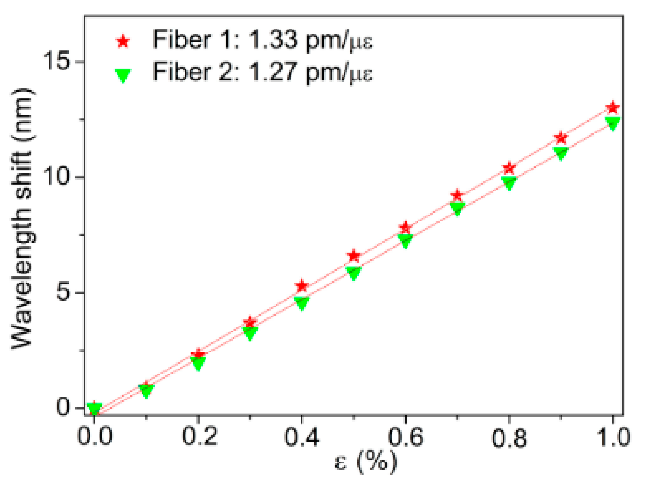
| mPOF | PMMA | 325 nm CW He-Cd laser | without annealing preform | - | - | 1.27 ± 0.01 pm/με | - | - | [39] |
| annealing preform | 80 °C | 2 week | 1.33 ± 0.01 pm/με | - | - | ||||
| mPOF | PMMA | 325 nm He-Cd laser | without post-annealing | - | - | 0.681 ± 0.009 pm/με | 0.141 ± 0.018 pm/kPa | 10.92 ± 1.37 pm/mN | [59] |
| post-annealed under water | 60 ± 2 °C | 2 min | 0.739 ± 0.019 pm/με | 0.217 ± 0.022 pm/kPa | 13.65 ± 1.37 pm/mN | ||||
| without post-annealing | - | - | 0.708 ± 0.007 pm/με | 0.180 ± 0.023 pm/kPa | 10.92 ± 1.37 pm/mN | ||||
| post-annealed under water | 60 ± 2 °C | 4 min | 0.902 ± 0.016 pm/με | 0.260 ± 0.025 pm/kPa | 14.33 ± 1.37 pm/mN | ||||
| without post-annealing | - | - | 0.771 ± 0.011 pm/με | 0.173 ± 0.024 pm/kPa | 13.41 ± 1.85 pm/mN | ||||
| post-annealed under water | 60 ± 2 °C | 30 min | 0.943 ± 0.011 pm/με | 0.202 ± 0.026 pm/kPa | 14.64 ± 1.85 pm/mN | ||||
| without post-annealing | - | - | 0.711 ± 0.007 pm/με | 0.163 ± 0.026 pm/kPa | 12.24 ± 1.96 pm/mN | ||||
| post-annealed under water | 55 ± 2 °C | 30 min | 0.879 ± 0.020 pm/με | 0.191 ± 0.018 pm/kPa | 14.37 ± 1.34 pm/mN | ||||
| GI MM POF | CYTOP | 517 nm fs laser system (HighQ laser femtoREGEN) | without post-annealing | - | - | 1.13 pm/με | - | −188.3 pm/N | [68] |
| post-annealed at low humidity | 90 °C | 24 h | 0.95 pm/με | - | −225.0 pm/N | ||||
| post-annealed under water | 90 °C | 24 h | 1.69 pm/με | - | −341.7 pm/N |
Disclaimer/Publisher’s Note: The statements, opinions and data contained in all publications are solely those of the individual author(s) and contributor(s) and not of MDPI and/or the editor(s). MDPI and/or the editor(s) disclaim responsibility for any injury to people or property resulting from any ideas, methods, instructions or products referred to in the content. |
© 2023 by the authors. Licensee MDPI, Basel, Switzerland. This article is an open access article distributed under the terms and conditions of the Creative Commons Attribution (CC BY) license (https://creativecommons.org/licenses/by/4.0/).
Share and Cite
Qu, H.; Huang, W.; Lin, Z.; Cheng, X.; Min, R.; Teng, C.; Caucheteur, C.; Hu, X. Influence of Annealing on Polymer Optical Fiber Bragg Grating Inscription, Stability and Sensing: A Review. Sensors 2023, 23, 7578. https://doi.org/10.3390/s23177578
Qu H, Huang W, Lin Z, Cheng X, Min R, Teng C, Caucheteur C, Hu X. Influence of Annealing on Polymer Optical Fiber Bragg Grating Inscription, Stability and Sensing: A Review. Sensors. 2023; 23(17):7578. https://doi.org/10.3390/s23177578
Chicago/Turabian StyleQu, Hang, Weiyuan Huang, Zhoupeng Lin, Xin Cheng, Rui Min, Chuanxin Teng, Christophe Caucheteur, and Xuehao Hu. 2023. "Influence of Annealing on Polymer Optical Fiber Bragg Grating Inscription, Stability and Sensing: A Review" Sensors 23, no. 17: 7578. https://doi.org/10.3390/s23177578