1. Introduction
Due to the limitations of the technical environment and technology, ambient light affects the quality of the photos taken by the camera. This leads to the problems of reduced image quality, reduced viewing distance, and reduced effective information contained in the images. Reduced illumination in the image leads to reduced model accuracy in target tracking and detection. Low-light image enhancement plays a very important role in image processing and machine vision. However, at present, most AL algorithms rely on pairs of training data to train the image-to-image mapping relationship. These data sets are difficult to obtain in real scenes. Therefore, the non-reference low light image enhancement algorithm has a high research value and is challenging.
Many deep learning methods have been proposed to deal with low light enhancement problems. LPNet [
1] introduced the Gaussian-Laplacian image pyramid decomposition technique, which enhanced the effectiveness of low-light image enhancement methods. In Retinex-Net [
2], the Retinex theory was used to decompose the image, which reduced the noise while enhancing the brightness of the image. CycleGAN [
3] utilizes the GAN (Generative Adversarial Network) approach for cycle-consistent supervision, which enhances the effectiveness of image mapping learning. However, these methods have a major drawback, which is the need for a significant amount of effort to collect or create a sufficient number of paired training data. Additionally, the quality of these training data greatly affects the performance of the algorithm. Moreover, the existing methods mostly rely on learning the mapping relationship between images, but this approach heavily depends on the training images and may not achieve satisfactory restoration results when there is a significant disparity between the image scene and the training images. To address this issue, the main focus of this research is unsupervised low-light image enhancement methods (also known as zero-shot low-light image enhancement methods), which aim to enhance the illumination of images without paired low-light image data.
In this paper, we propose a method based on deep learning, which can cope with various conditions of images, such as illumination conditions, including uneven illumination and poor brightness. Different from the method of learning image-to-image mapping, in order to avoid the model relying too much on paired images, we use the method of estimating the parameters of the enhancement curve to enhance it. We design a differentiable curve and use deep learning technology to learn the adjustable parameters of the curve.
Figure 1 is a small example of low-light enhancement. We have selected one of the current two mainstream methods and compared its results with the methods in this article. EnlightenGAN [
4] uses GAN (Generative Adversarial Networks)’s [
5] method for low-light image enhancement, which has more obvious advantages compared to end-to-end methods. At the same time, the supervised method has a larger model volume and stronger image supervision information compared to this method. From the above figure, it can be seen that the rendering of this method has better restoration and visual effects compared to the other two methods in terms of image quality. Due to the end-to-end training approach adopted in this method, compared to the other two methods, this method may have shortcomings in restoring some details of the image. This is because other methods have improved the restoration effect of local areas after adding corresponding modules. However, from the graph, it can be seen that the method proposed in this article can still produce good image restoration results. The reason for the brighter image effect of this method is that due to the lack of contrasting ground truth images, the overall brightness of the image will become brighter.
The contributions of this article are as follows:
For unsupervised low-light image enhancement tasks, this article proposes a solution that incorporates intermediate images to enhance the illumination of the image through a two-stage method.
We design a set of Loss functions for zero sample low light image enhancement and prove their effectiveness.
We design a parameter grouping enhancement method to enhance the robustness of the network model in low-light image enhancement tasks.
2. Related Work
2.1. Low Light Enhancement
In the past decades, scholars have proposed many low light image enhancement algorithms, which mainly go through three stages: histogram equalization, Retinex theory, and convolutional neural network.
Histogram equalization is the most classic image enhancement algorithm in the early days. This algorithm calculates the frequency of input image pixels so that the histogram of input image pixels conforms to the distribution, thus improving the image contrast. This type of method is easy to implement, but it ignores the excessive enhancement caused by local brightness differences in the image and generates strong noise.
The second stage is an algorithm based on Retinex theory, which believes that the color of an object is not affected by light and has color constancy. Therefore, the image is decomposed into two parts: the illumination component and the reflection component. Among them, the reflection component is the intrinsic property of an object that is independent of lighting conditions, and the lighting component can reflect the difference between low light and normal light. The algorithm based on this theory first estimates the illumination component of low-light images and then enhances them to obtain corresponding normal-light images. The single-scale Retinex algorithm [
6] is the first low-light image enhancement algorithm based on Retinex theory, which ensures the smoothness of the illumination image through a Gaussian filter. The next multi-scale Retinex algorithm with color restoration [
7] is improved on the basis of single-scale SSR, which uses a Gaussian filter of different scales and performs color restoration. In recent years, many low-light image enhancement algorithms combined with Retinex theory have been proposed. NPE [
8] uses logarithmic transformation and Retinex theory to jointly enhance image contrast and maintain the naturalness of image illumination; SRIE [
9] proposed a weighted variational model to estimate both reflection and illumination components simultaneously; LIME [
10], on the other hand, only estimates the illumination component and outputs the reflection component as the enhancement result; MF estimates illumination components based on closed operations in morphology, and fuses multiple images for low light image enhancement. Although the above algorithms have achieved good results in certain scenarios, they cannot overcome the natural drawbacks of the Retinex theory. Their performance is limited by the model’s ability to decompose reflection and illumination components, and sometimes manual parameter adjustments are required, resulting in weak pan-Chinese ability. Moreover, most of these methods overlook noise and color distortion.
The emergence of deep learning and convolutional neural networks has greatly promoted the development of image restoration technology. Retinex Net [
2] combines Retinex theory with deep learning. MBLLEN [
11] achieves low illumination image enhancement and maintains image quality through feature fusion. DeepUPE [
12] first estimates the brightness map of the image and designs a special brightness loss function to adjust brightness. EnlightenGAN [
4] and Zero DCE [
13] take a different approach in the case of not using paired data for training.
2.2. Vision Transformers
The application of Transformers [
14] in computer vision and low-level image processing has grown. Many Researchers’ innate attention mechanism, which gives them the ability to recognize long-term dependencies in the data, is the key to their success. Transformers have recently shown amazing performance in computer vision tasks, particularly in picture classification [
15,
16,
17], segmentation [
17,
18], and object detection [
19,
20]. Many researchers have begun employing transformers for these tasks.
To allow transformers to handle 2D images, an input image is divided into non-overlapping patches of size (P, P). Each patch is flattened and projected to a d-dimensional vector via a trainable linear projection, forming the patch embeddings where H, W are the height and width of the image, respectively, C is the number of channels, and is the total number of patches. Finally, N is the effective input sequence length for the transformer encoder. Patch embeddings are enhanced with position embeddings to retain 2D image positional information.
In [
14], the authors design a new vision transformer encoder by stacking blocks of multi-head self-attention (MSA) and MLP layers. To solve the problem of gradient explosion or gradient dispersion, a residual mechanism is applied after every block,
with dimension d as input; an MSA block produces an output sequence
via
where
,
and
are
learnable matrices. Then it transforms the sequence
to keys, queries, and values, respectively.
is a linear combination of all the values in
weighted by the attention matrix
. In turn,
is calculated from similarities between the keys and query vectors.
Transformers compute self-attention
and use that information
to build models. Self-attention cannot be applied directly to images as
since it quickly becomes uncontrollable due to its quadratic cost in time and space. Due to this intrinsic limitation, modality-aware sequence length constraints have been used to limit sequence length while preserving model performance. A transformer design can be applied directly to medium-sized image patches for various vision applications, as demonstrated in reference [
15]. This local self-attention reduces the aforementioned memory constraints.
In low-level vision areas, transformer-based models have also made much progress on several sub-directions, such as image super-resolution [
21], image restoration [
22,
23], image colorization [
24], and bad weather restoration [
25]. Very recently, MAXIM [
26] used an MLPbased model in low-level vision areas which also shows MLP’s potential on low-level vision tasks. However, existing transformer & MLP models require much computational cost (e.g., 115.63M for IPT [
27], 14.14M for MAXIM [
26]), making it hard to implement on mobile and edge devices. Similarly, its application in the field of low-light image enhancement often incurs significant model overhead, and the method model proposed in this article can effectively solve this problem.
3. Method
3.1. Motivation
In traditional image processing, it is known that the general process of image restoration is the mapping between the pixels of the input image
and the restored image
, which can be represented by the following formula:
Generally speaking, the features of an image are extracted first through a shallow feature extractor to initially extract the detailed information in the image, which is usually implemented by a single convolution layer with a convolution kernel size of 3. After extracting the preliminary shallow information of the image, the image detail information is extracted from the original image by stacking convolutional layers. In the method proposed in this paper, we introduce the Transformer structure to enhance the performance of feature extraction. It uses a finer-grained feature extraction process to better extract the features of the image, and at the same time, it can also perform better for many details of the image it deals with.
In previous experiments, we found that simply using stacked convolutional layers or Transformer layers can lead to the recovery of some useless image details in the image feature map during the recovery process. In this article, we used a gating mechanism to filter out useless information, which is different from other methods where we use the hardware function for processing, it can filter out some useless details in the extracted image features. In addition, to address the issue of convolutional layers not being able to effectively process images, we have also adopted a Transformer structure to enhance the feature extraction ability of the image. At the same time, we have also reduced the size of the multi-head attention module in the network module, reducing the size of the model and improving processing speed.
3.2. Model Structure
Figure 2 shows the pipeline of our architecture proposed in this article, which consists of two parts: (i) the image feature extraction stage and (ii) the iterative enhancement stage. This method first takes low-light images as input and uses the network output as parameters for each iteration of enhancement. By training the image feature extraction network, it can output the best results. At the same time, in order to improve the ability of image feature extraction, we introduced the Transformer structure and introduced a new loss function to ensure that the image recovered from the network will not have sudden changes in pixel brightness. We also introduced new HDFN modules and modules to improve the network performance.
3.3. Image Feature Extraction Net
The function of an image feature extraction network is to extract the detailed features of the image from the original image features through a neural network and convert them into enhancement parameters. The overall network adopts an encoder-decoder structure, in which the convolutional layers in the original architecture are replaced with the proposed MHTransformer module introduced in this paper. This replacement aims to enhance the network’s feature extraction capability for the original low-light images, ultimately generating higher-quality parameter matrices.
MHTransformer This article introduces the Transformer module to enhance the detailed feature extraction function of the model. As usual, the structure in this article also includes two parts: a multi-head attention stage and a forward propagation stage. In order to better preserve the detailed features of the image while removing useless information from the detailed features, this article designs an MDTA module and an HDFN module.
MDTA In the Transformer structure, the main computational burden comes from the self-attention mechanism layer. Due to this process, there are usually three steps required for processing.
Given a Query and a series of Key-Value pairs, map an output together. This includes three steps:
Measure the similarity between Query and Key
Scaling and standardizing the obtained similarity measure
Weighting weights with Value
In this process, it will bring huge computational overhead to the entire network, and when the self-attention mechanism is applied to high-resolution images, this problem becomes increasingly serious, seriously affecting its application in the field of image restoration. To address this issue, we introduced MDTA, which has linear complexity. The key to this structure’s linear complexity is that we applied the self-attention mechanism (SA) to the channel dimension rather than the spatial dimension. Therefore, we introduced MDTA with linear complexity here, and also introduced deep separable convolutions into the structure. After obtaining a layer normalization tensor, the module first propagates forward to generate query (Q), key (K), and value (V). By applying 1 × 1 convolution to aggregate pixel and cross channel contexts, and applying 3 × 3 deep convolution to encode channel level spatial contexts, the module generates
,
,
. Among
is
point by point convolution and
is
deep convolution. Overall, the module process is defined as
where
and
are input and output feature maps; A matrix
,
,
is obtained by modifying a tensor from its original size.The MDTA structure is shown in
Figure 3.
HDFN The ordinary forward propagation module operates on the values at each pixel position. It uses two convolutions, one to extend the feature channel and the second to reduce the channel back to the original input dimension. The HDFN structure is shown in the figure above. We hope to filter out the required information through a gating mechanism. In this architecture, the gating mechanism is formalized as the product of elements of two parallel paths in the linear transformation layer, and one of them is activated using Hardswish [
28]. At the same time, we also use deep separable convolution in the network to encode information from adjacent pixel positions in space, which is very useful in many image restoration tasks.
Given an input tensor
, HDFN is formalized as follows:
wherein,
represents the element by element multiplication,
represents the Hardswish activation function, and LN is the layer normalization. The HDFN structure is shown in
Figure 4.
3.4. Iterative Enhancement Net
After extracting image detail features from the original low-light image and converting them into an enhancement parameter matrix, it is necessary to use the parameter matrix to enhance the image pixel by pixel. In order to make the enhancement network in this paper better adapt to different image environments, a parameter matrix block enhancement method is designed in this paper, which can better cope with various lighting conditions in the image.
Enhancement function Inspired by traditional image processing methods that focus on pixel-to-pixel enhancement, this paper references their approach and designs an enhancement function for mapping pixels from the original low-light image to the pixels in the enhanced image with improved illumination. In order to make the image enhancement function effective, the function should have the following two characteristics: (1) The image is a high-order curve that can better simulate the mapping relationship between image pixels. (2) The image should be smooth and differentiable, which can ensure the quality and smoothness of lighting after image restoration. The function designed in this article is as follows:
In the function, represents the parameters estimated by the network and indicates multiple enhancement stages. In this study, the same enhancement curve is used in multiple stages but with different parameters. This is done to better adapt to various low-light scenes in the image during the network enhancement process in order to achieve the best enhancement effects.
Parameter matrix block enhancement method The existing multi-stage enhancement methods use the same module and parameters for enhancement. The disadvantage of this enhancement method is that for some images with uneven lighting, the same model and parameters can cause excessive enhancement of the image. To solve this problem, this article proposes a parameter matrix block enhancement method. The advantage of dividing the estimated parameter matrix into blocks and applying it to each enhancement is that during the training process of the neural network, the network can adapt to different circumstances. The comparison between the two methods is illustrated in
Figure 5:
As shown in
Figure 5, the parameter matrix is incorporated into the enhancement curve on a pixel-to-pixel basis, and the calculations are performed using the curve. In the figure, E(x) represents the
mentioned earlier in the text.
3.5. Loss Function
As an unsupervised method, this method needs to introduce an unsupervised loss function for network training due to the lack of supervision of paired images during training. Regarding the images of the restored illumination obtained in the two stages mentioned earlier, this paper calculates their respective loss function values. Subsequently, these values are employed to train and optimize the entire network model, resulting in the attainment of a well-optimized network model. The five loss function introduced in this method will be introduced below.
Spatial loss In the process of enhancing lighting, the pre-enhanced and post-enhanced images should have spatial consistency, and the loss of spatial consistency is mainly used to ensure the spatial consistency of the enhanced image, mainly by ensuring the difference in adjacent areas between the original image and the enhanced image.
where
is the number of local regions and is the four adjacent regions of region i (top, bottom, left, and right). We define Y and use it as the average intensity value of the local area of the enhanced image. For the size of the local area, first set it to
.
Exposure controller loss function In order to solve this problem, the exposure control loss function is introduced to suppress these areas. Specifically, the average intensity value under good exposure is first defined. Then for each local area, the difference between its average intensity value and the average intensity value under good exposure is calculated. For the average intensity value of good lighting, set it to 0.6. The exposure control loss can be expressed using the following formula.
In the formula, M represents the number of non-overlapping regions in the image (using small regions for non-overlapping segmentation), and Y is the average intensity value of local regions in the enhanced image.
Color consistency loss In order to make the color of the enhanced image visually acceptable, a color consistency loss function is designed to control the overall color of the image. From the formula, we can see that the pixel contrast formula is as follows:
The formula represents the average intensity value of the channels in the enhanced image, and represents the average intensity value of the channels.
Light smoothing loss In order to maintain the monotonic relationship between adjacent pixels, lighting smoothing loss is introduced, and the formula is as follows:
TV loss Generally speaking, there are many image quality issues in dark images, with the most significant being the impact of image noise. Therefore, in this chapter, total variational loss is introduced to suppress noise in the image.
Total loss The formula of the total Loss function is as follows.
wherein
,
,
,
and
is the weight parameter.
4. Experiments
In order to demonstrate the superiority of this method in unsupervised low-light image enhancement tasks, experiments were conducted, and the results were compared with current advanced low-light image enhancement algorithms. During the experiment, the algorithm was implemented using the Python framework, with a single RTX3090 graphics card as the GPU.
4.1. Experimental Setting
Datasets Typically, CNN-based methods require paired datasets for operation, while GAN-based methods require carefully selected non-paired training data. In this task, it is necessary to estimate the curve parameters from the input images. Therefore, when selecting training data, images with different exposure levels were selected to enhance the robustness of this method. This also proves that our proposed method has good adaptability to low-light images. So we chose to select images with different exposure levels from the first part of the SICE dataset [
29] and segment them as training and validation sets to train our proposed network. To validate the effectiveness of the proposed method in this paper, a series of experiments were conducted using five publicly available benchmark datasets DICM [
30], LIME [
10], VV [
31], MEF [
32], and Fusion [
15] specifically designed for low-light image enhancement. These datasets exclusively consist of low-light images without their corresponding normal-light counterparts. The reason behind selecting these datasets is that comparing only the restoration quality metrics would be insufficient for evaluating the performance of low-light image enhancement. Therefore, in this study, a combination of metric comparisons and visual effect demonstrations was employed to comprehensively evaluate the experimental results and demonstrate the efficacy of the proposed method.
Hyperparameters The training batch size used in the experiment is 2, the validation batch size is 4, the initial learning rate is 0.0001, and the weight attenuation is 0.0001.
Training and inference strategies In this experiment, the non-reference loss function is directly used to train the network. In order to compare the effect of this method and other comparison methods, reasoning is carried out at the same resolution.
4.2. Experimental Evaluation Indicators
Due to the lack of corresponding images of normal lighting in the test set used in the experiment, the NIQE [
33], PIQE [
34], and BRISQUE [
35] evaluation index is used for comparison of experimental results.
In addition, in low-light image enhancement tasks, the superiority of visual effects is more important than metric performance. The reason this paper uses these three metrics instead of PSNR [
36] or SSIM [
37] is that these three metrics can better evaluate the visual effects of images, avoiding the situation where the low-light enhancement results are affected by the poor quality of the reference image.
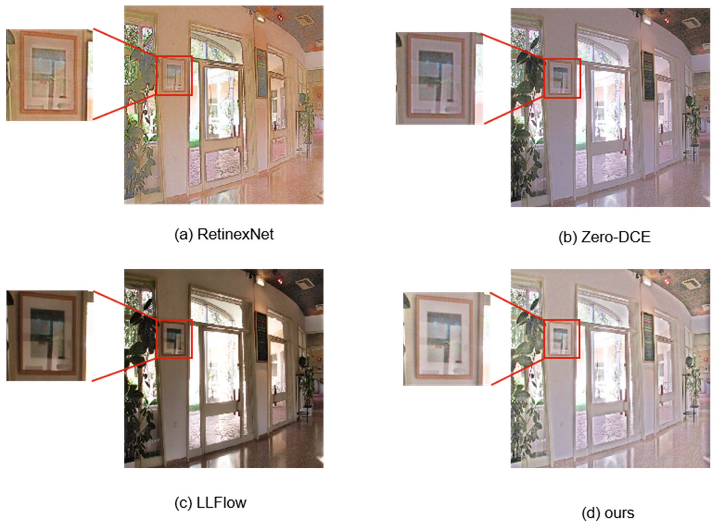
4.3. Comparison with Other Methods
In order to demonstrate the effectiveness of this method compared to other methods, this article compared it with other methods on several datasets. Due to the lack of corresponding normal lighting data in the selected test dataset, all tests in this article used single image evaluation indicators for performance comparison. For the selection of other methods for comparison, as the research object in this article is unsupervised methods, which have disadvantages compared to supervised methods, several representative supervised/unsupervised methods have been selected here. The comparison of visualization results and indicator results is shown in
Figure 6 and
Table 1. In addition, a comparative analysis of the method’s performance in terms of details was also conducted, as shown in
Figure 7.
4.4. Speed Test
As mentioned earlier, one advantage of the proposed method in this article is the small size of the model and fast inference speed. Many personal applications have migrated from traditional desktop platforms to mobile platforms. Therefore, it is necessary to explore the application of deep learning on mobile devices and embedded platforms. In order to verify the advantages of this article, this article used the method proposed in this article to test on the same test set on the desktop; the desktop device is equipped with an AMD Ryzen 5600X CPU, 24GB of RAM, and an NVIDIA RTX 3060 GPU, then we calculated the inference speed. The image resolution used for inference is 512 × 512 pixels in all cases. The test results are given in
Table 2.
From the above table, it can be seen that this experiment can still approach real-time (24FPS) after introducing a Transformer based structure with good inference performance and application prospects.
In addition to conducting inference speed testing on the PC end, speed testing was also conducted on the mobile end. Unlike the PC end, due to the limitations of the mobile code library, images cannot be uniformly sized and cropped. Therefore, experiments were only conducted on the original resolution of each dataset, but this did not affect the analysis of the experimental results. The mobile platform used for inference is Honor 30S; it is equipped with a Kirin 820 (up to 2.36 GHz) processor and 8 GB of RAM. The image resolution used for inference is 640 × 640 pixels in all cases. The test results are given in
Table 3.
From the experimental results, it can be observed that the proposed method in this paper achieves an inference time of under 1 s on mobile devices, making it highly promising for applications on devices with limited memory and computational resources.
In addition, it is worth mentioning that the model proposed in this paper has a size of only 99 M, even after incorporating Transformer structures. This presents an unparalleled advantage compared to other methods, such as HWMNet, which has a size close to 700 M. Given the limited storage capacity of mobile devices, this advantage is remarkable. Future research will also consider further exploring the applicability of the proposed model.
4.5. Ablation Experiment
In this section, regarding the key component designed in this paper as mentioned, in order to demonstrate the improvement in low-light image illumination restoration, an ablation experiment is conducted specifically on the proposed improvement part in this paper, affirming its effectiveness.
Influence of Loss function on indicators and visual effects In order to verify the effect of several loss functions introduced by the method in this paper, the following are the visual effects and data indicators of the effect of the loss function. The comparison results are shown in
Figure 8 and
Table 4.
Ablation result of enhancement method As mentioned earlier, a new parameter enhancement method was proposed in this article. In order to further validate the effectiveness of the method, ablation experiments were conducted under the same experimental conditions, and the experimental indicators (NIQE) results are shown in
Table 5.
From the above table, it can be seen that the parameter-blocking enhancement method proposed in this article has significantly improved the lighting restoration effect of images.
The Impact of Gating Mechanism Selection In the past deep learning practice, there were generally three choices of Activation function: Relu, Gelu, and Hardswish, which can be seen from the image is the selection of the hardswish Activation function is more effective for filtering useless information. In order to show the effect of the selected Activation function more clearly, ablation experiments on recovery indicators were also conducted for the selection of the Activation function. The experimental indicators (NIQE) results are shown in
Table 6.
From the above table, we can see that the gating mechanism of the hardswish Activation function used in this paper can effectively filter out the useless information in the image features and improve the image illumination enhancement effect.
4.6. Superiority and Limitation
In the previous discussion, this paper analyzed the key structures in the method and presented the experimental results. It can be seen that the proposed method in this paper has several advantages compared to previous methods:
Compared to previous methods, this paper has a significant advantage in terms of model size. It can be effectively deployed on edge devices
An effective zero-shot low-light enhancement approach is proposed in this paper, which can effectively enhance low-light images without the need for paired training datasets
However, the method proposed in this paper still has the following two limitations:
Due to the limitations of the zero reference method, this paper is still not very effective in preserving some of the detailed features of the image.
As this paper uses estimated enhancement parameters for light enhancement of the image, the overall brightness of the image will be on the light side.
5. Conclusions
To address the problems of excessive model inference speed in low-light image enhancement tasks and the inability to obtain paired training datasets in real-world scenarios, an unsupervised low-light image enhancement method is proposed in this paper. A two-stage low light image enhancement network is also proposed to address the shortcomings of previous single-stage networks by proposing the concept of intermediate graphs to extract detailed features from input images. The test results on the test set indicate that the proposed method has better recovery performance compared to other existing unsupervised methods. The good applicability of the proposed method has also been verified by experiments in this paper.
6. Future Works
For the zero-shot low-light image enhancement method studied in this paper, the core issue is how to evaluate image quality and calculate the loss function to optimize the network in the absence of reference images. We have noticed that besides the intrinsic features of the image itself, there is other useful information, such as semantic information and classification information, that can be utilized. In future research, these pieces of information can be employed to supervise the network and further improve the authenticity of image restoration.
Author Contributions
Conceptualization, J.T.; Methodology, J.T. and J.Z.; Writing—original draft, J.T.; Writing—review & editing, J.Z.; Supervision, J.Z. All authors have read and agreed to the published version of the manuscript.
Funding
This research was funded by Key R&D Projects in Sichuan Province (Research on Intelligent Sensing Methods for Multimodal Targets in Complex Driving Environments)(2022YFG0261).
Institutional Review Board Statement
Not applicable.
Informed Consent Statement
Not applicable.
Data Availability Statement
The data that support the findings of this study are available from the corresponding author upon reasonable request.
Conflicts of Interest
The authors declare no conflict of interest.
References
- Fu, X.; Liang, B.; Huang, Y.; Ding, X.; Paisley, J. Lightweight pyramid networks for image deraining. IEEE Trans. Neural Netw. Learn. Syst. 2019, 31, 1794–1807. [Google Scholar] [CrossRef] [PubMed]
- Wei, C.; Wang, W.; Yang, W.; Liu, J. Deep retinex decomposition for low-light enhancement. arXiv 2018, arXiv:1808.04560. [Google Scholar] [CrossRef]
- Zhu, J.-Y.; Park, T.; Isola, P.; Efros, A.A. Unpaired image-to-image translation using cycle-consistent adversarial networks. In Proceedings of the IEEE International Conference on Computer Vision, Venice, Italy, 22–29 October 2017. [Google Scholar]
- Jiang, Y.; Gong, X.; Liu, D.; Cheng, Y.; Fang, C.; Shen, X.; Yang, J.; Zhou, P.; Wang, Z. Enlightengan: Deep light enhancement without paired supervision. IEEE Trans. Image Process. 2021, 30, 2340–2349. [Google Scholar] [CrossRef] [PubMed]
- Goodfellow, I.; Pouget-Abadie, J.; Mirza, M.; Xu, B.; Warde-Farley, D.; Ozair, S.; Courville, A.; Bengio, Y. Generative adversarial networks. Commun. ACM 2020, 63, 139–144. [Google Scholar] [CrossRef]
- Jobson, D.J.; Rahman, Z.; Woodell, G.A. Properties and performance of a center/surround retinex. IEEE Trans. Image Process. 1997, 6, 451–462. [Google Scholar] [CrossRef] [PubMed]
- Jobson, D.J.; Rahman, Z.; Woodell, G.A. A multiscale retinex for bridging the gap between color images and the human observation of scenes. IEEE Trans. Image Process. 1997, 6, 965–976. [Google Scholar] [CrossRef] [PubMed]
- Wang, S.; Zheng, J.; Hu, H.M.; Li, B. Naturalness preserved enhancement algorithm for non-uniform illumination images. IEEE Trans. Image Process. 2013, 22, 3538–3548. [Google Scholar] [CrossRef] [PubMed]
- Fu, X.; Liao, Y.; Zeng, D.; Huang, Y.; Zhang, X.P.; Ding, X. A probabilistic method for image enhancement with simultaneous illumination and reflectance estimation. IEEE Trans. Image Process. 2015, 24, 4965–4977. [Google Scholar] [CrossRef] [PubMed]
- Guo, X.; Li, Y.; Ling, H. LIME: Low-light image enhancement via illumination map estimation. IEEE Trans. Image Process. 2016, 26, 982–993. [Google Scholar] [CrossRef] [PubMed]
- Lv, F.; Lu, F.; Wu, J.; Lim, C. MBLLEN: Low-light image/video enhancement using CNNs. In Proceedings of the BMVC, Newcastle, UK, 3–6 September 2018; Volume 220, p. 4. [Google Scholar]
- Wang, R.; Zhang, Q.; Fu, C.W.; Shen, X.; Zheng, W.S.; Jia, J. Underexposed photo enhancement using deep illumination estimation. In Proceedings of the IEEE/CVF Conference on Computer Vision and Pattern Recognition, Long Beach, CA, USA, 15–20 June 2019; IEEE: Piscataway, NJ, USA, 2019; pp. 6849–6857. [Google Scholar]
- Guo, C.; Li, C.; Guo, J.; Loy, C.C.; Hou, J.; Kwong, S.; Cong, R. Zero-reference deep curve estimation for low-light image enhancement. In Proceedings of the IEEE/CVF Conference on Computer Vision and Pattern Recognition, Seattle, WA, USA, 13–19 June 2020; pp. 1780–1789. [Google Scholar]
- Vaswani, A.; Shazeer, N.; Parmar, N.; Uszkoreit, J.; Jones, L.; Gomez, A.N.; Kaiser, Ł.; Polosukhin, I. Attention is all you need. Adv. Neural Inf. Process. Syst. 2017, 30, 5998–6008. [Google Scholar]
- Dosovitskiy, A.; Beyer, L.; Kolesnikov, A.; Weissenborn, D.; Zhai, X. An image is worth 16x16 words: Transformers for image recognition at scale. arXiv 2020, arXiv:2010.11929. [Google Scholar]
- Wang, W.; Xie, E.; Li, X.; Fan, D.-P.; Song, K.; Liang, D.; Lu, T.; Luo, P.; Shao, L. Pyramid vision transformer: A versatile backbone for dense prediction without convolutions. In Proceedings of the IEEE/CVF International Conference on Computer Vision, Montreal, QC, Canada, 10–17 October 2021; pp. 568–578. [Google Scholar]
- Liu, Z.; Lin, Y.; Cao, Y.; Hu, H.; Wei, Y.; Zhang, Z.; Lin, S.; Guo, B. Swin transformer: Hierarchical vision transformer using shifted windows. In Proceedings of the IEEE/CVF International Conference on Computer Vision, Montreal, QC, Canada, 10–17 October 2021; pp. 10012–10022. [Google Scholar]
- Zheng, S.; Lu, J.; Zhao, H.; Zhu, X.; Luo, Z.; Wang, Y.; Fu, Y.; Feng, J.; Xiang, T.; Torr, P.H.; et al. Rethinking semantic segmentation from a sequence-to-sequence perspective with transformers. In Proceedings of the IEEE/CVF Conference on Computer Vision and Pattern Recognition, Nashville, TN, USA, 20–25 June 2021; pp. 6881–6890. [Google Scholar]
- Zhu, X.; Su, W.; Lu, L.; Li, B.; Wang, X.; Dai, J. Deformable detr: Deformable transformers for end-to-end object detection. arXiv 2020, arXiv:2010.04159. [Google Scholar]
- Carion, N.; Massa, F.; Synnaeve, G.; Usunier, N.; Kirillov, A.; Zagoruyko, S. End-to-end object detection with transformers. In Proceedings of the Computer Vision–ECCV 2020: 16th European Conference, Glasgow, UK, 23–28 August 2020; Proceedings, Part I 16. Springer International Publishing: New York, NY, USA, 2020; pp. 213–229. [Google Scholar]
- Yang, F.; Yang, H.; Fu, J.; Lu, H.; Guo, B. Learning texture transformer network for image super-resolution. In Proceedings of the IEEE/CVF Conference on Computer Vision and Pattern Recognition, Seattle, WA, USA, 13–19 June 2020; pp. 5791–5800. [Google Scholar]
- Wang, Z.; Cun, X.; Bao, J.; Zhou, W.; Liu, J.; Li, H. Uformer: A general u-shaped transformer for image restoration. In Proceedings of the IEEE/CVF Conference on Computer Vision and Pattern Recognition, New Orleans, LA, USA, 18–24 June 2022; pp. 17683–17693. [Google Scholar]
- Liang, J.; Cao, J.; Sun, G.; Zhang, K.; Van Gool, L.; Timofte, R. Swinir: Image restoration using swin transformer. In Proceedings of the IEEE/CVF International Conference on Computer Vision, Montreal, BC, Canada, 11–17 October 2021; pp. 1833–1844. [Google Scholar]
- Kumar, M.; Weissenborn, D.; Kalchbrenner, N. Colorization transformer. arXiv 2021, arXiv:2102.04432. [Google Scholar]
- Valanarasu, J.M.J.; Yasarla, R.; Patel, V.M. Transweather: Transformer-based restoration of images degraded by adverse weather conditions. In Proceedings of the IEEE/CVF Conference on Computer Vision and Pattern Recognition, New Orleans, LA, USA, 18–24 June 2022; pp. 2353–2363. [Google Scholar]
- Tu, Z.; Talebi, H.; Zhang, H.; Yang, F.; Milanfar, P.; Bovik, A.; Li, Y. Maxim: Multi-axis mlp for image processing. In Proceedings of the IEEE/CVF Conference on Computer Vision and Pattern Recognition, New Orleans, LA, USA, 18–24 June 2022; pp. 5769–5780. [Google Scholar]
- Chen, H.; Wang, Y.; Guo, T.; Xu, C.; Deng, Y.; Liu, Z.; Ma, S.; Xu, C.; Xu, C.; Gao, W. Pre-trained image processing transformer. In Proceedings of the IEEE/CVF Conference on Computer Vision and Pattern Recognition, Nashville, TN, USA, 20–25 June 2021; pp. 12299–12310. [Google Scholar]
- Howard, A.; Sandler, M.; Chu, G.; Chen, L.C.; Chen, B.; Tan, M.; Wang, W.; Zhu, Y.; Pang, R.; Vasudevan, V.; et al. Searching for mobilenetv3. In Proceedings of the IEEE/CVF International Conference on Computer Vision, Seoul, Republic of Korea, 27 October–2 November 2019; pp. 1314–1324. [Google Scholar]
- Cai, J.; Gu, S.; Zhang, L. Learning a deep single image contrast enhancer from multi-exposure images. IEEE Trans. Image Process. 2018, 27, 2049–2062. [Google Scholar] [CrossRef] [PubMed]
- Lee, C.; Lee, C.; Kim, C.-S. Contrast enhancement based on layered difference representation. In Proceedings of the 2012 19th IEEE International Conference on Image Processing, Orlando, FL, USA, 30 September–3 October 2012; p. 6. [Google Scholar]
- Vonikakis, V.; Chrysostomou, D.; Kouskouridas, R.; Gasteratos, A. Improving the robustness in feature detection by local contrast enhancement. In Proceedings of the 2012 IEEE International Conference on Imaging Systems and Techniques Proceedings, Manchester, UK, 16–17 July 2012; IEEE: Piscataway, NJ, USA, 2012; pp. 158–163. [Google Scholar]
- Ma, K.; Zeng, K.; Wang, Z. Perceptual quality assessment for multi-exposure image fusion. IEEE Trans. Image Process. 2015, 24, 3345–3356. [Google Scholar] [CrossRef] [PubMed]
- Mittal, A.; Soundararajan, R.; Bovik, A.C. Making a “completely blind” image quality analyzer. IEEE Signal Process. Lett. 2012, 20, 209–212. [Google Scholar] [CrossRef]
- Venkatanath, N.; Praneeth, D.; Bh, M.C.; Channappayya, S.S.; Medasani, S.S. Blind image quality evaluation using perception based features. In Proceedings of the 2015 Twenty First National Conference on Communications (NCC), Mumbai, India, 27 February–1 March 2015; IEEE: Piscataway, NJ, USA, 2015; pp. 1–6. [Google Scholar]
- Mittal, A.; Moorthy, A.K.; Bovik, A.C. No-reference image quality assessment in the spatial domain. IEEE Trans. Image Process. 2012, 21, 4695–4708. [Google Scholar] [CrossRef]
- Hore, A.; Ziou, D. Image quality metrics: PSNR vs. SSIM. In Proceedings of the 2010 20th International Conference on Pattern Recognition, Istanbul, Turkey, 23–26 August 2010. [Google Scholar]
- Wang, Z.; Bovik, A.C.; Sheikh, H.R.; Simoncelli, E.P. Image quality assessment: From error visibility to structural similarity. IEEE Trans. Image Process. 2004, 13, 600–612. [Google Scholar] [CrossRef]
- Fan, C.M.; Liu, T.J.; Liu, K.H. Half Wavelet Attention on M-Net+ for Low-Light Image Enhancement. arXiv 2022, arXiv:2203.01296. [Google Scholar]
- Wang, Y.; Wan, R.; Yang, W.; Li, H.; Chau, L.-P.; Kot, A. Low-Light Image Enhancement with Normalizing Flow. arXiv 2021, arXiv:2109.05923. [Google Scholar] [CrossRef]
| Disclaimer/Publisher’s Note: The statements, opinions and data contained in all publications are solely those of the individual author(s) and contributor(s) and not of MDPI and/or the editor(s). MDPI and/or the editor(s) disclaim responsibility for any injury to people or property resulting from any ideas, methods, instructions or products referred to in the content. |
© 2023 by the authors. Licensee MDPI, Basel, Switzerland. This article is an open access article distributed under the terms and conditions of the Creative Commons Attribution (CC BY) license (https://creativecommons.org/licenses/by/4.0/).


