
Capture-Aware Dense Tag Identification Using RFID Systems in Vehicular Networks

Abstract
:1. Introduction
- A fading channel-capture model is established to analyze the capture probability in different channel environments, and the closed expression of the Nakagami-m fading channel capture probability is derived.
- We propose an advanced capture-aware estimation algorithm that quickly adjusts the initial frame length through the first few timeslots in a frame, reduces the delay caused by the lack of prior knowledge of the number of tags, and improves the estimation performance of both tags and capture probabilities.
- Considering the capture effect in fading channels and the duration of the slots, this paper dynamically adjusts the size of the next frame by combining the estimate of the number of tags and the capture probability, thus greatly improving the tag-identification rate. Compared with other excellent algorithms, the estimation method proposed in this paper shows better identification performance.
2. Background
2.1. Brief Analysis of ALOHA-Based Anti-Collision Algorithm
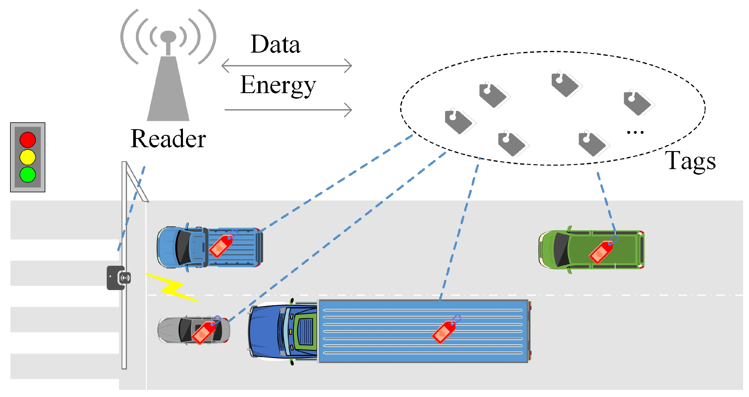
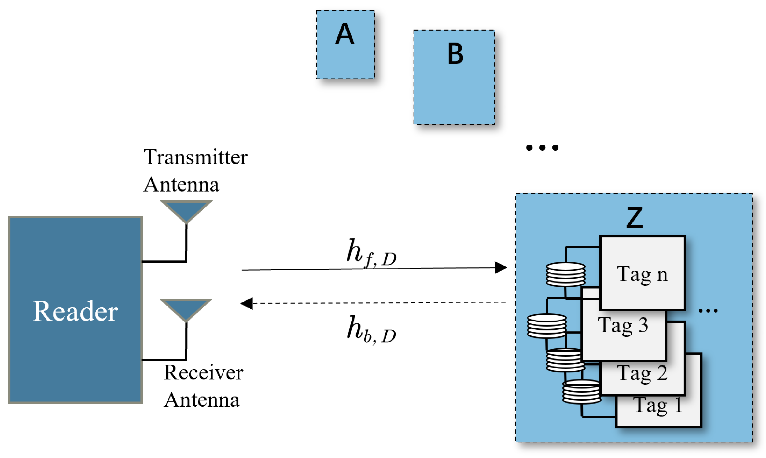
2.2. The Entire System under the Capture Effect
3. Capture Model of High-Density Tag Distribution
4. Capture-Aware Algorithm for Large-Scale Tag Identification
4.1. Proposed Estimation Algorithm
| Algorithm 1: Pseudo-code operation of a reader. |
 |
4.2. Frame Length Adjustment
4.3. Description of the Algorithm
5. Numerical and Analytical Result
6. Conclusions
Author Contributions
Funding
Institutional Review Board Statement
Informed Consent Statement
Data Availability Statement
Conflicts of Interest
References
- Wu, Q.; Nie, S.; Fan, P.; Liu, H.; Qiang, F.; Li, Z. A swarming approach to optimize the one-hop delay in smart driving inter-platoon communications. Sensors 2018, 18, 3307. [Google Scholar] [CrossRef] [PubMed] [Green Version]
- Wu, Q.; Zheng, J. Performance modeling and analysis of the ADHOC MAC protocol for VANETs. In Proceedings of the 2015 IEEE International Conference on c Communications (ICC), London, UK, 8–12 June 2015; pp. 3646–3652. [Google Scholar]
- Wu, Q.; Zhao, Y.; Fan, Q.; Fan, P.; Wang, J.; Zhang, C. Mobility-aware cooperative caching in vehicular edge computing based on asynchronous federated and deep reinforcement learning. IEEE J. Sel. Top. Signal Process. 2022, 17, 66–81. [Google Scholar] [CrossRef]
- Wu, Q.; Shi, S.; Wan, Z.; Fan, Q.; Fan, P.; Zhang, C. Towards V2I age-aware fairness access: A dqn based intelligent vehicular node training and test method. arXiv 2022, arXiv:2208.01283. [Google Scholar]
- Fan, J.; Yin, S.; Wu, Q.; Gao, F. Study on refined deployment of wireless mesh sensor network. In Proceedings of the 2010 6th International Conference on Wireless Communications Networking and Mobile Computing (WiCOM), Chengdu, China, 23–25 September 2010; pp. 1–5. [Google Scholar]
- Wu, Q.; Zheng, J. Performance modeling and analysis of the ADHOC MAC protocol for vehicular networks. Wirel. Netw. 2016, 22, 799–812. [Google Scholar] [CrossRef]
- Wu, Q.; Xia, S.; Fan, P.; Fan, Q.; Li, Z. Velocity-adaptive V2I fair-access scheme based on IEEE 802.11 DCF for platooning vehicles. Sensors 2018, 18, 4198. [Google Scholar] [CrossRef] [Green Version]
- Olaby, O.; Hamadache, M.; Soper, D.; Winship, P.; Dixon, R. Development of a novel railway positioning system using RFID technology. Sensors 2022, 22, 2401. [Google Scholar] [CrossRef]
- Shariq, M.; Singh, K.; Maurya, P.K.; Ahmadian, A.; Taniar, D. AnonSURP: An anonymous and secure ultralightweight RFID protocol for deployment in internet of vehicles systems. J. Supercomput. 2022, 78, 8577–8602. [Google Scholar] [CrossRef]
- Park, S.; Lee, H. Self-recognition of vehicle position using UHF passive RFID tags. IEEE Trans. Ind. Electron. 2012, 60, 226–234. [Google Scholar] [CrossRef]
- Qin, H.; Chen, W.; Chen, W.; Li, N.; Zeng, M.; Peng, Y. A collision-aware mobile tag reading algorithm for RFID-based vehicle localization. Comput. Netw. 2021, 199, 108422. [Google Scholar] [CrossRef]
- Wang, H.; Wang, S.; Yao, J.; Pan, R.; Huang, Q.; Zhang, H.; Yang, J. Effective anti-collision algorithms for RFID robots system. Assem. Autom. 2019, 40, 55–64. [Google Scholar] [CrossRef]
- Wu, G.; Xu, Z.; Zhang, H.; Shen, S.; Yu, S. Multi-agent DRL for joint completion delay and energy consumption with queuing theory in MEC-based IIoT. J. Parallel Distrib. Comput. 2023, 176, 80–94. [Google Scholar] [CrossRef]
- Zhang, P.; Chen, N.; Shen, S.; Yu, S.; Kumar, N.; Hsu, C.H. AI-Enabled Space-Air-Ground Integrated Networks: Management and Optimization. IEEE Netw. 2023. [Google Scholar] [CrossRef]
- Shen, S.; Wu, X.; Sun, P.; Zhou, H.; Wu, Z.; Yu, S. Optimal privacy preservation strategies with signaling Q-learning for edge-computing-based IoT resource grant systems. Expert Syst. Appl. 2023, 225, 120192. [Google Scholar] [CrossRef]
- Wang, C.; Jiang, C.; Wang, J.; Shen, S.; Guo, S.; Zhang, P. Blockchain-Aided Network Resource Orchestration in Intelligent Internet of Things. IEEE Internet Things J. 2022, 10, 6151–6163. [Google Scholar] [CrossRef]
- Li, G.; Sun, H.; Li, Z.; Wu, P.; Inserra, D.; Su, J.; Fang, X.; Wen, G. A Dynamic Multi-ary Query Tree Protocol for Passive RFID Anti-collision. CMC Comput. Mater. Contin. 2022, 72, 4931–4944. [Google Scholar] [CrossRef]
- Zhang, H.; Gao, L.; Luo, H.g.; Zhai, Y. Research on the RFID anticollision strategy based on decision tree. Wirel. Commun. Mob. Comput. 2022, 2022, 2913157. [Google Scholar] [CrossRef]
- Yang, X.; Wu, B.; Wu, S.; Liu, X.; Zhao, W.W. Time Slot Detection-Based M-ary Tree Anticollision Identification Protocol for RFID Tags in the Internet of Things. Wirel. Commun. Mob. Comput. 2021, 2021, 6638936. [Google Scholar] [CrossRef]
- Zhang, G.; Tao, S.; Cai, Q.; Gao, W.; Jia, J.; Wen, J. A fast and universal RFID tag anti-collision algorithm for the Internet of Things. IEEE Access 2019, 7, 92365–92377. [Google Scholar] [CrossRef]
- Zhong, D. An ALOHA-Based Algorithm Based on Grouping of Tag Prefixes for Industrial Internet of Things. Secur. Commun. Netw. 2022, 2022, 1812670. [Google Scholar] [CrossRef]
- Nafar, F.; Shamsi, H. Design and implementation of an RFID-GSM-based vehicle identification system on highways. IEEE Sens. J. 2018, 18, 7281–7293. [Google Scholar] [CrossRef]
- Qu, Z.; Sun, X.; Chen, X.; Yuan, S. A novel RFID multi-tag anti-collision protocol for dynamic vehicle identification. PLoS ONE 2019, 14, e0219344. [Google Scholar] [CrossRef]
- Global, E. EPC radio-frequency identity protocols class-1 generation-2 UHF RFID protocol for communications at 860 MHz–960 MHz. Version 2008, 1, 23. [Google Scholar]
- Menon, V.G.; Jacob, S.; Joseph, S.; Sehdev, P.; Khosravi, M.R.; Al-Turjman, F. An IoT-enabled intelligent automobile system for smart cities. Internet Things 2022, 18, 100213. [Google Scholar] [CrossRef]
- Salah, H.; Ahmed, H.A.; Robert, J.; Heuberger, A. A time and capture probability aware closed form frame slotted ALOHA frame length optimization. IEEE Commun. Lett. 2015, 19, 2009–2012. [Google Scholar] [CrossRef]
- Shin, W.J.; Kim, J.G. A capture-aware access control method for enhanced RFID anti-collision performance. IEEE Commun. Lett. 2009, 13, 354–356. [Google Scholar] [CrossRef]
- Li, B.; Wang, J. Efficient anti-collision algorithm utilizing the capture effect for ISO 18000-6C RFID protocol. IEEE Commun. Lett. 2011, 15, 352–354. [Google Scholar] [CrossRef]
- Yang, X.; Wu, H.; Zeng, Y.; Gao, F. Capture-aware estimation for the number of RFID tags with lower complexity. IEEE Commun. Lett. 2013, 17, 1873–1876. [Google Scholar] [CrossRef]
- Wang, Y.; Wu, H.; Zeng, Y. Capture-aware estimation for large-scale RFID tags identification. IEEE Signal Process. Lett. 2015, 22, 1274–1277. [Google Scholar] [CrossRef]
- Wu, H.; Wang, Y.; Zeng, Y. Capture-aware Bayesian RFID tag estimate for large-scale identification. IEEE/CAA J. Autom. Sin. 2017, 5, 119–127. [Google Scholar] [CrossRef]
- Chen, Y.; Feng, Q.; Senior Member, I.; Jia, X.; Chen, H. Modeling and analyzing RFID generation-2 under unreliable channels. J. Netw. Comput. Appl. 2021, 178, 102937. [Google Scholar] [CrossRef]
- Wang, H.; Yu, R.; Pan, R.; Liu, M.; Huang, Q.; Yang, J. Fast tag identification for mobile RFID robots in manufacturing environments. Assem. Autom. 2021, 41, 292–301. [Google Scholar] [CrossRef]
- Su, J.; Sheng, Z.; Liu, A.X.; Han, Y.; Chen, Y. Capture-aware identification of mobile RFID tags with unreliable channels. IEEE Trans. Mob. Comput. 2020, 21, 1182–1195. [Google Scholar] [CrossRef]
- Katagi, T.; Ohmine, H.; Miyashita, H.; Nishimoto, K. Analysis of mutual coupling between dipole antennas using simultaneous integral equations with exact kernels and finite gap feeds. IEEE Trans. Antennas Propag. 2016, 64, 1979–1984. [Google Scholar] [CrossRef]
- Sarkar, B.; Takeyeva, D.; Guchhait, R.; Sarkar, M. Optimized radio-frequency identification system for different warehouse shapes. Knowl.-Based Syst. 2022, 258, 109811. [Google Scholar] [CrossRef]
- Chen, W.; Childs, J.; Ray, S.; Lee, B.S.; Xia, T. RFID Technology Study for Traffic Signage Inventory Management Application. IEEE Trans. Intell. Transp. Syst. 2022, 23, 17809–17818. [Google Scholar] [CrossRef]
- Schoute, F. Dynamic frame length ALOHA. IEEE Trans. Commun. 1983, 31, 565–568. [Google Scholar] [CrossRef]
- Mokhtari, A.; Atani, R.E.; Maghsoodi, M. Using capture effect in DFSA anti-collision protocol in RFID systems according to ISO18000-6C standard. Majlesi J. Mechatron. Syst. 2012, 1, 26. [Google Scholar]
- Wang, J.; Shi, Y.; Yang, C.; Ji, S.; Su, H. Research on fading characteristics of ultrahigh frequency signals in Karst landform around radio quiet zone of FAST. Radio Sci. 2020, 55, 1–10. [Google Scholar] [CrossRef]
- Wang, Y.; Shi, J.; Chen, L.; Lu, B.; Yang, Q. A novel capture-aware TDMA-based MAC protocol for safety messages broadcast in vehicular ad hoc networks. IEEE Access 2019, 7, 116542–116554. [Google Scholar] [CrossRef]
- Sabesan, S.; Crisp, M.J.; Penty, R.V.; White, I.H. Wide area passive UHF RFID system using antenna diversity combined with phase and frequency hopping. IEEE Trans. Antennas Propag. 2013, 62, 878–888. [Google Scholar] [CrossRef]
- Gao, Y.; Chen, Y.; Bekkali, A. Performance of passive UHF RFID in cascaded correlated generalized Rician fading. IEEE Commun. Lett. 2016, 20, 660–663. [Google Scholar] [CrossRef] [Green Version]
- Zhang, Y.; Gao, F.; Fan, L.; Lei, X.; Karagiannidis, G.K. Secure communications for multi-tag backscatter systems. IEEE Wirel. Commun. Lett. 2019, 8, 1146–1149. [Google Scholar] [CrossRef]
- Jameel, F.; Haider, M.A.A.; Butt, A.A. Performance analysis of VANETs under Rayleigh, Rician, Nakagami-m and Weibull fading. In Proceedings of the 2017 International Conference on Communication, Computing and Digital Systems (C-CODE), Islamabad, Pakistan, 8–9 March 2017; pp. 127–132. [Google Scholar]
- Zhang, Y.; Gao, F.; Fan, L.; Lei, X.; Karagiannidis, G.K. Backscatter communications over correlated Nakagami-m fading channels. IEEE Trans. Commun. 2018, 67, 1693–1704. [Google Scholar] [CrossRef]
- Wang, Y.; Shi, J.; Chen, L. Capture Effect in the FSA-Based Networks under Rayleigh, Rician and Nakagami-m Fading Channels. Appl. Sci. 2018, 8, 414. [Google Scholar] [CrossRef]
- Khandelwal, G.; Lee, K.; Yener, A.; Serbetli, S. ASAP: A MAC protocol for dense and time-constrained RFID systems. EURASIP J. Wirel. Commun. Netw. 2007, 2007, 18730. [Google Scholar] [CrossRef] [Green Version]
- Vogt, H. Efficient object identification with passive RFID tags. In Pervasive Computing, Proceedings of the First International Conference, Pervasive 2002 Zurich, Switzerland, 26–28 August 2002. Proceedings 1; Springer: Berlin/Heidelberg, Germany, 2002; pp. 98–113. [Google Scholar]


| n | |||||
|---|---|---|---|---|---|
| 50 | 0.3244 | 0.1052 | 0.0110 | 0.0011 | 0.0001 |
| (0.3241) | (0.1055) | (0.0110) | (0.0010) | (0) | |
| 100 | 0.5436 | 0.2955 | 0.0873 | 0.0258 | 0.0076 |
| (0.5439) | (0.2956) | (0.0871) | (0.0257) | (0.0074) | |
| 400 | 0.9566 | 0.9151 | 0.8374 | 0.7663 | 0.7012 |
| (0.9557) | (0.9152) | (0.8374) | (0.7675) | (0.7010) | |
| 700 | 0.9959 | 0.9918 | 0.9836 | 0.9755 | 0.9675 |
| (0.9956) | (0.9905) | (0.9833) | (0.9750) | (0.9677) | |
| 1000 | 0.9996 | 0.9992 | 0.9984 | 0.9976 | 0.9969 |
| (1.0000) | (0.9995) | (0.9983) | (0.9977) | (0.9966) |
| Fading Channels (m) | |||||
|---|---|---|---|---|---|
| 0.5 | 393 | 0.6303 | 699 | 0.8427 | |
| 1 | 466 | 0.5522 | 828 | 0.8116 | |
| 1.5 | 508 | 0.5131 | 898 | 0.7938 | |
| 2 | 535 | 0.4885 | 944 | 0.7823 | |
| 2.5 | 555 | 0.4712 | 978 | 0.7738 | |
| 3 | 571 | 0.4581 | 1004 | 0.7672 | |
| 3.5 | 583 | 0.4478 | 1025 | 0.7618 | |
| Estimation Method | Estimated Object | Number of Identification Tags | Estimation Error of Capture Probability (%) | Estimation Error of Tags (%) | Identification Efficiency (%) | Computational Complexity | Run Time (s) |
|---|---|---|---|---|---|---|---|
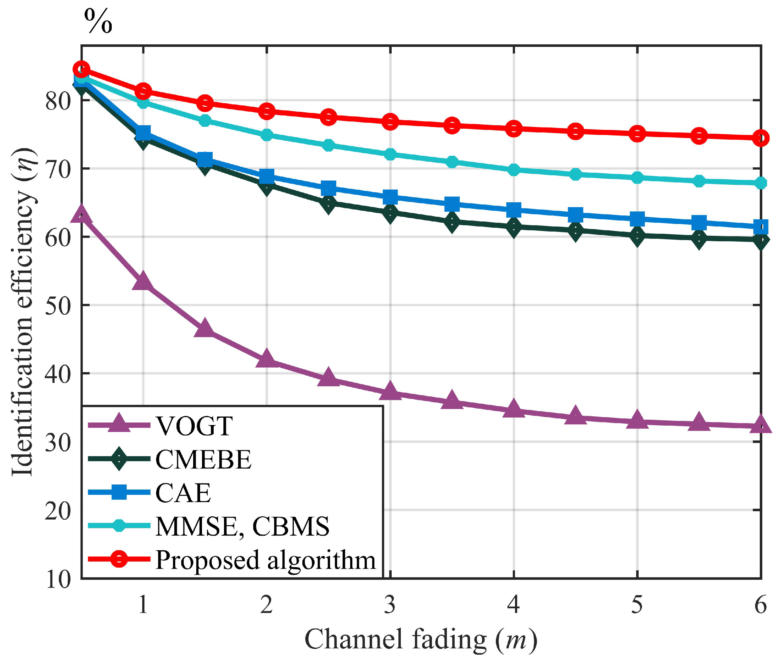
| VOGT | Small | - | 46.74 | 54.21 | 5.7462 | ||
| CMEBE | Small | 8.50 | 9.84 | 72.86 | 14.3671 | ||
| CAE | Small | 9.38 | 6.53 | 73.21 | 1.15 | ||
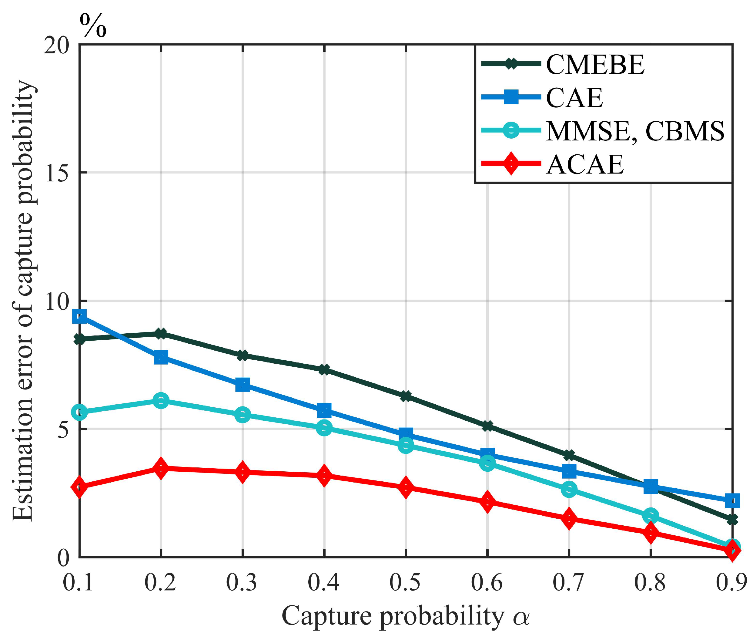
| MMSE, CBMS | Large | 5.65 | 2.77 | 79.66 | 32.61/33.13 | ||
| Proposed algorithm | Large | 2.73 | 1.94 | 81.31 | 15.42 |
Disclaimer/Publisher’s Note: The statements, opinions and data contained in all publications are solely those of the individual author(s) and contributor(s) and not of MDPI and/or the editor(s). MDPI and/or the editor(s) disclaim responsibility for any injury to people or property resulting from any ideas, methods, instructions or products referred to in the content. |
© 2023 by the authors. Licensee MDPI, Basel, Switzerland. This article is an open access article distributed under the terms and conditions of the Creative Commons Attribution (CC BY) license (https://creativecommons.org/licenses/by/4.0/).
Share and Cite
Xu, W.; Song, Z.; Sun, Y.; Wang, Y.; Lai, L. Capture-Aware Dense Tag Identification Using RFID Systems in Vehicular Networks. Sensors 2023, 23, 6792. https://doi.org/10.3390/s23156792
Xu W, Song Z, Sun Y, Wang Y, Lai L. Capture-Aware Dense Tag Identification Using RFID Systems in Vehicular Networks. Sensors. 2023; 23(15):6792. https://doi.org/10.3390/s23156792
Chicago/Turabian StyleXu, Weijian, Zhongzhe Song, Yanglong Sun, Yang Wang, and Lianyou Lai. 2023. "Capture-Aware Dense Tag Identification Using RFID Systems in Vehicular Networks" Sensors 23, no. 15: 6792. https://doi.org/10.3390/s23156792