
Flexible Antenna with Circular/Linear Polarization for Wideband Biomedical Wireless Communication
 , , and
Abstract
:1. Introduction
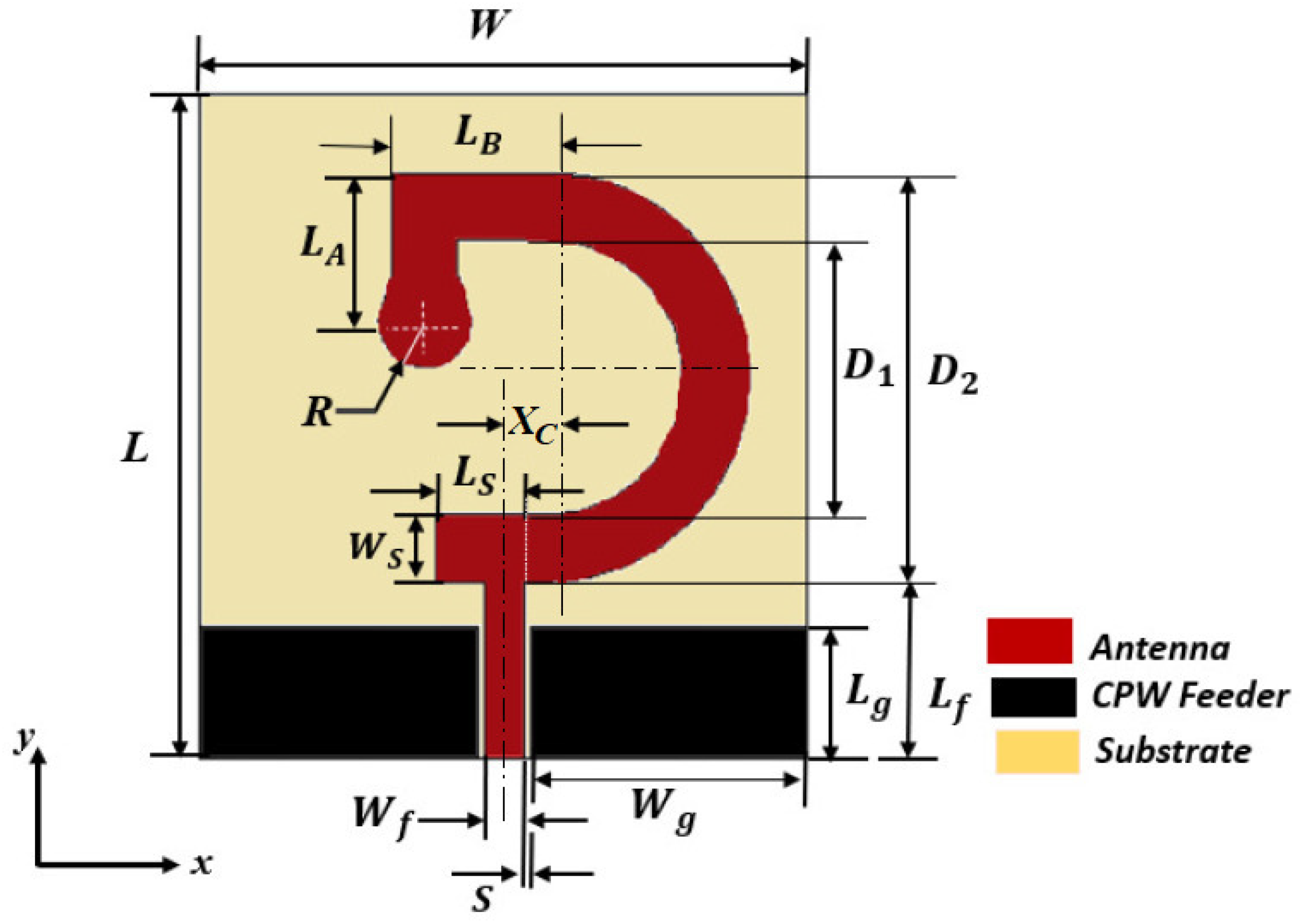
2. Antenna Design
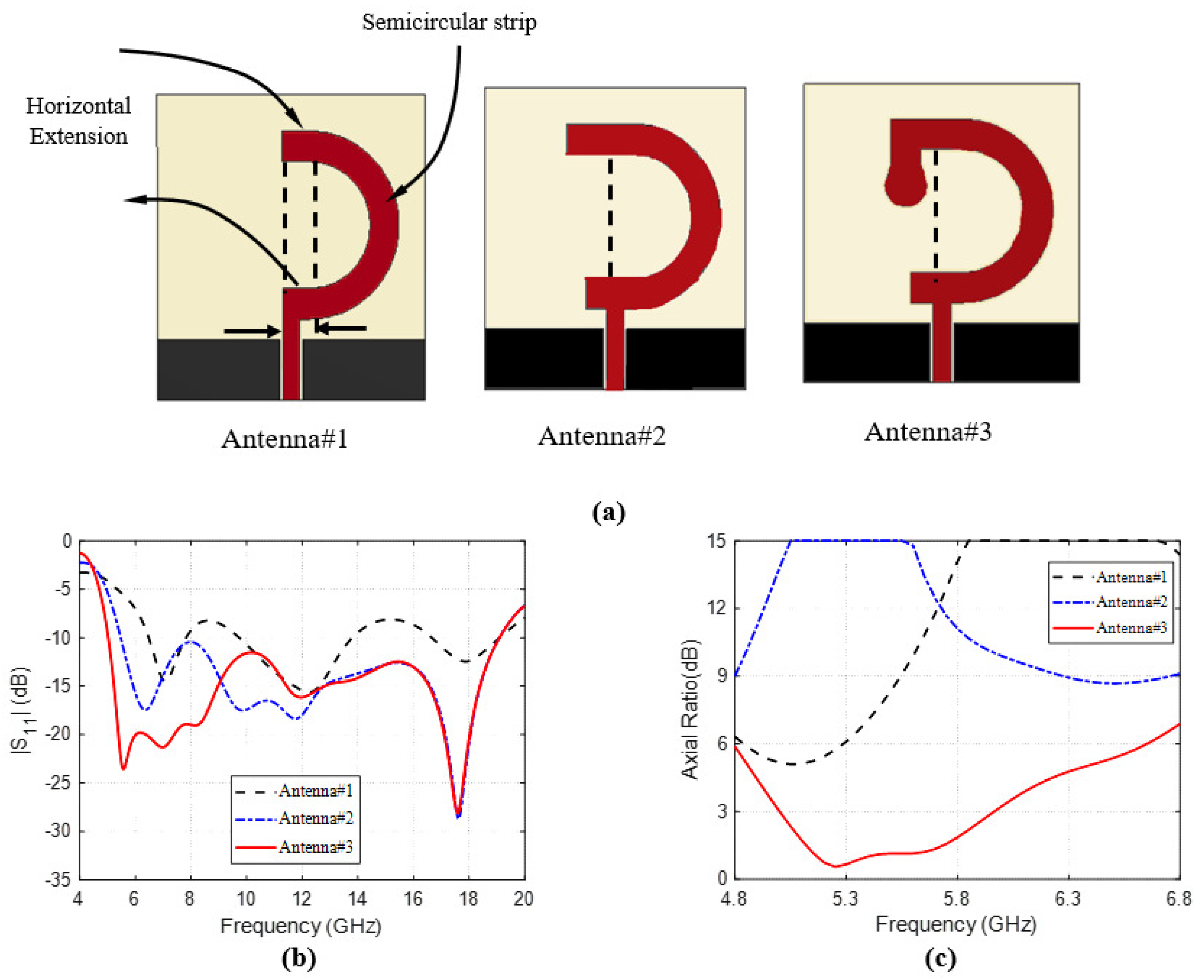
2.1. Evolution of the Antenna Design
2.2. Investigation of Optimal Dimensions
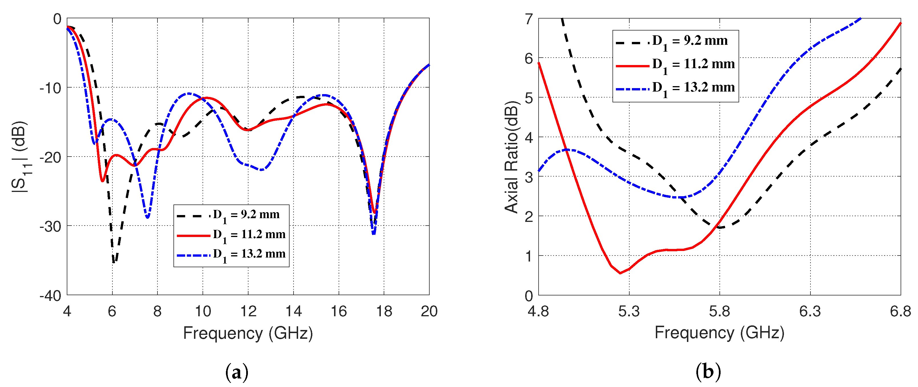
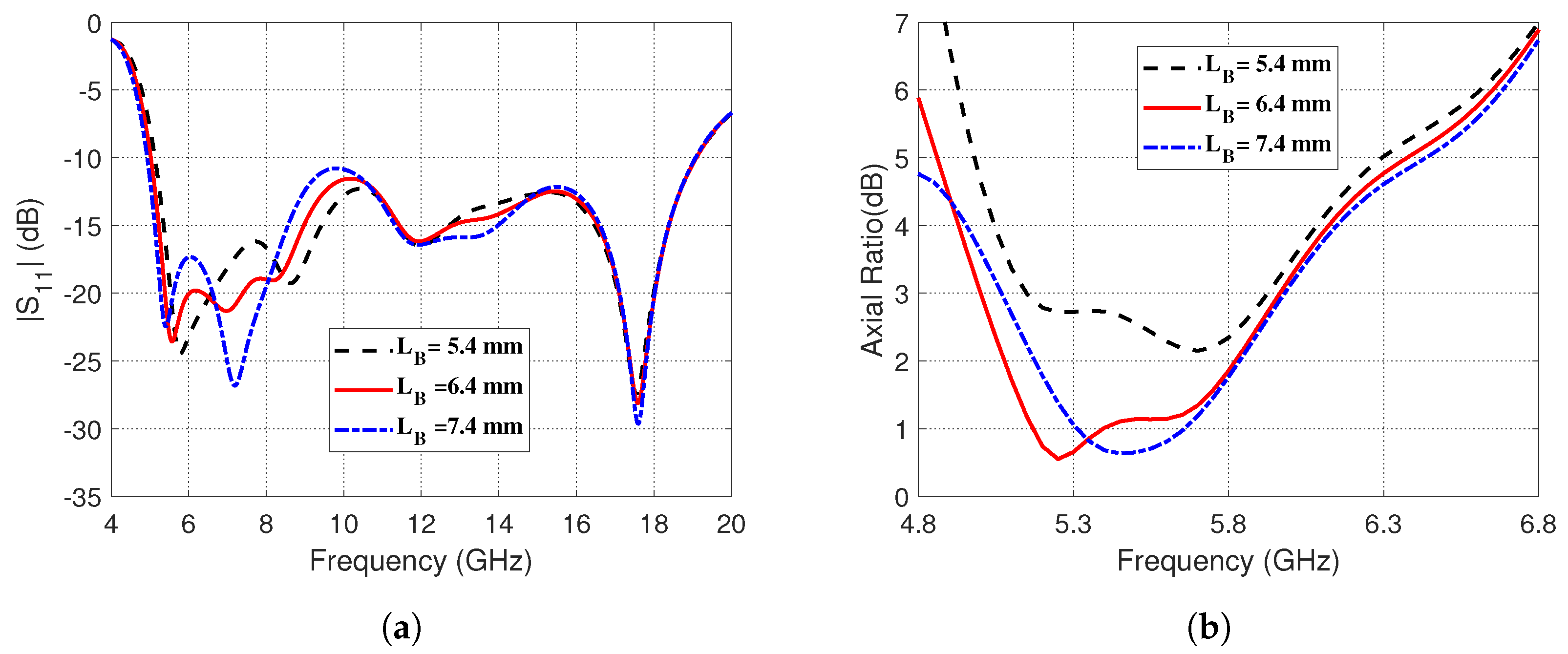
2.2.1. Effect of the Diameters of the Semicircular Strip
2.2.2. Effects of the Dimensions of the Corner-Shaped Extension of the Curved Strip
2.2.3. Influence of the Radius of the Circular Patch Termination
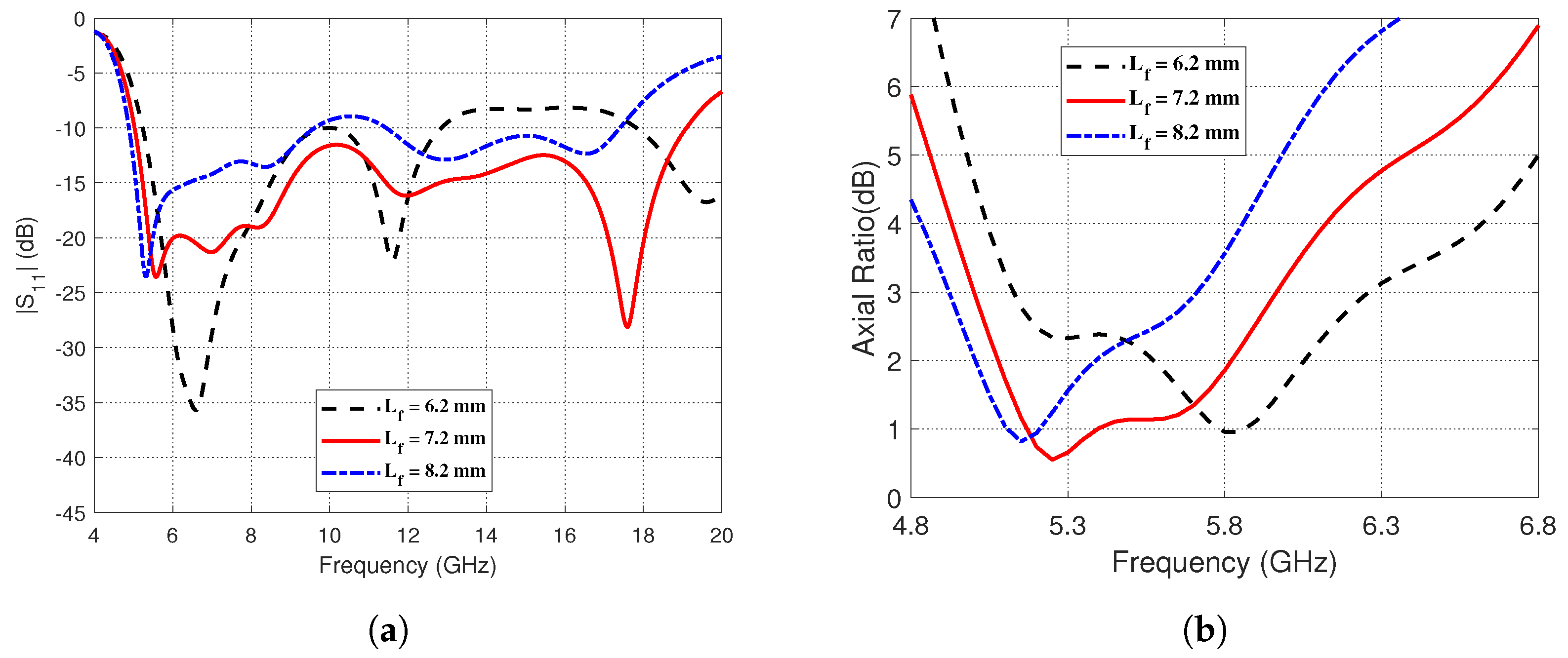
2.2.4. The Impact of Altering the Length of the CPW Central Strip Extension
2.2.5. Optimum Dimensional Parameters
3. Effect of Bend Stresses on the Inverted G-Shape CP Antenna Characteristics
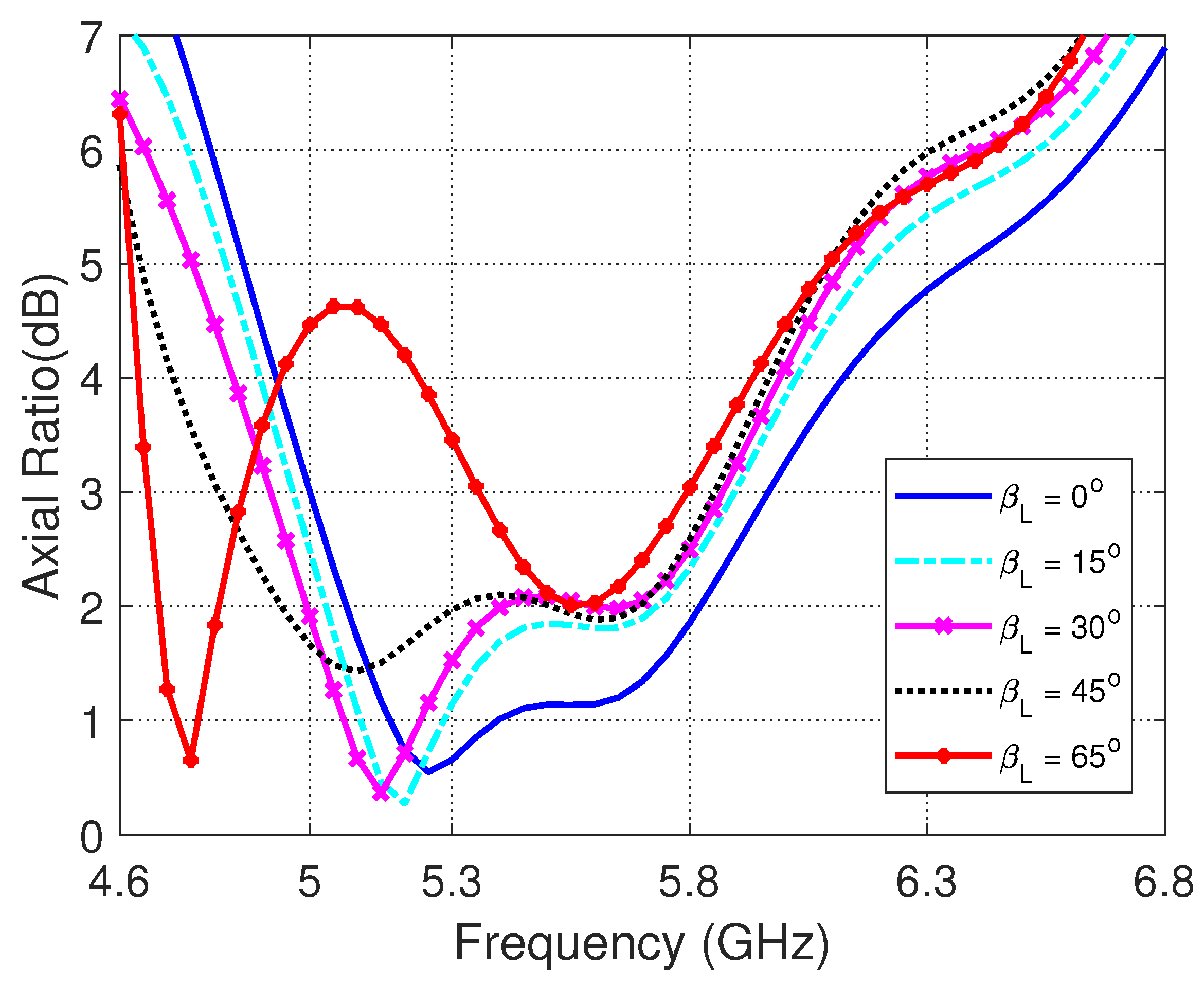
3.1. Effects of Bending the Antenna in the Longitudinal Plane on the Impedance Matching and Axial Ratio
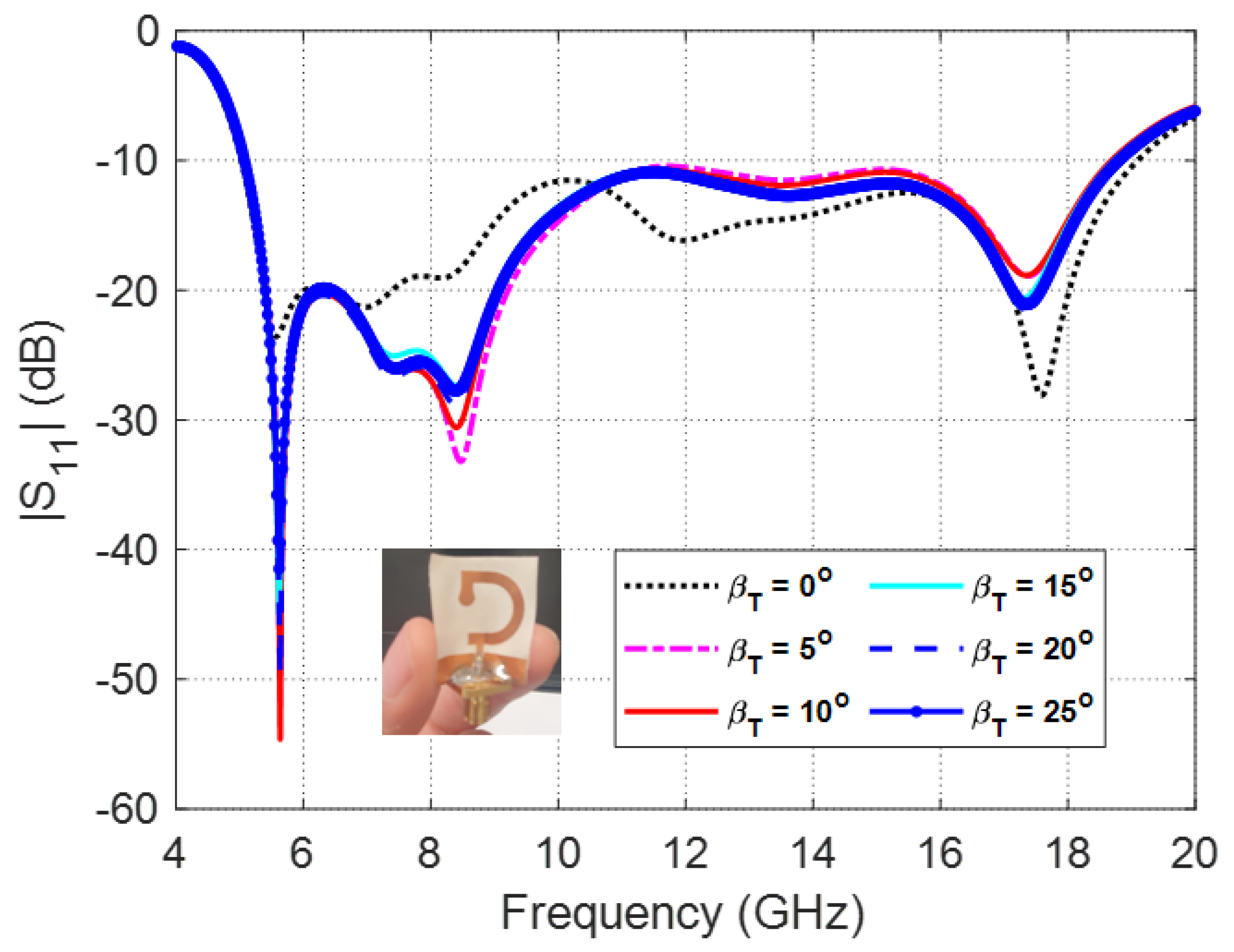
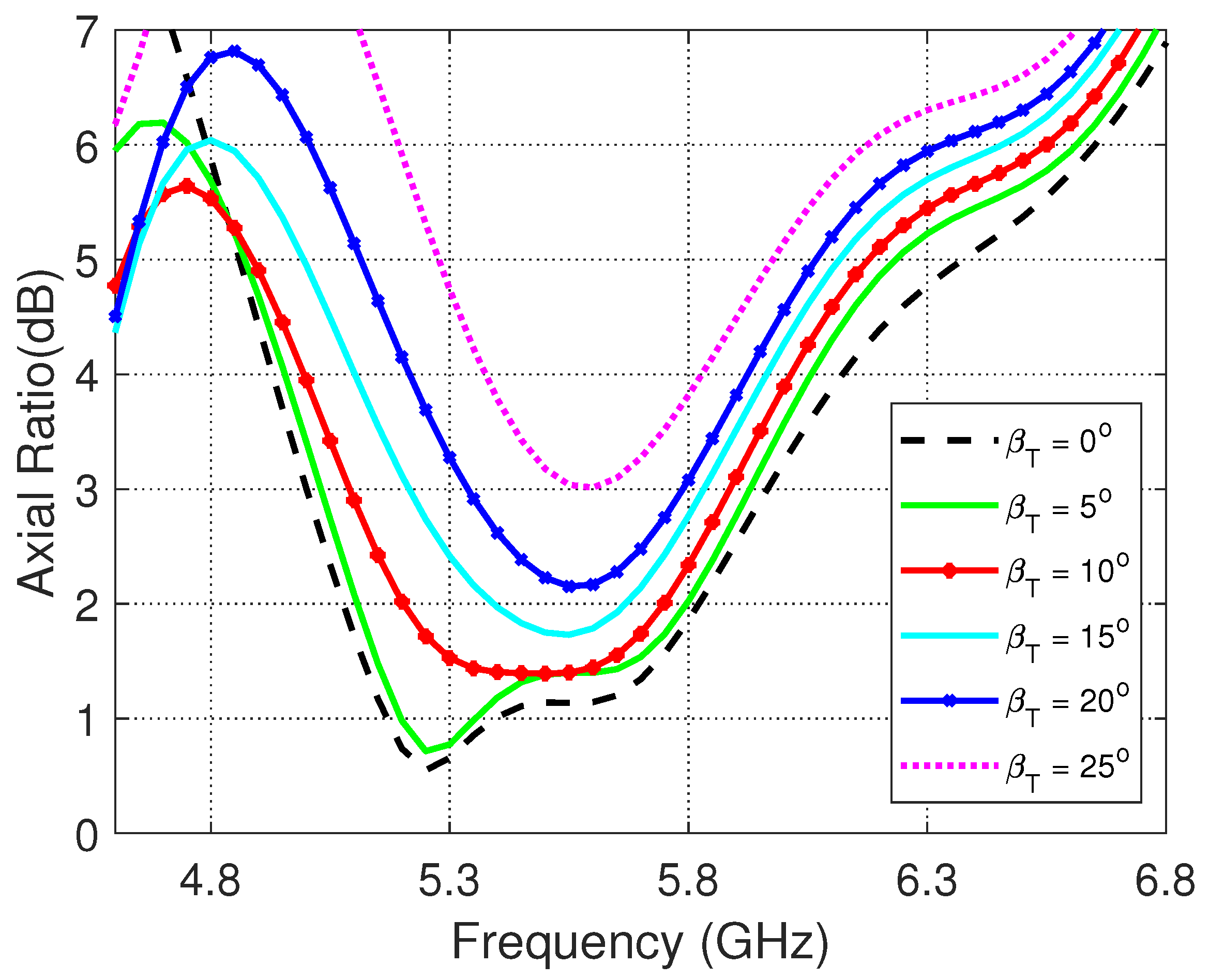
3.2. Effects of Bending the Antenna in the Transverse Plane on the Impedance Matching and Axial Ratio
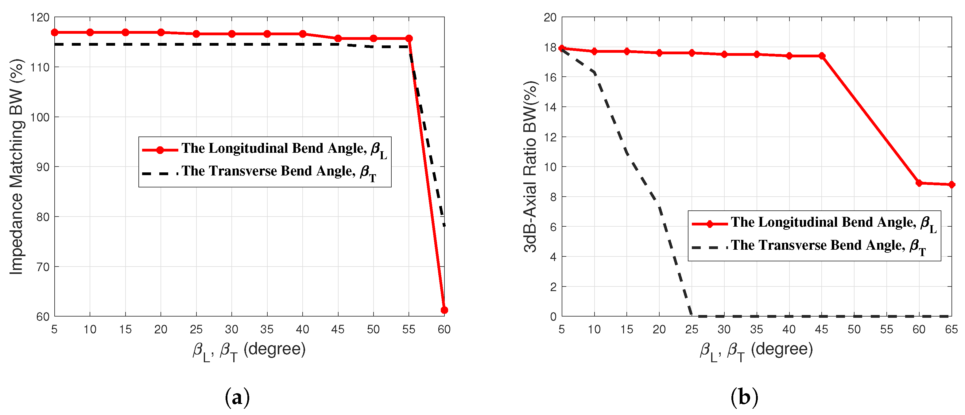
3.3. Effect of Bending the Antenna on the Impedance Matching Bandwidth
3.4. Effect of Bending the Antenna on the 3dB Axial Ratio Bandwidth
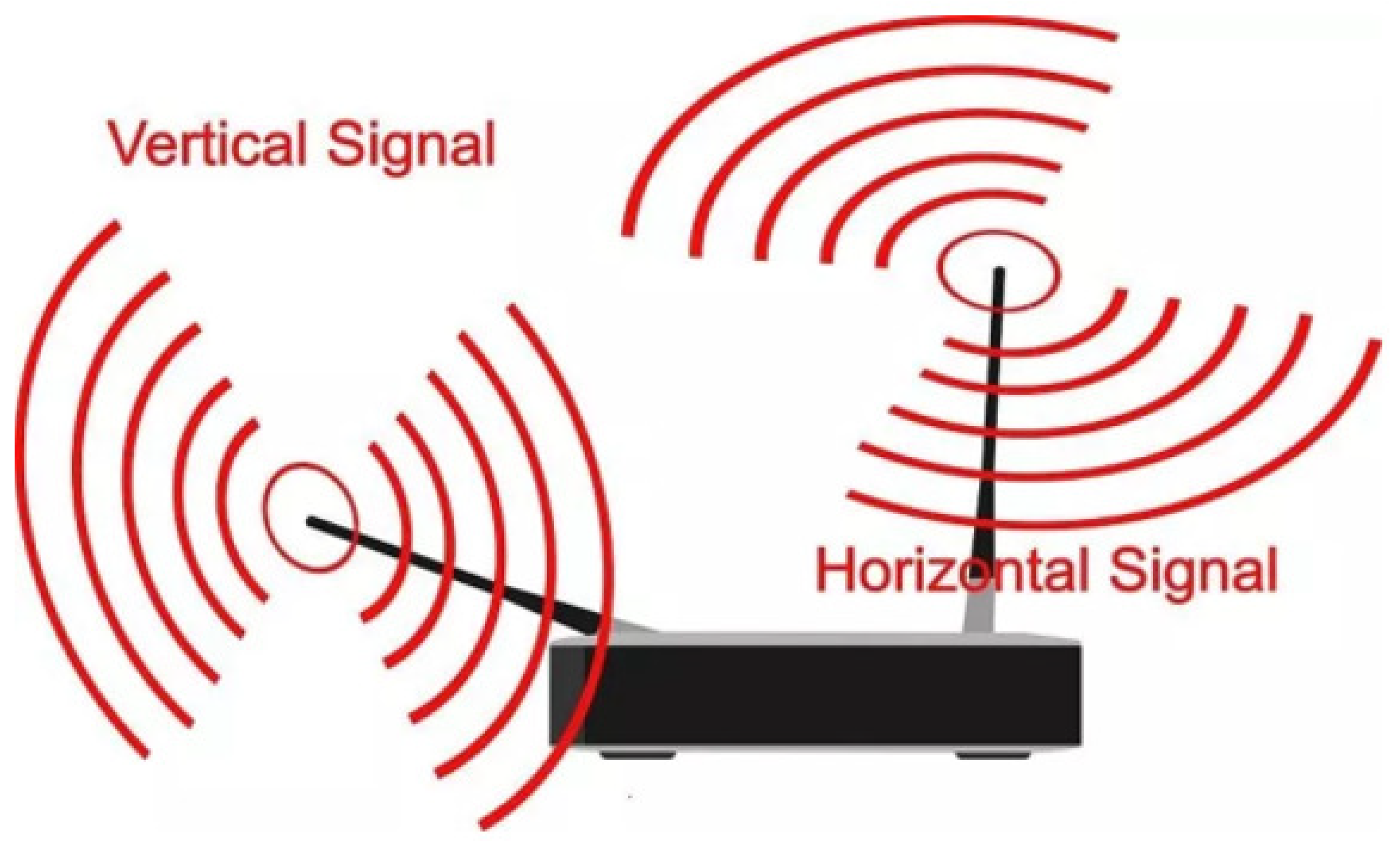
4. Mechanism of Circular Polarization
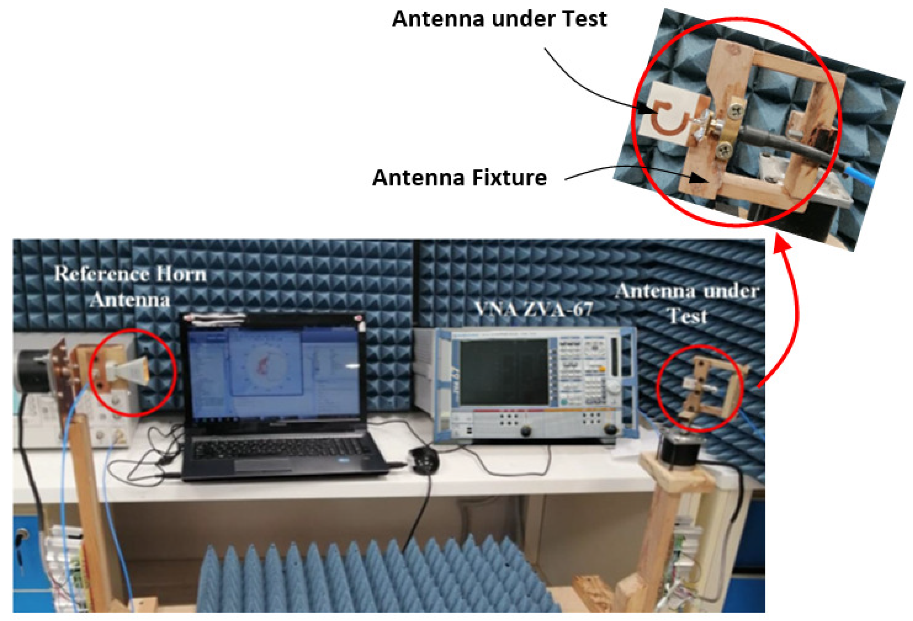
5. Procedure for Measurement of the Radiation Patterns, Gain, and Efficiency
5.1. Measurement of the Radiation Pattern
5.2. Measurement of the Antenna Gain
5.3. Measurement of the Antenna Efficiency
5.3.1. Total Antenna Efficiency
5.3.2. Antenna Radiation Efficiency
6. Experimental Results and Discussions
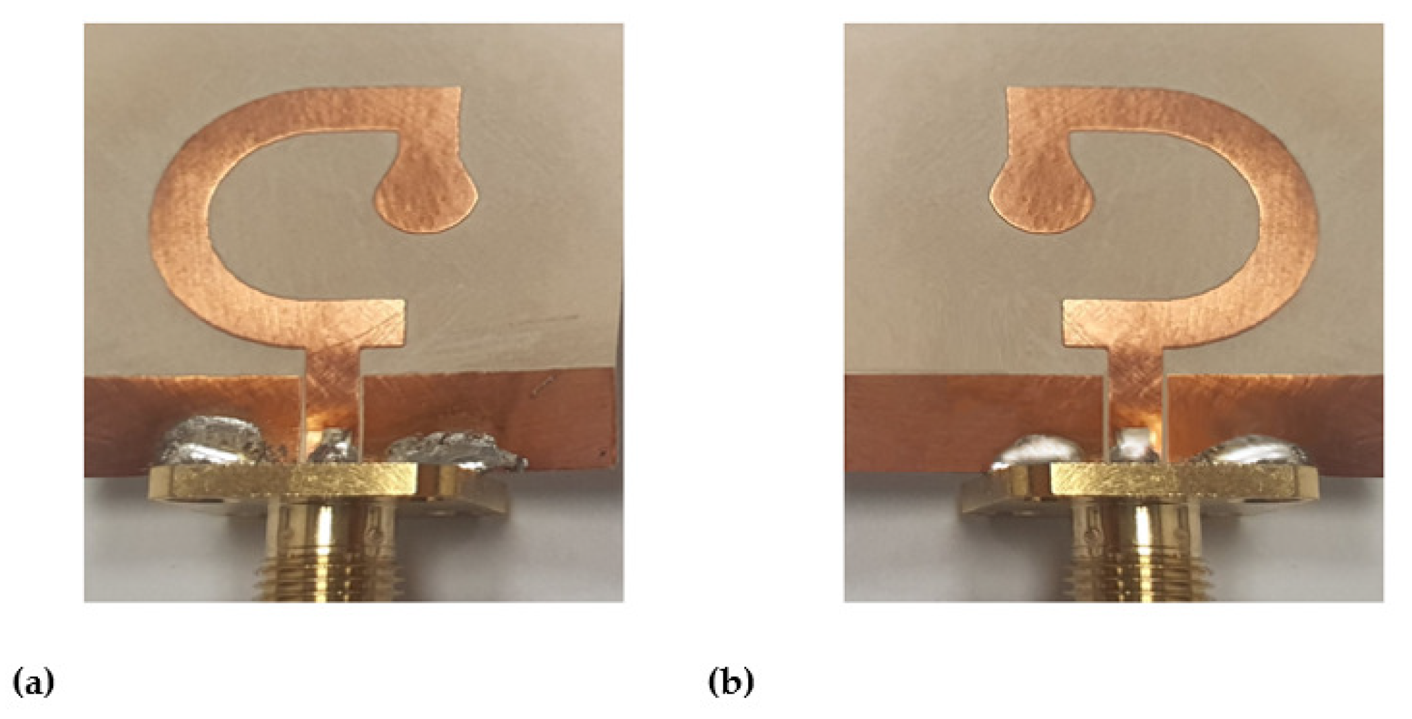
6.1. Fabrication and Measurements of Reflection Coefficient
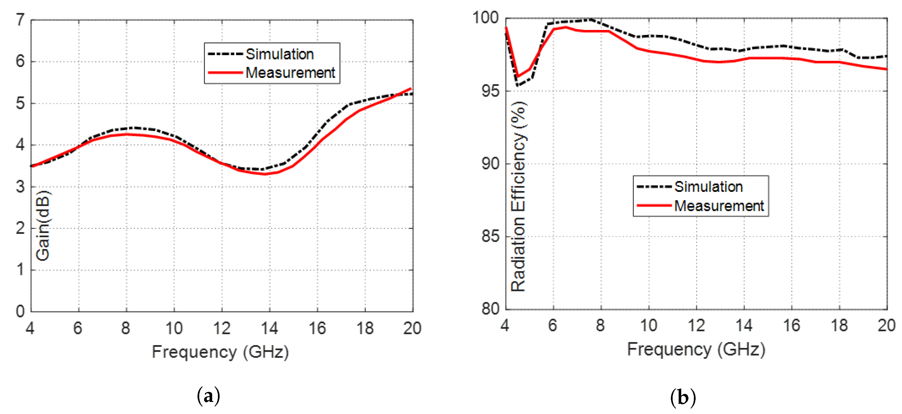
6.2. Gain and Radiation Efficiency
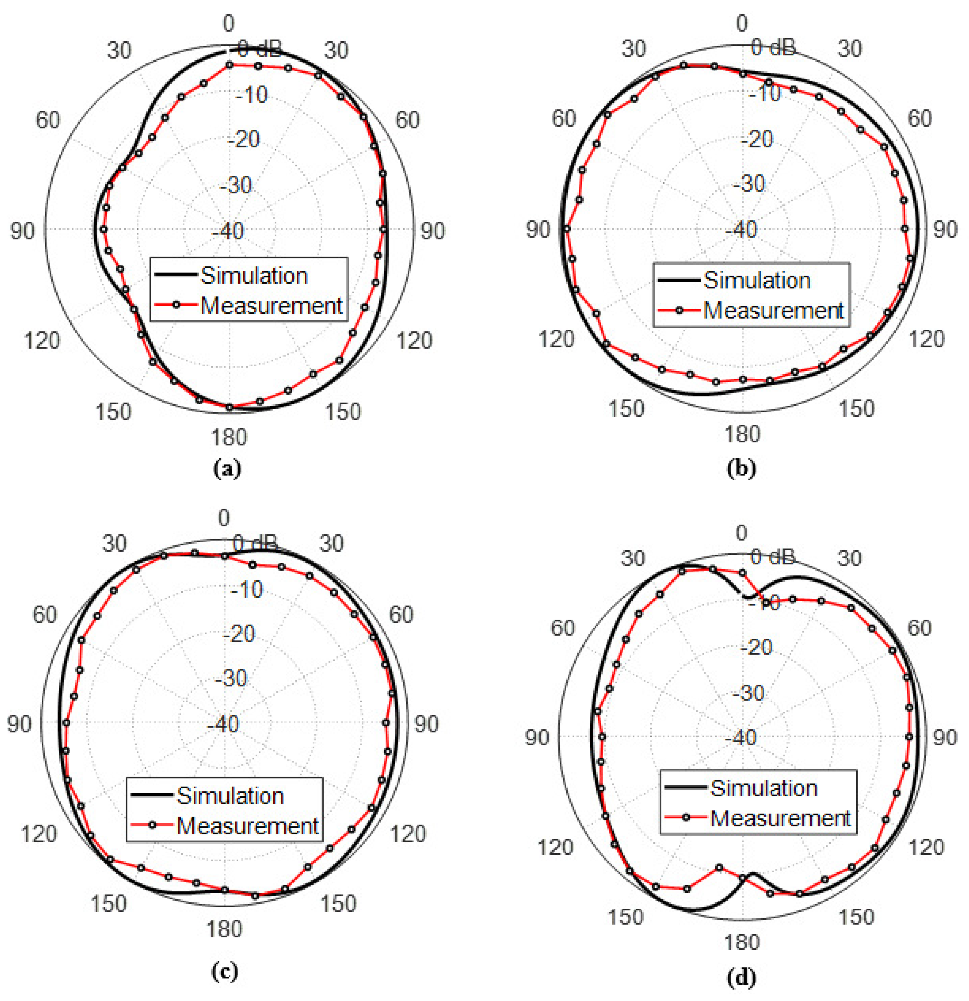
6.3. Radiation Patterns
6.3.1. Circularly Polarized Radiated Fields
6.3.2. Linearly Polarized Radiated Fields
6.4. Summary of Comparative Performance
7. Conclusions
Author Contributions
Funding
Data Availability Statement
Acknowledgments
Conflicts of Interest
Abbreviations
| CP | Circularly Polarized |
| CPW | Co-planar Waveguide |
| WBAN | Wireless Body Area Network |
| UWB | Ultra-wideband |
| RHCP | Right-hand CP |
| LHCP | Left-hand CP |
| AR | Axial Ratio |
| BDR | Bandwidth-Dimension Ratio |
| VNA | Vector Network Analyzer |
References
- Yang, H.C.; Liu, X.Y.; Fan, Y.; Tentzeris, M.M. Flexible circularly polarized antenna with axial ratio bandwidth enhancement for off-body communications. IET Microwaves Antennas Propag. 2021, 15, 754–767. [Google Scholar] [CrossRef]
- Ullah, U.; Mabrouk, I.B.; Koziel, S. A compact circularly polarized antenna with directional pattern for wearable off-body communications. IEEE Antennas Wirel. Propag. Lett. 2019, 18, 2523–2527. [Google Scholar] [CrossRef]
- Anderson, R.M.; Turner, H.C.; Farrell, S.H.; Truscott, J.E. Flexible antennas: A review. Micromachines 2020, 11, 847. [Google Scholar]
- Ahmad, S.; Khabba, A.; Ghaffar, A.; Li, X.J. A Compact Wideband Flexible Circularly Polarized Implantable Antenna for Biotelemetry Applications. In Proceedings of the IEEE International Symposium on Antennas and Propagation and USNC-URSI Radio Science Meeting (APS/URSI), Marina Bay Sands, Singapore, 4–10 December 2021; pp. 695–696. [Google Scholar]
- Särestöniemi, M.; Sonkki, M.; Myllymäki, S.; Pomalaza-Raez, C. Wearable flexible antenna for UWB on-body and implant communications. Telecom 2021, 2, 19. [Google Scholar] [CrossRef]
- Farahat, A.E.; Hussein, K.F.A. Wearable Button-Like Dual-Band Central Antenna for Wireless Bodyarea Networks. Prog. Electromagn. Res. B 2021, 90, 21–41. [Google Scholar] [CrossRef]
- Farahat, A.E.; Hussein, K.F.A. Dual-band dual-mode monopole/spiral central antenna for WBAN applications. Microw. Opt. Technol. Lett. 2022, 64, 1401–1406. [Google Scholar] [CrossRef]
- Poffelie, L.A.Y.; Soh, P.J.; Yan, S.; Vandenbosch, G.A.E. A high-fidelity all-textile UWB antenna with low back radiation for off-body WBAN applications. IEEE Trans. Antennas Propag. 2015, 64, 757–760. [Google Scholar] [CrossRef]
- Federal Communications Commission. FCC Report and Order for Part 15 Acceptance of Ultra Wideband (UWB) Systems from 3.1 to 10.6 GHz; FCC: Washington, DC, USA, 2002; pp. 1–10. [Google Scholar]
- Balanis, C.A. Antenna Theory and Design, 3rd ed.; Wiley: New York, NY, USA, 2005. [Google Scholar]
- Shichang, S.S.; Luo, Q.; Zhu, F. Circularly Polarized Antennas; Wiley-IEEE Press: Hoboken, NJ, USA, 2014. [Google Scholar]
- Nadeem, I.; Alibakhshikenari, M.; Babaeian, F.; Althuwayb, A.; Virdee, B.; Azpilicueta, L.; Khan, S.; Huynen, I.; Falcone, F.; Denidni, T.; et al. A comprehensive survey on ‘circular polarized antennas’ for existing and emerging wireless communication technologies. J. Phys. Appl. Phys. 2022, 55, 033002. [Google Scholar] [CrossRef]
- Trinh, L.H.; Truong, N.V.; Ferrero, F. Low cost circularly polarized antenna for IoT space applications. Electronics 2020, 9, 1564. [Google Scholar] [CrossRef]
- Mondal, T.; Maity, S.; Ghatak, R.; Bhadra, C.; Sekhar, R. Design and analysis of a wideband circularly polarised perturbed psi-shaped antenna. IET Microwaves Antennas Propag. 2018, 12, 1582–1586. [Google Scholar] [CrossRef]
- Yassin, M.E.; Mohamed, H.A.; Abdallah, E.A.F.; El-Hennawy, H.S. Circularly polarized wideband-to-narrowband switchable antenna. IEEE Access 2019, 7, 36010–36018. [Google Scholar] [CrossRef]
- Deegwal, J.K.; Sharma, V. Dual Band Circular Polarized Printed Dipole Antenna for S and C Band Wireless Applications. Prog. Electromagn. Res. C 2020, 105, 129–146. [Google Scholar]
- Zhai, H.; Yang, D.; Xi, L.; Feng, D. A new CPW-fed broadband circularly polarized printed monopole antenna for UWB application. Microw. Opt. Technol. Lett. 2018, 60, 364–369. [Google Scholar] [CrossRef]
- Saraswat, K.; Harish, A.R. Dual-band CP coplanar waveguide-fed split-ring resonator-loaded G-shaped slot antenna with wide-frequency ratio. IET Microwaves Antennas Propag. 2018, 12, 1920–1925. [Google Scholar] [CrossRef]
- Li, G.; Zhai, H.; Ma, X.; Li, T.; Liang, C. Design of a CPW-fed slot antenna with small size and ultra-broadband circularly polarized radiation. J. Electromagn. Waves Appl. 2014, 28, 1212–1220. [Google Scholar] [CrossRef]
- Liu, X.; Wang, H.; Yang, X.; Wang, J. Quad-band circular polarized antenna for GNSS, 5G and WIFI-6E applications. Electronics 2022, 11, 1133. [Google Scholar] [CrossRef]
- Babu, B.A.; Madhav, B.T.P.; Vineel, B.; Chandini, G.; Amrutha, C.; Rao, M.C. Design and Analysis of a Circularly polarized flexible, compact and transparent antenna for Vehicular Communication Applications. J. Physics Conf. Ser. 2021, 1804, 012192. [Google Scholar] [CrossRef]
- Al-Gburi, A.J.A.; Zakaria, Z.; Alsariera, H.; Akbar, M.F.; Ibrahim, I.M.; Ahmad, K.S.; Ahmad, S.; Al-Bawri, S.S. Broadband Circular Polarised Printed Antennas for Indoor Wireless Communication Systems: A Comprehensive Review. Micromachines 2022, 13, 1048. [Google Scholar] [CrossRef]
- Banerjee, U.; Karmakar, A.; Saha, A. A review on circularly polarized antennas, trends and advances. Int. J. Microw. Wirel. Technol. 2020, 12, 922–943. [Google Scholar] [CrossRef]
- Reddy, V.; Sarma, N. Single feed circularly polarized poly fractal antenna for wireless applications. Int. J. Comput. Inf. Eng. 2014, 11, 1710–1713. [Google Scholar]
- Sharma, V.; Jhajharia, T. Square slot antenna for wide circularly polarized bandwidth and axial ratio beamwidth. Electr. Control. Commun. Eng. 2021, 17, 1–11. [Google Scholar] [CrossRef]
- Kumar, M.; Nath, V. A circularly polarized printed elliptical wide-slot antenna with high bandwidth-dimension-ratio for wireless applications. Wirel. Netw. 2020, 17, 5485–5499. [Google Scholar] [CrossRef]
- AboEl-Hassan, M.; Hussein, K.F.; Awadalla, K.H. A novel microstrip antenna with L-shaped slots for circularly polarized satellite applications. Microw. Opt. Technol. Lett. 2020, 62, 839–844. [Google Scholar] [CrossRef]
- Chen, Z.N.; Qing, X. Slotted microstrip antennas for circular polarization with compact size. IEEE Antennas Propag. Mag. 2013, 55, 124–137. [Google Scholar]
- Ahmad, S.; Manzoor, B.; Naseer, S.; Ghaffar, A.; Hussein, M. A Flexible Broadband CPW-Fed Circularly Polarized Biomedical Implantable Antenna with Enhanced Axial Ratio Bandwidth. Res. Sq. 2021. preprint. [Google Scholar] [CrossRef]
- Chaudhary, P.; Kumar, A.; Mittra, R. Quadrilateral-shaped wideband circularly polarized CPW-fed monopole antenna. In Proceedings of the URSI Asia-Pacific Radio Science Conference (AP-RASC), New Delhi, India, 9–15 March 2019; pp. 1–4. [Google Scholar]
- Ullah, U.; Koziel, S. A novel coplanar-strip-based excitation technique for design of broadband circularly polarization antennas with wide 3dB Axial Ratio beamwidth. IEEE Trans. Antennas Propag. 2019, 67, 4224–4229. [Google Scholar] [CrossRef]
- Kumar, M.; Nath, V. Circularly polarized microstrip-line-fed antenna with rotated elliptical slot serving satellite communications. IEEE Trans. Antennas Propag. 2020, 110, 1443–1458. [Google Scholar] [CrossRef]
- Liang, C.-F.; Lyu, Y.-P.; Chen, D.; Cheng, C.-H. Wideband Circularly Polarized Stacked Patch Antenna Based on TM11 and TM10. IEEE Trans. Antennas Propag. 2021, 70, 2459–2467. [Google Scholar] [CrossRef]
- Kumar, R.; Chaudhary, R.K. Investigation of higher order modes excitation through F-shaped slot in rectangular dielectric resonator antenna for wideband circular polarization with broadside radiation characteristics. Int. J. Microw.-Comput.-Aided Eng. 2018, 28, e21281. [Google Scholar] [CrossRef]
- Sayem, A.S.M.; Simorangkir, R.B.V.B.; Esselle, K.P.; Lalbakhsh, A.; Gawade, D.R.; O’Flynn, B.; Buckley, J.L. Flexible and transparent circularly polarized patch antenna for reliable unobtrusive wearable wireless communications. Sensors 2022, 22, 1276. [Google Scholar] [CrossRef] [PubMed]
- Xia, Y.; Yuan, M.; Dobrea, A.; Li, C.; Heidari, H.; Mottram, N.; Ghannam, R. Reconfigurable Wearable Antenna for 5G Applications using Nematic Liquid Crystals. arXiv 2022, arXiv:2212.08622. [Google Scholar]
- Mostafa, A.; Ibrahim, F.; Ahmed, H.; Yassin, M. Wideband Energy Harvesting System Based on Circularly Polarized Monopole Antenna. Int. Undergrad. Res. Conf. 2021, 5, 403–408. [Google Scholar]
- Li, J.; Jiang, Y.; Zhao, X. Circularly polarized wearable antenna based on NinjaFlex-embedded conductive fabric. Int. J. Antennas Propag. 2019, 2019, 3059480. [Google Scholar] [CrossRef] [Green Version]
- Fernández-Prades, C.; Rogier, H.; Collado, A.; Tentzeris, M.M. Flexible substrate antennas. Int. J. Antennas Propag. 2012, 2012, 1–2. [Google Scholar] [CrossRef]
- Virothu, S.; Anuradha, M.S. Flexible CP diversity antenna for 5G cellular Vehicle-to-Everything applications. AEU-Int. J. Electron. Commun. 2022, 152, 154248. [Google Scholar] [CrossRef]
- Birwal, A.; Singh, S.; Kanaujia, B.K.; Kumar, S. Broadband CPW-fed circularly polarized antenna for IoT-based navigation system. Int. J. Microw. Wirel. Technol. 2019, 11, 835–843. [Google Scholar] [CrossRef]
- Kirtania, S.G.; Younes, B.A.; Hossain, A.R.; Karacolak, T.; Sekhar, P.K. CPW-fed flexible ultra-wideband antenna for IoT applications. Micromachines 2021, 12, 453. [Google Scholar] [CrossRef]
- Zhang, R.; Liu, J.; Wang, Y.; Luo, Z.; Zhang, B.; Duan, J. Flexible wearable composite antennas for global wireless communication systems. Sensors 2021, 21, 6083. [Google Scholar] [CrossRef]
- Fahmy, W.M.; Farahat, A.E.; Hussein, K.F.A.; Ammar, A.A. High Q-factor bandstop filter based on CPW resonator broadside-coupled to CPW through-line. Prog. Electromagn. Res. B 2020, 86, 121–138. [Google Scholar] [CrossRef] [Green Version]
- Fahmy, W.M.; Farahat, A.E.; Hussein, K.F.A.; Ammar, A.A. Dual-Band Bandpass Filter Optimized for High Q-Factor. Appl. Comput. Electromagn. Soc. J. (ACES) 2021, 36, 398–410. [Google Scholar] [CrossRef]
- Available online: https://wireless-instruments.com/lte-wimax-bands/ (accessed on 11 May 2023).
- Ahmad, S.; Cherif, N.; Naseer, S.; Ijaz, U.; Faouri, Y.S.; Ghaffar, A.; Hussein, M. A wideband circularly polarized CPW-fed substrate integrated waveguide based antenna array for ISM band applications. Heliyon 2022, 8, e10058. [Google Scholar] [CrossRef]
- Venkateswara Rao, M.; Madhav, B.T.P.; Anilkumar, T.; Prudhvinadh, B. Circularly polarized flexible antenna on liquid crystal polymer substrate material with metamaterial loading. Microw. Opt. Technol. Lett. 2020, 62, 866–874. [Google Scholar] [CrossRef]
- Pakkathillam, J.K.; Kanagasabai, M. Circularly polarized broadband antenna deploying fractal slot geometry. IEEE Antennas Wirel. Propag. Lett. 2015, 14, 1286–1289. [Google Scholar] [CrossRef]
- Kumar, Y.; Gangwar, R.K.; Kanaujia, B.K. Characterization of CP radiations in a planar monopole antenna using tuning fork fractal slot for LTE band13/Wi-Max and Wi-Fi applications. IEEE Access 2020, 8, 127123–127133. [Google Scholar] [CrossRef]
- Hossain, A.R.; Karacolak, T. CPW-Fed Compact Circularly Polarized Flexible Antenna for C Band Applications. In Proceedings of the 2023 United States National Committee of URSI National Radio Science Meeting (USNC-URSI NRSM), Online, 10–14 January 2023; pp. 246–247. [Google Scholar]
- Samsuzzaman, M.; Islam, M.T. Circularly polarized broadband printed antenna for wireless applications. Sensors 2018, 18, 4261. [Google Scholar] [CrossRef] [PubMed] [Green Version]


| Mode of Operation | Function of the Antenna | Frequency Range | Polarization |
|---|---|---|---|
| On-body | Communicate with the biosensor | 6–19 GHz | Linear |
| antennas for biotelemetry | |||
| Off-body | Retransmit biotelemetry to | 5–6 GHz | Circular |
| WiMAX/WLAN antennas |
| Parameter | W | L | D | D | R | L | h | W |
|---|---|---|---|---|---|---|---|---|
| Value (mm) | 25 | 27 | 11.2 | 16.6 | 1.9 | 4.6 | 0.13 | 2.7 |
| Parameter | L | L | W | L | L | W | S | X |
| Value (mm) | 6 | 6.4 | 11.4 | 5.4 | 7.2 | 1.6 | 0.3 | 1.8 |
| Name of the Allocated Band | WiMAX | WLAN |
|---|---|---|
| 700 MHz band | 470–862 MHz | – |
| 1.4 GHz band | 1.390–1.435 GHz | – |
| 2.3 GHz band | 2.300–2.400 GHz | – |
| 2.4 GHz band | 2.498–2.800 GHz | – |
| 2.5 GHz band | – | 2.400–2.484 |
| 3.5 GHz band | 3.300–3.800 GHz | – |
| 3.6 GHz band | – | 3.675–3.890 |
| 5 GHz band | 4.900–5.980 GHz | 4.915–5.925 |
| Work | Dimensions ) | Frequency Band (GHz) | % BW for Impedance Matching | Radiation Efficiency | Gain (dBi) | % BW for 3dB-AR | Substrate |
|---|---|---|---|---|---|---|---|
| [1] | 5.6–6.1 | NA | 7.2 | Flexible | |||
| [4] | 1.4–1.8 | NA | −1.25 | Flexible | |||
| [21] | 5.2–6.8 | NA | 2.94 | Flexible | |||
| [30] | 4.8–16 | NA | 3.33 | Rigid FR-4 | |||
| [47] | 2.1–3.6 | 4.5 | Flexible | ||||
| [48] | 5.5–7 | NA | NA | Flexible | |||
| [49] | 3.4–7 | 6.5 | Rigid FR-4 | ||||
| [50] | 1.8–2.4 | NA | 3.95 | Rigid FR-4 | |||
| [51] | 3.8–4.5 | 3.1 | Flexible | ||||
| [52] | 2.22–9.92 | 3.98 | Rigid FR-4 | ||||
| Present | 4.9–19 | 5.37 | Flexible |
Disclaimer/Publisher’s Note: The statements, opinions and data contained in all publications are solely those of the individual author(s) and contributor(s) and not of MDPI and/or the editor(s). MDPI and/or the editor(s) disclaim responsibility for any injury to people or property resulting from any ideas, methods, instructions or products referred to in the content. |
© 2023 by the authors. Licensee MDPI, Basel, Switzerland. This article is an open access article distributed under the terms and conditions of the Creative Commons Attribution (CC BY) license (https://creativecommons.org/licenses/by/4.0/).
Share and Cite
Yassin, M.E.; Hussein, K.F.A.; Abbasi, Q.H.; Imran, M.A.; Mohassieb, S.A. Flexible Antenna with Circular/Linear Polarization for Wideband Biomedical Wireless Communication. Sensors 2023, 23, 5608. https://doi.org/10.3390/s23125608
Yassin ME, Hussein KFA, Abbasi QH, Imran MA, Mohassieb SA. Flexible Antenna with Circular/Linear Polarization for Wideband Biomedical Wireless Communication. Sensors. 2023; 23(12):5608. https://doi.org/10.3390/s23125608
Chicago/Turabian StyleYassin, Mohammed E., Khaled F. A. Hussein, Qammer H. Abbasi, Muhammad A. Imran, and Shaimaa A. Mohassieb. 2023. "Flexible Antenna with Circular/Linear Polarization for Wideband Biomedical Wireless Communication" Sensors 23, no. 12: 5608. https://doi.org/10.3390/s23125608