
Spherical Robots for Special Purposes: A Review on Current Possibilities

 , , , , , , and
Abstract
:1. Introduction
1.1. Applications of Spherical Robots
- the outer shell protects the whole system of the robots,
- the smoothness of movement,
- great power effectivity,
- the motion can be omnidirectional due to the design,
- the possibility of movement on water or throwing a robot, and
- the robot cannot be overturned.
- the small maximum torque,
- problems with movement on uneven and steep terrain,
- limitations in the use of environmental sensors,
- the size of the shell depends on the construction of the inner driving mechanism, and
- complicated design.
2. Driving Mechanism
- direct driving method,
- gravity driving method, and
- angular momentum driving method.
2.1. Kinematics of a Spherical Robot
2.2. Direct Driving Method
2.2.1. Single Wheel
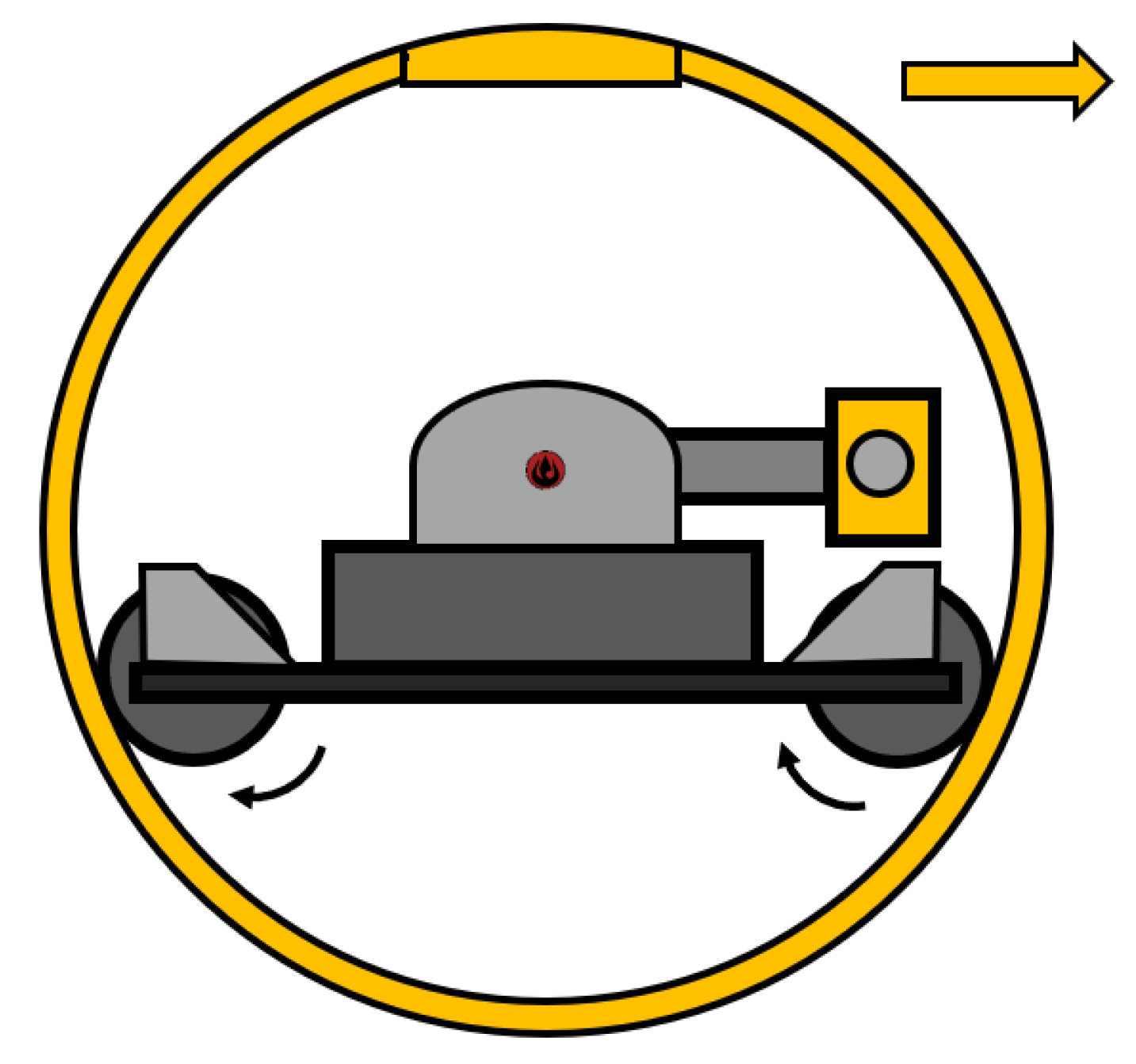
2.2.2. Hamster Ball
2.3. The Gravity Driving Method
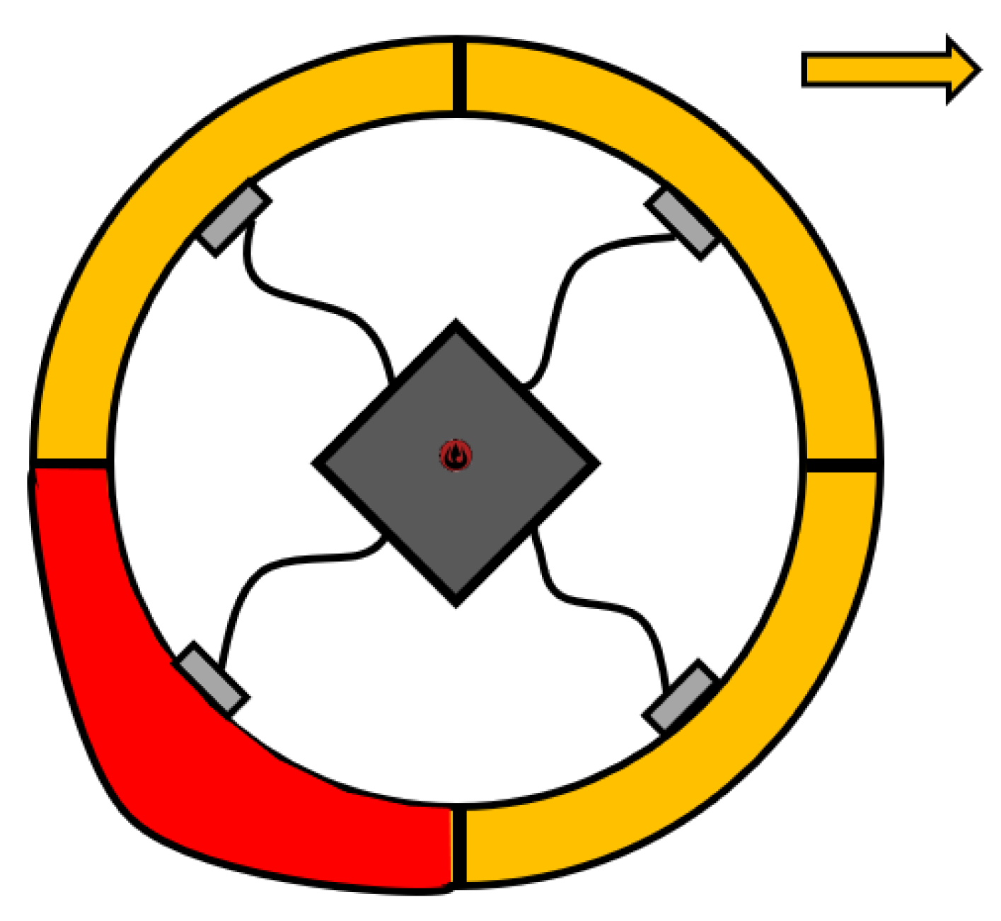
2.3.1. Shifting Masses
2.3.2. Pendulum
2.3.3. Double Pendulum
2.3.4. Gimbal Mechanism
2.3.5. Dynamics
2.4. The Angular Momentum Driving Method
Dynamics
2.5. Some Other Types of Driving Mechanisms
Dynamics
2.6. Comparison of Each Mechanism
3. Inertial Sensors
- Quaternion:where are the coordinates of unit vector expressing arbitrary axis of rotation and is the angle of rotation around that axis.
- Rotation matrix T: with dimensions 3×3, which defines the transformation between the robot’s local coordinate system and the global coordinate system, or vice versa.
- Euler angles: a sequence of 3 rotations around fundamental axes of the robot’s coordinate system, e.g., Z-Y-X, named yaw , pitch , and roll .
- Mechanical rotating gyroscope: may directly measure the attitude of the robot. The oldest type, widely used in aircraft and missile control systems. It is based on the principle that the attitude of a flywheel in a gimbal is maintained regardless of the orientation of the robot or aircraft itself. The main disadvantages are larger dimensions and mass, higher power consumption needed to rotate the flywheel, and higher price. Hence, it can be used only on large robots [81].
- Ring laser gyroscope (RLG): estimates the angular velocity of the robot’s rotation around one axis and is based on the Sagnac effect. It measures the phase shift between two beams of light, traveling in opposite directions in loop formed by multiple mirrors. The phase shift is proportional to the area of the loop A and the angular velocity of the rotation perpendicular to the area:where c is the speed of light, and is its wavelength. RLGs are very precise but have large dimensions in order to keep the area of the loop as large as possible [82].
- Fiber optic gyroscope (FOG): works on the same principle as RLG but uses an optic fiber to guide the light around the loop. The fiber can be coiled into multiple turns, which multiplies the effective area of the loop, thus increasing the sensitivity of the sensor, while keeping the dimensions small. These gyroscopes are replacing the mechanical ones in both aviation and military technologies. The main disadvantage of FOG is the high price, rendering it costly to deploy in small, single-use robots [83,84].
- MEMS vibrating structure gyroscope: estimates the angular velocity of the robot’s rotation around single axis by measuring the Corriolis force affecting a vibrating mass. The main advantages are the small dimensions, low power consumption, and low cost, thanks to the MEMS (Micro Electro-Mechanical System) technology, which allows their usage in small, low-cost robots and mobile devices. MEMS gyroscopes have significantly lower precision than RLGs and FOGs [85].
- Piezoresistive accelerometers: are simple, low-cost and DC-responsive devices that can measure constant acceleration, such as gravity. The major drawbacks of piezoresistive sensing are the temperature-sensitive drift and the lower level of the output signals. The sensing element consists of a cantilever beam, and its proof mass is formed by bulk-micro-machining. The motion of the proof mass due to acceleration can be detected by piezoresistors in the cantilever beam and proof mass. The piezoresistors are arranged as a Wheatstone bridge to produce a voltage proportional to the applied acceleration [87,88].
- Piezoelectric accelerometers: do not respond to the constant component of accelerations. In a piezoelectric accelerometer, the sensing element bends due to applied acceleration, which causes a displacement of the seismic mass, and results in an output voltage proportional to the applied acceleration [89].
- Differential capacitive accelerometers: have low power consumption, large output level, and fast response to motions. The displacement of the proof mass can be measured capacitively. In a capacitive sensing mechanism, the seismic mass is encapsulated between two electrodes. The differential capacitance is proportional to the deflection of the seismic mass between the two electrodes. Better sensitivity is also achieved due to the low noise level of capacitive detection. Differential capacitive accelerometers also have DC response. Currently, this kind of accelerometer has widely been used in most applications, especially in mobile and portable systems and consumer electronics [90,91].
- Hall sensors: are based on the Hall effects. These sensors alter its output voltage in relation with the magnetic field. More than 90% of all magnetic field sensors are Hall sensors. Hall sensors are used in proximity switching, positioning, speed detection, and current sensing applications [92,93].
- Semiconductor magnetoresistors: change their electrical resistance in response of external magnetic field. Though semiconductor magnetoresistors are less common than Hall sensors. Modern semiconductor magnetoresistors are fabricated as a serial connection of many miniature elements on one chip. The main disadvantage of these sensors is their quadratic characteristics, which does not allow their use in small fields. Both magnetoresistors and Hall sensors are sensitive to the magnetic field perpendicular to the surface [94].
- Ferromagnetic Magnetoresistors: can be classified as anisotropic magnetoresistance (AMR)-, giant magnetoresistance (GMR)-, and spin-dependent tunneling (SDT)-based sensors [95].
- Superconducting Quantum Interference Device (SQUID): are based on superconducting Josephson junction and flux antenna. These extremely sensitive devices measure magnetic field changes, rather than absolute field value. SQUIDs today are used for biomagnetic experiments and for measurement of magnetic properties of samples that are small or magnetically very weak [98].
- Resonant magnetometers: measure the total field value (scalar), rather than its vector. This means that the reading is not dependent on the field direction (with the exception of possible dead zones). This may be an advantage in cases when the directional information is not required, or it can be derived using other sensors. In such cases, the field measurement is easy, as the direction of the sensor head is arbitrary. The main advantage of resonant magnetometers is that they are absolute instruments with very small uncertainty. The disadvantage of resonant magnetometers is that they usually have limited field range, and they fail at small fields [99,100].
4. Sensor Equipment
4.1. Cameras (Smallest and Low-Cost)
4.1.1. Cameras Operating in the Visible Spectrum
4.1.2. IR Cameras
4.1.3. Comparison of Camera Sensors
4.2. Gas Sensors (Smallest and Low-Cost)
4.2.1. CO Sensors
4.2.2. CO Sensors
4.2.3. Comparison of Gas Sensors
4.3. Temperature Sensors (Smallest and Accurate)
Comparison
4.4. LiDAR (Smallest and Low-Cost)
5. Mobile Robots for Special Applications
5.1. Search and Rescue Robots
5.2. Fire Robots
5.3. Surveillance and Reconnaissance Robots
6. Design of the Reconnaissance Robot
6.1. Internal Control Unit (ICU)
6.2. Sensors Unit (SU)
7. Discussion
8. Conclusions
Author Contributions
Funding
Institutional Review Board Statement
Informed Consent Statement
Data Availability Statement
Conflicts of Interest
Abbreviations
| SR | Spherical robot |
| IDU | Internal Drive Unit |
| CoM | Center of Mass |
| CMG | Control Moment Gyroscopes |
| DoF | Degree of Freedom |
| CDoF | Control Degree of Freedom |
| ppm | parts per million |
| IoT | Internet of Things |
| AQI | Air Quality Index |
| ICU | Internal Control Unit |
| SU | Sensors Unit |
References
- Bujňák, M.; Pirník, R.; Nemec, D.; Hruboš, M. Universal firefighter sensor for dangerous road tunnel environment. Transp. Res. Procedia 2021, 55, 1019–1025. [Google Scholar] [CrossRef]
- Chase, R.; Pandya, A. A Review of Active Mechanical Driving Principles of Spherical Robots. Robotics 2012, 1, 3–23. [Google Scholar] [CrossRef]
- Borrmann, D.; Nüchter, A.; Bredenbeck, A.; Zevering, J.; Arzberger, F.; Reyes Mantilla, C.A.; Rossi, A.P.; Maurelli, F.; Unnithan, V.; Dreger, H.; et al. Lunar Caves Exploration with the DAEDALUS Spherical Robot. In Proceedings of the 52nd Lunar and Planetary Science Conference 2021, Virtually, 15–19 March 2021; Available online: https://www.hou.usra.edu/meetings/lpsc2021/pdf/2073.pdf (accessed on 26 September 2021).
- Southard, L.; Hoeg, T.M.; Palmer, D.W.; Antol, J.; Kolacinski, R.M.; Quinn, R.D. Exploring Mars Using a Group of Tumbleweed Rovers. In Proceedings of the 2007 IEEE International Conference on Robotics and Automation, Rome, Italy, 10–14 April 2007; pp. 775–780. [Google Scholar] [CrossRef]
- Liang, G.; Luo, H.; Li, M.; Qian, H.; Lam, T.L. FreeBOT: A Freeform Modular Self-reconfigurable Robot with Arbitrary Connection Point—Design and Implementation. In Proceedings of the 2020 IEEE/RSJ International Conference on Intelligent Robots and Systems (IROS), Las Vegas, NV, USA, 24 October–24 January 2020; pp. 6506–6513. [Google Scholar] [CrossRef]
- Abad, A.C.; Sarmiento, A.P.M.; Danseco, J.A.P.; Leon, J.S.D.; Otani, J.P.; Aguilar, P.S.B. Spherical Mobile Robots as Wireless Sensor Nodes for Ambient Temperature and Relative Humidity Monitoring. In Proceedings of the 2017 International Conference on Advanced Computing and Applications (ACOMP), Ho Chi Minh City, Vietnam, 29 November–1 December 2017; pp. 88–92. [Google Scholar] [CrossRef]
- Zhang, M.; Chai, B.; Cheng, L.; Sun, Z.; Yao, G.; Zhou, L. Multi-Movement Spherical Robot Design and Implementation. In Proceedings of the 2018 IEEE International Conference on Mechatronics and Automation (ICMA), Changchun, China, 5–8 August 2018; pp. 1464–1468. [Google Scholar] [CrossRef]
- Yao, Y.; Deng, Z.; Zhang, X.; Lv, C. Design and Implementation of a Quadrotor-Based Spherical Robot. In Proceedings of the 2021 IEEE 5th Advanced Information Technology, Electronic and Automation Control Conference (IAEAC), Chongqing, China, 12–14 March 2021; pp. 2430–2434. [Google Scholar] [CrossRef]
- Dudley, C.J.; Woods, A.C.; Leang, K.K. A micro spherical rolling and flying robot. In Proceedings of the 2015 IEEE/RSJ International Conference on Intelligent Robots and Systems (IROS), Hamburg, Germany, 28 September–2 October 2015; pp. 5863–5869. [Google Scholar] [CrossRef]
- Lu, P.; Xu, K.; Ding, X.; Jiang, S.; Tang, Z.; Wang, Y. Design and Analysis of a Flying-crawling Spherical Robot for Multi-mode Movement. In Proceedings of the 2019 IEEE International Conference on Robotics and Biomimetics (ROBIO), Dali, China, 6–8 December 2019; pp. 2855–2860. [Google Scholar] [CrossRef]
- Geng, L.; Lin, Y.; Hu, Z.; Wang, C.; Meng, L.; Li, D. A new concept spherical underwater robot propelled by thrust vector synthetic jet actuator. In Proceedings of the OCEANS 2016, Shanghai, China, 10–13 April 2016; pp. 1–4. [Google Scholar] [CrossRef]
- Bi, L.; Guo, J.; Guo, S.; Zhong, Z. Kinematic analysis on land of an amphibious spherical robot system. In Proceedings of the 2015 IEEE International Conference on Mechatronics and Automation (ICMA), Beijing, China, 2–5 August 2015; pp. 2082–2087. [Google Scholar] [CrossRef]
- Xing, H.; Guo, S.; Shi, L.; Hou, X.; Liu, Y.; Liu, H.; Hu, Y.; Xia, D.; Li, Z. A Novel Small-scale Turtle-inspired Amphibious Spherical Robot. In Proceedings of the 2019 IEEE/RSJ International Conference on Intelligent Robots and Systems (IROS), Macau, China, 3–8 November 2019; pp. 1702–1707. [Google Scholar] [CrossRef]
- Prasad, B.; Agrawal, A.; Viswanathan, V.; Chowdhury, A.R.; Kumar, R.; Panda, S.K. A visually guided spherical underwater robot. In Proceedings of the 2015 IEEE Underwater Technology (UT), Chennai, India, 23–25 February 2015; pp. 1–6. [Google Scholar] [CrossRef]
- Singh, A.; Paigwar, A.; Manchukanti, S.T.; Saroya, M.; Chiddarwar, S. Design and motion analysis of Compliant Omnidirectional Spherical Modular Snake Robot (COSMOS). In Proceedings of the 2018 International Conference on Reconfigurable Mechanisms and Robots (ReMAR), Delft, The Netherlands, 20–22 June 2018; pp. 1–10. [Google Scholar] [CrossRef]
- Kim, D.; Kim, J.; Kim, D. Development of an omni-directional mobile base utilizing spherical robots as wheels. In Proceedings of the 2017 14th International Conference on Ubiquitous Robots and Ambient Intelligence (URAI), Jeju, Korea, 28 June–1 July 2017; pp. 370–371. [Google Scholar] [CrossRef]
- Seeman, M.; Broxvall, M.; Saffiotti, A.; Wide, P. An Autonomous Spherical Robot for Security Tasks. In Proceedings of the 2006 IEEE International Conference on Computational Intelligence for Homeland Security and Personal Safety, Alexandria, VA, USA, 16–17 October 2006; pp. 51–55. [Google Scholar] [CrossRef] [Green Version]
- Jose, J.A.C.; Basco, J.V.; Jolo, J.K.; Yambao, P.K.; Cabatuan, M.K.; Bandala, A.A.; Ching, P.M.L.; Dadios, E.P. Spherical Mobile Robot for Monitoring and Tracking Children Indoors. In Proceedings of the 2019 4th Asia-Pacific Conference on Intelligent Robot Systems (ACIRS), Nagoya, Japan, 13–15 July 2019; pp. 159–163. [Google Scholar] [CrossRef]
- Ping, Y.; Hanxu, S.; Zhongjiang, Q.; Jiazhen, C. Design and motion control of a spherical robot with stereovision. In Proceedings of the 2016 IEEE 11th Conference on Industrial Electronics and Applications (ICIEA), Hefei, China, 5–7 June 2016; pp. 1276–1282. [Google Scholar] [CrossRef]
- Potapov, E.V.; Ipatov, A.A.; Priorov, A.L.; Romanov, A.A. Developing Spherical Mobile Devices for Indoor Exploration. In Proceedings of the 2020 Systems of Signal Synchronization, Generating and Processing in Telecommunications (SYNCHROINFO), Svetlogorsk, Russia, 1–3 July 2020; pp. 1–4. [Google Scholar] [CrossRef]
- Lin, K.; Liao, Y.; Guan, Y.; Yang, Y. Design and control of a miniature rolling robot for entertainment. In Proceedings of the 2016 IEEE International Conference on Robotics and Biomimetics (ROBIO), Qingdao, China, 3–7 December 2016; pp. 1826–1831. [Google Scholar] [CrossRef]
- Xie, S.; Chen, J.; Luo, J.; Li, H.; Yao, J.; Gu, J. Dynamic analysis and control system of spherical robot for polar region scientific research. In Proceedings of the 2013 IEEE International Conference on Robotics and Biomimetics (ROBIO), Shenzhen, China, 12–14 December 2013; pp. 2540–2545. [Google Scholar] [CrossRef]
- Culebro, J.; Aguirre, J.L.; Muñoz, S. Lagrangian model, simulation and control of a spherical robot. In Proceedings of the 2013 10th International Conference on Electrical Engineering, Computing Science and Automatic Control (CCE), Mexico City, Mexico, 30 September–4 October 2013; pp. 1–6. [Google Scholar] [CrossRef]
- Niu, X.; Suherlan, A.P.; Soh, G.S.; Foong, S.; Wood, K.; Otto, K. Mechanical development and control of a miniature nonholonomic spherical rolling robot. In Proceedings of the 2014 13th International Conference on Control Automation Robotics & Vision (ICARCV), Singapore, 10–12 December 2014; pp. 1923–1928. [Google Scholar] [CrossRef]
- Mamaev, I.S.; Vetchanin, E.V. Dynamics of a spherical robot with periodically changing moments of inertia. In Proceedings of the 2020 International Conference Nonlinearity, Information and Robotics (NIR), Innopolis, Russia, 3–6 December 2020; pp. 1–5. [Google Scholar] [CrossRef]
- Urakubo, T.; Monno, M.; Maekawa, S.; Tamaki, H. Dynamic Modeling and Controller Design for a Spherical Rolling Robot Equipped With a Gyro. IEEE Trans. Control. Syst. Technol. 2016, 24, 1669–1679. [Google Scholar] [CrossRef]
- Armour, R.H.; Vincent, J.F.V. Rolling in nature and robotics: A review. J. Bionic Eng. 2006, 3, 195–208. [Google Scholar] [CrossRef]
- Nemec, D.; Janota, A.; Hruboš, M. Šimák, V. Intelligent Real-Time MEMS Sensor Fusion and Calibration. IEEE Sens. J. 2016, 16, 7150–7160. [Google Scholar] [CrossRef] [Green Version]
- Halme, A.; Schonberg, T.; Wang, Y. Motion control of a spherical mobile robot. In Proceedings of the 4th IEEE International Workshop on Advanced Motion Control—AMC’96—MIE, Mie, Japan, 18–21 March 1996; Volume 1, pp. 259–264. [Google Scholar] [CrossRef]
- Mizumura, Y.; Ishibashi, K.; Yamada, S.; Takanishi, A.; Ishii, H. Mechanical design of a jumping and rolling spherical robot for children with developmental disorders. In Proceedings of the 2017 IEEE International Conference on Robotics and Biomimetics (ROBIO), Macau, Macao, 5–8 December 2017; pp. 1062–1067. [Google Scholar] [CrossRef]
- Zhan, Q.; Cai, Y.; Yan, C. Design, Analysis and Experiments of an Omni-Directional Spherical Robot. In Proceedings of the 2011 IEEE International Conference on Robotics and Automation (ICRA), Shanghai, China, 9–13 May 2011 2011; pp. 4921–4926. [Google Scholar] [CrossRef]
- Bicchi, A.; Balluchi, A.; Prattichizzo, D.; Gorelli, A. Introducing the “SPHERICLE”: An experimental testbed for research and teaching in nonholonomy. In Proceedings of the International Conference on Robotics and Automation, Albuquerque, NM, USA, 25–25 April 1997; Volume 3, pp. 2620–2625. [Google Scholar] [CrossRef]
- Ghariblu, H.; Mohammadi, H. Structure and dynamic modelling of a spherical robot. In Proceedings of the 2012 8th International Symposium on Mechatronics and its Applications, Sharjah, United Arab Emirates, 10–12 April 2012; pp. 1–5. [Google Scholar] [CrossRef]
- Alves, J.; Dias, J. Design and control of a spherical mobile robot. J. Syst. Control Eng. 2003, 217, 457–467. [Google Scholar] [CrossRef]
- Chen, W.-H.; Chen, C.-P.; Tsai, J.-S.; Yang, J.; Lin, P.-C. Design and implementation of a ball-driven omnidirectional spherical robot. Mech. Mach. Theory 2013, 68, 35–48. [Google Scholar] [CrossRef]
- Ivanov, A.P. On the control of a robot ball using two omniwheels. Regul. Chaot. Dyn. 2015, 20, 441–448. [Google Scholar] [CrossRef]
- Chen, W.; Chen, C.; Yu, W.; Lin, C.; Lin, P. Design and implementation of an omnidirectional spherical robot Omnicron. In Proceedings of the 2012 IEEE/ASME International Conference on Advanced Intelligent Mechatronics (AIM), Kaohsiung, Taiwan, 11–14 July 2012; pp. 719–724. [Google Scholar] [CrossRef]
- Mukherjee, R.; Minor, M.A.; Pukrushpan, J.T. Simple motion planning strategies for spherobot: A spherical mobile robot. In Proceedings of the Proceedings of the 38th IEEE Conference on Decision and Control (Cat. No.99CH36304), Phoenix, AZ, USA, 7–10 December 1999; Volume 3, pp. 2132–2137. [Google Scholar] [CrossRef]
- Javadi, A.H.; Mojabi, P. Introducing August: A novel strategy for an omnidirectional spherical rolling robot. In Proceedings of the 2002 IEEE International Conference on Robotics and Automation (Cat. No.02CH37292), Washington, DC, USA, 11–15 May 2002; Volume 4, pp. 3527–3533. [Google Scholar] [CrossRef]
- Javadi, A.H.; Mojabi, P. Mojabi Introducing Glory: A novel strategy for an omnidirectional spherical rolling robot. J. Dyn. Syst. Meas. Control 2004, 126, 678. [Google Scholar] [CrossRef]
- Zheng, Y.; Sun, H.; Jia, Q.; Shi, C.; Zhao, K. An omni-directional rolling spherical robot with telescopic manipulator. In Proceedings of the 2008 2nd International Symposium on Systems and Control in Aerospace and Astronautics, Shenzhen, China, 10–12 December 2008; pp. 1–6. [Google Scholar] [CrossRef]
- Improve Your IAQ and Monitor CO2 (online), Onset Computer Corporation, March 2019. p. 14. Available online: www.onsetcomp.com/blog/improve-your-iaq-and-monitor-co2/ (accessed on 29 September 2021).
- Zadeh, F.K.; Moallem, P.; Asiri, S.; Zadeh, M.M. LQR motion control and analysis of a prototype spherical robot. In Proceedings of the 2014 Second RSI/ISM International Conference on Robotics and Mechatronics (ICRoM), Tehran, Iran, 15–17 October 2014; pp. 890–895. [Google Scholar] [CrossRef]
- Muraleedharan, N.; Cohen, D.S.; Isenberg, D.R. Omnidirectional locomotion control of a pendulum driven spherical robot. In Proceedings of the SoutheastCon 2016, Norfolk, VA, USA, 30 March–3 April 2016; pp. 1–6. [Google Scholar] [CrossRef]
- Li, W.; Zhan, Q. Kinematics-based four-state trajectory tracking control of a spherical mobile robot driven by a 2-DOF pendulum. Chin. J. Aeronaut. 2019, 32, 1530–1540. [Google Scholar] [CrossRef]
- Gajbhiye, S.; Banavar, R.N. Geometric modeling and local controllability of a spherical mobile robot actuated by an internal pendulum. Int. J. Robust Nonlinear Control 2016, 26, 2436–2454. [Google Scholar] [CrossRef]
- Landa, K.; Pilat, A.K. Design and start-up of spherical robot with internal pendulum. In Proceedings of the 2015 10th International Workshop on Robot Motion and Control (Romoco), Poznan, Poland, 6–8 July 2015; pp. 27–32. [Google Scholar] [CrossRef]
- Michaud, F.; Caron, S. Roball, the Rolling Robot. Auton. Robot. 2002, 12, 211–222. [Google Scholar] [CrossRef]
- Zhao, B.; Wang, P.; Hu, H.; Li, M.; Sun, L. Study on turning in place of a spherical robot based on stick-slip principle. In Proceedings of the 2009 IEEE International Conference on Robotics and Biomimetics (ROBIO), Guilin, China, 19–23 December 2009; pp. 771–775. [Google Scholar] [CrossRef]
- Zhao, B.; Li, M.; Yu, H.; Hu, H.; Sun, L. Dynamics and motion control of a two pendulums driven spherical robot. In Proceedings of the 2010 IEEE/RSJ International Conference on Intelligent Robots and Systems, Taipei, Taiwan, 18–22 October 2010; pp. 147–153. [Google Scholar] [CrossRef]
- Ghanbari, A.; Mahboubi, S.; Fakhrabadi, M.M.S. Design, dynamic modeling and simulation of a spherical mobile robot with a novel motion mechanism. In Proceedings of the 2010 IEEE/ASME International Conference on Mechatronic and Embedded Systems and Applications, Qingdao, China, 15–17 July 2010; pp. 434–439. [Google Scholar] [CrossRef]
- Yoon, J.; Ahn, S.; Lee, Y. Spherical robot with new type of two-pendulum driving mechanism. In Proceedings of the 2011 15th IEEE International Conference on Intelligent Engineering Systems, Poprad, Slovakia, 23–25 June 2011; pp. 275–279. [Google Scholar] [CrossRef]
- Chen, M.; Sun, W.; Gao, Y.; Zhan, S.; Zhang, G.; Li, W.J. Development of a holonomic mobile spherical robot with 3D center of gravity shifting actuators. In Proceedings of the 2016 IEEE International Conference on Robotics and Biomimetics (ROBIO), Qingdao, China, 3–7 December 2016; pp. 438–442. [Google Scholar] [CrossRef]
- Asiri, S.; Khademianzadeh, F.; Monadjemi, A.; Moallem, P. The Design and Development of a Dynamic Model of a Low-Power Consumption, Two-Pendulum Spherical Robot. IEEE/ASME Trans. Mechatron. 2019, 24, 2406–2415. [Google Scholar] [CrossRef]
- Ahn, S.-S.; Lee, Y.-J. Novel Spherical Robot with Hybrid Pendulum Driving Mechanism. Adv. Mech. Eng. 2014, 6. [Google Scholar] [CrossRef]
- DeJong, B.P.; Karadogan, E.; Yelamarthi, K.; Hasbany, J. Design and Analysis of a Four-Pendulum Omnidirectional Spherical Robot. J. Intell. Robot. Syst. 2016, 86, 3–15. [Google Scholar] [CrossRef]
- Bastola, S.; Zargarzadeh, H. Super Twisting Sliding Mode Control of Spherical Robot. In Proceedings of the 2019 IEEE International Symposium on Measurement and Control in Robotics (ISMCR), Houston, TX, USA, 19–21 September 2019; pp. B2-1-1–B2-1-9. [Google Scholar] [CrossRef]
- Kabala, M.; Wnuk, M. Design and construction of RoBall, a spherical, nonholonomic mobile robot. Wrocław 2004. INSTITUTE of CYBERNETYKI TECHNICZNE, WROCŁAW UNIVERSITY of TECHNOLOGY, PRE Series Report No. 48/2004. Available online: https://citeseerx.ist.psu.edu/viewdoc/download?doi=10.1.1.559.252&rep=rep1&type=pdf (accessed on 2 October 2021).
- Ming, Y.; Zongquan, D.; Xinyi, Y.; Weizhen, Y. Introducing HIT Spherical Robot: Dynamic Modeling and Analysis Based on Decoupled Subsystem. In Proceedings of the 2006 IEEE International Conference on Robotics and Biomimetics, Kunming, China, 17–20 December 2006; pp. 181–186. [Google Scholar] [CrossRef]
- Oumer, N.; Ylikorpi, T. A B Development of Wireless Control System for a Spherical Robot. Master’s Thesis, Helsinki University of Technology, Department of Automation and Systems Technology, Helsinki, Finland, 2021. Available online: https://aaltodoc.aalto.fi/bitstream/handle/123456789/3054/urn100005.pdf?sequence=1 (accessed on 5 October 2021).
- Liu, D.; Sun, H.; Jia, Q. A family of spherical mobile robot: Driving ahead motion control by feedback linearization. In Proceedings of the 2008 2nd International Symposium on Systems and Control in Aerospace and Astronautics, Shenzhen, China, 10–12 December 2008; pp. 1–6. [Google Scholar] [CrossRef]
- Liu, D.; Sun, H.; Jia, Q.; Wang, L. Motion control of a spherical mobile robot by feedback linearization. In Proceedings of the 2008 7th World Congress on Intelligent Control and Automation, Chongqing, China, 25–27 June 2008; pp. 965–970. [Google Scholar] [CrossRef]
- Liu, D.; Sun, H. Nonlinear sliding-mode control for motion of a spherical robot. In Proceedings of the 29th Chinese Control Conference, Beijing, China, 29–31 July 2010; pp. 3244–3249. [Google Scholar]
- Wang, C.; Mayer, N.M.; Lin, R.; Lu, L. Mechanical and system design of Egg shape robot. In Proceedings of the 2017 International Automatic Control Conference (CACS), Pingtung, Taiwan, 12–15 November 2017; pp. 1–5. [Google Scholar] [CrossRef]
- Kim, H.W.; Jung, S. Design and Control of a Sphere Robot Actuated by a Control Moment Gyroscope. In Proceedings of the 2019 19th International Conference on Control, Automation and Systems (ICCAS), Jeju, Korea, 15–18 October 2019; pp. 1287–1290. [Google Scholar] [CrossRef]
- Urakubo, T.; Osawa, M.; Tamaki, H.; Tada, Y.; Maekawa, S. Development of a spherical rolling robot equipped with a gyro. In Proceedings of the 2012 IEEE International Conference on Mechatronics and Automation, Chengdu, China, 5–8 August 2012; pp. 1602–1607. [Google Scholar] [CrossRef]
- Bhattacharya, S.; Agrawal, S.K. Spherical rolling robot: A design and motion planning studies. IEEE Trans. Robot. Autom. 2000, 16, 835–839. [Google Scholar] [CrossRef]
- Tao, Y.; Hanxu, S.; Qingxuan, J. Variable Structure Control of Pendulum-driven Spherical Mobile Robots. In Proceedings of the 2010 3rd International Conference on Computer and Electrical Engineering (ICCEE 2010), Chengdu, China, 16–18 November 2010; IACSIT Press: Singapore, 2012; Volume 53. [Google Scholar] [CrossRef]
- Joshi, V.; Banavar, R. Motion analysis of a spherical mobile robot. Robotica 2009, 27, 343–353. [Google Scholar] [CrossRef]
- Joshi, V.; Banavar, R.; Hippalgaonkar, R. Design, Modeling and Controllability of a Spherical Mobile Robot. In Proceedings of the 13th National Conference on Mechanisms and Machines (NaCoMM07), Bangalore, India, 12–13 December 2007. [Google Scholar]
- Shu, G.; Zhan, Q.; Cai, Y. Motion control of spherical robot based on conservation of angular momentum. In Proceedings of the 2009 International Conference on Mechatronics and Automation, Changchun, China, 9–12 August 2009; pp. 599–604. [Google Scholar] [CrossRef]
- Qingxuan, J.; Yili, Z.; Hanxu, S.; Hongyu, C.; Hongyi, L. Motion control of a novel spherical robot equipped with a flywheel. In Proceedings of the 2009 International Conference on Information and Automation, Zhuhai/Macau, China, 22–24 June 2009; pp. 893–898. [Google Scholar] [CrossRef]
- Chen, J.; Ye, P.; Sun, H.; Jia, Q. Design and motion control of a spherical robot with control moment gyroscope. In Proceedings of the 2016 3rd International Conference on Systems and Informatics (ICSAI), Shanghai, China, 19–21 November 2016; pp. 114–120. [Google Scholar] [CrossRef]
- Artusi, M.; Potz, M.; Aristizabal, J.; Menon, C.; Cocuzza, S.; Debei, S. Electroactive Elastomeric Actuators for the Implementation of a Deformable Spherical Rover. IEEE/ASME Trans. Mechatron. 2011, 16, 50–57. [Google Scholar] [CrossRef]
- Wait, K.W.; Jackson, P.J.; Smoot, L.S. Self locomotion of a spherical rolling robot using a novel deformable pneumatic method. In Proceedings of the 2010 IEEE International Conference on Robotics and Automation, Anchorage, AK, USA, 3–7 May 2010; pp. 3757–3762. [Google Scholar] [CrossRef]
- Mahboubi, S.; Fakhrabadi, M.M.S.; Ghanbari, A. Design and Implementation of A Novel Hybrid Quadruped Spherical Mobile Robot. Robot. Auton. Syst. 2013, 61, 184–194. [Google Scholar] [CrossRef]
- Aoki, T.; Ito, S.; Sei, Y. Development of quadruped walking robot with spherical shell-mechanical design for rotational locomotion. In Proceedings of the 2015 IEEE/RSJ International Conference on Intelligent Robots and Systems (IROS), Hamburg, Germany, 28 September–2 October 2015; pp. 5706–5711. [Google Scholar] [CrossRef]
- Huang, Z.; Jia, W.; Sun, Y.; Ma, S.; Wang, Z.; Pu, H.; Tian, Y. Design and analysis of a transformable spherical robot for multi-mode locomotion. In Proceedings of the 2017 IEEE International Conference on Mechatronics and Automation (ICMA), Takamatsu, Japan, 6–9 August 2017; pp. 1469–1473. [Google Scholar] [CrossRef]
- Jia, W.; Huang, Z.; Sun, Y.; Pu, H.; Ma, S. Toward a novel deformable robot mechanism to transition between spherical rolling and quadruped walking. In Proceedings of the 2017 IEEE International Conference on Robotics and Biomimetics (ROBIO), Macau, Macao, 5–8 December 2017; pp. 1539–1544. [Google Scholar] [CrossRef]
- Guo, S.; Cao, S.; Guo, J. Study on Collaborative Algorithm for a Spherical Multi-robot System based on Micro-blockchain. In Proceedings of the 2019 IEEE International Conference on Mechatronics and Automation (ICMA), Tianjin, China, 4–7 August 2019; pp. 1465–1470. [Google Scholar] [CrossRef]
- Passaro, V.M.N.; Cuccovillo, A.; Vaiani, L.; Carlo, M.; Campanella, C.E. Gyroscope Technology and Applications: A Review in the Industrial Perspective. Sensors 2017, 17, 2284. [Google Scholar] [CrossRef] [Green Version]
- aguchi, K.; Fukushima, K.; Ishitani, A.; Ikeda, M. Proposal of a semiconductor ring laser gyroscope. Opt. Quantum Electron. 1999, 31, 1219–1226. [Google Scholar] [CrossRef]
- LeFevre Herve, C. The Fiber-Optic Gyroscope, 2nd ed.; Artech House: Boston, MA, USA; London, UK, 2014; ISBN 13: 978-1-60807-695-6. [Google Scholar]
- Yang, Y.; Shen, T.; Guo, J. Fiber optic gyroscope technology and application. Infrared Laser Eng. 2007, 36, 626. [Google Scholar]
- Acar, C.; Shkel, A. MEMS Vibratory Gyroscopes: Structural Approaches to Improve Robustness; Springer Science & Business Media: Berlin/Heidelberg, Germany, 2008; ISBN 978-0-387-09535-6. [Google Scholar]
- Nemec, D.; Šimák, V.; Janota, A.; Hruboš, M.; Bubeníková, E. Precise localization of the mobile wheeled robot using sensor fusion of odometry, visual artificial landmarks and inertial sensors. Robot. Auton. Syst. 2019, 112, 168–177. [Google Scholar] [CrossRef]
- Roy, A.L.; Bhattacharyya, T.K. Design, fabrication and characterization of high performance SOI MEMS piezoresistive accelerometers. Microsyst. Technol. 2015, 21, 55–63. [Google Scholar] [CrossRef]
- Partridge, A.; Reynolds, J.K.; Chui, B.W.; Chow, E.M.; Fitzgerald, A.M.; Zhang, L.; Maluf, N.I.; Kenny, T.W. A high-performance planar piezoresistive accelerometer. J. Microelectromech. Syst. 2000, 9, 58–66. [Google Scholar] [CrossRef]
- Han, Z.; Jiao, P.; Zhu, Z. Combination of Piezoelectric and Triboelectric Devices for Robotic Self-Powered Sensors. Micromachines 2021, 12, 813. [Google Scholar] [CrossRef]
- Mukhiya, R.; Agarwal, P.; Badjatya, S.; Garg, M.; Gaikwad, P.; Sinha, S.; Singh, A.K.; Gopal, R. Design, modelling and system level simulations of DRIE-based MEMS differential capacitive accelerometer. Microsyst. Technol. 2019, 25, 3521–3532. [Google Scholar] [CrossRef]
- Keshavarzi, M.; Yavand Hasani, J. Design and optimization of fully differential capacitive MEMS accelerometer based on surface micromachining. Microsyst. Technol. 2018, 25, 1369–1377. [Google Scholar] [CrossRef]
- Choi, B.J.; Kim, B.; Jin, S.M.; Koo, J.C.; Chung, W.K.; Choi, H.R.; Moon, H. Magnetic landmark-based position correction technique for mobile robots with hall sensors. Intell. Serv. Robot. 2010, 3, 99–113. [Google Scholar] [CrossRef]
- Sokolov, S.M.; Trifonov, O.V.; Yaroshevsky, V.S. Control system for spherical direct drive actuators with Hall sensors [mobile robots]. In Proceedings of the 1999 IEEE/SICE/RSJ, International Conference on Multisensor Fusion and Integration for Intelligent Systems, MFI’99 (Cat. No.99TH8480), Taipei, Taiwan, 18 August 1999; pp. 183–188. [Google Scholar] [CrossRef]
- Ripka, P.; Arafat, M.M. Magnetic Sensors: Principles and Applications. In Reference Module in Materials Science and Materials Engineering; Elsevier Reference Collection: Amsterdam, The Netherlands, 2019. [Google Scholar] [CrossRef]
- You, Z. Space Microsystems and Micro/nano Satellites, Chapter 9—Magnetometer Technology. In Space Microsystems and Micro/Nano Satellites; Butterworth-Heinemann: Oxford, UK, 2018; pp. 341–360. ISBN 978-0-12-812672-1. [Google Scholar]
- Ojeda, L.; Borenstein, J. Experimental results with the KVH C-100 fluxgate compass in mobile robots. In Proceedings of the IASTED International Conference on Robotics and Applications, Proceedings of the IASTED International Conference Robotics and Applications 2000, Honolulu, HI, USA, 14–16 August 2000. [Google Scholar]
- Borenstein, J.; Everett, H.R.; Feng, L.; Wehe, D. Mobile robot positioning: Sensors and techniques. J. Robot. Syst. 1997, 14, 231–249. [Google Scholar] [CrossRef]
- Kraft, A.; Rupprecht, C.; Yam, Y.-C. Superconducting Quantum Interference Device (SQUID). UBC Phys. 2017. Available online: https://phas.ubc.ca/~berciu/TEACHING/PHYS502/PROJECTS/17SQUID.pdf (accessed on 3 February 2022).
- Ripka, P. Magnetic Sensors and Magnetometers, 2nd ed.; Artech House: Boston, MA, USA; London, UK, 2021; ISBN 13: 978-1-63081-742-8. [Google Scholar]
- Pedersen, L. Robotic deployment of electromagnetic sensors for meteorite search. In Proceedings of the 1998 IEEE International Conference on Robotics and Automation (Cat. No.98CH36146), Leuven, Belgium, 20 May 1998; Volume 1, pp. 618–623. [Google Scholar] [CrossRef]
- Korepanov, V.; Pronenko, V. Induction magnetometers-design peculiarities. Sens. Transducers J. 2010, 120, 92–106. [Google Scholar]
- Coillot, C.; Leroy, P.; Kuang, K. Induction magnetometers principle, modeling and ways of improvement. In Magnetic Sensors—Principles and Applications; No. 1; InTech: Vienna, Austria, 2012; ISBN 978-953-51-0232-8. [Google Scholar]
- Sandoval, A.G.; Tíjaro, O.J.; Moreno, Y.T. Acquisition and storage of optical interference fringes by means of an embedded system. In Proceedings of the 2019 XXII Symposium on Image, Signal Processing and Artificial Vision (STSIVA), Bucaramanga, Colombia, 24–26 April 2019; pp. 1–5. [Google Scholar] [CrossRef]
- Xiong, J.; Pan, Y.; Hou, Z.; Zhang, R. Research on the System of Image Acquisition and Wireless Transmission. Appl. Mech. Mater. 2014, 668, 1382–1385. [Google Scholar] [CrossRef]
- Song, W.; Zhou, X.; Wan, X.; Li, X. Realization Of Vision Acquisition Module Based On STM32+OV7670 For Tunnel Robot. In Proceedings of the 2016 6th International Conference on Machinery, Materials, Environment, Biotechnology and Computer, Tianjin, China, 11–12 June 2016; Atlantis Press: Paris, France, 2016; pp. 1244–1247. [Google Scholar] [CrossRef]
- Patel, D.; Parmar, R.; Desai, A.; Sheth, S. Gesture recognition using FPGA and OV7670 camera. In Proceedings of the 2017 International Conference on Inventive Systems and Control (ICISC), Coimbatore, India, 19–20 January 2017; pp. 1–4. [Google Scholar] [CrossRef]
- Yao, J.; Yang, D. A Procedure of Image Acquisition and Display Based on Ov7670. In Proceedings of the 2015 International Conference on Applied Mechanics, Mechatronics and Intelligent Systems (AMMIS2015), Nanjing, China, 19–20 June 2015; pp. 381–384. [Google Scholar] [CrossRef]
- Chen, M.; Mao, G.; Wang, Y. A Wireless Image Transmission System Based on Visible Light Communication. In Proceedings of the 2015 International Conference on Intelligent Systems Research and Mechatronics Engineering, Zhengzhou, China, 11–13 April 2015; Atlantis Press: Paris, France, 2015; Volume 121, pp. 827–830. [Google Scholar] [CrossRef] [Green Version]
- Qi, W.; Wang, Y.; Li, C.; Zhang, D. Video monitoring system of security based on Wi-Fi. In Proceedings of the 2016 Chinese Control and Decision nce (CCDC), Yinchuan, China, 28–30 May 2016; pp. 2869–2874. [Google Scholar] [CrossRef]
- Zhang, Y.; Xiao, G.; Xu, J. The Wireless Image Transmission System of Capsule Endoscope Based on STM32F103. In Proceedings of the 2016 2nd International Conference on Mechanical, Electronic and Information Technology Engineering (ICMITE 2016), Chongqing, China, 21–22 May 2016; pp. 297–303. [Google Scholar] [CrossRef] [Green Version]
- Qin, L.; Hou, Z.; Wu, Y.; Tan, F.; He, F. A high-speed image acquisition and processing system in photoelectric tracking. In Proceedings of the SPIE 8194, International Symposium on Photoelectronic Detection and Imaging 2011: Advances in Imaging Detectors and Applications, 81942E, Beijing, China, 18 August 2011. [Google Scholar] [CrossRef]
- Haro, M.S.; Bessia, F.A.; Pérez, M.; Blostein, J.J.; Balmaceda, D.F.; Berisso, M.G.; Lipovetzky, J. Soft X-rays spectroscopy with a commercial CMOS image sensor at room temperature. Radiat. Phys. Chem. 2020, 167, 108354. [Google Scholar] [CrossRef]
- Géczy, A.; Melgar, R.D.J.; Bonyár, A.; Harsányi, G. Passenger detection in cars with small form-factor IR sensors (Grid-eye). In Proceedings of the 2020 IEEE 8th Electronics System-Integration Technology Conference (ESTC), Tonsberg, Norway, 15–18 September 2020; pp. 1–6. [Google Scholar] [CrossRef]
- Ionescu, V.M.; Enescu, F.M. Low cost thermal sensor array for wide area monitoring. In Proceedings of the 2020 12th International Conference on Electronics, Computers and Artificial Intelligence (ECAI), Bucharest, Romania, 25–27 June 2020; pp. 1–4. [Google Scholar] [CrossRef]
- Gochoo, M.; Tan, T.; Batjargal, T.; Seredin, O.; Huang, S. Device-Free Non-Privacy Invasive Indoor Human Posture Recognition Using Low-Resolution Infrared Sensor-Based Wireless Sensor Networks and DCNN. In Proceedings of the 2018 IEEE International Conference on Systems, Man, and Cybernetics (SMC), Miyazaki, Japan, 7–10 October 2018; pp. 2311–2316. [Google Scholar] [CrossRef]
- Gu, N.; Yang, B.; Zhang, T. Dynamic Fuzzy Background Removal for Indoor Human Target Perception Based on Thermopile Array Sensor. IEEE Sens. J. 2020, 20, 67–76. [Google Scholar] [CrossRef]
- Du, P.; She, L.; Wang, Y.; Chang, S.; Li, H. Design of intelligent air cooling radiator system based on TMS320C6748. In Proceedings of the 2020 39th Chinese Control Conference (CCC), Shenyang, China, 27–29 July 2020; pp. 2821–2826. [Google Scholar] [CrossRef]
- He, D.; Zhang, S.; Chen, L.; Ying, E.; He, L.; Yang, N.; Zhang, R.; Xia, M.; Liu, H. Research on Temperature Calculation Method of Electrical Equipment Based on IR Data Compensation. In Proceedings of the 2019 5th International Conference on Environmental Science and Material Application, Guangzhou, China, 27–29 December 2019; Volume 440. [Google Scholar] [CrossRef]
- OV9655 Color CMOS SXGA [Online Datasheet], OmniVision Technologies, Inc. Version 1.3. December 2005. Available online: www.arducam.com/downloads/modules/OV9655/ov9655_full.pdf (accessed on 15 September 2021).
- OV7670/OV7171 COMS VGA (640 480) CameraChip Sensor with OmniPixel Technology [Online Datasheet], OmniVision Technologies, Inc. version 1.4. August 2006. Available online: web.mit.edu/6.111/www/f2016/tools/OV7670_2006.pdf (accessed on 15 September 2021).
- OV2640 Colro CMOS UXGA (2,0 MegaPixel) CameraChip Sensor with OmniPixel Technology [Online Datasheet], OmniVision Technologies, Inc. version 1.6. February 2006. Available online: www.uctronics.com/download/cam_module/OV2640DS.pdf (accessed on 16 September 2021).
- 1/2-Inch Megapixel CMOS Digital Image Sensor [Online Datasheet], Micron Technology, Inc. 2004. Available online: pdf1.alldatasheet.com/datasheet-pdf/view/115168/MICRON/MT9M001.html (accessed on 16 September 2021).
- Najib, S.M.; Idroas, M.; Ibrahim, M.N.; AbWahab, N.; Rahim, N. New approach of optical tomography instrumentation system for particle sizing. In Proceedings of the Mechanical Engineering Research Day 2018 (Merd), Tunggal, Malacca, 29–31 May 2018; pp. 132–133, ISBN 978-967-2145-20-2. [Google Scholar]
- Infrared Array Sensor Grid-EYE (AMG88) [Online Datasheet], Pasasonic. Arpil 2017. Available online: cdn.sparkfun.com/assets/85 4/1/c/0/1/Grid-EYE_Datasheet.pdf (accessed on 16 September 2021).
- MLX90640 32 24 IR Array [Online Datasheet], Melexis Inspired Engineering, Version 12. December 2019. Available online: www.melexis.com/-/media/files/documents/datasheets/mlx90640-datasheet-melexis.pdf (accessed on 18 September 2021).
- Carbon Monoxide Attacks Unexpectedly! Protect Your Family with a CO Alarm [Online], CO Alarms, VSE a.s, (Slovak Language). Available online: www.vse.sk/web/sk/domacnosti/produkty-a-sluzby/co-alarm (accessed on 18 September 2021).
- Widodo, S.; Amin, M. Miftakhul and Supani, Ahyar and Handayani, Ade Silvia, Prototype Design of CO2, CH4 and SO2 Toxic Gas Detectors in the Room Using Microcontroller-Based Fuzzy Logic, 3rd Forum in Research, Science, and Technology (First 2019) International Conference. J. Phys. Conf. Ser. 2020, 1500, 012107. [Google Scholar] [CrossRef]
- Air Quality Gas Sensor (MQ135) [Datasheet Online], ZhengzhouWinsen Electronics Technology Co., Ltd. Version 1.4. March 2015. Available online: pdf1.alldatasheet.com/datasheet-pdf/view/1307647/WINSEN/MQ135.html (accessed on 18 September 2021).
- Kelechi, A.H.; Alsharif, M.H.; Agbaetuo, C.; Ubadike, O.; Aligbe, A.; Uthansakul, P.; Kannadasan, R.; Aly, A.A. Design of a Low-Cost Air Quality Monitoring System Using Arduino and ThingSpeak. Comput. Mater. Contin. 2022, 70, 151–169. [Google Scholar] [CrossRef]
- Ibrahim, A.A. Carbon Dioxide and Carbon Monoxide Level Detector. In Proceedings of the 2018 21st International Conference of Computer and Information Technology (ICCIT), Dhaka, Bangladesh, 21–23 December 2018; pp. 1–5. [Google Scholar] [CrossRef]
- Bogdan, M. Home Alarm System with Arduino and LabVIEW. In Proceedings of the 15th International Conference on Virtual Learning (ICVL-2020), Bucharest, Romania, 31 October 31 2020; pp. 378–384, ISBN 1844-8933. [Google Scholar]
- Swain, K.B.; Santamanyu, G.; Senapati, A.R. Smart industry pollution monitoring and controlling using LabVIEW based IoT. In Proceedings of the 2017 Third International Conference on Sensing, Signal Processing and Security (ICSSS), Chennai, India, 4–5 May 2017; pp. 74–78. [Google Scholar] [CrossRef]
- Solid Electrolyte CO2 Gas Sensor (MG811), Zhengzhou Winsen Electronics Technology Co., Ltd. Version 1.2. March 2015. Available online: datasheetspdf.com/pdf-file/1415579/Winsen/MG811/1 (accessed on 19 September 2021).
- Maske, V.R.; Dhulap, V.P. Development of Handy Prototype Gas Sensors Kit for Monitoring of Ambient Green House Gases from Solid Waste Disposal Sites of Solapur City. In Proceedings of the Emerging Technologies: Micro to Nano (ETMN-2017), AIP Conference Proceedings 1989, Solapur, India, 23 July 2018. [Google Scholar] [CrossRef]
- Mabunga, Z.; Magwili, G. Greenhouse Gas Emissions and Groundwater Leachate Leakage Monitoring of Sanitary Landfill. In Proceedings of the 2019 IEEE 11th International Conference on Humanoid, Nanotechnology, Information Technology, Communication and Control, Environment, and Management ( HNICEM), Laoag, Philippines, 29 November–1 December 2019; pp. 1–6. [Google Scholar] [CrossRef]
- Géczy, A.; Kuglics, L.; Jakab, L.; Harsányi, G. Wearable Smart Prototype for Personal Air Quality Monitoring. In Proceedings of the 2020 IEEE 26th International Symposium for Design and Technology in Electronic Packaging (SIITME), Pitesti, Romania, 21–24 October 2020; pp. 84–88. [Google Scholar] [CrossRef]
- Lasomsri, P.; Yanbuaban, P.; Kerdpoca, O.; Ouypornkochagorn, T. A Development of Low-Cost Devices for Monitoring Indoor Air Quality in a Large-Scale Hospital. In Proceedings of the 2018 15th International Conference on Electrical Engineering/Electronics, Computer, Telecommunications and Information Technology (ECTI-CON), Chiang Rai, Thailand, 18–21 July 2018; pp. 282–285. [Google Scholar] [CrossRef]
- CCS811Ultra-Low Power Digital Gas Sensor for Monitoring Indoor Air Quality [Datasheet, Online], Ams AG, Version 1.5. May 2018. Available online: pdf1.alldatasheet.com/datasheet-pdf/view/1047395/AMSCO/CCS811.html (accessed on 19 September 2021).
- Wang, S.K.; Chew, S.P.; Jusoh, M.T.; Khairunissa, A.; Leong, K.Y.; Azid, A.A. WSN Based Indoor Air Quality Monitoring In Classrooms. In Proceedings of the 11th Asian Conference on Chemical Sensors (ACCS2015), AIP Conference Proceedings 1808, Penang, Malaysia, 16–18 November 2015. [Google Scholar] [CrossRef]
- Zaharudin, S.Z.B.; Kazemi, M.; Malarvili, M.B. Designing a respiratory CO2 measurement device for home monitoring of asthma severity. In Proceedings of the 2014 IEEE Conference on Biomedical Engineering and Sciences (IECBES), Kuala Lumpur, Malaysia, 8–10 December 2014; pp. 230–234. [Google Scholar] [CrossRef]
- Evita, M.; Zakiyyatuddin, A.; Seno, S.; Kumalasari, R.; Lukado, H.; Djamal, M. Development of a robust mobile robot for volcano monitoring application. J. Phys. Conf. Ser. 2020, 1572, 012016. [Google Scholar] [CrossRef]
- Sarjerao, B.S.; Prakasarao, A. A Low Cost Smart Pollution Measurement System Using REST API and ESP32. In Proceedings of the 2018 3rd International Conference for Convergence in Technology (I2CT), Pune, India, 6–8 April 2018; pp. 1–5. [Google Scholar] [CrossRef]
- Technical Data MQ-7 Gas Sensor [Datasheet, Online], Hanwei Electronics Co., Ltd. Available online: datasheetspdf.com/pdf-file/694312/Hanwei/MQ7/1 (accessed on 19 September 2021).
- MQ-9 Semiconductor Sensor for CO/Combustible Gas, Hanwei Electronics Co., Ltd. Available online: www.haoyuelectronics.com/Attachment/MQ-9/MQ9.pdf (accessed on 19 September 2021).
- Rane, M.S.; Naik, A.R.; Vachhani, K. Real-time AQI Monitoring System: An Economical Approach Using Wireless Sensor Network. In Proceedings of the 2018 9th International Conference on Computing, Communication and Networking Technologies (ICCCNT), Bengaluru, India, 10–12 July 2018; pp. 1–6. [Google Scholar] [CrossRef]
- Ng, K.M.; Suhaimi, M.A.H.M.; Ahmad, A.; Razak, N.A. Remote Air Quality Monitoring System by Using MyRIO-LabVIEW. In Proceedings of the 2018 9th IEEE Control and System Graduate Research Colloquium (ICSGRC), Shah Alam, Malaysia, 3–4 August 2018; pp. 105–109. [Google Scholar] [CrossRef]
- Firdaus, R.; Murti, M.A.; Alinursafa, I. Air Quality Monitoring System Based Internet of Things (IoT) Using LPWAN LoRa. In Proceedings of the 2019 IEEE International Conference on Internet of Things and Intelligence System (IoTaIS), Bali, Indonesia, 5–7 November 2019; pp. 195–200. [Google Scholar] [CrossRef]
- Kodali, R.K.; Sarjerao, B.S. MQTT based air quality monitoring. In Proceedings of the 2017 IEEE Region 10 Humanitarian Technology Conference (R10-HTC), Dhaka, Bangladesh, 21–23 December 2017; pp. 742–745. [Google Scholar] [CrossRef]
- Rojas-Ascate, C.S.; Escalaya-Angulo, A.; Tasayco-Abanto, J.; Huamaní-Navarrete, P.F. Implementation of a CO concentration measurement and alert prototype applying IoT and mobile application. In Proceedings of the 2019 IEEE 1st Sustainable Cities Latin America Conference (SCLA), Arequipa, Peru, 26–29 August 2019; pp. 1–6. [Google Scholar] [CrossRef]
- Wonohardjo, E.P.; Kusuma, G.P. Air Pollution Mapping using Mobile Sensor Based on Internet of Things. Procedia Comput. Sci. 2019, 157, 638–645. [Google Scholar] [CrossRef]
- Rathod, M.; Gite, R.; Pawar, A.; Singh, S.; Kelkar, P. An air pollutant vehicle tracker system using gas sensor and GPS. In Proceedings of the 2017 International Conference of Electronics, Communication and Aerospace Technology (ICECA), Coimbatore, India, 20–22 April 2017; pp. 494–498. [Google Scholar] [CrossRef]
- Tao, M.M. Esign of Mine Safety Detection Alarm Based on Single-chip. In Proceedings of the 2014 International Conference on Automatic Control Theory and Application, Bangkok, Thailand, 17–19 June 2014; Atlantis Press: Paris, France, 2014; pp. 115–118. [Google Scholar]
- Kouda, S.; Bendib, T.; Barra, S.; Dendouga, A. ANN modeling of an industrial gas sensor behavior. In Proceedings of the 2018 International Conference on Communications and Electrical Engineering (ICCEE), El Oued, Algeria, 17–18 December 2018; pp. 1–4. [Google Scholar] [CrossRef]
- McGranahan, D.A.; Poling, B.N. A Diy Thermocouple Datalogger is Suitably Comparable to a Commercial System for Wildland Fire Research. Fire Technol. 2021, 57, 1077–1093. [Google Scholar] [CrossRef]
- McGranahan, D.A. FeatherFlame: An Arduino-Based Thermocouple Datalogging System to Record Wildland Fire Flame Temperatures in Agris. Angeland Ecol. Manag. 2021, 76, 43–47. [Google Scholar] [CrossRef]
- Nasution, T.H.; Putramas, A.; Winto, S.; Fahmi; Siregar, I. Automatic Coffee Roaster Design Using Arduino. In Proceedings of the 6th International Conference on Manufacturing, Optimization, Industrial and Material Engineering: MOIME18, AIP Conference Proceedings 2018; Bandung, Indonesia: 25 March 2018; Volume 2044. [CrossRef]
- Abidin, A.S.Z.; Kifli, M.Z.; Jamali, A.; Muslimen, R. Development of Black Pepper Rotary Drum Dryer System. Int. J. Integr. Eng. 2021, 12, 11–19. [Google Scholar] [CrossRef]
- Thedsakhulwong, A.; Hernmek, P. Development of the low-cost hot plate temperature controller using Arduino Uno R3. J. Phys. Conf. Ser. 2018, 1144, 012169. [Google Scholar] [CrossRef]
- Gosai, M.; Bhavsar, S.N. Experimental Study on Temperature Measurement in Turning Operation of Hardened Steel (EN36). In Proceedings of the 3rd International Conference on Innovations in Automation and Mechatronics Engineering 2016, ICIAME 2016, Vallabh Vidhyanagar, India, 5–6 February 2016; Volume 23, pp. 311–318. [Google Scholar] [CrossRef] [Green Version]
- Abdullah, M.H.; Ghani, S.C.; Zaulkafilai, Z.; Tajuddin, S.N. Development open source microcontroller based temperature data logger. In Proceedings of the 4th International Conference on Mechanical Engineering Research (ICMER2017), Pahang, Malaysia, 1–2 August 2017; Volume 257. [Google Scholar] [CrossRef]
- Nabila, K.T.; Akter, T.; Hossain, M.; Rahman, M.H.; Alam, R. Multi-probe Thermocouple Transducer For Simultaneous Temperature Measurement. In Proceedings of the 2019 IEEE 5th International Conference for Convergence in Technology (I2CT), Bombay, India, 29–31 March 2019; pp. 1–4. [Google Scholar] [CrossRef]
- Karan, Y.; Kahveci, S. Wireless measurement of thermocouple with microcontroller. In Proceedings of the 2015 23nd Signal Processing and Communications Applications Conference (SIU), Malatya, Turkey, 16–19 May 2015; pp. 120–123. [Google Scholar] [CrossRef]
- Yordanov, K.; Zlateva, P.; Hadzhidimov, I.; Stoyanova, A. Testing and clearing the high temperature module error from 0 to 1250 °C for measurement with 16 K-type thermocouples. In Proceedings of the 2018 20th International Symposium on Electrical Apparatus and Technologies (SIELA), Bourgas, Bulgaria, 3–6 June 2018; pp. 1–4. [Google Scholar] [CrossRef]
- Ostromecky, M. Thermocouples: Function, Types, Selection and Application [Online], enDAQ. Available online: blog.endaq.com/thermocouples-function-types-selection-and-application (accessed on 19 September 2021).
- Types of Thermocouple [Online], REOTEMP Instrument Corporation. Available online: www.thermocoupleinfo.com/thermocouple-types.htm (accessed on 19 September 2021).
- Eitel, J.U.H.; Hö, B.; Vierling, L.A.; Abellán, A.; Asner, G.P.; Deems, J.S.; Glennie, C.L.; Joerg, P.C.; Lewinter, A.L.; Magney, T.S.; et al. Beyond 3-D: The new spectrum of lidar applications for earth and ecological sciences. Remote Sens. Environ. 2016, 186, 372–392. [Google Scholar] [CrossRef] [Green Version]
- Ebrahim, M.A.-B. 3D Laser Scanners’ Techniques Overview. Int. J. Sci. Res. 2015, 4, 5–611. [Google Scholar]
- Toth, C.; Jóźków, G. Remote sensing platforms and sensors: A survey. ISPRS J. Photogramm. Remote Sens. 2016, 115, 22–36. [Google Scholar] [CrossRef]
- Colomina, I.; Molina, P. Unmanned aerial systems for photogrammetry and remote sensing: A review. ISPRS J. Photogramm. Remote Sens. 2014, 92, 79–97. [Google Scholar] [CrossRef] [Green Version]
- Nuchter, A. 3D Robotic Mapping. In Springer Tracts in Advanced Robotics; Springer: Berlin/Heidelberg, Germany, 2009; Volume 52, ISBN 978-3-540-89883-2. [Google Scholar]
- Yilmaz, V. Automated ground filtering of LiDAR and UAS point clouds with metaheuristics. Opt. Laser Technol. 2021, 138, 106890. [Google Scholar] [CrossRef]
- Baras, N.; Nantzios, G.; Ziouzios, D.; Dasygenis, M. Autonomous Obstacle Avoidance Vehicle Using LIDAR and an Embedded System. In Proceedings of the 2019 8th International Conference on Modern Circuits and Systems Technologies (MOCAST), Thessaloniki, Greece, 13–15 May 2019; pp. 1–4. [Google Scholar] [CrossRef]
- Fouad, A.M.; Sharkawy, R.M.; Onsy, A. Fixed Obstacle Detection for Autonomous Vehicle. In Proceedings of the 2019 IEEE Conference on Power Electronics and Renewable Energy (CPERE), Aswan, Egypt, 23–25 October 2019; pp. 217–221. [Google Scholar] [CrossRef]
- Singh, A.K.; Negi, A.; Azad, S.; Mudali, S. Fuzzy Based Controller for Lidar Sensor of an Autonomous Vehicle. Energy Procedia 2017, 117, 1160–1164. [Google Scholar] [CrossRef]
- Wang, Y.; Goila, A.; Shetty, R.; Heydari, M.; Desai, A.; Yang, H. Obstacle Avoidance Strategy and Implementation for Unmanned Ground Vehicle Using LIDAR. SAE Int. J. Commer. Veh. 2017, 10, 50–55. [Google Scholar] [CrossRef]
- Singh, S.A.A.K.; Negi, A.; Mudali, S. Analysis of automatic sensing model of an autonomous vehicle. In Proceedings of the 2017 International Conference on Inventive Systems and Control (ICISC), Coimbatore, India, 19–20 January 2017; pp. 1–5. [Google Scholar] [CrossRef]
- Denysyuk, P.; Teslyuk, V.; Chorna, I. Development of mobile robot using LIDAR technology based on Arduino controller. In Proceedings of the 2018 XIV-th International Conference on Perspective Technologies and Methods in MEMS Design (MEMSTECH), Lviv, Ukraine, 18–22 April 2018; pp. 240–244. [Google Scholar] [CrossRef]
- Vlaminck, M.; Philips, W.; Luong, H.Q. Liborg:A lidar-based Robot for Efficient 3D Mapping. In Applications of Digital Image Processing Xl; 19 September 2017; Volume 10396. Available online: https://biblio.ugent.be/publication/8530329/file/8544719.pdf (accessed on 24 January 2022).
- Gatesichapakorn, S.; Takamatsu, J.; Ruchanurucks, M. ROS based Autonomous Mobile Robot Navigation using 2D LiDAR and RGB-D Camera. In Proceedings of the 2019 First International Symposium on Instrumentation, Control, Artificial Intelligence, and Robotics (ICA-SYMP), Bangkok, Thailand, 16–18 January 2019; pp. 151–154. [Google Scholar] [CrossRef]
- Hutabarat, D.; Rivai, M.; Purwanto, D.; Hutomo, H. Lidar-based Obstacle Avoidance for the Autonomous Mobile Robot. In Proceedings of the 2019 12th International Conference on Information & Communication Technology and System (ICTS), Surabaya, Indonesia, 18 July 2019; pp. 197–202. [Google Scholar] [CrossRef]
- Hossain, S.; Doukhi, O.; Jo, Y.; Lee, D.-J. Deep Reinforcement Learning-based ROS-Controlled RC Car for Autonomous Path Exploration in the Unknown Environment. In Proceedings of the 2020 20th International Conference on Control, Automation and Systems (ICCAS), Busan, Korea, 13–16 October 2020; pp. 1231–1236. [Google Scholar] [CrossRef]
- Ponte, S.; Ariante, G.; Papa, U.; Del Del Core, G. An Embedded Platform for Positioning and Obstacle Detection for Small Unmanned Aerial Vehicles. Electronics 2020, 9, 1175. [Google Scholar] [CrossRef]
- Torres, F.M.; Tommaselli, G.; Maria, A. A Lightweight Uav-Based Laser Scanning System for Forest Application. Bol. Cienc. Geod. 2018, 24, 318–334. [Google Scholar] [CrossRef]
- Kadirova, S.Y.; Nenov, T.R. Design of Power Wheelchair Controller. In Proceedings of the 2020 7th International Conference on Energy Efficiency and Agricultural Engineering (EE&AE), Ruse, Bulgaria, 12–14 November 2020; pp. 1–4. [Google Scholar] [CrossRef]
- Ponce, R.; Canchingre, G.M.; Velarde, P.; Moya, M. Design and Construction of an Automatic Transport System Inside the Home for People with Reduced Mobility. In Proceedings of the 2018 International Conference on Information Systems and Computer Science (INCISCOS), Quito, Ecuador, 13–15 November 2018; pp. 88–93. [Google Scholar] [CrossRef]
- Pathak, P. Smart Helmet with Motorbike unit for Accident and Rash Driving Detection. In Proceedings of the 2020 IEEE International Conference on Advances and Developments in Electrical and Electronics Engineering (ICADEE), Coimbatore, India, 10–11 December 2020; pp. 1–6. [Google Scholar] [CrossRef]
- Van Brummelen, J.; Emran, B.; Yesilcimen, K.; Najjaran, H. Reliable and Low-cost Cyclist Collision Warning System for Safer Commute on Urban Roads. In Proceedings of the Reliable and Low-cost Cyclist Collision Warning System for Safer Commute on Urban Roads 2016, Budapest, Hungary, 9–12 October 2016; pp. 3731–3735. [Google Scholar] [CrossRef]
- Verdict Media Strategies, iRobot 510 PackBot Multi-Mission Robot [Online], Army Technology. August 2021. Available online: https://www.army-technology.com/projects/irobot-510-packbot-multi-mission-robot/ (accessed on 22 January 2022).
- Ismail, R.; Muthukumaraswamy, S. Military Reconnaissance and Rescue Robot with Real-Time Object Detection. In Intelligent Manufacturing and Energy Sustainability; Reddy, A., Marla, D., Favorskaya, M.N., Satapathy, S.C., Eds.; Smart Innovation, Systems and Technologies; Springer: Singapore, 2021; Volume 213. [Google Scholar] [CrossRef]
- Howe & Howe, Thermite, First Commercial Firefighting Robot Sold in the U.S. [Online]. Available online: https://www.howeandhowe.com/civil/thermite (accessed on 22 January 2022).
- Shark Robotics, Colossus [Online]. The Official Web Page of Shrk Robotics Company. Available online: https://www.shark-robotics.com/colossus (accessed on 22 January 2022).
- ReconRobotics, Recon Scout [Online], The Official Web Page of ReconRobotics Company. Available online: https://reconrobotics.com/ (accessed on 22 January 2022).
- Israel Defense, ODF Optronics [Online], The Official Web Page of Israel Defense [Used January 2022]. Available online: https://www.israeldefense.co.il/en/ (accessed on 22 January 2022).
- Szynkarczyk, P.; Czupryniak, R.; Trojnacki, M.; Andrzejuk, A. Current state and development tendency inmobile robots for special applications. In Proceedings of the International Conference WEISIC 6th Workshopon European Scientific and Industrial Collaboration on Promoting Advanced Technologies in Manufacturing, Bucharest, Romania, 25–26 September 2008; Volume 8, pp. 30–41. [Google Scholar]
- Enforcement Technology Grupe, Eyeball r1 Surveillance Sensor Systems [Online], The Future of Technology…Today! Available online: https://etgi.us/ (accessed on 22 January 2022).


| Mechanism | Driving | Holonomy | Use |
|---|---|---|---|
| Single wheel | D | - | References [29,30,31] |
| Hamster ball | D | v* | References [32,33,34,35,36] |
| Mass movement | G | v | References [38,39,40] |
| Pendulum | G | v* | References [3,17,41,42,43,44,45,46,47] |
| Gimbal mechanism | G | v* | References [58,59,60,61,62,63] |
| Orthogonal flywheels | M | v* | References [67,69,70] |
| Flywheel on pendulum | M | - | References [71,72,73] |
| Deformation | O | v | References [74,75] |
| Hybrid | O | v* | References [76,77,78,79,80] |
| Mechanism | CDoF | Mobility | Maneuve- Rability | Stability | Dead Reckoning | Design |
|---|---|---|---|---|---|---|
| Single wheel | 2 | Good | Weak | Weak | Weak | Simple |
| Hamster ball | 2 | Good | Weak | Great | Weak | Simple |
| Mass movement | 3 | Great | Good | Great | Good | Difficult |
| Pendulum | 2* | Good | Great | Great | Great | Average |
| Gimbal mechanism | 2* | Good | Good | Good | Good | Difficult |
| Orthogonal flywheels | 2 | Great | Good | Good | Good | Difficult |
| Flywheel on pendulum | 3 | Great | Great | Good | Good | Average |
| Deformation | 3 | Good | Good | Great | Weak | Difficult |
| Hybrid | 2* | Good | Good | Great | Good | Average |
| Spectrum | Label | Resolution [MP] | Pixels (W × H) | Maximum Image Rate [fps] | Power Consumption [mW] | Use |
|---|---|---|---|---|---|---|
| Visible | OV9655 | 1.3 | 1280 × 1024 | 15–30 | 90 | References [103,104,119] |
| OV7670 | 0.3 | 640 × 480 | 30 | 60 | References [105,106,107,108,120] | |
| OV2640 | 2 | 1632 × 1232 | 15–60 | 125–140 | References [109,110,121] | |
| MT9M001 | 1.3 | 1280 × 1024 | 30 | 325 | References [111,112,122,123] | |
| IR | AMG8833 | 64 × 10 | 8 × 8 | 1–40 | 15 | References [113,114,115,124] |
| MLX90640 | 764 × 10 | 32 × 32 | 64 | 83 | References [116,117,118,125] |
| CO | CO | ||
|---|---|---|---|
| Concentration [ppm] | Effect | Concentration [ppm] | Effect |
| ≤1000 | None (standard air value) | 100 | Mild headache |
| 1000–2000 | Drowsiness, slight difficulties | 200–300 | Headache |
| 2000–5000 | Headache, loss of concentration | 400–600 | Severe headache, nausea |
| 5000 | Severe headache unconsciousness | 1100–1500 | Increased pulse, fainting, unconsciousness |
| ≥40,000 | Suffocation | 5000–10,000 | Weak pulse, respiratory arrest |
| Gas | Label | Detection Range [ppm] | Power Consumption [mW] | Use |
|---|---|---|---|---|
| CO | MQ-135 | 10–1000 | ≤950 | References [127,128,130,131,134,135] |
| MG811 | 350–10,000 | 850 ± 120 | References [132,133,139,140,141] | |
| CCS811 | 400–32,768 | 60 | References [136,137,138] | |
| CO | MQ-7 | 20–2000 | 350 | References [129,130,143,145,147,152] |
| MQ-9 | 10–1000 | ≤350 | References [142,144,153] |
| Thermocouple | Temperature Range [°C] | Error [%] | Use | |
|---|---|---|---|---|
| Short Measurement | Long Measurement | |||
| Type E | 40–900 | 0–800 | ±0.50 | Stronger signal in low-temperature range, more stable |
| Type J | −180–800 | 0–750 | ±0.75 | Short lifespan in high-temperature range |
| Type K | −180–1300 | 0–1100 | ±0.75 | Cheap, precise, reliable, wide temperature range |
| Type N | −270–1300 | 0–1100 | ±0.75 | Expensive, more accurate in low-temperature range |
| Type R | −50–1700 | 0–1600 | ±0.25 | Expensive, high precision and stability |
| Type S | −50–1750 | 0–1600 | ±0.25 | Expensive, high precision and stability |
| Type T | −250–400 | −185–300 | ±0.75 | Extremely reliable in low-temperature range |
| Type B | 0–1820 | 200–1700 | ±0.50 | Stable and precise in extremely high-temperature range |
Publisher’s Note: MDPI stays neutral with regard to jurisdictional claims in published maps and institutional affiliations. |
© 2022 by the authors. Licensee MDPI, Basel, Switzerland. This article is an open access article distributed under the terms and conditions of the Creative Commons Attribution (CC BY) license (https://creativecommons.org/licenses/by/4.0/).
Share and Cite
Bujňák, M.; Pirník, R.; Rástočný, K.; Janota, A.; Nemec, D.; Kuchár, P.; Tichý, T.; Łukasik, Z. Spherical Robots for Special Purposes: A Review on Current Possibilities. Sensors 2022, 22, 1413. https://doi.org/10.3390/s22041413
Bujňák M, Pirník R, Rástočný K, Janota A, Nemec D, Kuchár P, Tichý T, Łukasik Z. Spherical Robots for Special Purposes: A Review on Current Possibilities. Sensors. 2022; 22(4):1413. https://doi.org/10.3390/s22041413
Chicago/Turabian StyleBujňák, Marek, Rastislav Pirník, Karol Rástočný, Aleš Janota, Dušan Nemec, Pavol Kuchár, Tomáš Tichý, and Zbigniew Łukasik. 2022. "Spherical Robots for Special Purposes: A Review on Current Possibilities" Sensors 22, no. 4: 1413. https://doi.org/10.3390/s22041413