1. Introduction
Human cognitive functions are necessary for applications requiring advanced operations and missions of remotely controlled robots. Among the advantages of direct control over a robot’s operation are high precision and the possibility of teleoperation using a vision system that a robot can be equipped with. Robots with such systems are widely used in search and rescue missions, disaster relief missions, distant areas exploration and discovery missions, and research missions. These tasks require a device that enables remote control over the robot’s actions.
Exoskeleton devices are used for remote control [
1,
2,
3,
4]. The task is to collect information about the positions of the operator’s hand and convert this data into signals controlling the movements of manipulators. It is possible to use several haptic solutions to increase the number of stimuli affecting the operator’s control scheme over robots. For example, an operator can feel the weight of the objects he manipulates, surface texture, and, in some cases, temperature. All these data increases the immersion, allowing the operator to have a much better sense of the state of the environment and the object in the workspace.
Literature indicates three main areas of application of haptic devices [
5,
6,
7]: (1) displays that map, for example, the shape of the surface [
8,
9], (2) parallel systems that allow the representation of forces exerted, for example, on the tool [
10,
11], and (3) wearable tools acting on the operator [
12,
13,
14]. They are designed with various physical phenomena and principles of operation.
Magnetorheological fluid subjected to a magnetic field changes its physical properties. Mainly, an increase in its apparent viscosity occurs [
15]. It is widely used to precisely control the damping parameters of smart dampers [
16]. This fluid can also be used for brakes and haptic devices [
17,
18]. The ability to control braking torque using only electrical signals helps create haptic feedback. One can also control fluid flow, thus obtaining damping and braking action accordingly. Using an electro-hydraulic effector [
19] takes advantage of extremely low compression tendency in liquids, providing an accurate rendering of force feedback stimuli. Pneumatic systems are also found among haptic drive solutions. They use case covers for specific devices, such as wrist effectors [
13,
19] or haptic buttons [
20,
21].
An interesting approach is based on a pulley system used to achieve haptic feedback [
22]. Oscillators offer a different approach to haptic feedback. Slight mass movements in rapid succession can reliably inform users about various states of controlled machinery. The most commonly used oscillators are linear [
23,
24] and rotary [
25]. Such oscillators are used in commercial solutions [
26,
27].
The back driveability of a motor can also be used to achieve force feedback. The approach differs based on the type of motor used and the gearbox or controller. Force is provided to the shaft, and the motor counteracts such a force directly and adequately. Examples of haptic feedback context use of this method are given in [
28,
29,
30,
31].
A magnetic field can also be a source of force feedback. For example, a solenoid can govern the movement of a core traversing along the axis of a device, thus exerting force [
32]. This scenario can also be reversed, with the solenoid being a moving part [
33]. Both approaches swiftly achieve the desired movement along the actuator’s axis. The undisputed advantage of this approach is the ability to use its reverse movement, externally forced, to monitor the value of the force applied. Unfortunately, the solenoid-based approach allows only linear movement, which is constrained by the device’s design.
For controlling rotational movements, eddy currents are frequently employed. Eddy currents allow damping and braking revolutions by applying a magnetic field to both sides of a rotating disk. The resulting electrodynamic force slows down or even halts the disk’s movement [
34]. A more advanced approach, using Coulomb friction, was explored for scenarios requiring low-velocity applications [
35]. It is also possible to provide damping force in even 3-DOFs accurately imitating ball joints [
36]. Such solutions are found in haptic feedback devices [
37,
38,
39]. They are integrated into HMI devices built to ensure the exchange of information between the user and the machine [
40].
An attempt to solve the problem of simultaneously exerting force on the operator and monitoring the movement was made using intelligent servos. These devices are constructed using absolute encoders with a gearbox and a high-class electric drive. The torque offered by the exemplary device—the Dynamixel MX-64 servo [
41]—is 6 Nm with a nominal power supply, i.e., 12 V. However, this device, due to the high ratio (200:1) and due to software limitations, cannot be subjected to such a back driving.
Generally, attention should be paid to the potential limitations of the force applied to the operator’s limb from an external source. For example, applying it too abruptly or at too high a force can lead to discomfort and, in unfortunate cases, even cause injuries. Literature sources suggest two solutions to this problem. The first is to provide so-called passive force feedback. In such a scenario of operation, we only limit the operator’s movement by inhibiting the rotation of individual joints. This approach to the safety problem is suggested, especially in cases where movement is characterized by high dynamics and variability of these dynamics [
42]. The second possible solution is constant monitoring of the operator’s condition using non-invasive methods. For example, blood flow parameters in the limb can be monitored [
43]. Based on the data from the pulse oximeter, it is possible to analyze the rate of blood flow through blood vessels and the degree of its oxygenation. A disturbance of any of these parameters may indicate that too strong forces are exerted on the limb.
2. Proposed Concept, Constraints, and Assumptions
The objective of the present paper is an integrated joint with haptic feedback. The presented literature analysis allows for adopting design assumptions regarding such an integrated joint. In the development of its original construction, the assumption was made that haptic feedback would be achieved by passive means, i.e., inhibiting the operator’s movements.
The research leads toward designing an innovative, integrated haptic joint system capable of sensing joint rotation and providing force feedback. An additional goal was to create a device that was as cost-effective as possible. We aimed to achieve that by using off-the-shelf components and materials available.
In the design phase, we estimated that the sufficient braking torque of our solution should be 15 Nm. This value was based on analyses of the technical specifications of small-sized robotic arms with comparable torque joints.
The project’s constraints derive from the proposed system’s wearable nature. For example, an integrated joint system cannot be too heavy or disproportionately large compared to a human limb. Therefore, the maximums acceptable for this project were set. Weight must not exceed 800 g. The device should fit within a cylinder of 200 mm in diameter and a height of 100 mm.
Contributing to our goal of providing passive force feedback, it was decided to focus on providing braking action with our device. A purely mechanical approach would require providing a source of movement in the form of a motor or a servo. To provide adequate force for braking action, the required motor would be relatively big and heavy. Based on the literature review, it was decided to use an electromagnet-based design due to its ease of implementation and control and acceptable power consumption. We have not found sources that would indicate that this approach was explored before. The challenge was to achieve high braking torque using this actor and combine its operation with rotation monitoring. To this end, it was decided to use an encoder, which was the best device for this task. We decided on a capacitive absolute encoder due to its indifference to operation in the proximity of a strong electromagnetic field. An additional requirement was that the joint should allow for uninterrupted rotation when not energized, allowing for the smooth operation of the device.
3. Commercially Available Solutions
A thorough examination of commercially available solutions allowing halting rotational movements showed several designs dedicated to similar applications. Most of them are either electromagnetic clutches or electromagnetic brakes that are designed for industrial applications. Their design favors the high rotational speed of operation and very high torque. Due to their intended use case, they are encased in large and heavy steel cases that provide rigidity and dissipate heat. The devices examined have features preventing their use in our case. For example, most devices have too large dimensions or are too heavy to be wearable. Their design does not meet our mass and dimensions restrictions. We found only two manufacturers offering relatively small and lightweight devices. However, they are very similar in design, so one of them was used as a reference design to compare with our results.
Design of the Joint
Before designing the details of the joint, we performed a simulation of its actions using COMSOL software [
44] for solving Maxwell equations [
45], Faraday [
46,
47], and Ampere laws [
48,
49].
It was decided to simulate the operation of a singular electromagnet set on a ferromagnetic steel plate. The electromagnet parameters were obtained through measurements and catalog data for pre-selected items (
Table 1).
The electromagnet connected to the 12 V power supply has a stable current of 0.6 A during operation. Additional parameters used in the simulation are shown in
Table 2. Mesh used in modeling is characterized in
Table 3 and depicted in
Figure 1.
The simulation results are shown in
Figure 2 and
Figure 3 in the form of magnetic flux density distribution within the device. The magnetic flux is the strongest on the perimeter of the examined part, and it is found that it permeates approximately 5 mm distance from the steel plate surface.
Simulation results of attraction between the steel plate and one electromagnet are shown in
Figure 4. The electromagnets’ position was assumed to be 0.1 mm from the steel plate. This value allows us to accommodate imperfections in the manufacturing process of both elements.
The mesh parameters for two magnets configurations are collected in
Table 4.
The mesh density, depicted in
Figure 5, was increased closer to the contact surface between electromagnets.
The magnetic flux density distributions for two magnets are depicted in
Figure 6 and
Figure 7, and attraction force as a function of distance from the plate is plotted in
Figure 8.
The simulation results show that the force increases by roughly 10% for two magnets configuration. Such an increase clearly shows that the design criteria will not be reached by increasing the number of magnets. Since experimental measurements of the attraction force subsequently validated these findings, an alternative design concept was adopted, as described in the following chapters.
4. Design Based on the Increased Friction
Since increasing normal force was impractical, we focused on increasing the friction coefficient. According to literature data [
50,
51,
52,
53,
54,
55], the friction coefficient of a nickel-coated electromagnet on hard steel varies from 0.178 when lubricated to 0.6 in the case of dry friction. Since we cannot assure perfectly dry friction, we had to assume the worst-case scenario and use 0.178 as our base coefficient. In order to achieve the required torque of 15 Nm, we analyzed different materials to use as braking pads.
4.1. Modeling One Magnet Joint with Brake Pads for Increased Friction Force
The following assumptions were made for one electromagnet and friction pads design: (a) force of a single magnet on a steel plate is 728 N, (b) commercially available brake pads to be used (e.g., BARADINE 450 Brake shoes). The design of an integrated joint utilizing brake pads is depicted in
Figure 9 and
Figure 10. A disk pad and steel disc are fastened to the housing using bolts. Based on the simulation, the height of the steel disc is set to 5 mm. All elements except steel plate and ball bearings are made of aluminum alloy to dissipate heat and lower overall design mass.
4.2. The Principle of Operation
All elements of the joint are depicted in
Figure 10. The electromagnet (3) pulls the steel plate (2) towards itself when energized. The steel plate is rigidly attached to the brake disk (5) using screws encased in sleeves. This setup is held together by ball-bearing housing (4) with bores to feed sleeved screws through and allow this component to move along the electromagnet’s axis. This movement pushes the brake disk (5) towards brake pads (6) fixed to the electromagnet’s housing (7). A ball bearing is firmly attached to an electromagnet’s brim and provides rotational movement ease. The encoder (1) is mounted on top of the steel plate, and a shaft is directly attached to the center of the electromagnet. To compensate for the up and down movement of the steel plate with brake disk component, a slight slack was accounted for movement along the measurement axis. This slack is incorporated into the design of an AMT 23 encoder, and our available motion range does not use all of the available 1 mm of slack.
5. Experimental Validation
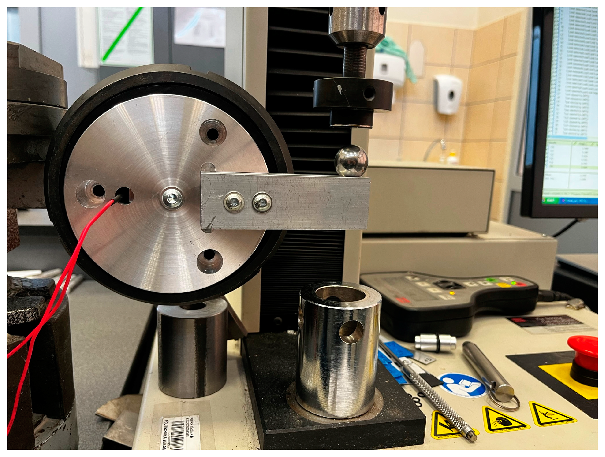
In order to verify the assumptions made, a test system was built that allows examining the performance of different types of brake pads. The MTS Insight testing machine and the experimental rig are shown in
Figure 11. The machine provided the force to rotate the device while measuring the displacement of the beam. The rotation of the device was monitored with an embedded encoder. This data correlated with displacement and provided information for braking torque plots. In addition, we were able to test the performance of an encoder while braking takes place.
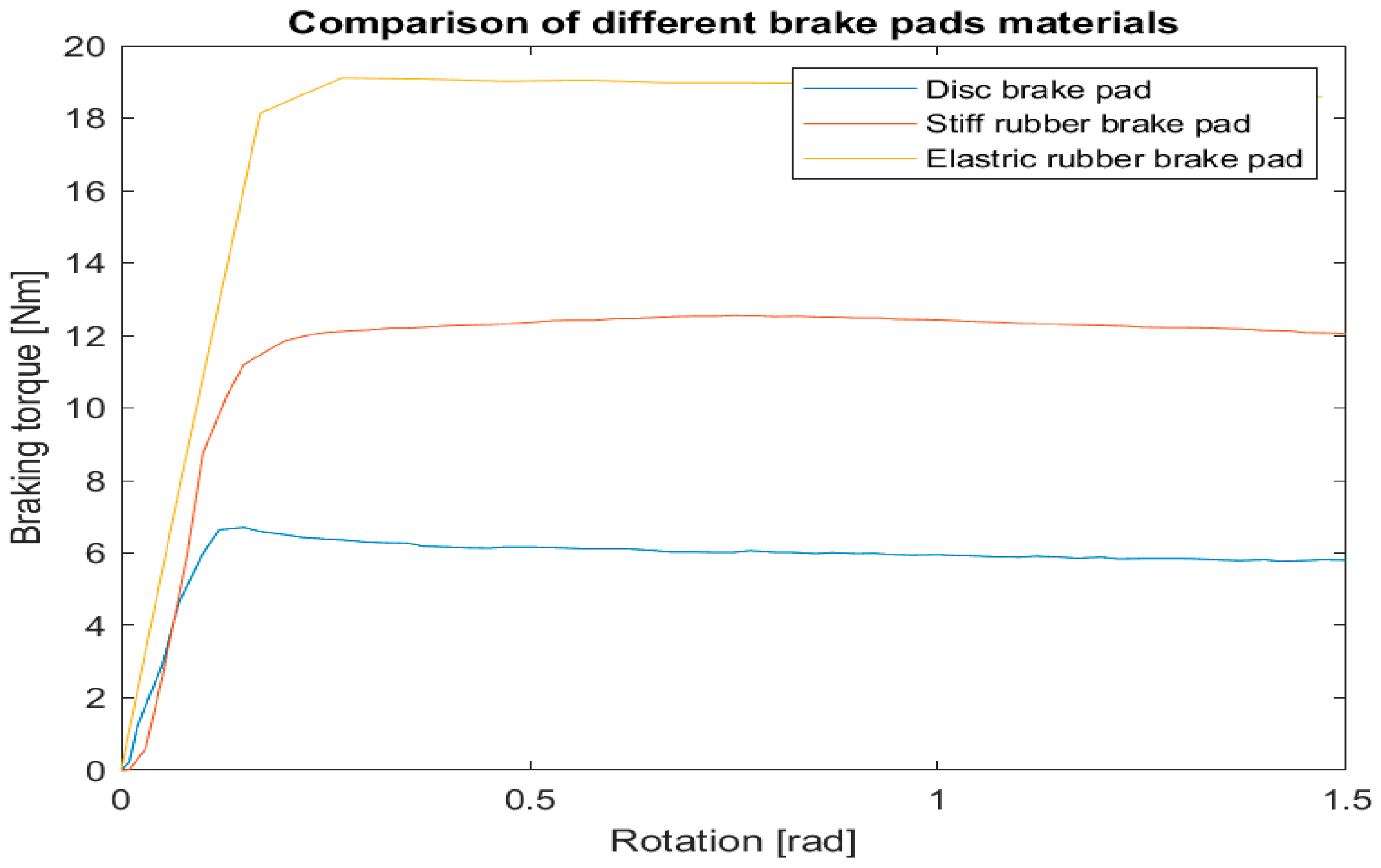
The braking torque measured using the experimental setup is plotted in
Figure 12 for three different materials as a function of the rotation angle. The best results were obtained using elastic rubber brake pads.
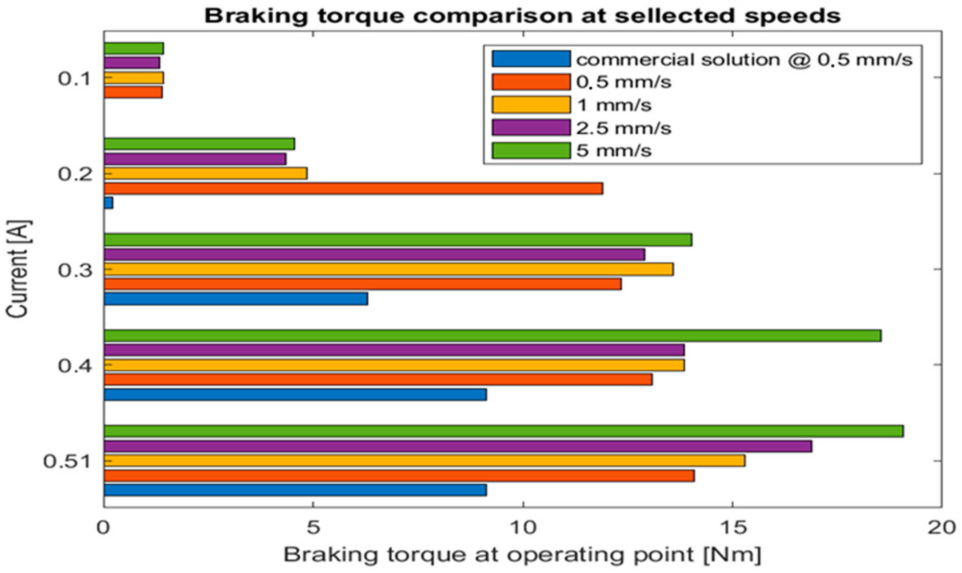
Further tests were performed for four braking speeds: 0.5 mm/s, 1 mm/s, 2.5 mm/s, and 5 mm/s. All tests were performed using the nominal voltage of an electromagnet—12 V with different current values in increments of 0.1 A. The results of the tests are depicted in
Figure 13. The results clearly show that our solution provided a smooth braking curve along the whole test range in contrast to a commercial one that has tended to have bursts of torque alternating with skidding phases.
Our test indicated that at the same current level, our solution provides twice as much braking torque in the operation point at a comparable speed. In addition, the torque increases with the speed of braking. This phenomenon is beneficial for the proposed use case as more dynamic movements might require more present force feedback that our device provides.
6. Summary
The designed joint presented here assures 19 Nm of braking torque. This value is sufficient for torques to be exerted by a limb’s action. Furthermore, respective contracting stimuli would be noticeable and provide valuable information for the operator through force feedback [
56,
57,
58].
Compared to the research of like solutions from the literature, our solution provides several advantages crucial for its use in a wearable haptic device. First, our device is small and relatively lightweight compared to eddy-current-based solutions. Our final prototype is 100 mm in diameter and 70 in height, weighing 765 g.
Gosline and Hayward [
37] reported that their device has 50 mm of effective disc radius (that would give as 100 mm in diameter), and this dimension does not include a toroidal electromagnet attached to the disk. The mass of the device was not mentioned, unfortunately. However, the authors mention using two re25 Maxon motors weighing 130 g each. We can assume that mass of both devices might be comparable. It is also difficult to directly compare braking torque due to using an integral of damping in their work. However, researchers achieved 4 mNms of damping, which is orders of magnitude away from our reported 19 Nm of torque.
A multipole solution based on Coulomb friction by Iqbal and Yi [
35] exhibited braking torque of 1 Nm at a current of 2.5 A. On the other hand, we achieved 19 Nm at only 0.51 A. Their second work [
36] is extremally interesting due to enabling damping movement on three axes with high torque of around 96.1 Nm about X-Y and 98 Nm around the Z-axis. However, those values were reached using 4 A of current. Since their report currents were indicated in increments of one, we can compare the non-energized state of 0 A (idle state) where reported torques are: about 4.3 Nm for X-Y and 4.9 Nm around Z-axis and for current of 1 A it was 15.9 Nm and 23 Nm respectively. Our solution is comparable to those solutions, although while idle (not energizged), our device provides free movement with no dumping.
It is also worth noting that our device is fully integrated with bearings, mounting points, and an encoder, ready to use in a haptic device without any modifications. Solutions of other researchers would require further work to implement them into complete haptic systems.
In addition, our design fits within the assumed constraints of mass and dimension. As a result, this device is slightly smaller than the commercial solution (diameter: 120 mm, height: 100 mm, mass: 770 g) while exhibiting higher braking performance.
A 19 Nm of braking torque value is comparable to the values achievable by commercial electromagnetic braking devices tested. It is also worth noting that the presented design is by far more cost-effective. Based on the market prices at the time of writing this paper, raw materials and components oscillate around USD 30 without an encoder. The price of a commercial product varies between USD 150 and 250 and still would require an implementation of an external encoder for integrating sensing and acting, fully integrated into the current design. We also observed the nominal operation of an encoder without any problems caused by braking action.
An additional advantage of the presented solution is its low power consumption. The power consumption of an integrated haptic joint is 12 W. Thermal energy generated by prolonged use of the electromagnet is well dispersed in the air because of using an all-aluminum housing.
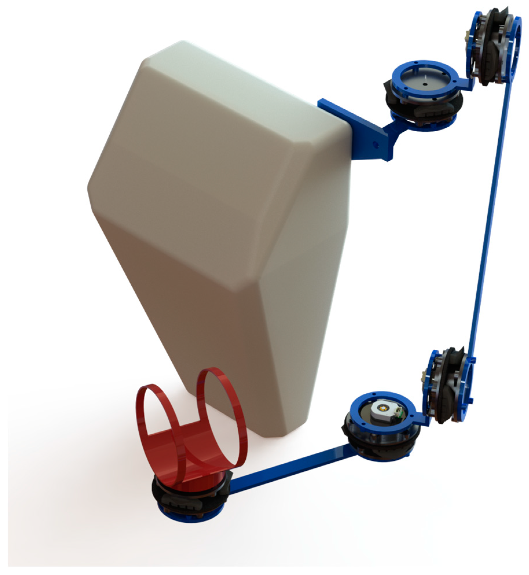
The current communication describes a research effort that is a part of a more ambitious plan to build an exoskeletal phantom device to control robotic arms. We do not explore the possibility of application of the system for rehabilitation needs as we do not see an only passive device suitable for this use case. It is the first in the series of project progress reports. The design of a complete phantom device is depicted in
Figure 14.
It consists of several links connected using integrated joints described in this paper. The kinematics of the solution does not directly follow the kinematic chain of a human arm. However, the presented device has the same range of movement and allows unrestricted operator motions. Furthermore, to give a broader range of information from the system, we use vibration motors on each link to inform the operator about approaching areas that are out of reach.
Author Contributions
M.R.: Software, Visualisation, Writing—Original Draft, Writing—Reviewing and Editing, Conceptualization, Investigation. K.D.: Methodology, Validation, Conceptualization, Resources, Investigation. R.G.: Software, Validation, Visualisation, Writing—Reviewing and Editing, Funding acquisition, Supervision. J.Ž.: Validation, Resources, Investigation. All authors have read and agreed to the published version of the manuscript.
Funding
The presented work was supported by the Ministry of Education and Science in Poland (research project No. WZ/WM-IIM/2/2022) and by the Polish National Agency for Academic Exchange as part of the Academic International Partnerships (PPI/APM/2018/1/00033/U/001 project).
Institutional Review Board Statement
Not applicable.
Informed Consent Statement
Not applicable.
Data Availability Statement
Not applicable.
Acknowledgments
Fruitful discussions with K. J. Kurzydlowski are kindly acknowledged. The authors note that Marcin Dziubek provided valuable support with conducting simulations.
Conflicts of Interest
The authors declare that they have no conflict of interest.
References
- Lee, C.-H.; Choi, J.; Lee, H.; Kim, J.; Lee, K.; Bang, Y. Exoskeletal Master Device for Dual Arm Robot Teaching. Mechatronics 2017, 43, 76–85. [Google Scholar] [CrossRef]
- Mallwitz, M.; Benitez, L.V.; Bongardt, B.; Will, N. The CAPIO Active Upper Body Exoskeleton. In Proceedings of the RoboAssist 2014—Wearable Robotics for Motion Assistance and Rehabilitation, IEEE, Hong Kong, China, 31 March 2014. [Google Scholar]
- All About Circuits Capio Exoskeleton—Robot System Controlling in Real Time. Available online: https://www.youtube.com/watch?v=cQhdtUMHi2M (accessed on 3 April 2022).
- German Research Center for Artificial Intelligence AILA/CAPIO Exoskeleton: German-Russian Cooporation for Remote Control of Robots. Available online: https://www.youtube.com/watch?v=5yOt8dylrTw (accessed on 3 April 2022).
- Engineering Haptic Devices; Hatzfeld, C.; Kern, T.A. (Eds.) Springer Series on Touch and Haptic Systems; Springer: London, UK, 2014; ISBN 978-1-4471-6517-0. [Google Scholar]
- Iwata, H. History of Haptic Interface. In Human Haptic Perception: Basics and Applications; Grunwald, M., Ed.; Birkhäuser: Basel, Switzerland, 2008; pp. 355–361. ISBN 978-3-7643-7612-3. [Google Scholar]
- Sears, A.; Jacko, J.A. (Eds.) The Human-Computer Interaction Handbook: Fundamentals, Evolving Technologies, and Emerging Applications, 2nd ed.; Human Factors and Ergonomics; Lawrence Erlbaum Associates: New York, NY, USA, 2008; ISBN 978-0-8058-5870-9. [Google Scholar]
- Phung, H.; Hoang, P.T.; Nguyen, C.T.; Dat Nguyen, T.; Jung, H.; Kim, U.; Choi, H.R. Interactive Haptic Display Based on Soft Actuator and Soft Sensor. In Proceedings of the 2017 IEEE/RSJ International Conference on Intelligent Robots and Systems (IROS), Vancouver, BC, Canada, 24–28 September 2017; pp. 886–891. [Google Scholar]
- Wang, D.; Guo, Y.; Liu, S.; Zhang, Y.; Xu, W.; Xiao, J. Haptic Display for Virtual Reality: Progress and Challenges. Virtual Real. Intell. Hardw. 2019, 1, 136–162. [Google Scholar] [CrossRef] [Green Version]
- Arata, J.; Kondo, H.; Ikedo, N.; Fujimoto, H. Haptic Device Using a Newly Developed Redundant Parallel Mechanism. IEEE Trans. Robot. 2011, 27, 201–214. [Google Scholar] [CrossRef]
- Yoon, J.; Ryu, J. Design, Fabrication, and Evaluation of a New Haptic Device Using a Parallel Mechanism. IEEE/ASME Trans. Mechatron. 2001, 6, 221–233. [Google Scholar] [CrossRef] [Green Version]
- Leonardis, D.; Gabardi, M.; Solazzi, M.; Frisoli, A. A Parallel Elastic Haptic Thimble for Wide Bandwidth Cutaneous Feedback. In Haptics: Science, Technology, Applications, Proceedings of the 12th International Conference, EuroHaptics 2020, Leiden, The Netherlands, 6–9 September 2020; Nisky, I., Hartcher-O’Brien, J., Wiertlewski, M., Smeets, J., Eds.; Springer International Publishing: Cham, Switzerland, 2020; pp. 389–397. [Google Scholar]
- Bouzit, M.; Burdea, G.; Popescu, G.; Boian, R. The Rutgers Master II-New Design Force-Feedback Glove. IEEE/ASME Trans. Mechatron. 2002, 7, 256–263. [Google Scholar] [CrossRef] [Green Version]
- Dos Anjos, G.A.; Santos, G.A.; Diaz Amado, J.A.; Soares Marques, J.E. Haptic Glove Development for Passive Control of a Robotic Arm. In Proceedings of the 2016 IEEE XXIII International Congress on Electronics, Electrical Engineering and Computing (INTERCON), Piura, Peru, 2–5 August 2016; pp. 1–6. [Google Scholar]
- Olabi, A.G.; Grunwald, A. Design and Application of Magneto-Rheological Fluid. Mater. Des. 2007, 28, 2658–2664. [Google Scholar] [CrossRef] [Green Version]
- Wang, J.; Meng, G. Magnetorheological Fluid Devices: Principles, Characteristics and Applications in Mechanical Engineering. Proc. Inst. Mech. Eng. Part L J. Mater. Des. Appl. 2001, 215, 165–174. [Google Scholar] [CrossRef]
- Bachman, P.; Milecki, A. MR Haptic Joystick in Control of Virtual Servo Drive. J. Phys. Conf. Ser. 2009, 149, 012034. [Google Scholar] [CrossRef]
- Liu, B.; Li, W.H.; Kosasih, P.B.; Zhang, X.Z. Development of an MR-Brake-Based Haptic Device. Smart Mater. Struct. 2006, 15, 1960–1966. [Google Scholar] [CrossRef]
- Agharese, N.; Cloyd, T.; Blumenschein, L.H.; Raitor, M.; Hawkes, E.W.; Culbertson, H.; Okamura, A.M. HapWRAP: Soft Growing Wearable Haptic Device. In Proceedings of the 2018 IEEE International Conference on Robotics and Automation (ICRA), Brisbane, Australia, 21–25 May 2018; pp. 5466–5472. [Google Scholar]
- Kodama, T.; Izumi, S.; Masaki, K.; Kawaguchi, H.; Maenaka, K.; Yoshimoto, M. Large Displacement Haptic Stimulus Actuator Using Piezoelectric Pump for Wearable Devices. In Proceedings of the 2015 37th Annual International Conference of the IEEE Engineering in Medicine and Biology Society (EMBC), Milan, Italy, 25–29 August 2015; pp. 1172–1175. [Google Scholar]
- Wang, H.; Cheng, X.; Huang, P.; Yu, M.; Ma, J.; Peng, S.; Cheng, Y.; Yu, Y.; Yang, W.; Wang, P.; et al. A Soft Electro-Hydraulic Pneumatic Actuator with Self-Sensing Capability toward Multi-Modal Haptic Feedback. Actuators 2022, 11, 74. [Google Scholar] [CrossRef]
- Gosselin, F.; Ferlay, F.; Janot, A. Development of a New Backdrivable Actuator for Haptic Interfaces and Collaborative Robots. Actuators 2016, 5, 17. [Google Scholar] [CrossRef] [Green Version]
- Suzuki, T.; Magatani, K. Development of the Haptic Device Using Linear Oscillatory Actuators for the Disabled. IJBBB 2016, 6, 99–104. [Google Scholar] [CrossRef] [Green Version]
- Kato, M.; Kono, Y.; Yasukawa, M.; Hirata, K.; Niguchi, N. Power-Saving Method of Linear Oscillatory Actuator for Mobile Haptic Device Using Mechanical Resonance. J. Jpn. Soc. Appl. Electromagn. Mech. 2019, 27, 31–36. [Google Scholar] [CrossRef] [Green Version]
- Kwon, D.-S.; Yang, T.-H.; Cho, J. Trend Amp; Prospects of Haptic Technology in Mobile Devices. In Proceedings of the 2010 IEEE International Symposium on Industrial Electronics, Bari, Italy, 4–7 July 2010; pp. 3778–3783. [Google Scholar]
- Texas Instruments Incorporated DRV2605L 2-To5.2-V Haptic Driver for LRA and ERM with Effect Library and Smart-Loop Architecture. Available online: https://www.ti.com/lit/ds/symlink/drv2605l.pdf?ts=1650965805367&ref_url=https%253A%252F%252Fwww.google.com%252F (accessed on 27 April 2022).
- Dialog Semiconductor DA7280 LRA/ERM Haptic Driver with Multiple Input Triggers, Integrated Waveform Memory and Wideband Support. Available online: https://cdn.sparkfun.com/assets/a/e/d/1/9/da7280_datasheet_3v0.pdf (accessed on 27 April 2022).
- Bozic, M.; Todorović, D.; Petković, M.; Zerbe, V.; Đorđević, G.S. Advanced DC Motor Drive for Haptic Devices. Electronics 2012, 16, 100–103. [Google Scholar] [CrossRef] [Green Version]
- Duy Le, K.; Nguyen, H.D.; Ranthumugala, D.; Forrest, A. Haptic Driving System for Surge Motion Control of Underwater Remotely Operated Vehicles. In Proceedings of the 2014 International Conference on Modelling, Identification Control, Melbourne, VIC, Australia, 3–5 December 2014; pp. 207–212. [Google Scholar]
- Mehling, J.S.; Colgate, J.E.; Peshkin, M.A. Increasing the Impedance Range of a Haptic Display by Adding Electrical Damping. In Proceedings of the First Joint Eurohaptics Conference and Symposium on Haptic Interfaces for Virtual Environment and Teleoperator Systems, World Haptics Conference, Pisa, Italy, 18–20 March 2005; pp. 257–262. [Google Scholar]
- Millet, G.; Haliyo, S.; Regnier, S.; Hayward, V. The Ultimate Haptic Device: First Step. In Proceedings of the World Haptics 2009—Third Joint EuroHaptics conference and Symposium on Haptic Interfaces for Virtual Environment and Teleoperator Systems, Salt Lake City, UT, USA, 18–20 March 2009; pp. 273–278. [Google Scholar]
- Nagai, S.; Nozaki, T.; Kawamura, A. Real-Time Position Sensorless Estimation of Position and Force of Solenoid Actuator for Haptic Devices. In Proceedings of the 2015 17th European Conference on Power Electronics and Applications (EPE’15 ECCE-Europe), Geneva, Switzerland, 8–10 September 2015; pp. 1–9. [Google Scholar]
- Savioz, G.; Perriard, Y. Towards Self-Sensed Drives in Linear Haptic Systems. In Proceedings of the 2009 International Conference on Electrical Machines and Systems, Tokyo, Japan, 15–18 November 2009; pp. 1–5. [Google Scholar]
- Lesobre, A.; Ahmedl, A.H.B.; Drecq, D. An Analytical Dynamic Model of Eddy-Current Brakes. In Proceedings of the IEMDC 2001. IEEE International Electric Machines and Drives Conference (Cat. No.01EX485), Cambridge, MA, USA, 17–20 June 2001; pp. 122–125. [Google Scholar]
- Iqbal, H.; Yi, B.-J. Design of a New Bilayer Multipole Electromagnetic Brake System for a Haptic Interface. Appl. Sci. 2019, 9, 5394. [Google Scholar] [CrossRef] [Green Version]
- Iqbal, H.; Yi, B.-J. Design and Experimental Verification of a 3-DOF Spherical Electromagnetic Brake for Haptic Interface. Int. J. Control Autom. Syst. 2020, 18, 1299–1309. [Google Scholar] [CrossRef]
- Gosline, A.H.C.; Hayward, V. Eddy Current Brakes for Haptic Interfaces: Design, Identification, and Control. IEEE/ASME Trans. Mechatron. 2008, 13, 669–677. [Google Scholar] [CrossRef] [Green Version]
- Ge, X.; Peng, S.-K.; Wang, B.; Shapiro, J.; Gillespie, B.; Salisbury, C. A High Bandwidth Low Inertia Motor for Haptic Rendering Based on Clutched Eddy Current Effects. In Proceedings of the 2012 IEEE Haptics Symposium (HAPTICS), Vancouver, BC, Canada, 4–7 March 2012; pp. 83–89. [Google Scholar]
- Campion, G.; Gosline, A.H.; Hayward, V. Initial Results Using Eddy Current Brakes as Fast Turn-on, Programmable Physical Dampers for Haptic Rendering. In Proceedings of the 2006 14th Symposium on Haptic Interfaces for Virtual Environment and Teleoperator Systems, Alexandria, VA, USA, 25–26 March 2006; pp. 73–74. [Google Scholar]
- Goodrich, M.A.; Schultz, A.C. Human-Robot Interaction: A Survey. Found. Trends Hum.-Comput. Interact. 2007, 1, 203–275. [Google Scholar] [CrossRef]
- ROBOTIS ROBOTIS E-Manual MX-64T/R/AT/AR. Available online: https://emanual.robotis.com/docs/en/dxl/mx/mx-64/ (accessed on 27 April 2022).
- Conti, F.; Khatib, O. A New Actuation Approach for Haptic Interface Design. Int. J. Robot. Res. 2009, 28, 834–848. [Google Scholar] [CrossRef]
- Kamieński, K.; Rećko, M.; Dzierżek, K. Design of a Phantom Device with a Safety System Based on a Non-Invasive Method of Monitoring Blood Flow within an Operator’s Arm. In Proceedings of the 2021 25th International Conference on Methods and Models in Automation and Robotics (MMAR), Międzyzdroje, Poland, 23–26 August 2021; pp. 85–90. [Google Scholar]
- Dziubek, M.; Falkowski, M.; Łapińska, P.; Grądzki, R. Research of Hybrid Magnetic System Used in Autonomous MegaSumo Robots. IJMERR 2021, 10, 343–348. [Google Scholar] [CrossRef]
- Jones, D.S.; Sneddon, I.N.; Ulam, S.; Stark, M. The Theory of Electromagnetism; Elsevier Science: Kent, UK, 2014; ISBN 978-1-4832-7904-6. [Google Scholar]
- Cheng, D.K. Field and Wave Electromagnetics; Addison-Wesley: Boston, MA, USA, 1989; ISBN 978-0-201-52820-6. [Google Scholar]
- Mallinson, J. One-Sided Fluxes—A Magnetic Curiosity? IEEE Trans. Magn. 1973, 9, 678–682. [Google Scholar] [CrossRef] [Green Version]
- Tipler, P.A.; Mosca, G. Physics for Scientists and Engineers; W. H. Freeman: New York, NY, USA, 2004; ISBN 978-0-7167-8339-8. [Google Scholar]
- Purcell, E.M. Electricity and Magnetism, 3rd ed.; Cambridge University Press: Cambridge, UK, 2013; ISBN 978-1-107-01402-2. [Google Scholar]
- Engineering ToolBox Friction—Friction Coefficients and Calculator. Available online: https://www.engineeringtoolbox.com/friction-coefficients-d_778.html (accessed on 27 April 2022).
- Coefficient of Friction|Engineering Library. Available online: https://engineeringlibrary.org/reference/coefficient-of-friction (accessed on 11 October 2022).
- Friction Coefficients—Alloys and Metals. Available online: https://structx.com/Material_Properties_005a.html (accessed on 11 October 2022).
- Coefficients of Friction. Available online: https://www.roymech.co.uk/Useful_Tables/Tribology/co_of_frict.htm (accessed on 11 October 2022).
- Marks, L.S. Marks’ Standard Handbook for Mechanical Engineers, 11th ed.; Avallone, E.A., Baumeister, T., Sadegh, A.M., Eds.; McGraw-Hill: New York, NY, USA, 2007; ISBN 978-0-07-142867-5. [Google Scholar]
- Budynas, R.G.; Nisbett, J.K.; Shigley, J.E. Shigley’s Mechanical Engineering Design, 11th ed.; McGraw-Hill Education: New York, NY, USA, 2020; ISBN 978-0-07-339821-1. [Google Scholar]
- Hollerbach, J.M.; Flash, T. Dynamic Interactions between Limb Segments during Planar Arm Movement. Biol. Cybern. 1982, 44, 67–77. [Google Scholar] [CrossRef] [PubMed]
- Nagarsheth, H.J.; Savsani, P.V.; Patel, M.A. Modeling and Dynamics of Human Arm. In Proceedings of the 2008 IEEE International Conference on Automation Science and Engineering, Arlington, VA, USA, 23–26 August 2008; pp. 924–928. [Google Scholar]
- Rosen, J.; Perry, J.C.; Manning, N.; Burns, S.; Hannaford, B. The Human Arm Kinematics and Dynamics during Daily Activities—Toward a 7 DOF Upper Limb Powered Exoskeleton. In Proceedings of the 12th International Conference on Advanced Robotics, ICAR ’05, Seattle, WA, USA, 18–20 July 2005; pp. 532–539. [Google Scholar]
Figure 1.
Measurement mesh.
Figure 1.
Measurement mesh.
Figure 2.
Surface magnetic flux density.
Figure 2.
Surface magnetic flux density.
Figure 3.
3D view of the magnetic flux density.
Figure 3.
3D view of the magnetic flux density.
Figure 4.
Force of attraction between steel plate and one electromagnet.
Figure 4.
Force of attraction between steel plate and one electromagnet.
Figure 5.
Cross-section of the measurement mesh during simulation.
Figure 5.
Cross-section of the measurement mesh during simulation.
Figure 6.
Cross-section view of magnetic flux density during simulation of two magnets.
Figure 6.
Cross-section view of magnetic flux density during simulation of two magnets.
Figure 7.
3D view of the magnetic flux density distribution in a simulation of two magnets.
Figure 7.
3D view of the magnetic flux density distribution in a simulation of two magnets.
Figure 8.
Results of two magnet simulation.
Figure 8.
Results of two magnet simulation.
Figure 9.
Integrated joint (CAD visualization and real-life device).
Figure 9.
Integrated joint (CAD visualization and real-life device).
Figure 10.
Cross-section of an integrated joint. 1—encoder, 2—steel plate, 3—electromagnet, 4—ball bearing housing, 5—brake disc, 6—brake pad, 7—electromagnet housing.
Figure 10.
Cross-section of an integrated joint. 1—encoder, 2—steel plate, 3—electromagnet, 4—ball bearing housing, 5—brake disc, 6—brake pad, 7—electromagnet housing.
Figure 12.
Comparison chart of braking torque of the tested brake pads materials—5 mm/s.
Figure 12.
Comparison chart of braking torque of the tested brake pads materials—5 mm/s.
Figure 13.
Braking solutions comparison (our design vs. commercial) of braking torque at different operating speeds in a point of operation regarding chosen current levels supplied to the electromagnet.
Figure 13.
Braking solutions comparison (our design vs. commercial) of braking torque at different operating speeds in a point of operation regarding chosen current levels supplied to the electromagnet.
Figure 14.
The proposed phantom device.
Figure 14.
The proposed phantom device.
Table 1.
Electromagnet characteristic.
Table 1.
Electromagnet characteristic.
| Parameter | Value [Unit] |
|---|
| Manufacturer’s description/model | LS-P50/30 |
| Diameter | φ 50 [mm] |
| Height | 30 [mm] |
| Weight | 319 [g] |
| Voltage | 12 [V] DC |
| Power consumption | 11 [W] |
| Coil resistance | 30.372 [Ω] |
| Coil inductance | 0.86905 [H] |
| Coil current [used during simulation] | 0.6 [A] |
| The rated force of attraction | 60 [kg] |
Table 2.
Simulation parameters.
Table 2.
Simulation parameters.
| Parameter | Value [Unit] |
|---|
| Parameter | 750 |
| Relative permeability of structural steel (steel plate) | 400 |
| Relative permeability of soft iron (casing and core of the electromagnet) | 700 |
| Number of coils | 0.26 [mm] |
| Wire diameter | 0.1 [mm] |
| Default distance between objects | 750 |
Table 3.
Mesh properties.
Table 3.
Mesh properties.
| Mesh Property | Value [Unit] |
|---|
| Geometric entity level | Entire geometry |
| Element’s quality measure | Skewness |
| Mesh vertices | 37,296 |
| Element type | Triangle |
| Number of triangles | 74,411 |
| Edge elements | 3853 |
| Vertex elements | 16 |
| Minimum element quality | 0.0796 |
| Average element quality | 0.8602 |
| Element area ratio | 4.59 × 10⁻⁷ |
| Mesh area | 10,050 [mm2] |
Table 4.
Mesh properties during simulation of two electromagnets.
Table 4.
Mesh properties during simulation of two electromagnets.
| Mesh Property | Value [Unit] |
|---|
| Geometric entity level | Entire geometry |
| Element’s quality measure | Skewness |
| Mesh vertices | 3192 |
| Element type | Triangle |
| Number of triangles | 6282 |
| Minimum element quality | 0.5266 |
| Average element quality | 0.8435 |
| Element area ratio | 1.774 × 10⁻⁴ |
| Mesh area | 10,040 [mm22] |
| Publisher’s Note: MDPI stays neutral with regard to jurisdictional claims in published maps and institutional affiliations. |
© 2022 by the authors. Licensee MDPI, Basel, Switzerland. This article is an open access article distributed under the terms and conditions of the Creative Commons Attribution (CC BY) license (https://creativecommons.org/licenses/by/4.0/).


