
Monopole Antenna with Enhanced Bandwidth and Stable Radiation Patterns Using Metasurface and Cross-Ground Structure


Abstract
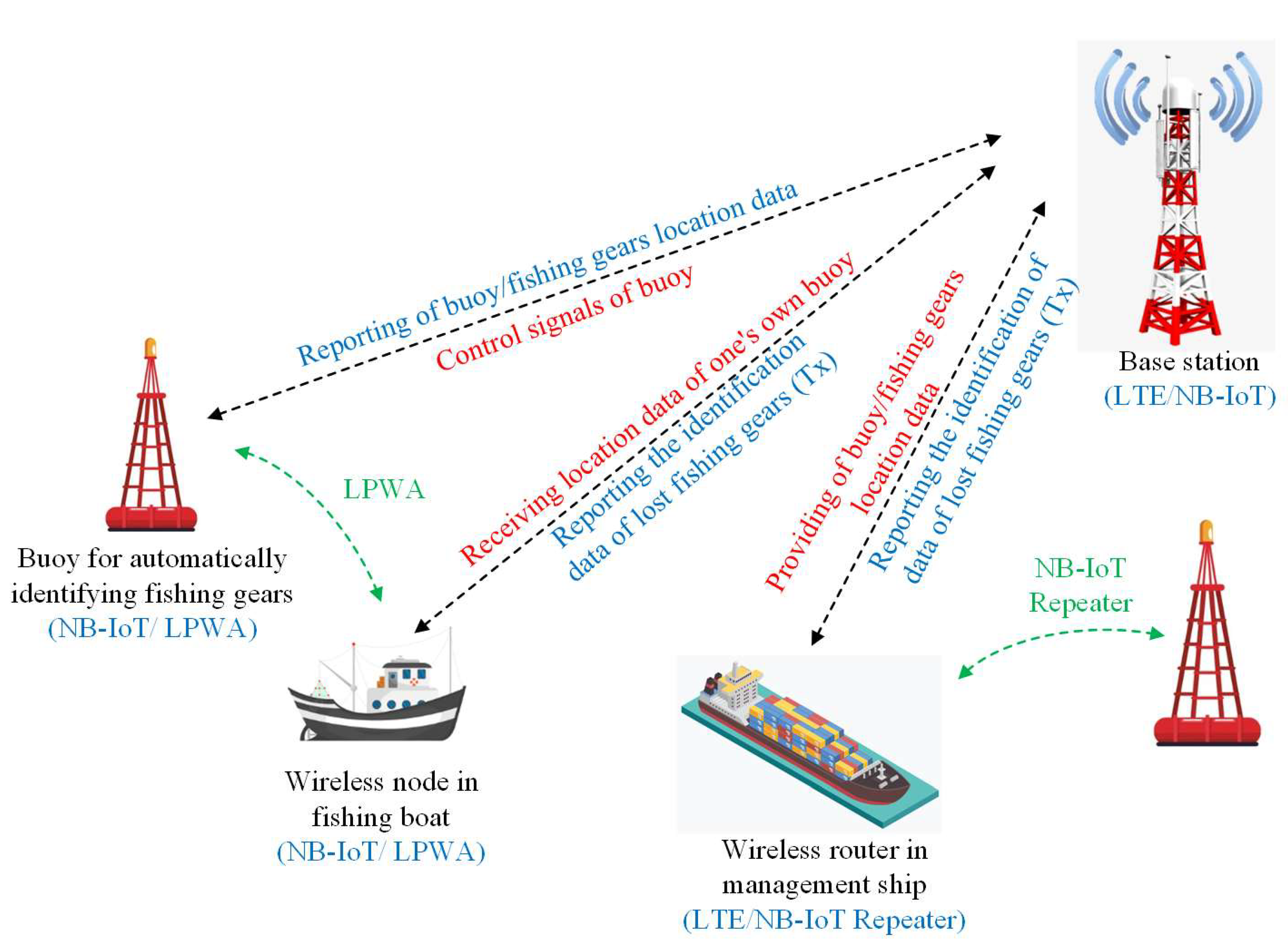
:1. Introduction
2. Antenna Geometry and Configuration
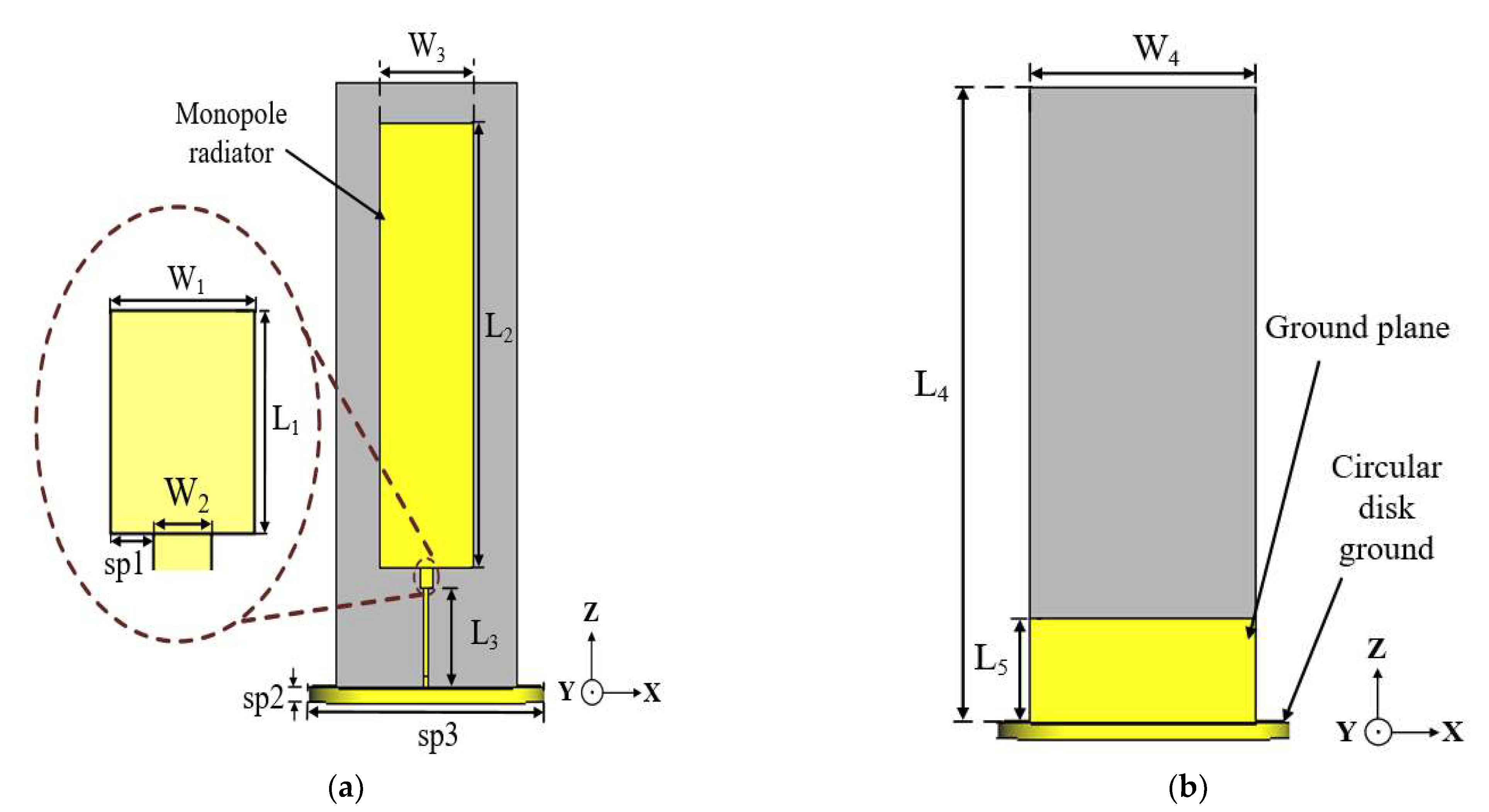
2.1. Conventional Monopole Antenna
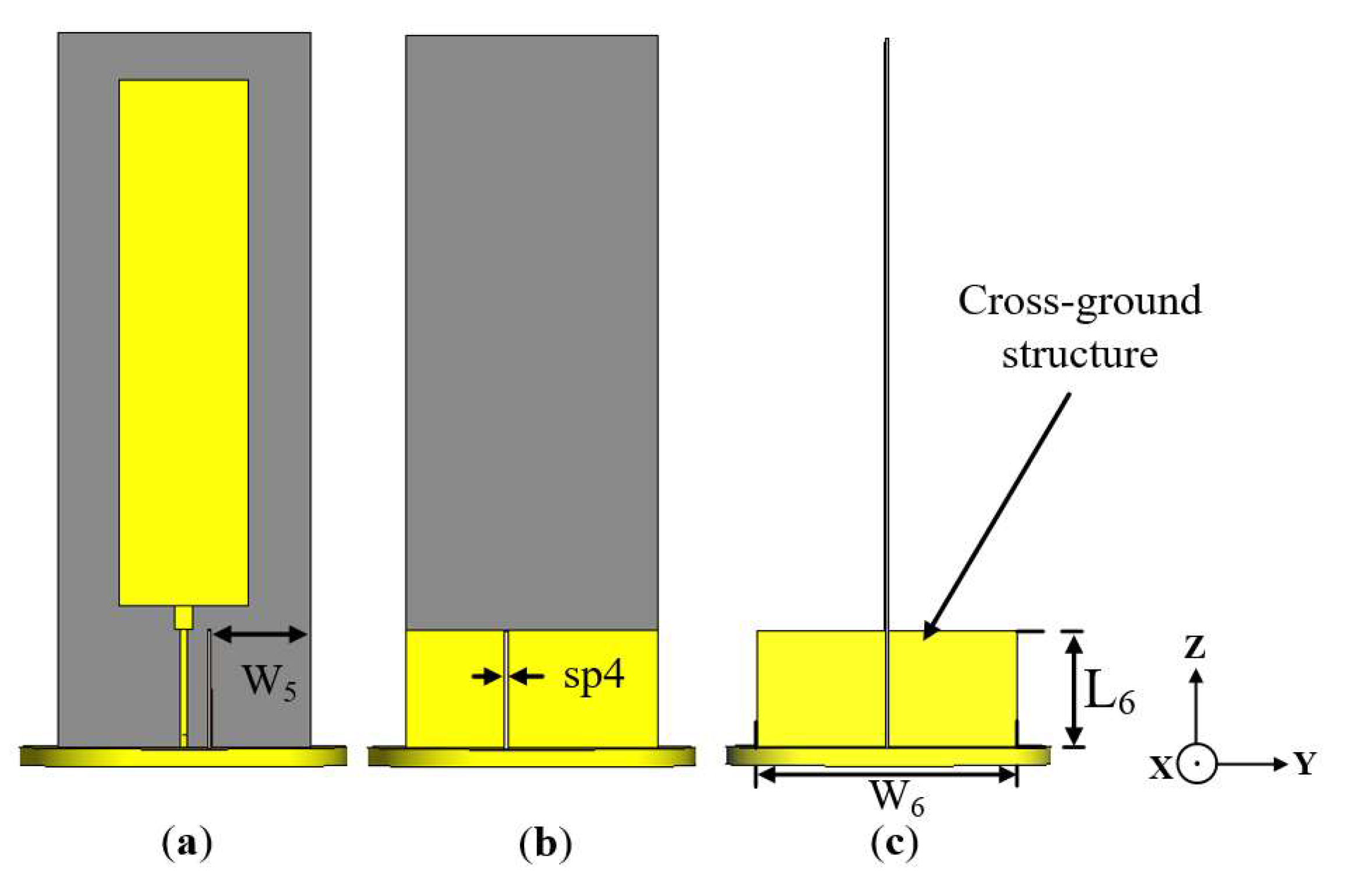
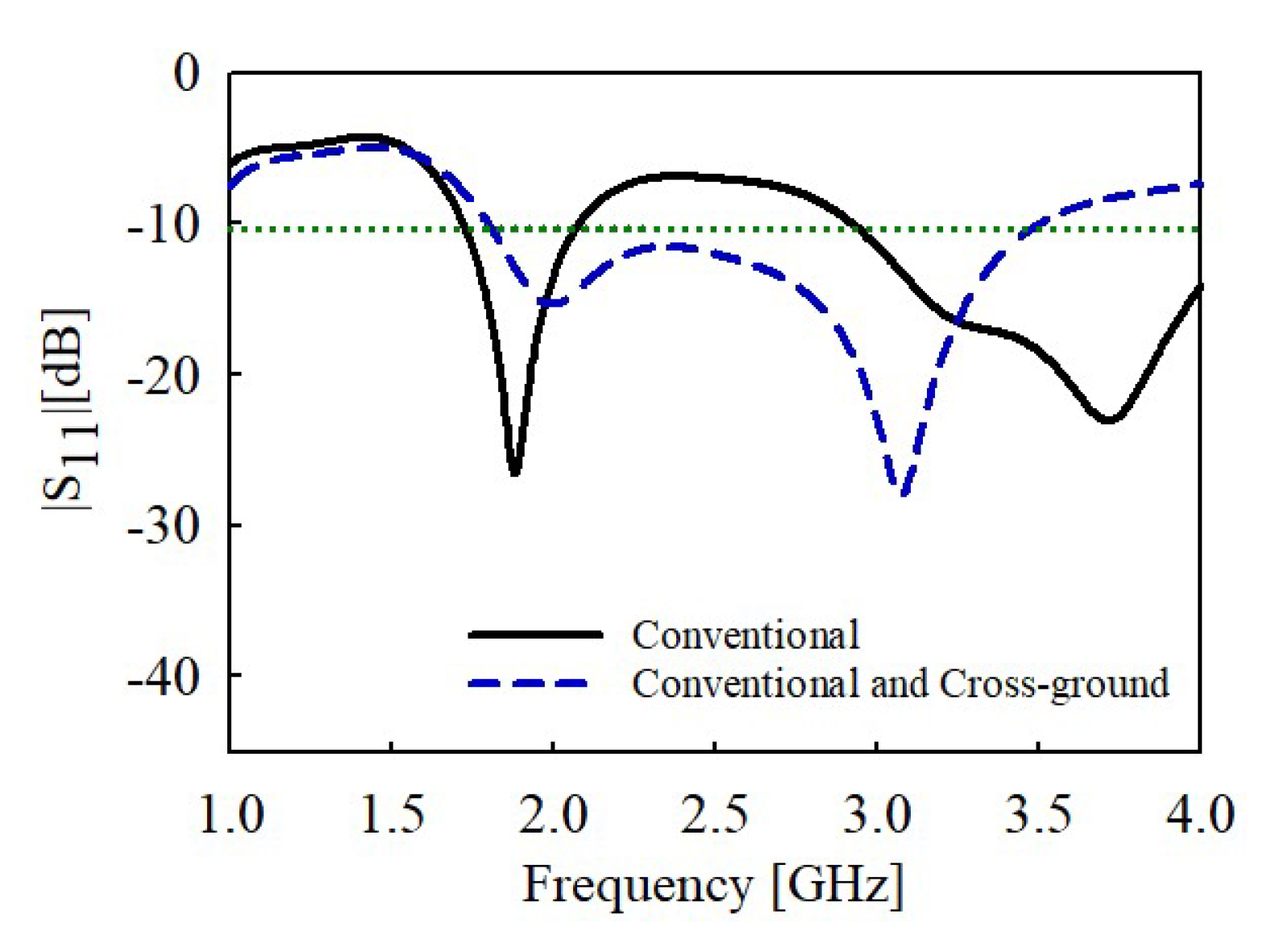
2.2. Conventional Antenna Incorporated with Cross-Ground
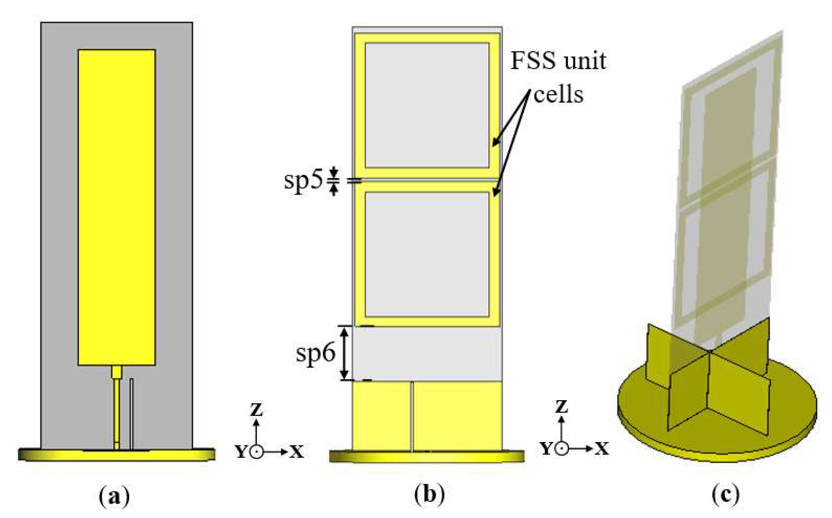
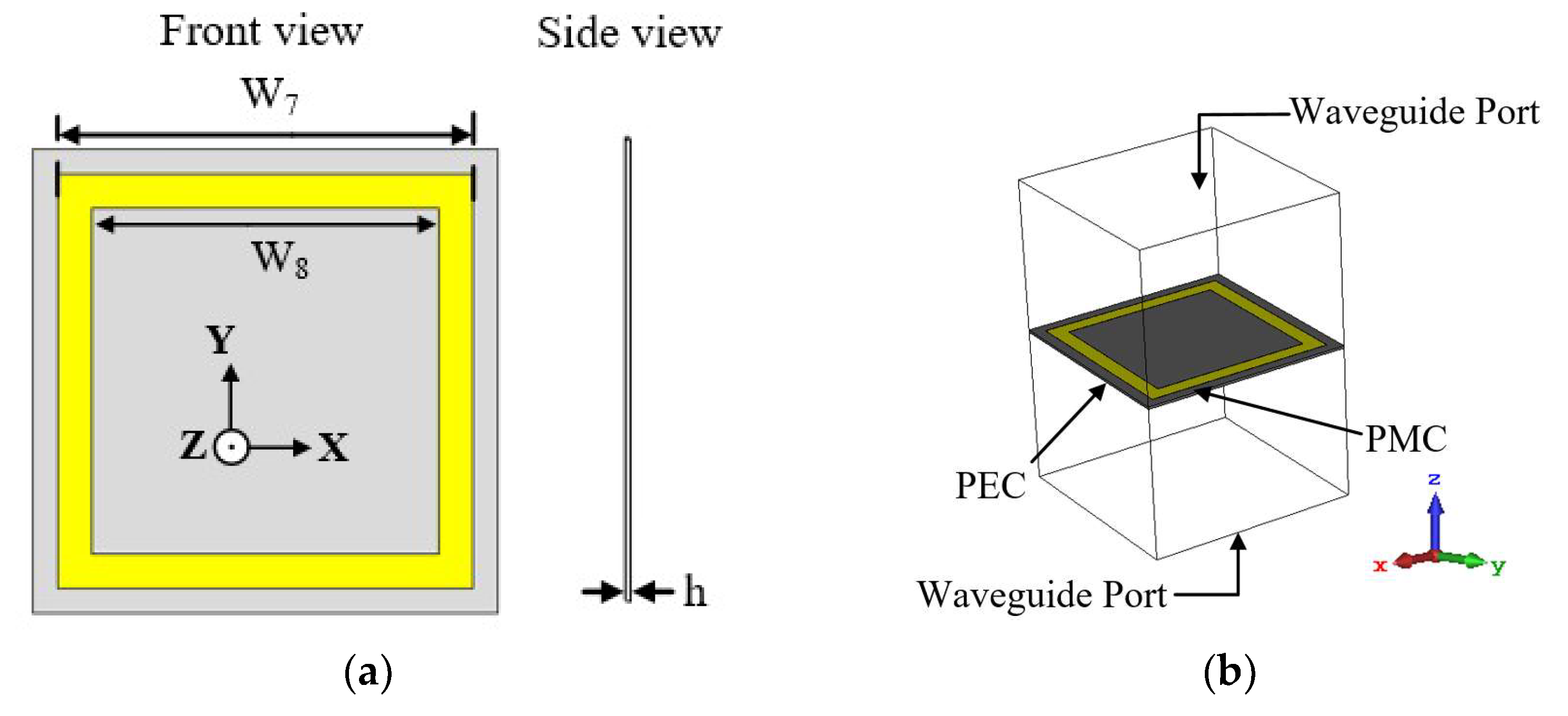
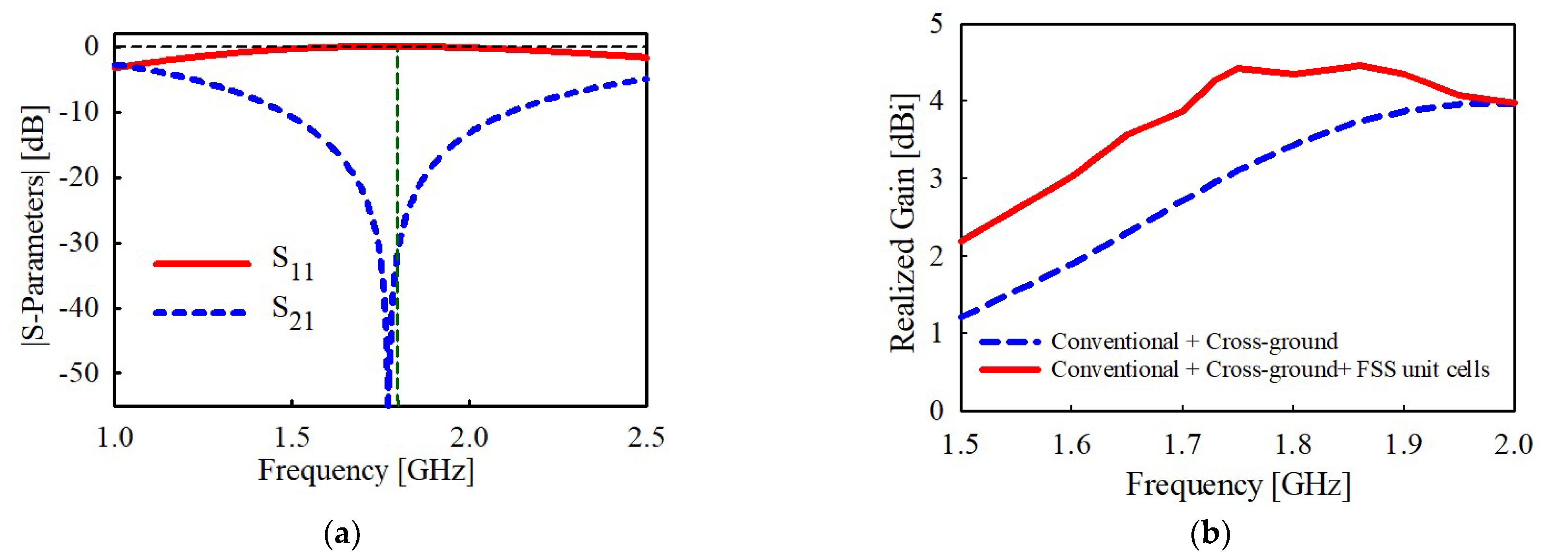
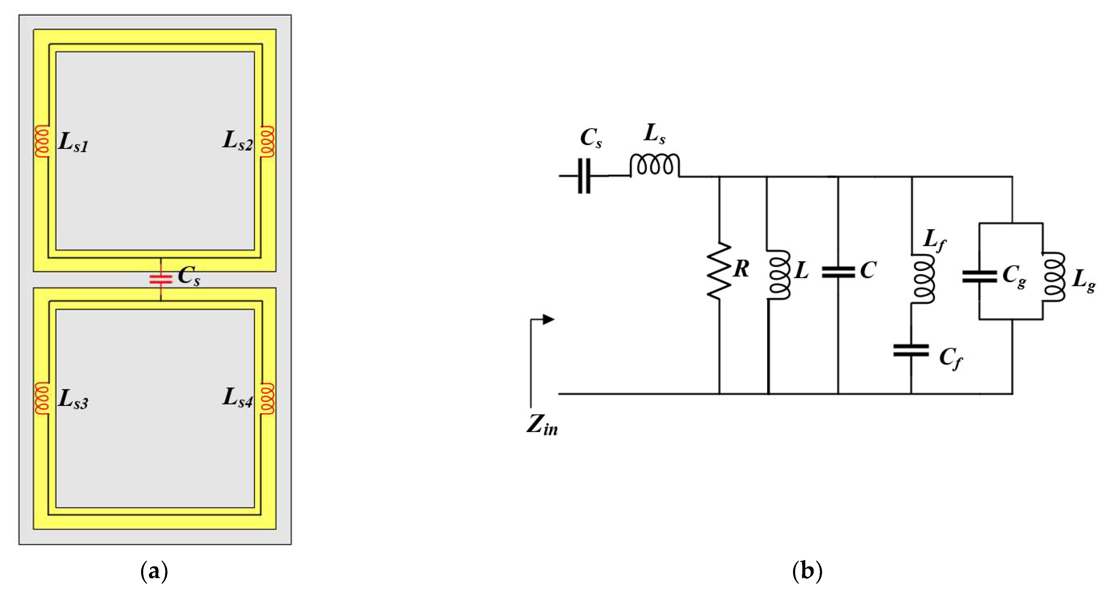
2.3. Monopole Antenna Incorporated with Both Cross-Ground Structure and FSS Unit Cells
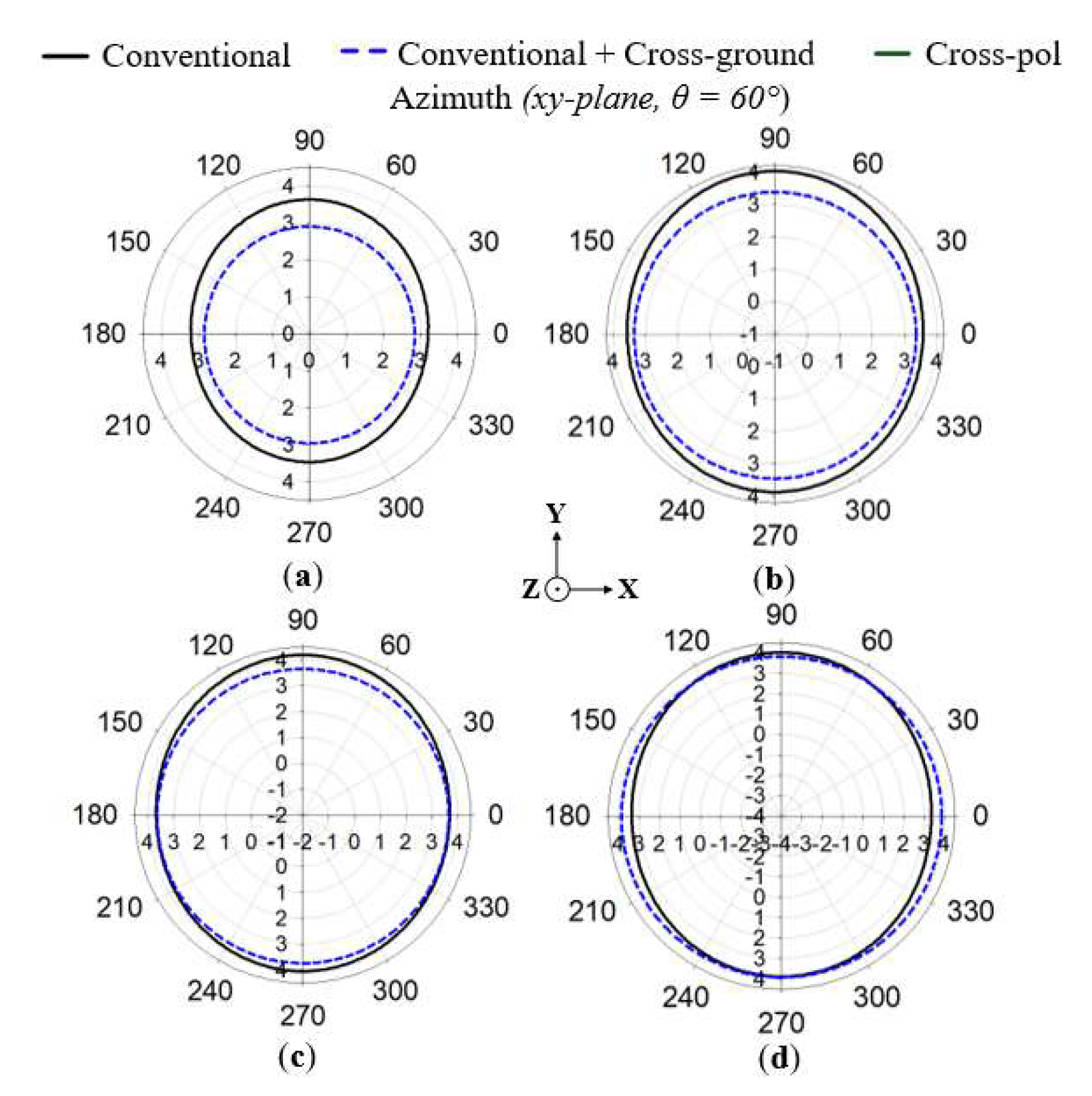
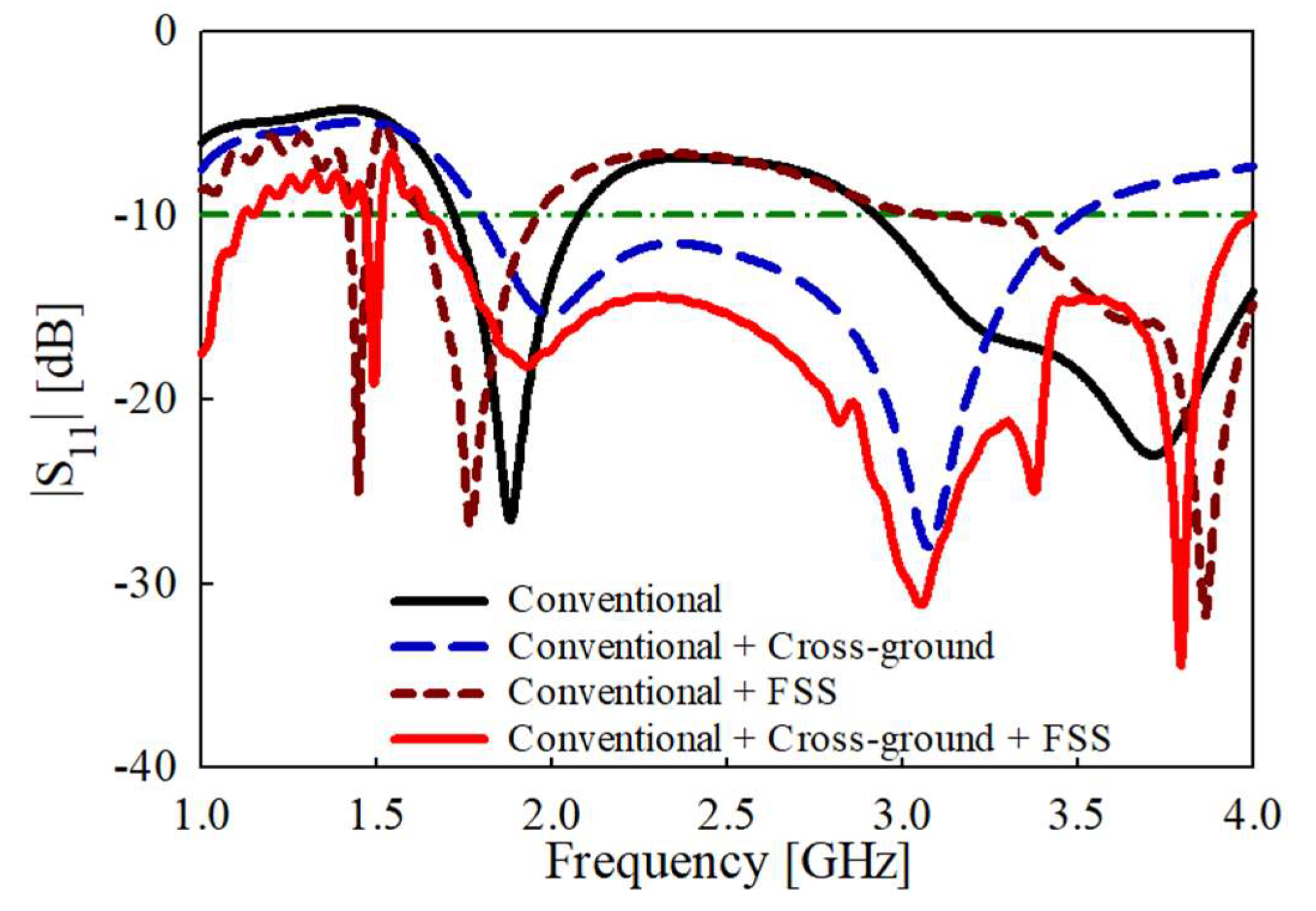
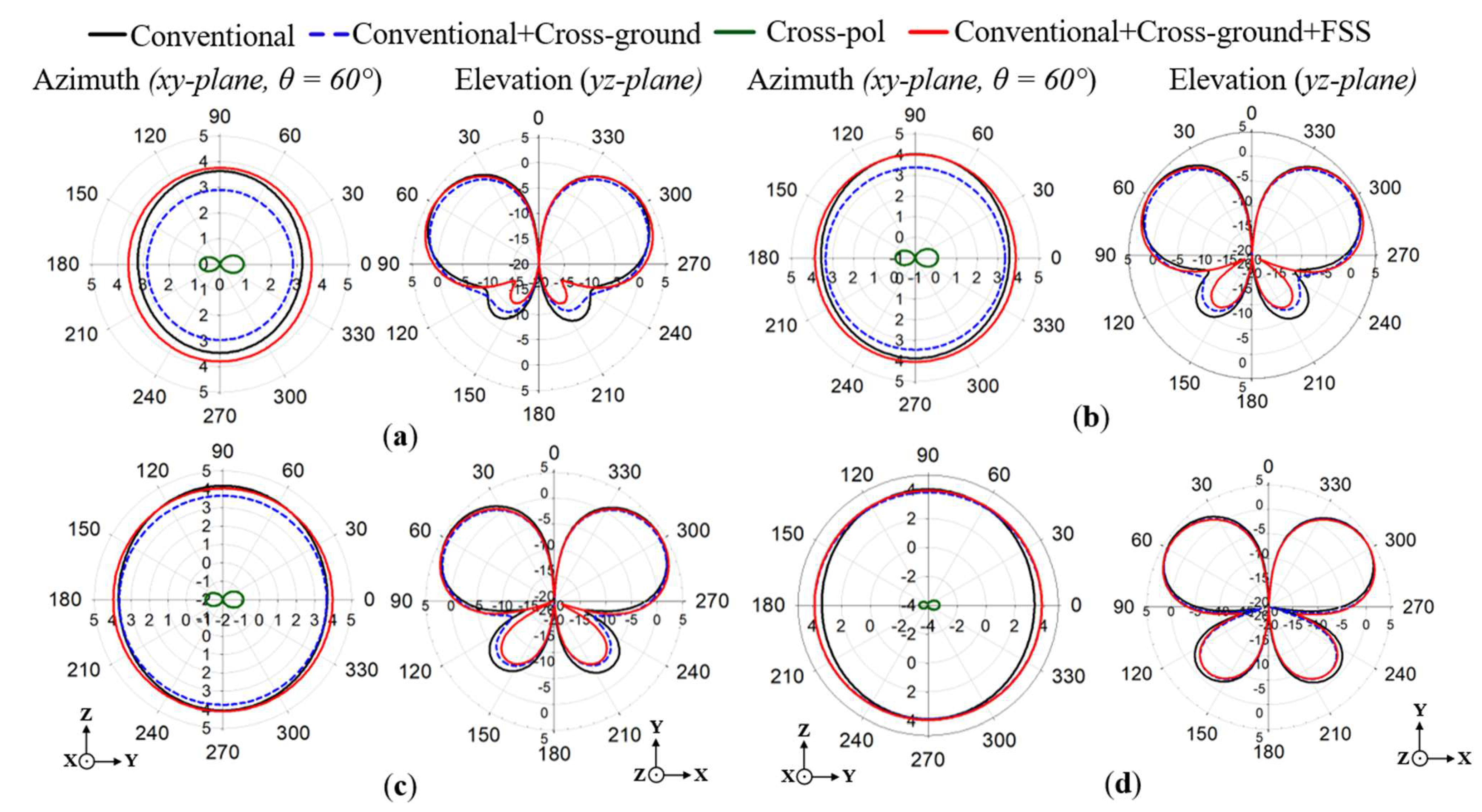
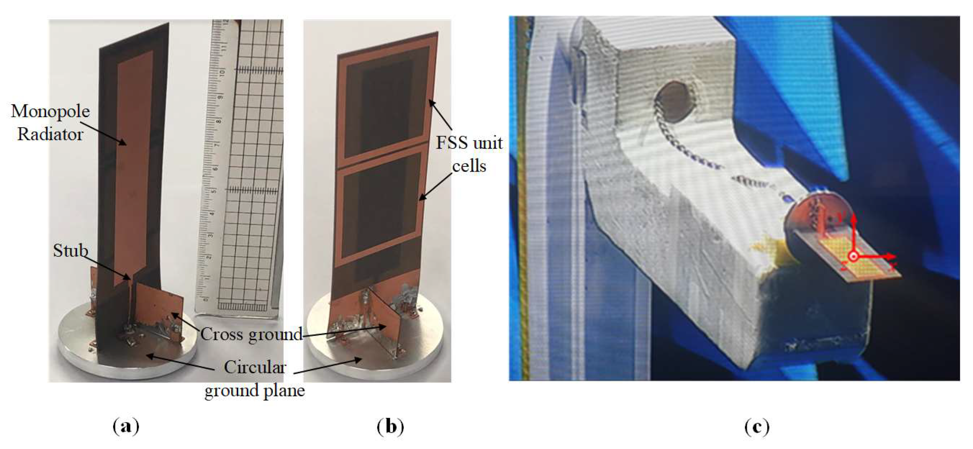
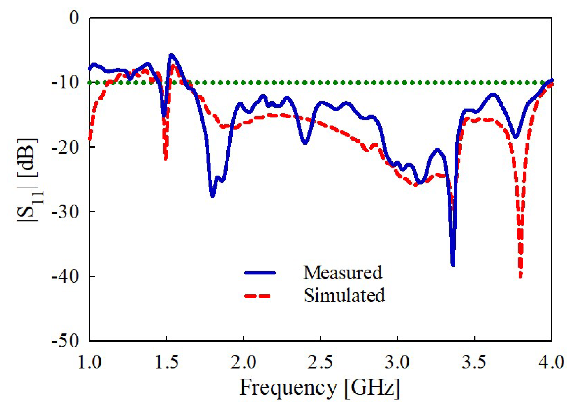
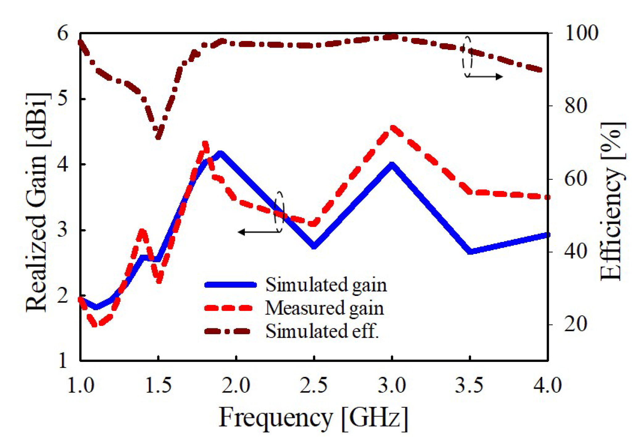
3. Measurement Results and Discussion
4. Conclusions
Author Contributions
Funding
Institutional Review Board Statement
Informed Consent Statement
Data Availability Statement
Conflicts of Interest
References
- Wu, C.; Lai, C.-F. A Survey on Improving the Wireless Communication with Adaptive Antenna Selection by Intelligent Method. Comput. Commun. 2022, 181, 374–403. [Google Scholar] [CrossRef]
- Manavalan, E.; Jayakrishna, K. A Review of Internet of Things (IoT) Embedded Sustainable Supply Chain for Industry 4.0 Requirements. Comput. Ind. Eng. 2019, 127, 925–953. [Google Scholar] [CrossRef]
- Routray, S.K.; Sharmila, K.P.; Javali, A.; Ghosh, A.D.; Sarangi, S. An Outlook of Narrowband IoT for Industry 4.0. In Proceedings of the 2020 Second International Conference on Inventive Research in Computing Applications (ICIRCA), Coimbatore, India, 15–17 July 2020; IEEE: Piscataway, NJ, USA, 2020; pp. 923–926. [Google Scholar]
- Pattnaik, S.K.; Samal, S.R.; Bandopadhaya, S.; Swain, K.; Choudhury, S.; Das, J.K.; Mihovska, A.; Poulkov, V. Future Wireless Communication Technology towards 6G IoT: An Application-Based Analysis of IoT in Real-Time Location Monitoring of Employees inside Underground Mines by Using BLE. Sensors 2022, 22, 3438. [Google Scholar] [CrossRef] [PubMed]
- Majid, M.; Habib, S.; Javed, A.R.; Rizwan, M.; Srivastava, G.; Gadekallu, T.R.; Lin, J.C.-W. Applications of Wireless Sensor Networks and Internet of Things Frameworks in the Industry Revolution 4.0: A Systematic Literature Review. Sensors 2022, 22, 2087. [Google Scholar] [CrossRef]
- Al-Janabi, M.A.; Kayhan, S.K. Reconfigurable broadband printed monopole antenna for portable smart IoT applications. Int. J. Commun. Syst. 2021, 34, 5. [Google Scholar] [CrossRef]
- Lizzi, L.; Ferrero, F.; Monin, P.; Danchesi, C.; Boudaud, S. Design of Miniature Antennas for IoT Applications. In Proceedings of the 2016 IEEE Sixth International Conference on Communications and Electronics (ICCE), Ha-Long, Vietnam, 27–29 July 2016; IEEE: Piscataway, NJ, USA, 2016; pp. 234–237. [Google Scholar]
- Chung, M.-A.; Yang, C.-W. A miniaturized planar monopole antenna based on a coupling structure for compact mobile Internet of Things (IoT) and electric vehicles (EVs) device applications in 5G, LTE, WLAN, WiMAX, Sirius/XM Radio, V2X, and DSRC wireless systems. Int. J. Antennas Propag. 2021, 2021, 7535382. [Google Scholar] [CrossRef]
- Choi, H.-D.; Lee, S.-R. PCB pattern antenna of 920 MHz band for marine IoT services. J. Adv. Navig. Technol. 2019, 23, 430–436. [Google Scholar]
- Cho, S.-H.; Lee, S.-R. ICS RF Repeater for Marine NB-IoT Service. J. Adv. Navig. Technol. 2021, 25, 390–396. [Google Scholar]
- Ji, J.K.; Kim, G.H.; Seong, W.M. Bandwidth enhancement of metamaterial antennas based on composite right/left-handed transmission line. IEEE Antennas Wirel. Propag. Lett. 2010, 9, 36–39. [Google Scholar] [CrossRef]
- Zhang, Q.; Gao, Y. Compact low-profile UWB antenna with characteristic mode analysis for UHF TV white space devices. IET Microw. Antennas Propag. 2017, 11, 1629–1635. [Google Scholar] [CrossRef]
- Rayno, J.T.; Sharma, S.K. Wideband frequency-reconfigurable Spirograph planar monopole antenna (SPMA) operating in the UHF band. IEEE Antennas Wirel. Propag. Lett. 2012, 11, 1537–1540. [Google Scholar] [CrossRef]
- Indhu, K.K.; Mohanan, P. Compact Broadband Toploaded Planar Monopole Antenna for Low Frequency Applications. In Proceedings of the 2011 Indian Antenna Week (IAW), Kolkata, India, 18–22 December 2011; IEEE: Piscataway, NJ, USA, 2011. [Google Scholar]
- Balanis, C.A. Antenna Theory: Analysis and Design; Wiley-Blackwell: Hoboken, NJ, USA, 2016. [Google Scholar]
- Bancroft, R. Microstrip and Printed Antenna Design; Institution of Engineering and Technology: London, UK, 2019. [Google Scholar]
- Tyagi, D.; Kumar, S.; Kumar, R. Multifunctional Antenna Design for Internet of Things Applications. In Proceedings of the 2021 7th International Conference on Advanced Computing and Communication Systems (ICACCS), Coimbatore, India, 19–20 March 2021; IEEE: Piscataway, NJ, USA, 2021; Volume 1, pp. 557–560. [Google Scholar]
- Tao, L.; Xu, J.; Li, H.; Hao, Y.; Huang, S.; Lei, M.; Bi, K. Bandwidth Enhancement of Microstrip Patch Antenna Using Complementary Rhombus Resonator. Wirel. Commun. Mob. Comput. 2018, 2018, 6352181. [Google Scholar] [CrossRef]
- Yi, X.; Wu, T.; Wang, Y.; Tentzeris, M.M. Sensitivity Modeling of an RFID-Based Strain-Sensing Antenna with Dielectric Constant Change. IEEE Sens. J. 2015, 15, 6147–6155. [Google Scholar] [CrossRef]
- Liang, Z.; Liu, J.; Li, Y.; Long, Y. A Dual-Frequency Broadband Design of Coupled-Fed Stacked Microstrip Monopolar Patch Antenna for WLAN Applications. IEEE Antennas Wirel. Propag. Lett. 2016, 15, 1289–1292. [Google Scholar] [CrossRef]
- Anim, K.; Danuor, P.; Park, S.-O.; Jung, Y.-B. High-Efficiency Broadband Planar Array Antenna with Suspended Microstrip Slab for X-Band SAR Onboard Small Satellites. Sensors 2021, 22, 252. [Google Scholar] [CrossRef]
- Singh, A.; Singh, S. A novel CPW-fed wideband printed monopole antenna with DGS. Int. J. Electron. Commun. 2015, 69, 299–306. [Google Scholar] [CrossRef]
- Hadarig, R.C.; de Cos, M.E.; Las-Heras, F. Microstrip Patch Antenna Bandwidth Enhancement Using AMC/EBG Structures. Int. J. Antennas Propag. 2012, 2012, 843754. [Google Scholar] [CrossRef] [Green Version]
- Kurra, L.; Abegaonkar, M.P.; Basu, A.; Koul, S.K. Switchable and Tunable Notch in Ultra-Wideband Filter Using Electromagnetic Bandgap Structure. IEEE Microw. Wirel. Compon. Lett. 2014, 24, 839–841. [Google Scholar] [CrossRef]
- Banerjee, S.; Parui, S.K. Bandwidth Improvement of Substrate Integrated Waveguide Cavity-Backed Slot Antenna with Dielectric Resonators. Microsyst. Technol. 2020, 26, 1359–1368. [Google Scholar] [CrossRef]
- Ahdi Rezaeieh, S.; Antoniades, M.A.; Abbosh, A.M. Gain enhancement of wideband metamaterial-loaded loop antenna with tightly coupled arc-shaped directors. IEEE Trans. Antennas Propag. 2017, 65, 2090–2095. [Google Scholar] [CrossRef]
- Elwi, T.A.; Hamed, M.M.; Abbas, Z.; Elwi, M.A. On the performance of the 2D planar metamaterial structure. Int. J. Electron. Commun. 2014, 68, 846–850. [Google Scholar] [CrossRef]
- Jairath, K.; Singh, N.; Shabaz, M.; Jagota, V.; Singh, B.K. Performance Analysis of Metamaterial-Inspired Structure Loaded Antennas for Narrow Range Wireless Communication. Sci. Program. 2022, 2022, 7940319. [Google Scholar] [CrossRef]
- Manohar Kumar, C.; Kumar, M.N.V.S.S. Effect of Metamaterial on Patch Antenna Performance. In Advances in Intelligent Systems and Computing; Springer: Singapore, 2022; pp. 601–608. ISBN 9789811612480. [Google Scholar]
- Tadesse, A.D.; Tadesse, A.D.; Acharya, O.P.; Sahu, S. Application of Metamaterials for Performance Enhancement of Planar Antennas: A Review. Int. J. RF Microw. Comput.-Aided Eng. 2020, 30, e22154. [Google Scholar] [CrossRef]
- de Araújo, F.F.; Siqueira, A.L.P.; Andrade, R.V.; Neto, A.G.; d’Assunção, A.G. Bandwidth enhancement of microstrip patch antenna using metasurface. J. Microw. Optoelectron. Electromagn. Appl. 2021, 20, 105–117. [Google Scholar] [CrossRef]
- Huang, H.-F.; Zhang, S.-F.; Hu, Y.-H. A novel frequency selective surface for ultra wideband antenna performance improvement. In Proceedings of the 2013 International Symposium on Antennas Propagation, Nanjing, China, 23–25 October 2013; Volume 2, pp. 965–968. [Google Scholar]
- Holloway, C.L.; Kuester, E.F.; Gordon, J.A.; O’Hara, J.; Booth, J.; Smith, D.R. An overview of the theory and applications of metasurfaces: The two-dimensional equivalents of metamaterials. IEEE Antennas Propag. Mag. 2012, 54, 10–35. [Google Scholar] [CrossRef]
- Anwar, R.; Mao, L.; Ning, H. Frequency Selective Surfaces: A Review. Appl. Sci. 2018, 8, 1689. [Google Scholar] [CrossRef] [Green Version]
- Syed Nasser, S.S.; Liu, W.; Chen, Z.N. Wide bandwidth and enhanced gain of a low-profile dipole antenna achieved by integrated suspended metasurface. IEEE Trans. Antennas Propag. 2018, 66, 1540–1544. [Google Scholar] [CrossRef]
- Li, D.; Szabo, Z.; Qing, X.; Li, E.-P.; Chen, Z.N. A High Gain Antenna with an Optimized Metamaterial Inspired Superstrate. IEEE Trans. Antennas Propag. 2012, 60, 6018–6023. [Google Scholar] [CrossRef]
- Liu, W.E.I.; Chen, Z.N.; Qing, X.; Shi, J.; Lin, F.H. Miniaturized Wideband Metasurface Antennas. IEEE Trans. Antennas Propag. 2017, 65, 7345–7349. [Google Scholar] [CrossRef]
- Andriamiharivolamena, T.; Lemaitre-Auger, P.; Tedjini, S.; Tirard, F. Compact Planar Monopole Antenna for Wearable Wireless Applications. Comptes Rendus Phys. 2015, 16, 851–861. [Google Scholar] [CrossRef]
- Rad, M.A.; Soheilifar, M.R.; Zarrabi, F.B. Compact microstrip antenna based on fractal metasurface with low radar cross section and wide bandwidth. Int. J. Electron. Commun. 2019, 98, 74–79. [Google Scholar] [CrossRef]
- Al-Bawri, S.S.; Hwang Goh, H.; Islam, M.S.; Wong, H.Y.; Jamlos, M.F.; Narbudowicz, A.; Jusoh, M.; Sabapathy, T.; Khan, R.; Islam, M.T. Compact Ultra-Wideband Monopole Antenna Loaded with Metamaterial. Sensors 2020, 20, 796. [Google Scholar] [CrossRef] [PubMed]
- Zhang, H.; Mahe, Y.; Razban, T.; Toutain, S. A Simple Method to Stabilize Radiation Pattern over a Large Bandwidth. Int. J. Microw. Sci. Technol. 2014, 2014, 712735. [Google Scholar] [CrossRef] [Green Version]
- Chu, Q.-X.; Luo, Y.; Wen, D.-L. Design of Base-Station Antennas with Stable Radiation Patterns. In Proceedings of the 2014 International Workshop on Antenna Technology: Small Antennas, Novel EM Structures and Materials, and Applications (iWAT), Sydney, Australia, 4–6 March 2014; IEEE: Piscataway, NJ, USA, 2014; pp. 5–7. [Google Scholar]
- Antonino-Daviu, E.; Sonkki, M.; Ferrando-Bataller, M.; Salonen, E. UWB Differentially-Fed Circular Monopole Antenna with Stable Radiation Pattern. In Proceedings of the 2017 11th European Conference on Antennas and Propagation (EUCAP), Paris, France, 19–24 March 2017; IEEE: Piscataway, NJ, USA, 2017; pp. 2663–2667. [Google Scholar]
- Wen, D.; Hao, Y.; Wang, H.; Zhou, H. Design of a Wideband Antenna with Stable Omnidirectional Radiation Pattern Using the Theory of Characteristic Modes. IEEE Trans. Antennas Propag. 2017, 65, 2671–2676. [Google Scholar] [CrossRef]
- Wong, K.-L.; Wu, C.-H.; Chang, F.-S. A compact wideband omnidirectional cross-plate monopole antenna. Microw. Opt. Technol. Lett. 2005, 44, 492–494. [Google Scholar] [CrossRef]
- Ganguly, D.; Guha, D.; Antar, Y.M.M. Cross-Finned UWB Monopole for Wireless Applications: Design Insight and Characterization. Int. J. Electron. Commun. 2020, 116, 153055. [Google Scholar] [CrossRef]
- Rahimi, M.; Maleki, M.; Soltani, M.; Arezomand, A.S.; Zarrabi, F.B. Wide band SRR-inspired slot antenna with circular polarization for wireless application. Int. J. Electron. Commun. 2016, 70, 1199–1204. [Google Scholar] [CrossRef]


| Parameter | Value (mm) | Parameter | Value (mm) |
|---|---|---|---|
| L1 | 4 | W5 | 16.9 |
| L2 | 89.5 | W6 | 44.5 |
| L3 | 20 | W7 | 41 |
| L4 | 121.5 | W8 | 35 |
| L5 | 20 | sp1 | 1 |
| L6 | 20 | sp2 | 3 |
| W1 | 3 | sp3 | 56 |
| W2 | 1.2 | sp4 | 0.5 |
| W3 | 22 | sp5 | 0.6 |
| W4 | 43 | sp6 | 15.6 |
| Reference | * Impedance Bandwidth | 3-dB Gain Bandwidth | Peak Gain (dBi) | Size (L × W) | Maximum Efficiency |
|---|---|---|---|---|---|
| [11] | 1.9–2.33 GHz (20.33%) | 3.06% | 3.35 | 40 × 100 mm2 | 66% |
| [12] | 0.47–1.21 GHz (87.54%) | - | 1.19 | 40 × 231 mm2 | 92.4% |
| [13] | 1.07–3.36 GHz (103.39%) | 27.2% | 3.7 | 40 × 115 mm2 | - |
| [14] | 0.78–2.25 (97%) | - | 3 | 55 × 30 mm2 | - |
| [38] | 1.82–1.98 GHz (8%) | - | 4.3 | 86.5 × 86.5 mm2 | 98% |
| [39] | 2.3–4 GHz (53.97%) | - | 3.6 | 40 × 40 mm2 | 90% |
| [47] | 2–3.8 GHz (62%) | - | 3.2 | 40 × 40 mm2 | 90% |
| Conventional | 1.7–2 GHz (16.2%) | 30% | 3.7 | 40 × 121.5 mm2 | 91.5% |
| Proposed | 1.65–4 GHz (83.2%) | 37.03% | 4.45 | 43 × 121.5 mm2 | 97% |
Publisher’s Note: MDPI stays neutral with regard to jurisdictional claims in published maps and institutional affiliations. |
© 2022 by the authors. Licensee MDPI, Basel, Switzerland. This article is an open access article distributed under the terms and conditions of the Creative Commons Attribution (CC BY) license (https://creativecommons.org/licenses/by/4.0/).
Share and Cite
Danuor, P.; Anim, K.; Jung, Y.-B. Monopole Antenna with Enhanced Bandwidth and Stable Radiation Patterns Using Metasurface and Cross-Ground Structure. Sensors 2022, 22, 8571. https://doi.org/10.3390/s22218571
Danuor P, Anim K, Jung Y-B. Monopole Antenna with Enhanced Bandwidth and Stable Radiation Patterns Using Metasurface and Cross-Ground Structure. Sensors. 2022; 22(21):8571. https://doi.org/10.3390/s22218571
Chicago/Turabian StyleDanuor, Patrick, Kyei Anim, and Young-Bae Jung. 2022. "Monopole Antenna with Enhanced Bandwidth and Stable Radiation Patterns Using Metasurface and Cross-Ground Structure" Sensors 22, no. 21: 8571. https://doi.org/10.3390/s22218571