
Electric-Field-Based Guidance for Percutaneous Catheter Vessel Crossing


Abstract
:1. Introduction
2. Materials and Methods
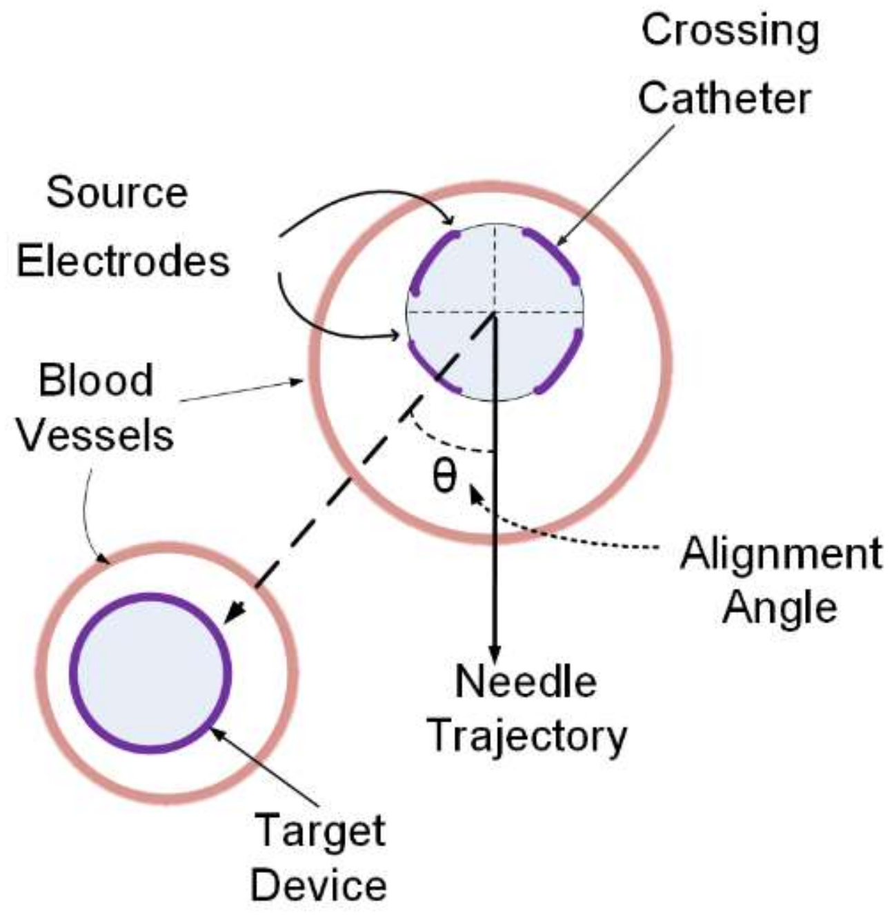
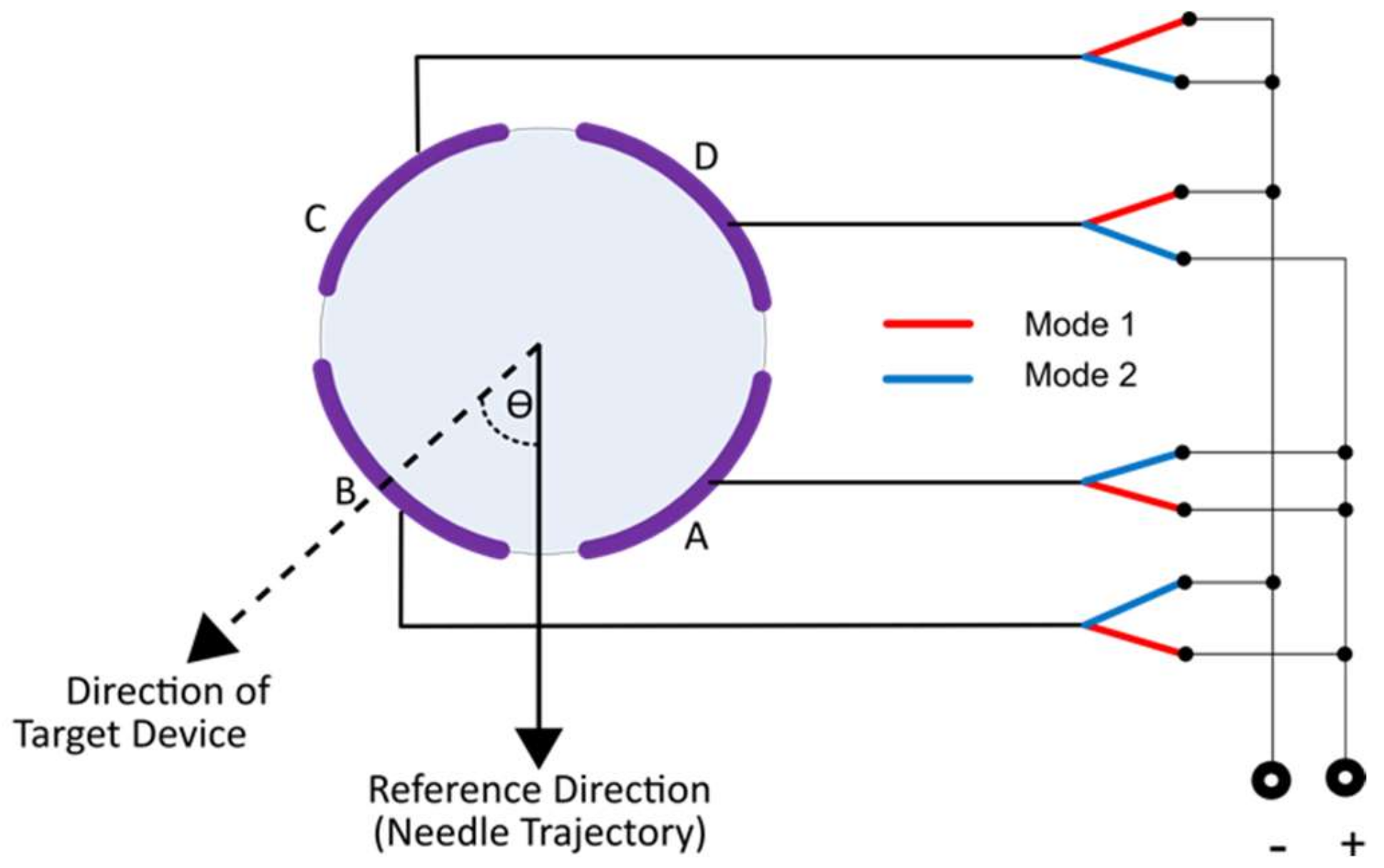
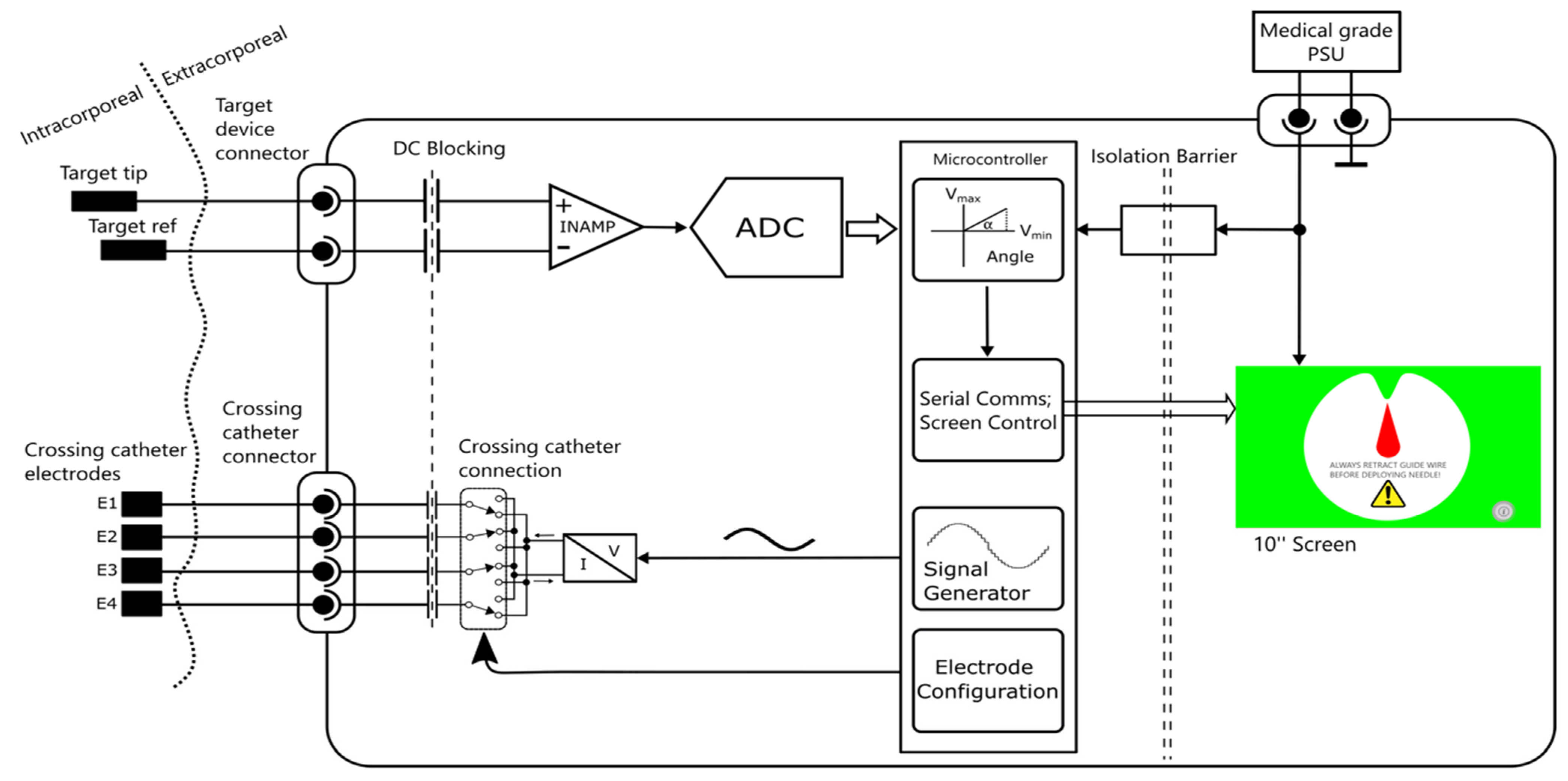
2.1. System Design
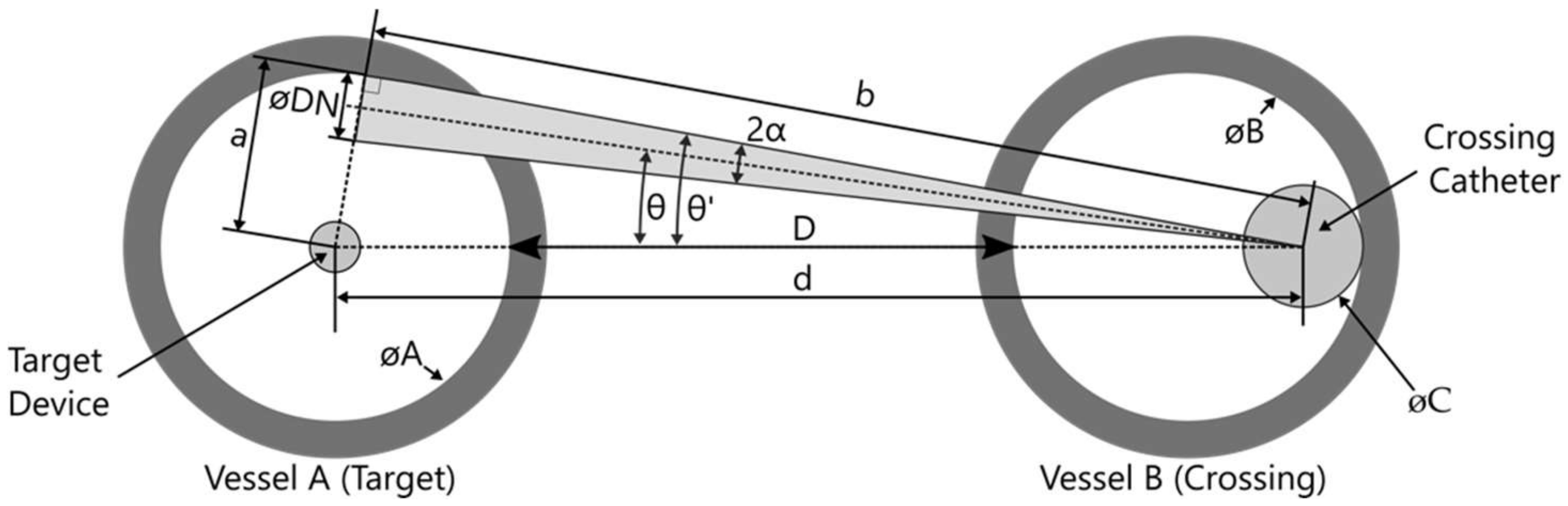
2.2. Vessel Diameters and Geometric Alignment Error in Vessel Positioning
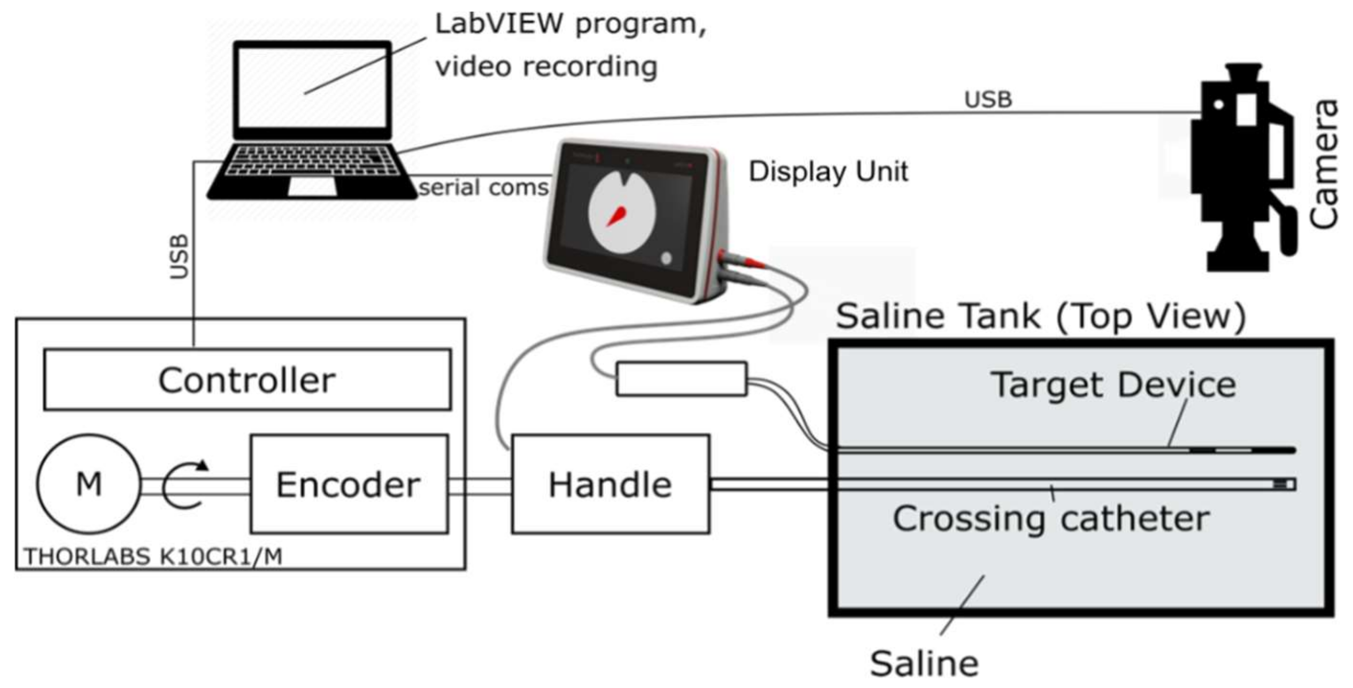
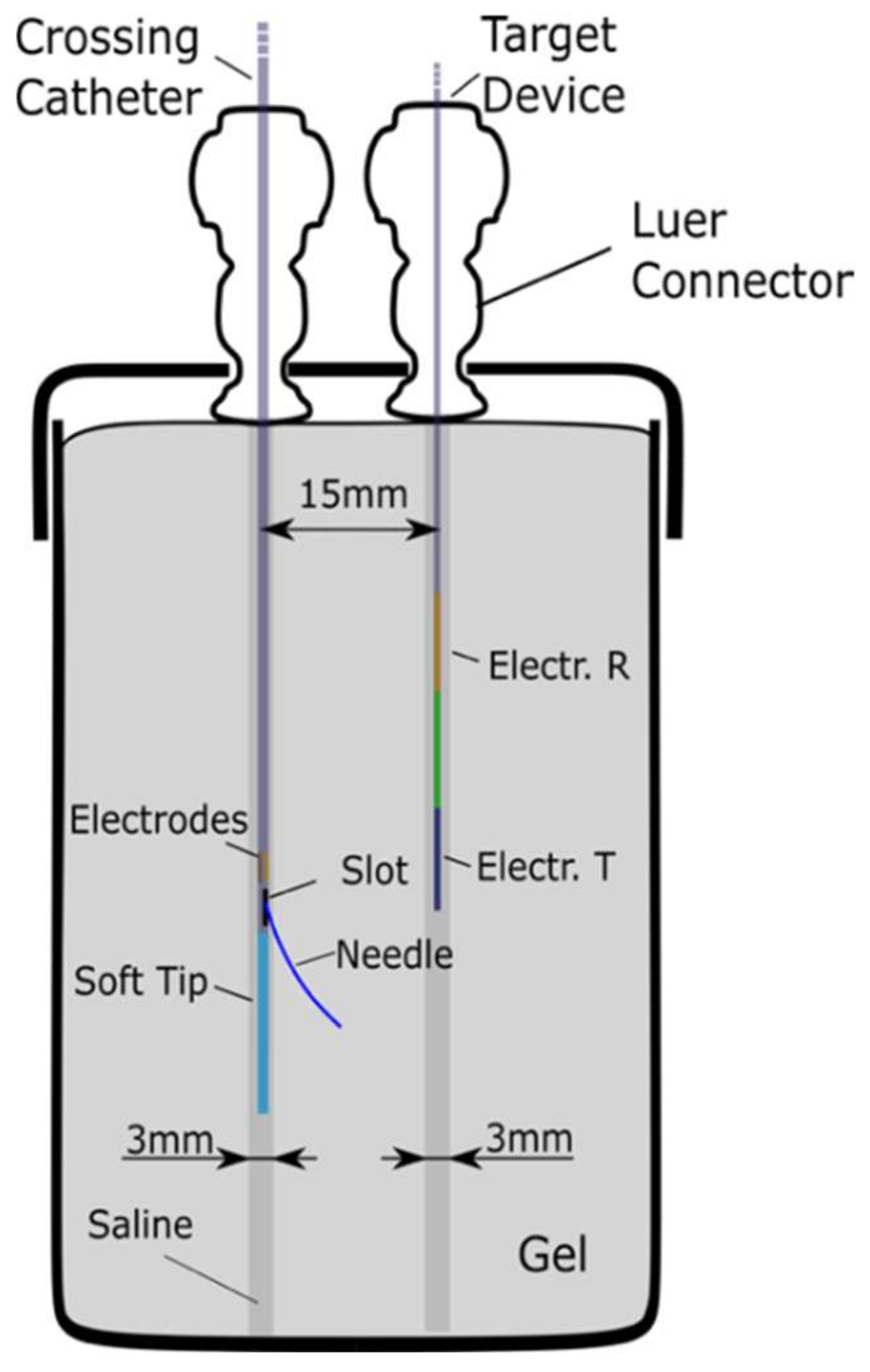
2.3. Evaluation
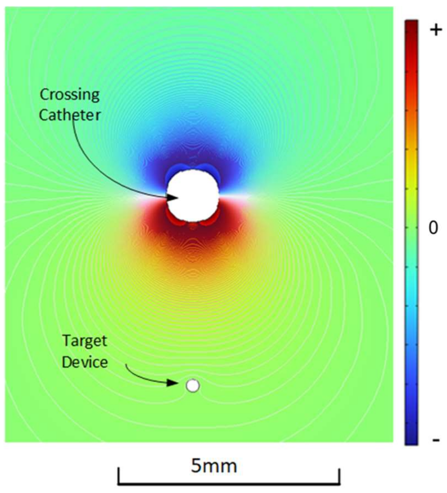
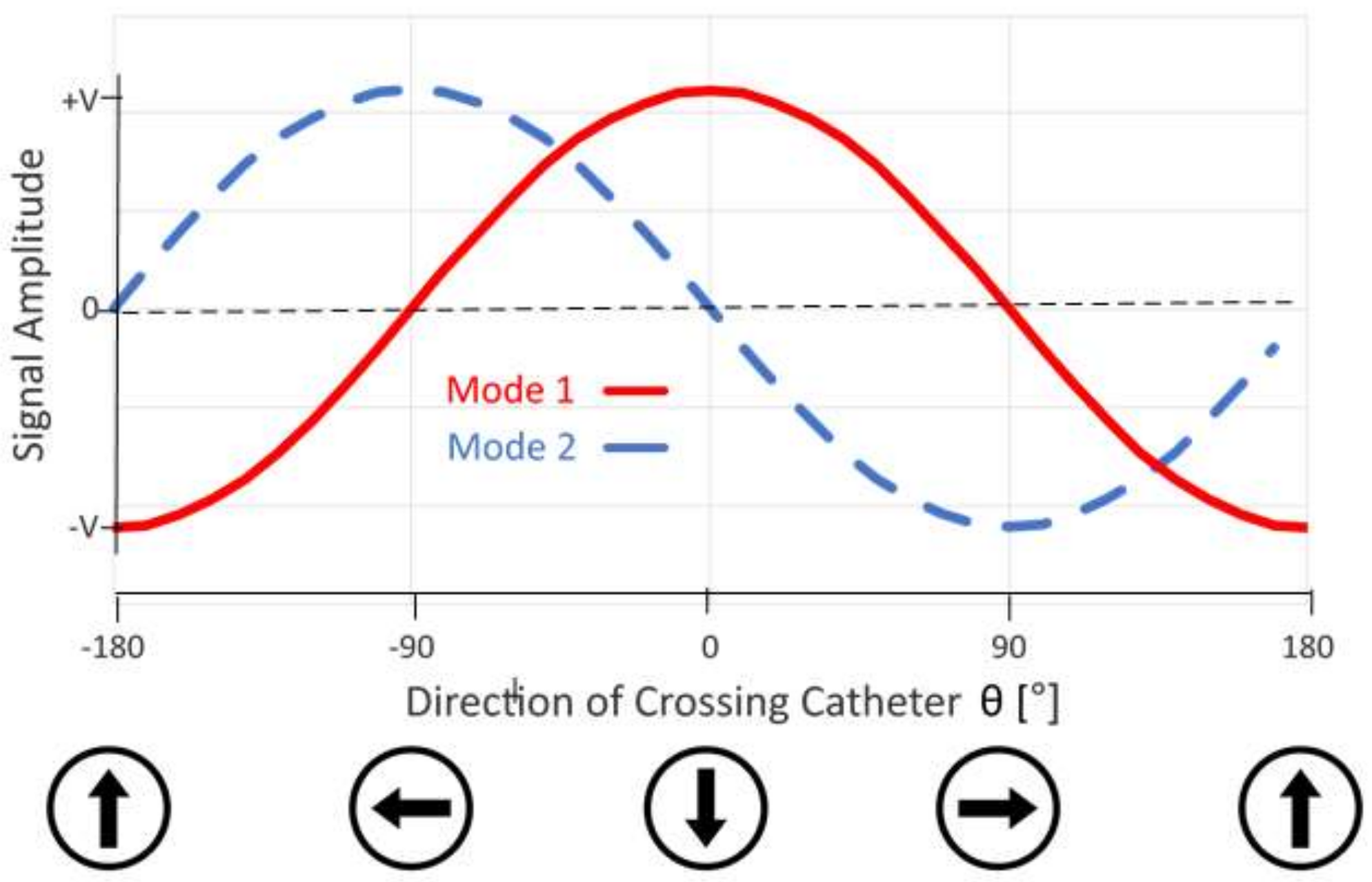
3. Results
In Vitro and Ex Vivo
4. Discussion
5. Conclusions
6. Patents
Author Contributions
Funding
Institutional Review Board Statement
Informed Consent Statement
Acknowledgments
Conflicts of Interest
References
- Bolia, A.; Brennan, J.; Bell, P.R. Recanalisation of femoro-popliteal occlusions: Improving success rate by subintimal recanalization. Clin. Radiol. 1989, 40, 325. [Google Scholar] [CrossRef]
- Al-Jaishi, A.A.; Oliver, M.J.; Thomas, S.M.; Lok, C.E.; Zhang, J.C.; Garg, A.X.; Kosa, S.D.; Quinn, R.R.; Moist, L.M. Patency rates of the arteriovenous fistula for hemodialysis: A systematic review and meta-analysis. Am. J. Kidney Dis. 2013, 63, 464–478. [Google Scholar] [CrossRef] [PubMed]
- Schneider, P.A.; Caps, M.T.; Nelken, N. Re-Entry into the true lumen from the subintimal space. J. Vasc. Surg. 2013, 58, 529–534. [Google Scholar] [CrossRef] [PubMed] [Green Version]
- Jones, R.G.; Morgan, R.A. A Review of the Current Status of Percutaneous Endovascular Arteriovenous Fistula Creation for Haemodialysis Access. Cardiovasc. Interv. Radiol. 2019, 42, 1–9. [Google Scholar] [CrossRef] [PubMed]
- Aslam, M.S.; Allaqaband, S.; Haddadian, B. Subintimal angioplasty with a true re-entry device for treatment of chronic total occlusion of the arteries of the lower extremity. Catheter. Cardiovasc. Interv. 2013, 82, 701–706. [Google Scholar] [CrossRef] [PubMed]
- Gandini, R.; Fabiano, S.; Spano, S. Randomized control study of the Outback LTD reentry catheter versus manual re-entry for the treatment of chronic total occlusions in the superficial femoral artery. Catheter. Cardiovasc. Interv. 2013, 82, 485–492. [Google Scholar] [CrossRef] [PubMed]
- Galassi, R.; Sumitsuji, S.; Boukhris, M.; Emmanouil, S.; Mario, C.D.; Garbo, R.; Spratt, J.C.; Chrisiansen, E.H.; Gangor, A.; Avran, A.; et al. Utility of Intravascular Ultrasound in Percutaneous Revascularization of Chronic Total Occlusions: An Overview. JACC Cardiovasc. Interv. 2016, 9, 1979–1991. [Google Scholar] [CrossRef] [PubMed]
- Loffroy, R.; Falvo, N.; Galland, C.; Fréchier, L.; Ledan, F.; Midulla, M.; Chevallier, O. Intravascular Ultrasound in the Endovascular Treatment of Patients with Peripheral Arterial Disease: Current Role and Future Perspectives. Front. Cardiovasc. Med. 2020, 7, 1–8. [Google Scholar] [CrossRef] [PubMed]
- Dickinson, R.; Popa, S. Surgical Device for the Percutaneous Creation of an Arteriovenous Fistula (AVF). International Patent Application WO2016145202A1, 15 September 2016. [Google Scholar]
- Gabriel, S.; Lau, R.W.; Gabriel, C. The dielectric properties of biological tissues: II. Measurements in the frequency range 10 Hz to 20 GHz. Phys. Med. Biol. 1996, 41, 2251–2269. [Google Scholar] [CrossRef] [PubMed] [Green Version]
- Kordzadeh, A.; Chung, J.; Panayiotopoulos, Y. Cephalic vein and radial artery diameter in formation of radiocephalic arteriovenous fistula: A systematic review. J. Vasc. Access 2015, 16, 506–511. [Google Scholar] [CrossRef] [PubMed]
- Kõiv, H. Developing Tissue Phantom Materials with Required Electric Conductivities. Masters Thesis, Tallin University, Tallin, Estonia, June 2015. [Google Scholar]
- Ištuk, N.; la Gioia, A.; Benchakroun, H.; O’Loughlin, D.; Lowery, A.; Porter, E.; O’Halloran, M. Measurement of Electrical Conductivity of Human Blood at Frequencies Below 100 kHz with Four-electrode Probe Method. In Proceedings of the XXXIV General Assembly and Scientific Symposium of the International Union of Radio Science (URSI GASS), Rome, Italy, 28 August–4 September 2021; pp. 1–4. [Google Scholar] [CrossRef]
- Faes, T.J.C.; van der Meij, H.A.; de Munck, J.C.; Heethaar, R.M. The Electric Resistivity of Human Tissues (100 HZ–10 MHZ): A Meta-Analysis of Review Studies. Physiol. Meas. 1999, 20, 1–10. [Google Scholar] [CrossRef]
- Lui, D.; Popa, S.; Dickinson, R.; Patrone, L. Distal Re-Entry to Treat Lower Limb Chronic Total Occlusions Using a Novel Electrically Guided Re-Entry Catheter. EJVES Vasc. Forum 2020, 51, 5–8. [Google Scholar] [CrossRef] [PubMed]
- Yang, S.; Lok, C.; Arnold, R.; Rajan, D.; Glickman, M. Comparison of Post-Creation Procedures and Costs between Surgical and an Endovascular Approach to Arteriovenous Fistula Creation. J. Vasc. Access 2017, 18, 8–14. [Google Scholar] [CrossRef] [PubMed] [Green Version]
- Arnold, R.J.G.; Han, Y.; Balakrishnan, R.; Layton, A.; Lok, C.E.; Glickman, M.; Rajan, D.K. Comparison between Surgical and Endovascular Hemodialysis Arteriovenous Fistula Interventions and Associated Costs. J. Vasc. Interv. Radiol. 2018, 29, 1558–1566. [Google Scholar] [CrossRef] [PubMed] [Green Version]


Publisher’s Note: MDPI stays neutral with regard to jurisdictional claims in published maps and institutional affiliations. |
© 2022 by the authors. Licensee MDPI, Basel, Switzerland. This article is an open access article distributed under the terms and conditions of the Creative Commons Attribution (CC BY) license (https://creativecommons.org/licenses/by/4.0/).
Share and Cite
Diallo, M.; Eder, C.; Brasier, D.; Popa, S.; Dickinson, R. Electric-Field-Based Guidance for Percutaneous Catheter Vessel Crossing. Sensors 2022, 22, 4928. https://doi.org/10.3390/s22134928
Diallo M, Eder C, Brasier D, Popa S, Dickinson R. Electric-Field-Based Guidance for Percutaneous Catheter Vessel Crossing. Sensors. 2022; 22(13):4928. https://doi.org/10.3390/s22134928
Chicago/Turabian StyleDiallo, Mamadou, Clemens Eder, Daniel Brasier, Sorin Popa, and Robert Dickinson. 2022. "Electric-Field-Based Guidance for Percutaneous Catheter Vessel Crossing" Sensors 22, no. 13: 4928. https://doi.org/10.3390/s22134928