
Design of Lidar Data Acquisition and Control System in High Repetition Rate and Photon-Counting Mode: Providing Testing for Space-Borne Lidar

 ,
,
Abstract
:1. Introduction
2. Data and Methods
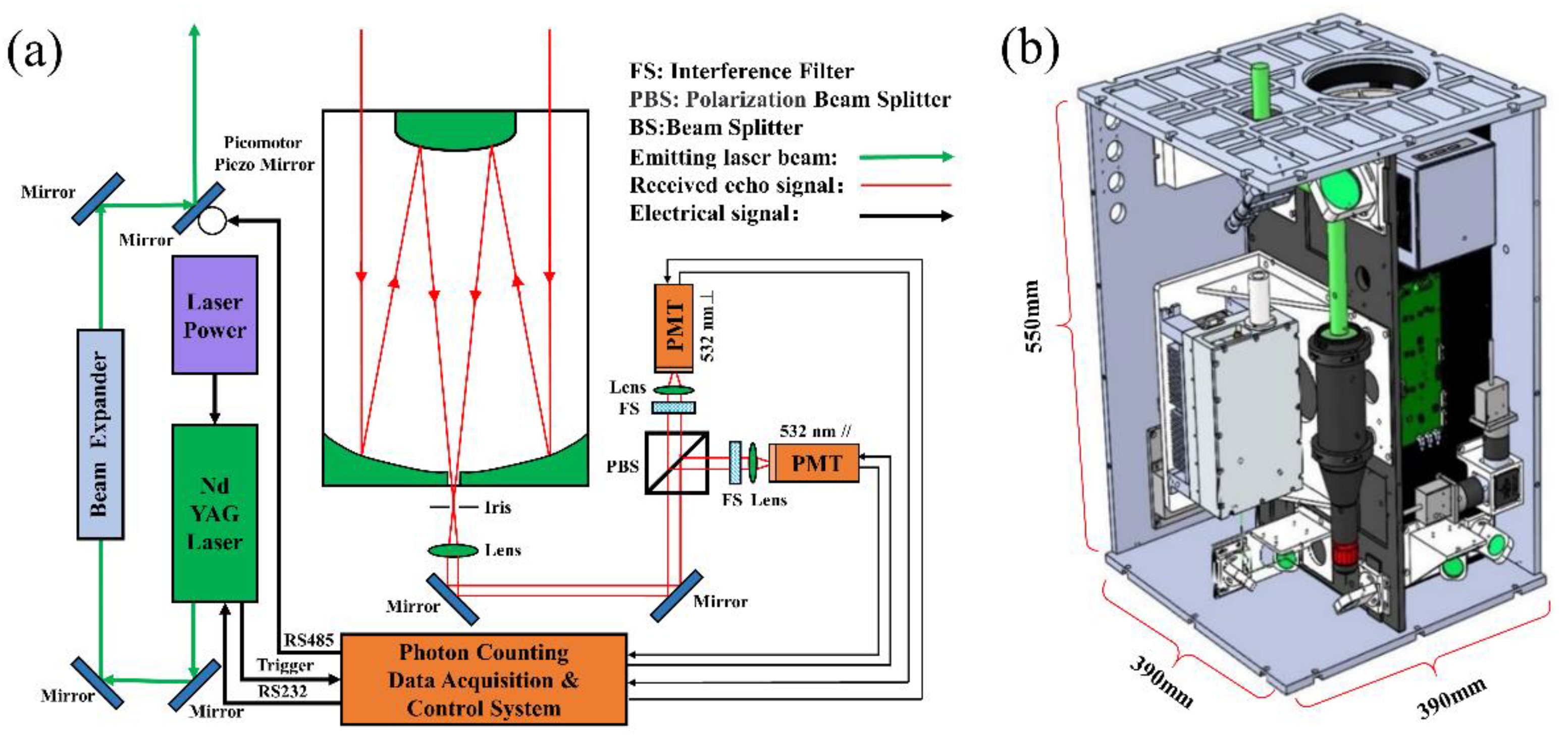
2.1. Lidar Sensor System
2.2. Zynq-Based Acquisition and Control System
- (1)
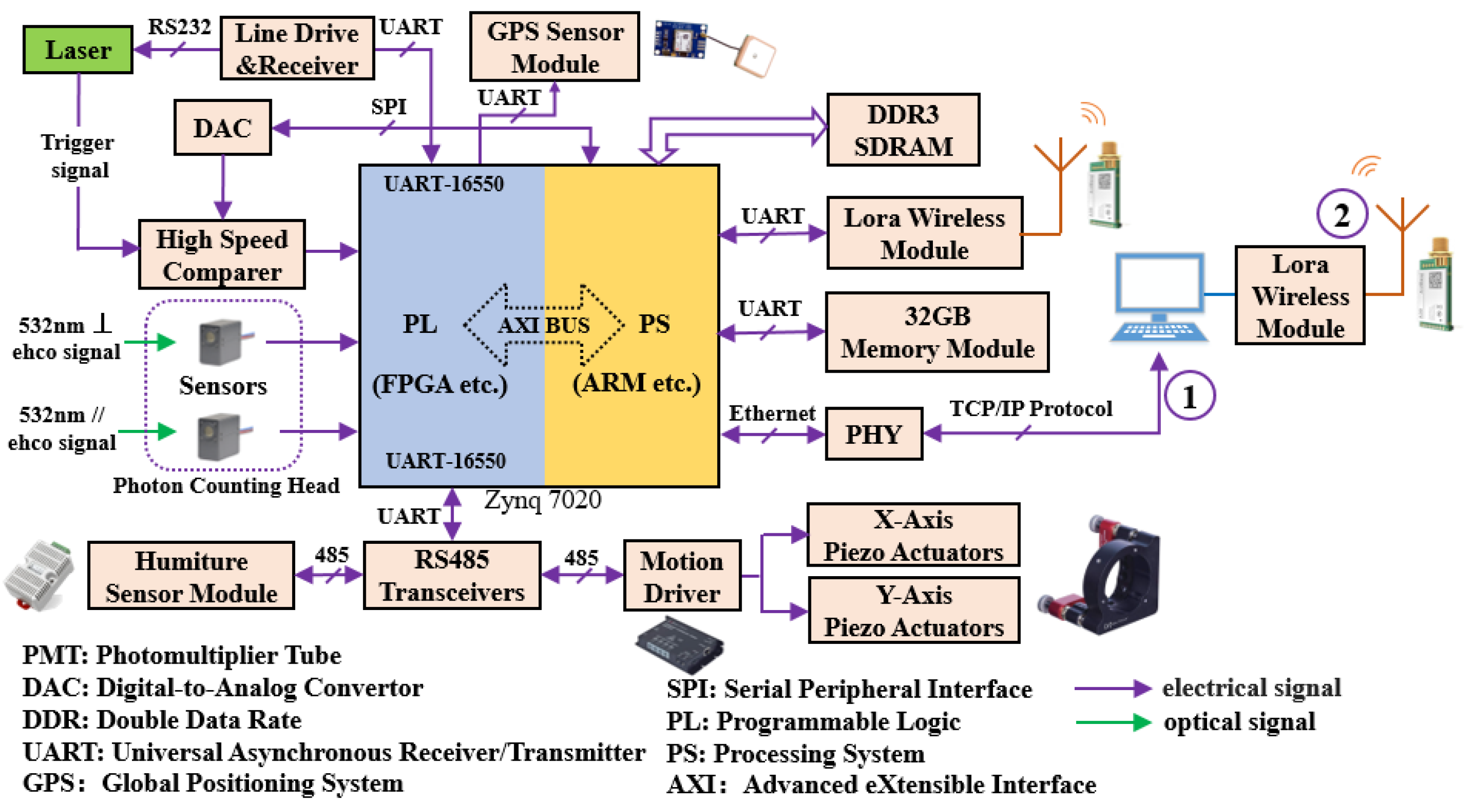
- Hardware design
- (2)
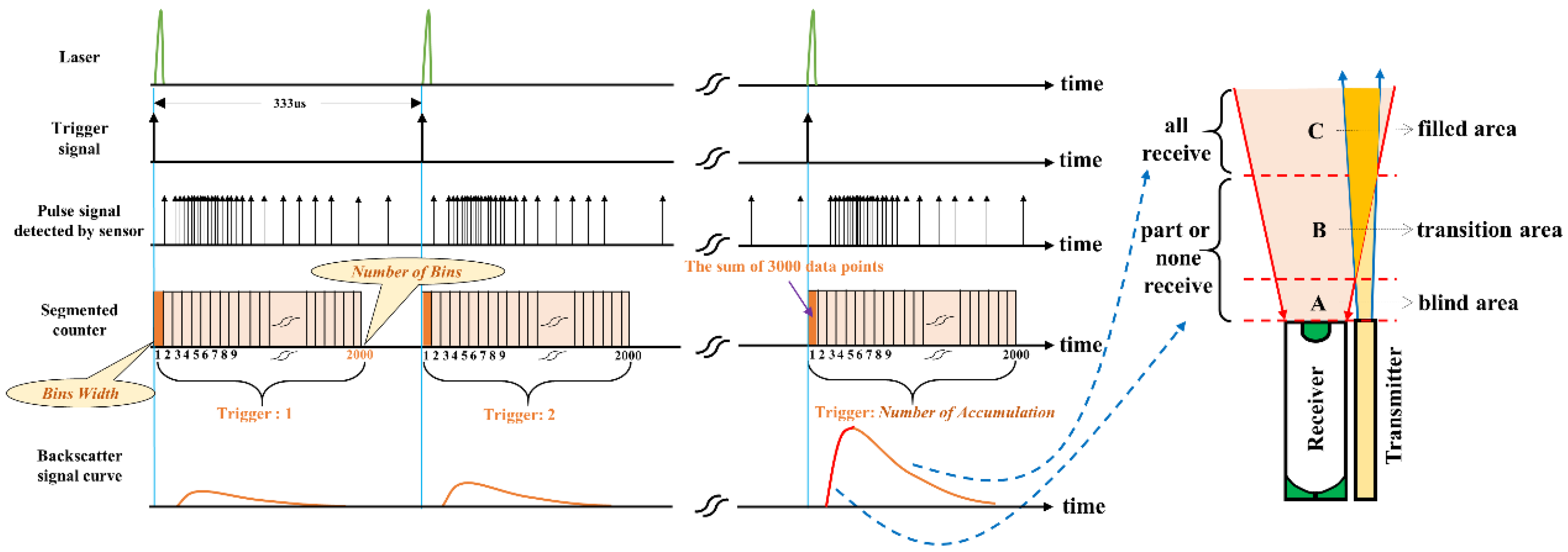
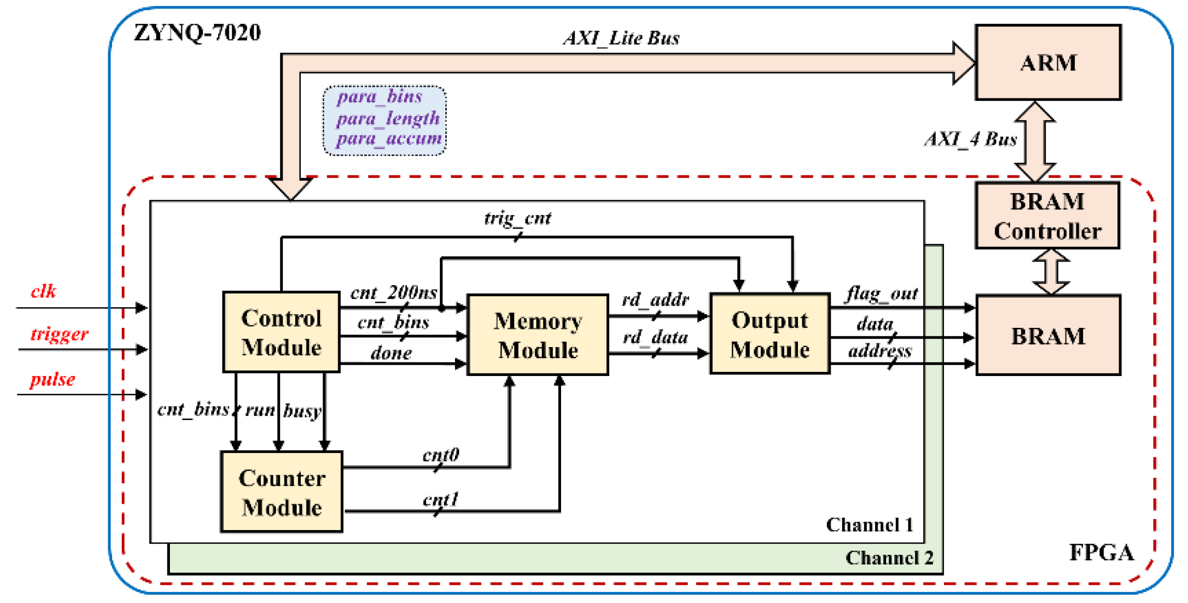
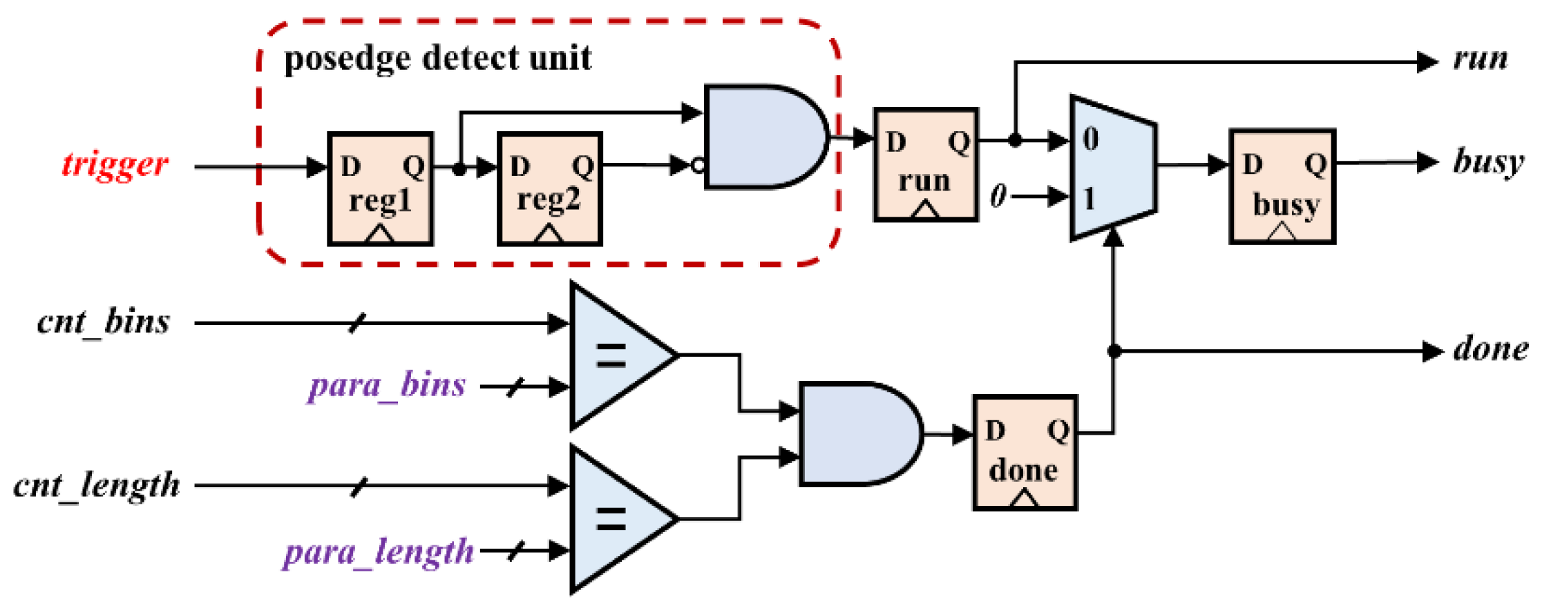
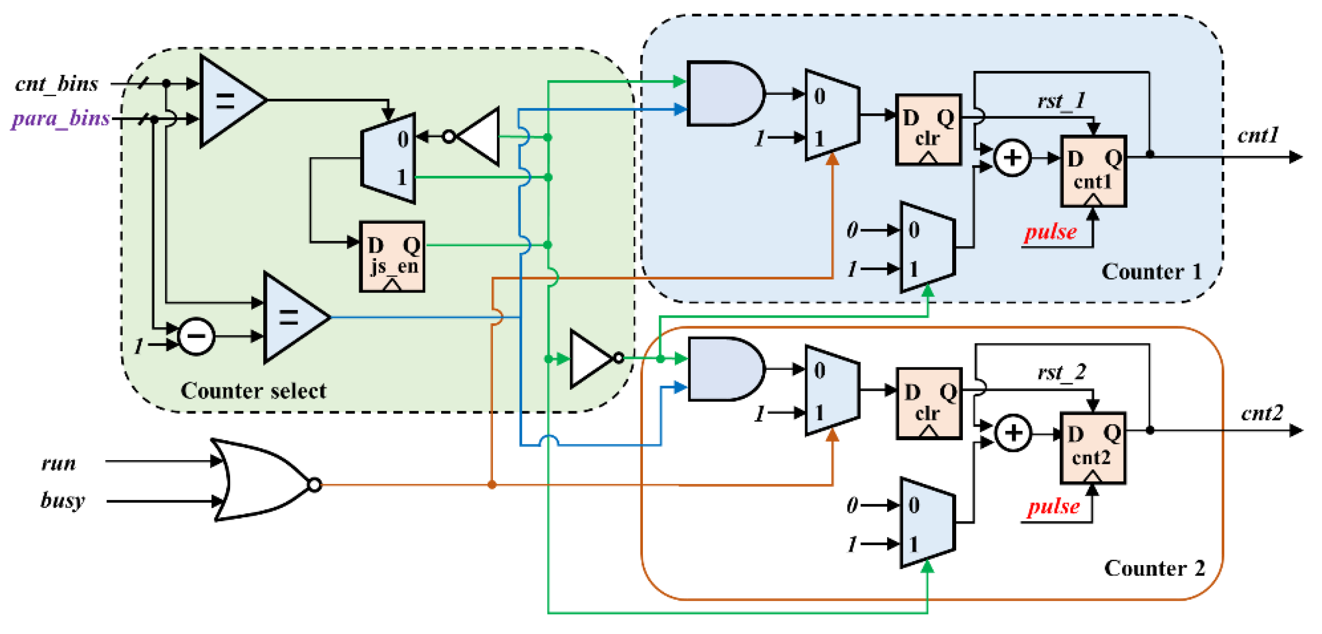
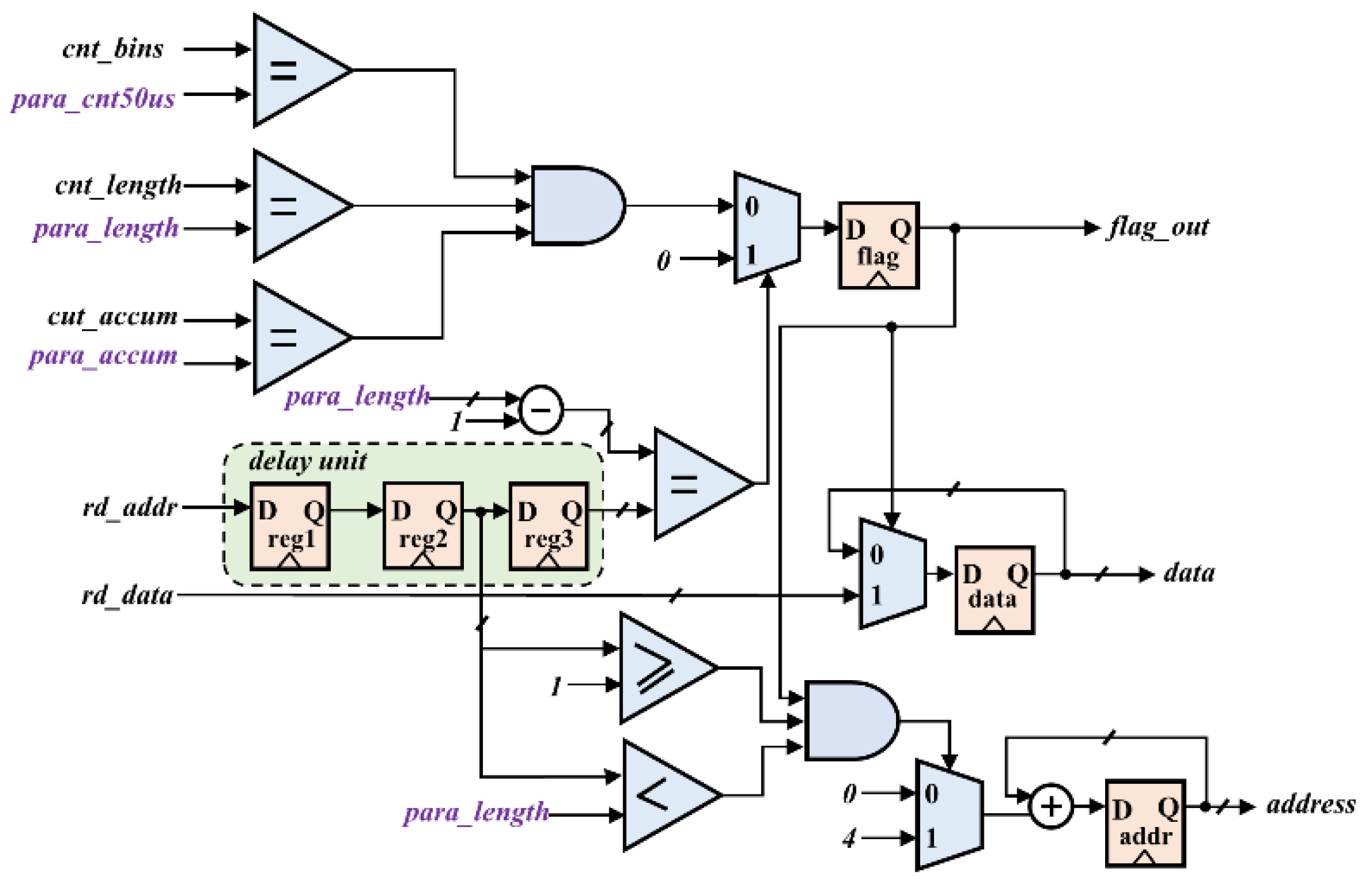
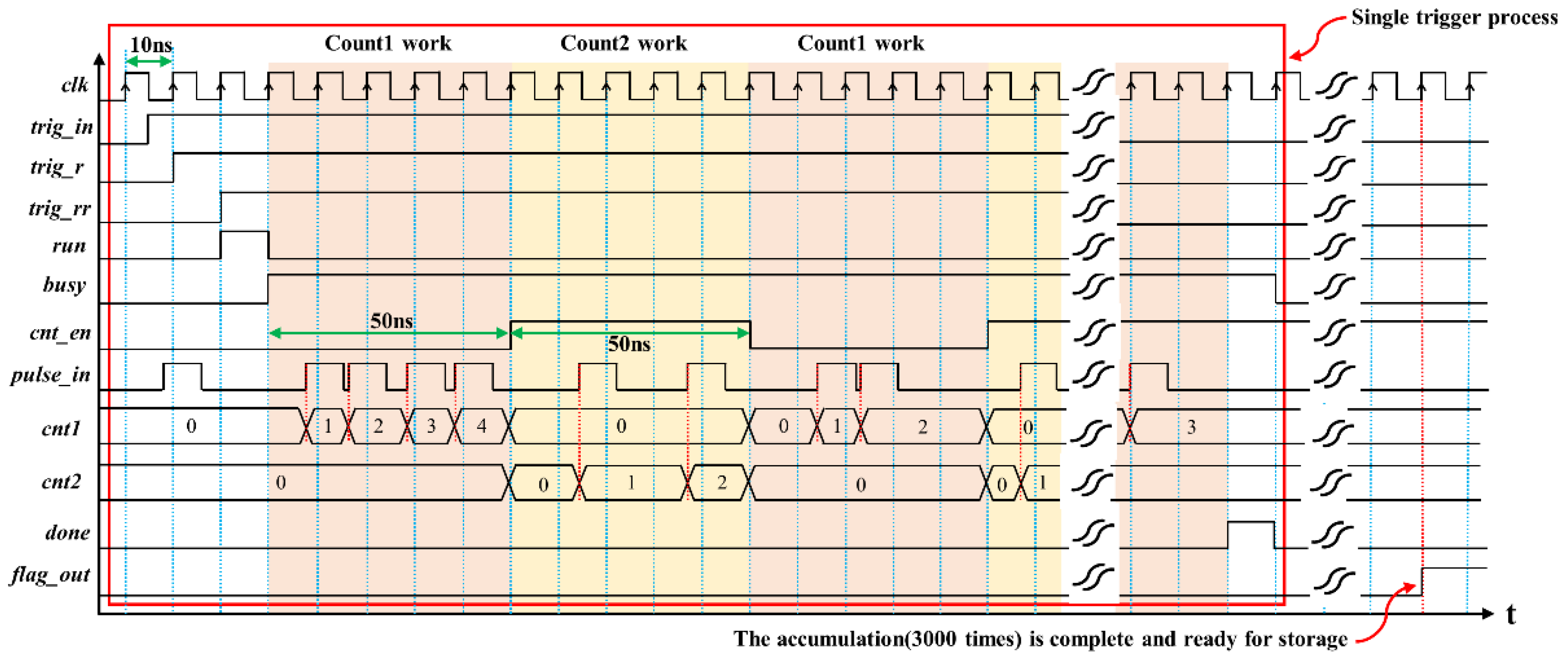
- Principle and logical realization of photon-counting
- (3)
- Software design
3. Results and Analysis
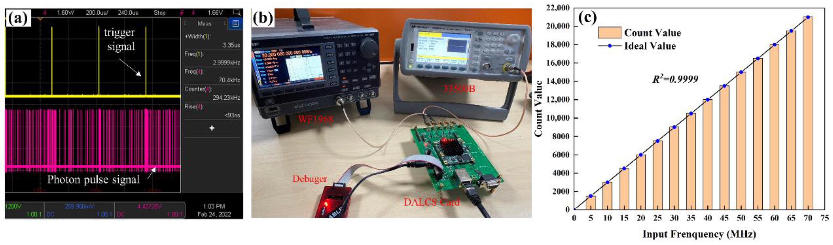
3.1. Data Acquisition Testing and Analysis
3.2. Hardware and Software Collaborative Debug
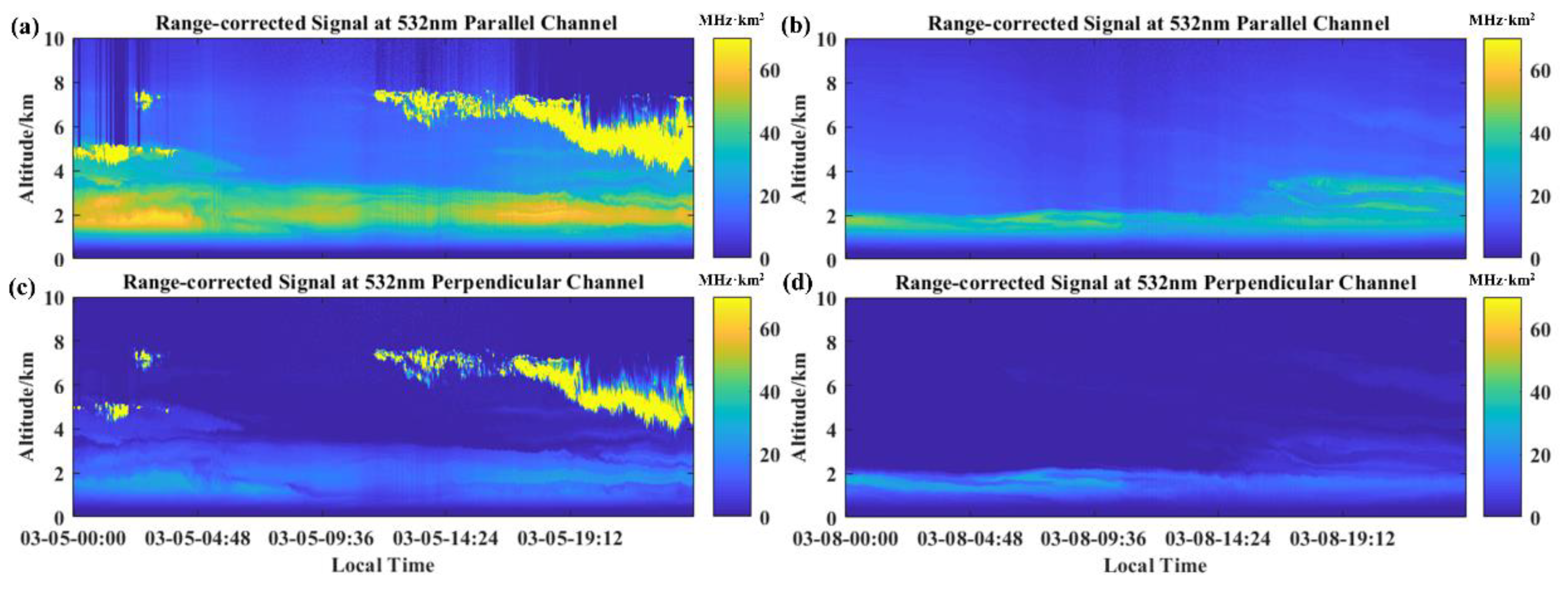
3.3. Application Synthesis Experiment and Analysis
4. Conclusions
Author Contributions
Funding
Institutional Review Board Statement
Informed Consent Statement
Data Availability Statement
Acknowledgments
Conflicts of Interest
References
- Su, T.N.; Li, Z.Q.; Kahn, R. Relationships between the planetary boundary layer height and surface pollutants derived from lidar observations over China: Regional pattern and influencing factors. Atmos. Chem. Phys. 2018, 18, 15921–15935. [Google Scholar] [CrossRef] [Green Version]
- Xie, C.; Nishizawa, T.; Sugimoto, N.; Matsui, I.; Wang, Z. Characteristics of aerosol optical properties in pollution and Asian dust episodes over Beijing, China. Appl. Opt. 2008, 47, 4945–4951. [Google Scholar] [CrossRef]
- Nevzorov, A.A.; Dolgii, S.I.; Nevzorov, A.V.; Makeev, A.P.; Bazhenov, O.E.; Gridnev, Y.V.; Romanovskii, O.A. Lidar monitoring of stratospheric aerosol and ozone at the siberian lidar station. In Proceedings of the 23rd International Symposium on Atmospheric and Ocean Optics—Atmospheric Physics, Irkutsk, Russia, 3–7 July 2017. [Google Scholar]
- Zhao, M.; Fang, Z.; Yang, H.; Cheng, L.; Chen, J.; Xie, C. UAVC: A New Method for Correcting Lidar Overlap Factors Based on Unmanned Aerial Vehicle Vertical Detection. Appl. Sci. 2022, 12, 184. [Google Scholar]
- Devara, P.C.S.; Raj, P.E.; Pandithurai, G.; Dani, K.K.; Sonbawne, S.M.; Rao, Y.J. Differential absorption lidar probing of atmospheric ozone over a tropical urban station in India. Meas. Sci. Technol. 2007, 18, 639–644. [Google Scholar] [CrossRef]
- Yang, H.; Fang, Z.; Cao, Y.; Xie, C.; Zhou, T.; Wang, B.; Xing, K.; Lolli, S. Impacts of Transboundary Dust Transport on Aerosol Pollution in the Western Yangtze River Delta Region, China: Insights Gained From Ground-Based Lidar and Satellite Observations. Earth Space Sci. 2021, 8, 3. [Google Scholar] [CrossRef]
- Comeron, A.; Munoz-Porcar, C.; Rocadenbosch, F.; Rodriguez-Gomez, A.; Sicard, M. Current Research in Lidar Technology Used for the Remote Sensing of Atmospheric Aerosols. Sensors 2017, 17, 1450. [Google Scholar]
- Cao, Y.; Ying, W.; Yang, H.; Fang, Z.; Cheng, L.; Xie, C.; Xing, K. Integrated Design of Lidar Detection and Acquisition System based on FPGA. In Proceedings of the 7th Symposium on Novel Photoelectronic Detection Technology and Applications, Kunming, China, 12 March 2021. [Google Scholar]
- Yang, H.; Fang, Z.; Xie, C.; Cohen, J.; Yang, Y.; Wang, B.; Xing, K.; Cao, Y. Two trans-boundary aerosol transport episodes in the western Yangtze River Delta, China: A perspective from ground-based lidar observation. Atmos. Pollut. Res. 2021, 12, 323–333. [Google Scholar] [CrossRef]
- Winker, D.; Hu, Y.; Pitts, M.; Avery, M.; Getzewich, B.; Tackett, J.; Kittaka, C.; Liu, Z.; Vaughan, M. The CALIPSO Mission: Results and Progress. In Proceedings of the Conference on Lidar Technologies Techniques, and Measurements for Atmospheric Remote Sensing VI, Toulouse, France, 20–21 September 2010. [Google Scholar]
- Kay, J.E.; Bourdages, L.; Miller, N.B.; Morrison, A.; Yettella, V.; Chepfer, H.; Eaton, B. Evaluating andimproving cloud phase in theCommunity Atmosphere Model version5 using space-borne lidar observations. J. Geophys. Res. Atmos 2016, 121, 4162–4176. [Google Scholar]
- Kim, S.-W. Berthier, S., Raut, J.-C., Chazette, P., Dulac, F., and Yoon, S.-C. Validation of aerosol and cloud layer structures from the space-borne lidar CALIOP using a ground-based lidar in Seoul, Korea, Atmos. Chem. Phys. 2008, 8, 3705–3720. [Google Scholar]
- Chuang, T.; Burns, P.; Walters, E.B.; Wysocki, T.; Deely, T.; Losse, A.; Le, K.; Drumheller, B.; Schum, T.; Hart, M.; et al. Space-Based, Multi-Wavelength Solid-State Lasers for NASA’s Cloud Aerosol Transport System for International Space Station (CATS-ISS). In Proceedings of the Conference on Solid State Lasers XXII—Technology and Devices, San Francisco, CA, USA, 3–5 February 2013. [Google Scholar]
- McGill, M.J.; Yorks, J.E.; Scott, V.S.; Kupchock, A.W.; Selmer, P.A. The Cloud-Aerosol Transport System (CATS): A Technology Demonstration on the International Space Station. In Proceedings of the Conference on Lidar Remote Sensing for Environmental Monitoring XV, San Diego, CA, USA, 12–13 August 2015. [Google Scholar]
- Yorks, J.E.; McGill, M.J.; Scott, V.S.; Wake, S.W.; Kupchock, A.; Hlavka, D.L.; Hart, W.D.; Selmer, P.A. The Airborne Cloud-Aerosol Transport System: Overview and Description of the Instrument and Retrieval Algorithms. J. Atmos. Ocean. Technol. 2014, 31, 2482–2497. [Google Scholar] [CrossRef]
- Zielinski, M.; Karasek, K.; Dygdala, R.S. Fast, real-time multichannel scaler, construction and applications. Rev. Sci. Instrum. 1996, 67, 3325–3331. [Google Scholar] [CrossRef]
- Zielinski, M.; Dygdala, R.S.; Karasek, K.; Zawadzka, A. Real-time multichannel scaler measurement of oscillator instabilities. Rev. Sci. Instrum. 2000, 71, 2577–2581. [Google Scholar] [CrossRef]
- Guzik, Z.; Borsuk, S.; Traczyk, K.; Plominski, M.J.I.t.o.n.s. TUKAN-an 8K pulse height analyzer and multi-channel scaler with a PCI or a USB interface. IEEE Trans. Nucl. Sci. 2006, 53, 231–235. [Google Scholar] [CrossRef]
- Guzik, Z.; Borsuk, S.; Traczyk, K.; Plominski, M. Enhanced 8K pulse height analyzer and multi-channel scaler (TUKAN) with PCI or USB interfaces. In Proceedings of the Nuclear Science Symposium/Medical Imaging Conference, Rome, Italy, 16–22 October 2004. [Google Scholar]
- Kim, M.J.; Choi, J.H.; Hong, D.G. Dose and dose rate dependence of time-resolved OSL from Korean paleosol quartz. Radiat. Meas. 2011, 46, 1518–1521. [Google Scholar] [CrossRef]
- EASY-MCS Multichannel Scaler. Available online: https://www.ortec-online.com/products/electronics/counters-timers-rate-meter-and-multichannel-scaling-mcs/easy-mcs (accessed on 9 January 2022).
- Multi-Channel Scaler Cards Improve Data Collection. Available online: https://spinoff.nasa.gov/Spinoff2004/er_2.html (accessed on 9 January 2022).
- Zhang, Y.; Yi, F.; Kong, W.; Yi, Y. Slope characterization in combining analog and photon count data from atmospheric lidar measurements. Appl. Opt. 2014, 53, 7312–7320. [Google Scholar] [CrossRef]
- Zhang, C.; Sun, X.; Zhang, R.; Liu, Y. Simulation and assessment of solar background noise for space-borne lidar. Appl. Opt. 2018, 57, 9471–9479. [Google Scholar] [CrossRef]
- Kunz, G.J.; Deleeuw, G. Inversion of lidar signals with the slope method. Appl. Opt. 1993, 32, 3249–3256. [Google Scholar] [CrossRef]
- Fernald, F.G. Analysis Of Atmospheric Lidar Observations—Some Comments. Appl. Opt. 1984, 23, 652–653. [Google Scholar] [CrossRef]
- Liu, H.; Wang, Z. An iterative calibrating method for airborne atmospheric detection lidar based on the klett forward integral equation. Opt. Commun. 2019, 452, 476–480. [Google Scholar] [CrossRef]
- Liu, J.; Feng, J. Design of embedded digital image processing system based on ZYNQ. Microprocess. Microsyst. 2021, 83. [Google Scholar] [CrossRef]
- Xue, T.; Zhu, J.; Gong, G.; Wei, L.; Luo, Y.; Li, J. The Design and Data-Throughput Performance of Readout Module Based on ZYNQ SoC. IEEE Trans. Nucl. Sci. 2018, 65, 1169–1179. [Google Scholar] [CrossRef]
- 12-bit Low Power Digital-to-Analog Converters with Power Down and Internal Reference. Available online: https://www.ti.com/lit/ds/symlink/tlv5630.pdf (accessed on 2 March 2022).
- Very Fast Single-Supply TTL/CMOS Comparators. Available online: https://www.analog.com/media/en/technical-documentation/data-sheets/ADCMP600_601_602.pdf (accessed on 6 March 2022).
- AXI UART16550. Available online: https://www.xilinx.com/products/intellectual-property/axi_uart16550.html (accessed on 11 March 2022).
- Tatsuo, S. High-Speed and High-Resolution Photon-Counting for Near-Range Lidar; Nikolay, B., Anton, N., Eds.; IntechOpen: London, UK, 2018. [Google Scholar]
- Adamiec, G.; Heer, A.J.; Bluszcz, A. Statistics of count numbers from a photomultiplier tube and its implications for error estimation. Radiat. Meas. 2012, 47, 746–751. [Google Scholar] [CrossRef]


| Parameter | MCS-PCI | EASY-MCS | AMCS-USB | Licel TR20-160 |
|---|---|---|---|---|
| Minimum bins width | 100 ns | 100 ns | 50 ns | 50 ns |
| Maximum number of bins | 64 K | 64 K | 4 K | 32 K |
| Maximum number of accumulation | 4 M-1 | 4 M-1 | 32 K | 2 M-1 |
| Wired communication interface | PCI | USB 2.0 | USB 1.1 | 10/100 Ethernet |
| Control function (wireless, storage, self-test, collimation, etc.) | No | No | No | No |
| IPC is needed when working | Yes | Yes | Yes | Yes |
| Part | Parameters | Value | Part | Parameters | Value |
|---|---|---|---|---|---|
| Laser emitting unit | Laser wavelength/nm | 532.18 | Data acquisition and lidar control unit | Detector | PMT |
| Divergence angle/μrad | 113 | Pulse width/ns | 10 | ||
| Single pulse laser energy/mJ | 1 | Pulse-pair resolution/ns | 20 | ||
| Pulse repetition rate/Hz | 3 k | Acquisition mode | Photon-counting | ||
| Line width/pm | 45 | Number of Channels | 2 | ||
| Pulse width /ns | 13 | Maximum counting rate/MHz | 250 | ||
| Optical receiving unit | Telescope diameter/mm | 125 | Minimum bins width/ns | 20 | |
| Iris/mm | 0.5 | Maximum number of bins | 4 M-1 | ||
| Field of view/μrad | 280 | Maximum number of accumulation | 4 M-1 | ||
| Telescope focus distance/mm | 1430 | Data storage mode | Store or Sending | ||
| Filter bandwidth/nm | 0.3 |
Publisher’s Note: MDPI stays neutral with regard to jurisdictional claims in published maps and institutional affiliations. |
© 2022 by the authors. Licensee MDPI, Basel, Switzerland. This article is an open access article distributed under the terms and conditions of the Creative Commons Attribution (CC BY) license (https://creativecommons.org/licenses/by/4.0/).
Share and Cite
Cheng, L.; Xie, C.; Zhao, M.; Li, L.; Yang, H.; Fang, Z.; Chen, J.; Liu, D.; Wang, Y. Design of Lidar Data Acquisition and Control System in High Repetition Rate and Photon-Counting Mode: Providing Testing for Space-Borne Lidar. Sensors 2022, 22, 3706. https://doi.org/10.3390/s22103706
Cheng L, Xie C, Zhao M, Li L, Yang H, Fang Z, Chen J, Liu D, Wang Y. Design of Lidar Data Acquisition and Control System in High Repetition Rate and Photon-Counting Mode: Providing Testing for Space-Borne Lidar. Sensors. 2022; 22(10):3706. https://doi.org/10.3390/s22103706
Chicago/Turabian StyleCheng, Liangliang, Chenbo Xie, Ming Zhao, Lu Li, Hao Yang, Zhiyuan Fang, Jianfeng Chen, Dong Liu, and Yingjian Wang. 2022. "Design of Lidar Data Acquisition and Control System in High Repetition Rate and Photon-Counting Mode: Providing Testing for Space-Borne Lidar" Sensors 22, no. 10: 3706. https://doi.org/10.3390/s22103706