
Embedded Computation Architectures for Autonomy in Unmanned Aircraft Systems (UAS)

 , , , ,
Abstract
:1. Introduction
2. Relating UAS Applications and Autonomy
2.1. Existing Attempts to Define Autonomy in Autonomous Systems
“An unmanned system’s own ability of integrated sensing, perceiving, analyzing, communicating, planning, decision-making, and acting/executing, to achieve its goals as assigned by its human operator(s) through designed Human-Robot Interface or by another system that the unmanned system communicates with.”
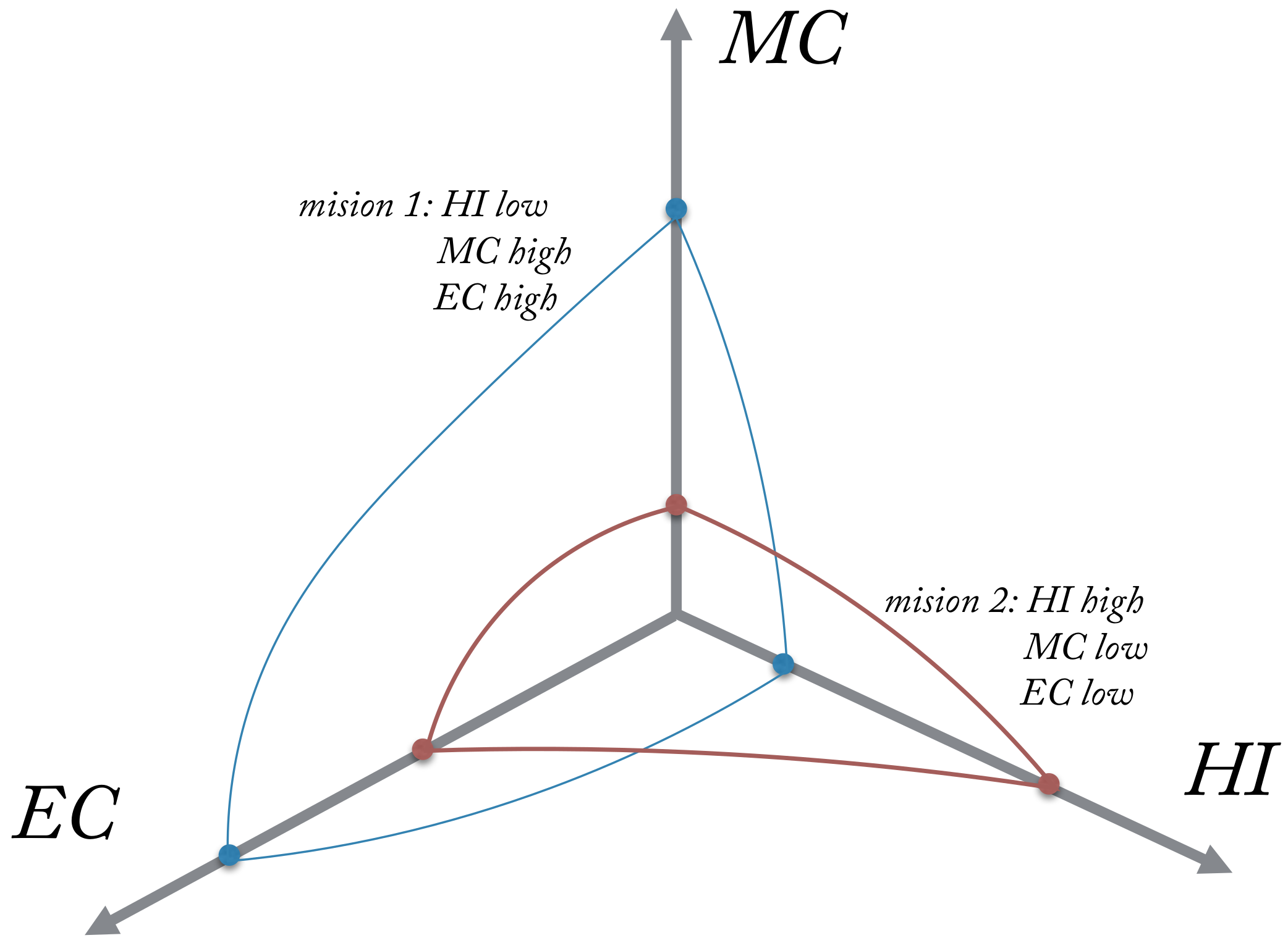
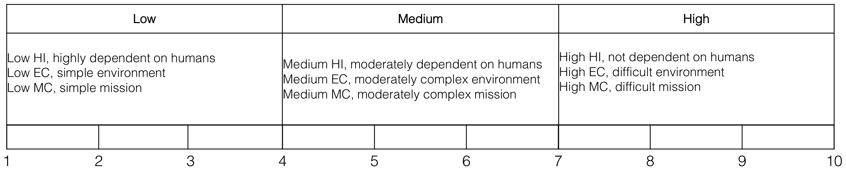
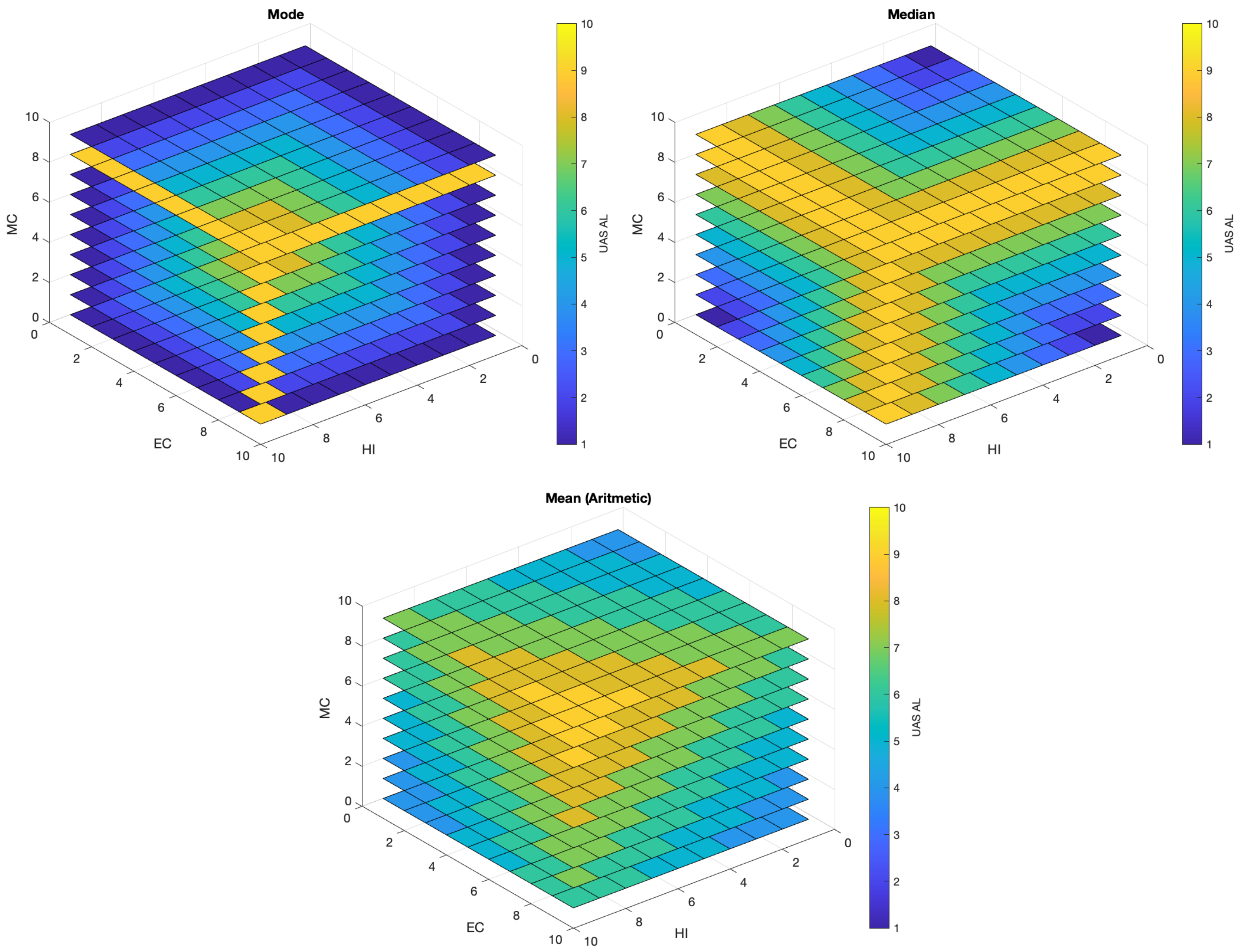
- HI: UAS degree of sensing environmental phenomena, UAS degree of understanding and analysing perceived situations, what/when a larger portion of the mission plan is generated by the UAS, UAS ability to generate high-level, complex plans as opposed to low-level, straightforward plans, degree of communication with the UAS and number of decisions per unit of time.
- MC: Mission time constraint, precision constraints and repeatability in navigation, manipulation, detection, perception, level of collaboration required, concurrence and synchronization of events and behaviours, resource management and ammunition and authority hierarchy for data access and plan execution.
- EC: Electromagnetic interference, use of absolute and fiducial reference points to facilitate navigation and reduce the complexity, objects size, type, density and intent; including natural or man made, lighting conditions and man-made structures.
2.2. UAS Applications and Autonomy
3. Definition and Categorisation of Onboard Unmanned Aircraft Tasks
Tasks Definitions and Specifications
- Flight control level: actuator control, stabilisation and control loops, low level sensor readings, state estimation and telemetry communication.
- Navigation and guidance level: Static or dynamic path planning, trajectory tracking, waypoint navigation, obstacle avoidance, terrain following, vision-based navigation.
- Application level: Application specific sensor readings, aerial sampling, application specific camera tasks.
- Safety level: Sense and avoid, fault detection and identification, emergency procedures and airspace management
- Mission level: Energy and storage management, computational resource management, health management, decision making and communication management.
- Actuator control: This task could be considered as the lowest-level task on an unmanned aircraft. It involves the translation of software parameters into electrical signals for each actuator. It requires a few to tens of thousands of pulses per minute and be independent of any task that might prevent its real-time execution. Its computational load is usually negligible due the use of dedicated hardware components for each actuator.
- State estimation and stabilisation control loops: State estimation typically relies on a type of Kalman filter. Depending on the number of states and parameters in the aircraft dynamic model, this task could require a significant amount of computational resources. The amount of computation is mainly related to matrix operations. Floating-point computations can be very meticulous to reach accuracy and stability requirements. The control of attitude, position and speed mainly relies on close-loop control. Typical implementations involve multichannel PID approaches [39]. Due to the nature of this function (low-level), most of the computational demands are handled by using dedicated embedded hardware. However, researchers have proposed architectures where autonomy levels are linked to different layers of control [40], in which more computational resources are necessary.
- Low level sensor readings: This low level function accesses various digital and analog ports, such as I2C, analog to digital converters (ADCs), GPIO, RS232, PWM, USB, etc., reading and conditioning the signal before it is used by other tasks. In general terms, this function samples the ports converting sensor information into numerical values that are used by other onboard tasks. Different sample rates and scale factors are used for every sensor. In most cases, dedicated hardware is used to implement this function which minimises the requirement for computational resources. Dedicated chips handle signal level conversion, packing and unpacking of bits, clock synchronisation, device interfacing, etc.
- Telemetry communications: Traditionally, this task automates the process of sending data to a remote receiving equipment for monitoring. The medium can be either wired or wireless, although in UAS wireless is the most common medium using radio modems followed by 802.1xx (wifi). Nowadays, this task has evolved from simply sending data through a medium. Functions such as byte marshalling (or serialization), error checking, heart beat generation and monitoring and low level data compression are now an integral part of this task. Telemetry communications in most cases provide vital information to access whether the communication link is healthy or not, so the appropriate failsafe action is triggered.
- Vision-based navigation: This type of navigation have gained significant importance in recent years [41,42], primarily as a navigation method in GPS-denied environments (indoor and outdoor). Techniques derived from space localization such as visual odometry [43,44] or SLAM [45,46,47] have been tested with acceptable performances. Other techniques used in this approach are stereo vision [48,49], structure-from-motion [50,51], bio-inspired opticflow [52,53,54] and target relative navigation [55,56]. Vision-based navigation typically involves estimation of the UAS pose by computing ego-motion (camera motion). Once the aircraft state vector has been computed, control laws can be used to stabilise and guide the aircraft.
- Path planning and trajectory tracking: Path planning often involves finding the optimal trajectory between two points with or without consideration of obstacles. These techniques can be static (executed once) or dynamic (replanning in the event of obstacles), and involve finding the shortest path under specific constraints: (a) geometrical or kinematic constraints due to the design of the unmanned aircraft, (b) dynamics constraints defined by the environment (wind, unexpected obstacles). The trajectory tracking involves the definition of the control commands necessary to follow a set of curves/trims that respect the aerodynamic of the aircraft [57]. These curves constitute the guidance primitives for the autopilot so that it can steer the aircraft to follow a specific trajectory. Typically, these approaches rely on probabilistic, deterministic or heuristic numerical methods to compute the path while providing trajectory waypoints that already take into account the UAS constraints. Hardware implementations for discrete methods have already been investigated for deterministic and heuristic path-planning with FPGA implementation [58], but not many are investigating hardware versions of probabilistic methods [59].
- Waypoint navigation: This task involves the following of preplanned or manually provided waypoints (GPS coordinates). The task will generate the control commands to steer the vehicle between two consecutive waypoints. Since there is an assumption of straight line motion between two consecutive points and no strict consideration for the aircraft dynamic and kinematics constrains, this task could be considered as a simplistic version of a trajectory tracker.
- Obstacle avoidance and terrain following: Obstacle avoidance, as the name suggests, implies the detection and following avoidance of obstacles present in the flight path. Many passive and active sensors can be used for this purpose, and a number of algorithms have proven effective in this domain [60,61]. Terrain following compares measurements from onboard sensors with a database terrain map so the minimum clearance is respected. It can also be used for drift-free localisation purposes in case of GPS-denied environments.
- Application specific sensor readings: The distinction between low level and application specific sensor readings lies in the criticality of enabling or disabling the task. For instance, disabling accelerometers, GPS or compass readings will, in most cases, have catastrophic consequences for the UAS. On the other hand, disabling (on demand) a camera or a Lidar should not be critical for the overall navigation, unless they are used as main navigation sensor. This ability to disable a task based on the information provided by other tasks is essential in autonomous systems. For instance, stopping the Lidar or high resolution camera when onboard storage is running low, before it slows down the computer or causes a software critical failure, should be an feature in highly autonomous UAS.
- Application specific camera tasks: Applications that make use of cameras (video or still) are on the rise. These applications involve the recording or transmission of HD video or images that might or might not include onboard data (such as GPS, UAS orientation or altitude). Within this category, it is worth to mention several applications that have seen an increase in use such as, videography for the filming industry or sport events [62], target recognition and tracking using machine vision cameras [63], aerial photography for surveying [64], precision agriculture or real estate [65]. Depending on the configuration, each application will have an impact on the onboard processing requirements, data storage, communications and command and control links. For instance, if onboard processing is required, then computational and power resources onboard must meet the demand of applications such as target tracking [66] or video encryption [67], amongst others.
- Aerial sampling: Assessment of air quality is an important area of research that studies the link between poor air quality and adverse health outcomes [68]. Sampling the air close to source of pollutants may not always be possible as it can be too dangerous or risky for humans. The use of a small, lightweight unmanned aircraft can minimise the risk for humans and provide more accurate information on aerosol distribution throughout the atmospheric column. Similarly, the modality of collection and processing the samples has an impact on the computational, communications and power resources needed onboard the aircraft.
- Sense and avoid: This task is fundamental for achieving high levels of autonomy onboard unmanned aircraft. Many of the benefits provided by UAS will come from applications that require operations beyond line-of-sight. Operating UAS in civilian airspace, which is a complex environment, is not trivial [69]. In this task we can also include a form of obstacle avoidance, either dynamic or static. Whether avoiding other aircraft or obstacles on the path, there are common functional blocks in a sense-and-avoid system that can be reused. A sense-and-avoid system can be cooperative or uncooperative, and typically encompasses sensors, detection and tracking algorithms and evasive control measures [21].
- Fault detection and diagnosis: This is mission critical if robust and safe UAS operations are to be conducted, and a key consideration when demonstrating dependability, safety and reliability of the UAS. Real-time techniques are preferred as they make it possible to instantly analyse onboard faults and trigger the best strategy to deal with the event. The multiple-model adaptive estimation (MMAE) approach has been applied successfully to deal with fault detection and diagnosis (FDD) problems in various flight scenarios [70,71,72]. Other approaches, have dealt with the high computational requirements of these techniques by using different estimators without loss of performance [73]. Health-management and mitigation strategies for multiple UAS have also been proposed [74].
- Emergency procedures: With the increased presence of unmanned aircraft flying over people and infrastructure assets, a robust and trusted system that deal with onboard emergencies is an essential capability. To intelligently and safely trigger a strategy to deal with onboard failures is one of the main challenges in manned and unmanned aviation safety. A system that can land an aircraft or adapt its flight control in response to an engine failure, actuator faults, loss of sensor readings or any other onboard failure is key in highly autonomous aircraft [26,75]. A system like this, will likely require a number of processing stages, each demanding some computational capability from onboard resources [76].
- Airspace management: The increasing number of unmanned aircraft flying in civilian airspace means that future airspace will be characterised by a combination of manned and unmanned aircraft. The mandatory nature of this system will be evident, because the current system for UAS authorizations is not scalable for the vast number of applications anticipated by government and industry [37,77,78]. New technologies onboard aircraft as well as ground support systems will need to be developed [13,79]. Onboard aircraft, this will mean new sensors and software tools that allows interaction and safe separation between them. This function is closely integrated with other subsystems such as guidance and navigation, decision making and collision avoidance.
- Health management: Is the ability of a system to prevent, detect, diagnose, respond to and recover from conditions that may change the nominal operation of that system [80]. In that sense, we make the distinction between fault detection and identification (FDI) and health management, as FDI is part of the overall health management system. Health management systems are an integral part of most aircraft [81,82], however, this is a relatively novel concept in UAS. Early attempts to develop health management systems for UAS were focused on teams for persistent surveillance operations [83]. Approaches based on Bayesian networks for aircraft health-management have also been proposed in the literature [34,84]. Current challenges include efficient algorithms, embedded computing for real-time processing and simulation, validation and verification [85].
- Communication management: This task deals with strategies to recover or maintain the communication link between unmanned aircraft and the ground control station. It provides the ability to adjust data compression based on available channel throughput, enables data encryption when required and implements error checking for data integrity. It computes metrics to estimate the quality of the communication link, that then can be used by other subsystems for decision making.
- Energy and storage management: Managing energy consumption and distributing it intelligently to different subsystems based on mission goals is an essential function in any unmanned aircraft. Power consumption varies during different phases of the flight (take-off, climb, cruise and descent). It is also impacted by path planning, hence the optimisation strategies that seeks reduction in flight times and manoeuvring in most path planners. An intelligent energy management system will enable and disable subsystems based on peak power consumption, but will not manage energy consumption within these subsystems [86]. It addition, another essential system is data storage management. Nowadays, UAS can collect a considerable amount of high quality data, which imposes demands and balance between onboard processing, data transmission and data storage [87]. Managing these aspects efficiently is key in modern UAS.
- Computational resource management: The computational capabilities of modern CPUs and parallel processors (GPUs, FPGAs) have made possible the execution of a number of tasks concurrently. Task allocation and scheduling methods become now essential to optimally distribute computational tasks over single- or multi-core processing architectures, in order to ensure the completion of each calculation within timing requirements, without impacting the performance of other applications. Allocating fixed resources (processor time, number of cores, etc.) to each task might not be the best strategy to deal with the dynamic nature of the environment and mission goals. This dynamic nature will require flexibility to allocate the number of available cores, the amount of cache memory available and prioritise FPGA (or GPU) usage over CPU. Many factors can impact the inner decision making that allows intelligent task scheduling such as energy consumption, mission goals, aircraft internal state and requirements to handle onboard data acquisition and processing. Therefore, there is an implicit inter-task communication process between computational resource management, energy management, storage management and mission management [34].
- Decision making: This is arguably one of the most challenging tasks onboard unmanned aircraft. The complexity of the task is evidenced by the multiple criteria and multiple objective nature of the context. Objectives can be conflicting, therefore compromises must be made in order to achieve most critical objective(s). Each task previously mentioned will have multiple attributes that will need to be optimised in order to meet a single or multiple objectives. For instance, the path planning task will optimise attributes such as fuel, energy and time to achieve a goal(s) of reaching the destination, avoiding obstacles and/or flight under certain altitude [88,89].
4. Relationship between Applications and Autonomy Levels
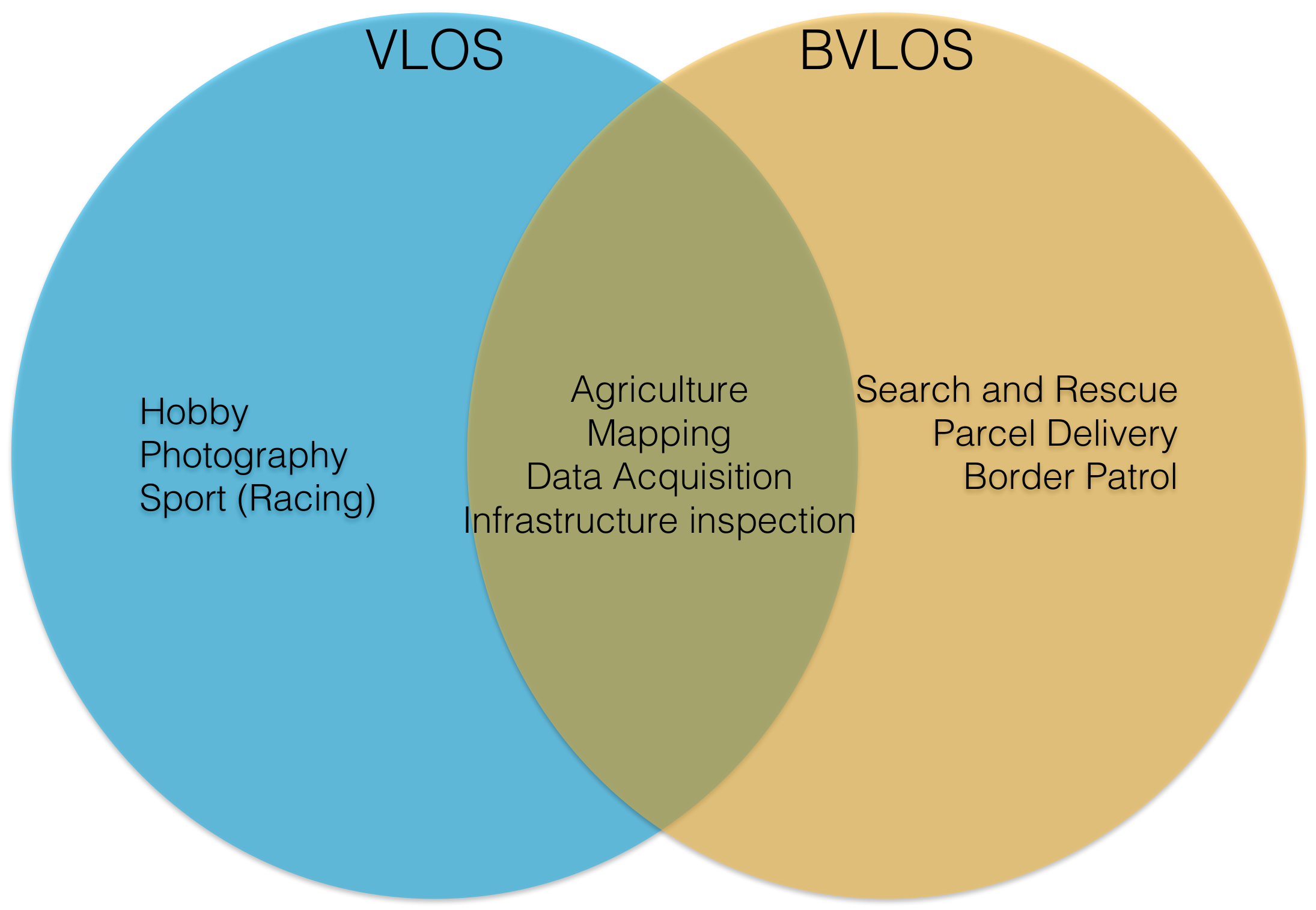
- Infrastructure Inspection can be conducted in two modalities, local (VLOS) or remote (BVLOS). Local inspections are intended to identify issues on the spot, in addition to recording data for further analysis. These operations are mostly flown in manual mode (pilot in control at all times, HI low ) and some automation might exist in the sensors used to acquire data or flight control. The environment and mission carry a degree of complexity mainly due to the fact that the unmanned aircraft will be flying close to a structure that might be functioning (power pole, tower, bridge, factory chimney, etc.) leading to low-medium EC and MC . A remote inspection involves mainly data acquisition in large and remote areas. (note: it is unclear the benefits of UAS for inspection in urban areas over current methods, due to the strict regulatory frameworks currently in place). EC and MC can be relatively high () due to the lack of pilot visual contact with the unmanned aircraft and the precision requirements on the guidance and navigation, path planning, sense-and-avoid, emergency procedures, etc. Therefore, in a remote modality we propose the following configuration: high level tasks such as 1–11, 18 and 21, low level tasks common to most UAS such as 13–17 and mission safety tasks such as 20 (Table 1). In a local modality, we propose the following configuration, energy management (4), storage management (9), low level tasks such as 13–17 and safety tasks such as obstacle avoidance (20) (Table 1).
- Precision agriculture applications typically have strict requirements on data accuracy, timing, overlap and resolution, amongst others. Furthermore, these requirements impose additional constraints on the flight pattern (navigation and guidance tasks) performed by the UAS. If we assume a typical farm with an extended area and relatively free airspace, then EC and MC can be both considered medium. However, HI will be high, in most cases, due to the precise flight patterns needed to acquire accurate data. There might be cases in which manual flight is permissible (from the data requirements point of view) which leads to low HI. We assume this application is conducted within VLOS and the main sensor for data collection is electro-optical, leading to the following proposed task configuration for precise and safe navigation such as 3–6, storage management (9), low level tasks such as 13–17 and camera specific tasks (18) (See Table 1).
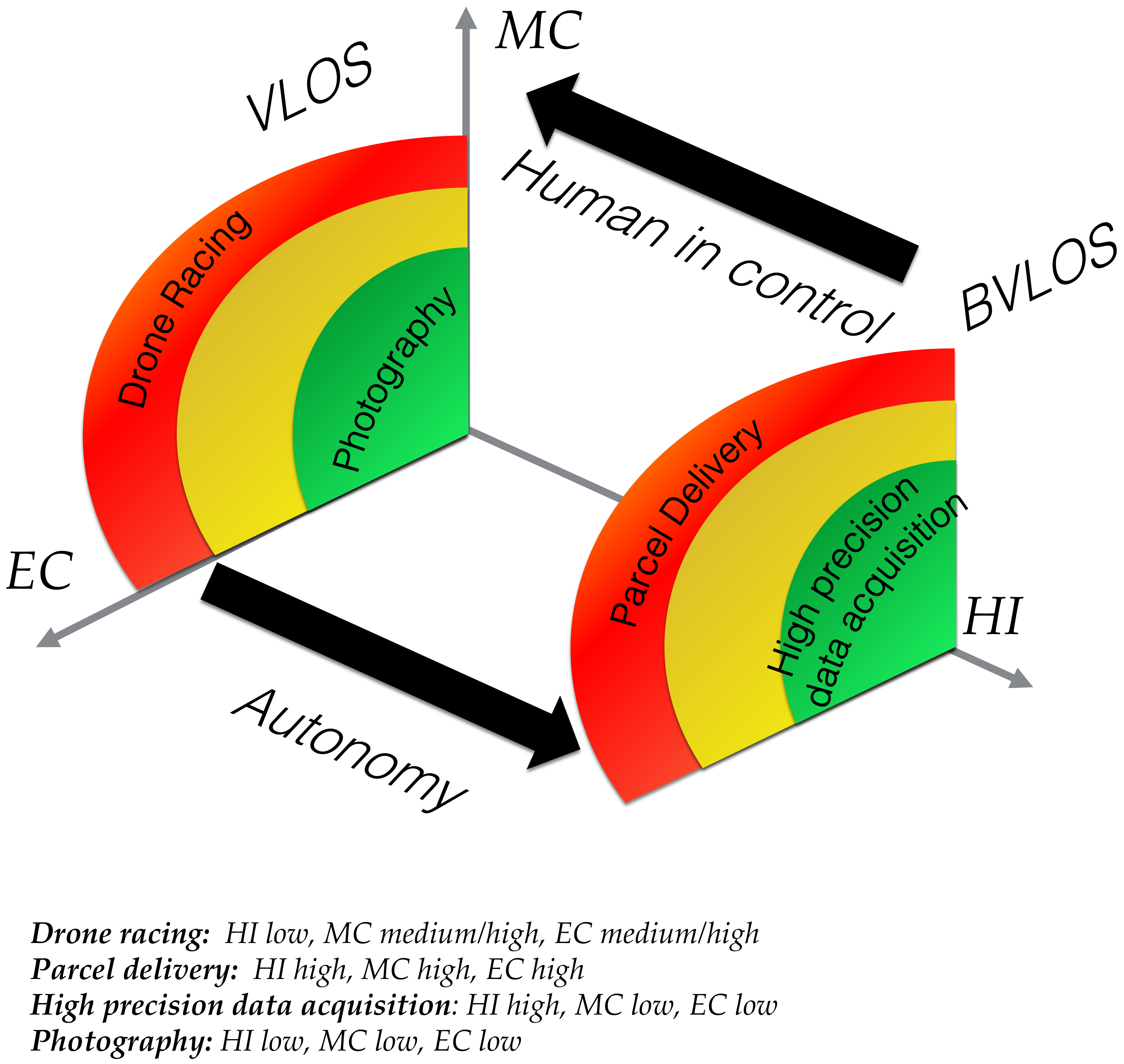
- Parcel delivery involves the transport of packages, food or other goods. There have been trials demonstrating the feasibility of this application in rural and suburban areas (low-medium MC and EC), and in close proximity to the base [31]. However, extending this application to a wider area (wider population) using more UAS simultaneously will likely require more onboard automation and support systems than currently in place. Systems such as air traffic management, collision and obstacle avoidance, decision making, etc. will now be required, which in turn will lead to more onboard autonomy (HI high). In our case study (Section 5), we assume a more generalised application in which HI is high, EC and MC are medium-high. Therefore, we propose a similar configuration to the remote inspection task, except for the need to run a specific task to land the unmanned aircraft at the delivery address (see proposed approach [31]). Assuming an electro-optical sensor might be used to the detect the landing site, we propose the following tasks 1–11, 13–17, 20–21 and camera used for landing (18) (See Table 1).
- Aerial photography is a common VLOS application in which cameras (still or video) are used to capture the scene. This application is typically conducted by highly skilled pilots (low HI) flying the UAS close to the movie scene (filmmaking), landscapes or man-made structures. Some automation might exist in the onboard cameras or gimbal but not enough to require a highly autonomous UAS. EC and MC are also relatively low due to simplicity of the overall task. Some might argue that the right positioning of the unmanned aircraft is critical to capture the best media possible, which in most cases it is true, however currently this requirement is handled entirely by the pilot and feedback through the video link. In this case, we propose the following configuration energy (4) and storage management (9), assuming an autopilot is used for UAS stabilisation, camera positioning and augmented flying then tasks 13–15 and 17 will be present, if a gimbal is used to track objects or fix the scene view independent of aircraft pose, then task 18 will be present (See Table 1).
- Drone racing is a relatively novel application of UAS. It consists of small multi-rotors equipped with controller boards for high speed precise and agile flight, and cameras to enable first-person-view (FPV) piloting. Almost all multi-rotors used in drone races are flown manually using FPV (low HI). The environment consist of several obstacles designed for high difficulty leading to high EC. The mission is however to complete the course through several checkpoints at high speed in a minimum time, therefore we assume a relatively straight-forward mission (low MC). The proposed configuration tasks will include energy management (4) and low level tasks such as 13–17 to enable unassisted rate mode [90]. Additionally, we can assume FPV and video recording fall under the category of application specific camera tasks (18) (See Table 1).
- Search and rescue using UAS is intended to aid and support search efforts in many situations for a fraction of the cost in terms of risk and resources. This application is considered very similar to remote infrastructure inspection (tasks 1–11, 13–17, 20–21), except for the addition of a camera task (18) to identify and localise objects or humans in the camera field of view. Environment and mission are considered high due to the coordination required (high MC) with other rescue systems that might be flying simultaneously (high EC). Human independence requirement is also high due to BVLOS operation modality (See Table 1).
Impact on Embedded Processing
5. Case Study: Parcel Delivery
5.1. Parcel Delivery
5.2. Assessing Task Computational Resources Requirements
6. Addressing the Computational Gap for High Levels of Autonomy
6.1. Embedded Computing Requirements
6.1.1. Computation Load
6.1.2. Heterogeneity
6.1.3. Memory Resources
6.1.4. Power Consumption
6.2. Architecture Requirements and Proposal
6.2.1. Architecture Model
6.2.2. Towards Hybrid Reconfigurable Systems
6.3. Impact on UAS Design Methodology and Opportunities
Towards Service Oriented Architectures (SOA) for Flexible and Adaptive Unmanned Aircraft Embedded Systems
7. Conclusions
Author Contributions
Funding
Institutional Review Board Statement
Informed Consent Statement
Data Availability Statement
Acknowledgments
Conflicts of Interest
References
- Jenkins, D.; Vasigh, B. The Economic Impact Of Unmanned Aircraft Systems Integration In the United States; Technical Report; Association for Unmanned Vehicle Systems International: Washington, DC, USA, 2013. [Google Scholar]
- ICAO. International Civil Aviation Organization (ICAO). Available online: https://www.icao.int/Pages/default.aspx (accessed on 29 January 2021).
- ICAO. Unmanned Aircraft Unmanned Aircraft Systems (UAS); Technical Report Circular 328 AN/190; International Civil Aviation Organization (ICAO): Montreal, QC, Canada, 2011. [Google Scholar]
- Huang, H.E. Autonomy Levels for Unmanned Systems Framework, Volume I: Terminology; NIST Special Publication 1011-I-2.0 Version 2.0; National Institute of Standards and Technology: Gaithersburg, MD, USA, 2008. [Google Scholar]
- Sheridan, T.; Verplank, W. Human and Computer Control of Undersea Teleoperators; Man-Machine Systems Laboratory, Massachusetts Institute of Technology: Cambridge, MA, USA, 1978. [Google Scholar]
- Parasuraman, R.; Sheridan, T.B.; Wickens, C.D. A model for types and levels of human interaction with au- tomation. IEEE Trans. Syst. Man Cybern. 2000, 30, 286–297. [Google Scholar] [CrossRef] [Green Version]
- Huang, H.M.; Messina, E.; Albus, J. Autonomy Levels for Unmanned Systems (ALFUS) Framework, Volume II: Framework Models; Version 1.0 NIST Special Publication 1011-II-1.0; NIST: Gaithersburg, MD, USA, 2007. [Google Scholar]
- Sholes, E. Evolution of a UAV Autonomy Classification Taxonomy. In Proceedings of the 2007 IEEE Aerospace Conference, Big Sky, MT, USA, 3–10 March 2007; pp. 1–16. [Google Scholar] [CrossRef]
- Clough, B. Metrics, schmetrics! how the heck do you determine a uav’s autonomy anyway. In Proceedings of the AIAA 1st Technical Conference and Workshop on Unmanned Aerospace Vehicles Systems, Technologies and Operations (2002), Portsmouth, VI, USA, 20–23 May 2002; pp. 313–319. [Google Scholar]
- Huang, H.M.; Messina, E.; Jacoff, A. Performance Measures Framework for Unmanned Systems (PerMFUS): Initial Perspective. In Proceedings of the 9th Workshop on Performance Metrics for Intelligent Systems, Baltimore, MD, USA, 21–23 September 2009; pp. 65–72. [Google Scholar] [CrossRef]
- Kendoul, F. Survey of advances in guidance, navigation, and control of unmanned rotorcraft systems. J. Field Robot. 2012, 29, 315–378. [Google Scholar] [CrossRef]
- Taylor, R.M. Capability, Cognition and Autonomoy. In Proceedings of the RTO HFM Symposium on the Role of Humans in Intelligent and Automated Systems, Warsaw, Poland, 7–9 October 2002. [Google Scholar]
- Valavanis, K.; Vachtsevanos, G.J. (Eds.) Handbook of Unmanned Aerial Vehicles; Springer: Dordrecht, The Netherlands, 2015. [Google Scholar]
- Nonami, K.; Kartidjo, M.; Yoon, K.J.; Budiyono, A. (Eds.) Towards a Unified Framework for UAS Autonomy and Technology Readiness Assessment (ATRA). In Autonomous Control Systems and Vehicles: Intelligent Unmanned Systems; Springer: Tokyo, Japan, 2013; pp. 55–71. [Google Scholar] [CrossRef]
- Cummings, M.; Bruni, S.; MItchell, S.M.P. Automation architecture for single operator, multiple UAV command and control. Int. C2 J. 2007, 1, 1–24. [Google Scholar]
- Proud, R.W.; Hart, J.J.; Mrozinski, R.B. Methods for Determining the Level of Autonomy to Design into a Human Spaceflight Vehicle: A Function Specific Approach. In PerMIS’03, Performance Metrics for Intelligent Systems; National Aeronautics and Space Administration Houston TX Lyndon B Johnson Space Center: Gaithersburg, MD, USA, 2003. [Google Scholar]
- Huang, H.M.; Pavek, K.; Novak, B.; Albus, J.; Messina, E. A framework of autonomy levels for unmanned systems. In Proceedings of the AUVSI’s Unmanned Systems North America, Baltimore, MD, USA, 28–30 June 2005; pp. 1–9. [Google Scholar]
- Doherty, P.; Rudol, P. A UAV Search and Rescue Scenario with Human Body Detection and Geolocalization. In AI 2007: Advances in Artificial Intelligence; Orgun, M., Thornton, J., Eds.; Springer: Berlin/Heidelberg, Germany, 2007; Volume 4830, pp. 1–13. [Google Scholar] [CrossRef]
- CASA. Civil Aviation Safety Regulations 1998 (CASR) Part 101—Unmanned Aircraft and Rockets. 2020. Available online: https://www.casa.gov.au/drones/documents-and-forms (accessed on 29 January 2021).
- FAA. 14 CFR Part 107. Part 107—Small Unmanned Aircraft Systems. 2021. Available online: https://www.ecfr.gov/ (accessed on 29 January 2021).
- Angelov, P. (Ed.) Sense and Avoid in UAS: Research and Application; Wiley: Hoboken, NJ, USA, 2012. [Google Scholar]
- Bruggemann, T.S.; Ford, J.J. Automated aerial inspection guidance with improved turn planning. In Proceedings of the Australian Control Conference (AUCC 2013), Fremantle, WA, Australia, 4–5 November 2013; pp. 282–288. [Google Scholar] [CrossRef]
- Bruggemann, T.S.; Ford, J.J.; Walker, R.A. Control of Aircraft for Inspection of Linear Infrastructure. IEEE Trans. Control Syst. Technol. 2011, 19, 1397–1409. [Google Scholar] [CrossRef] [Green Version]
- Merz, T.; Kendoul, F. Dependable Low-altitude Obstacle Avoidance for Robotic Helicopters Operating in Rural Areas. J. Field Robot. 2013, 30, 439–471. [Google Scholar] [CrossRef]
- Pixhawk4. 2018. Available online: https://github.com/PX4/Hardware/blob/master/FMUv5/Pixhawk4-Data-Sheet.pdf (accessed on 29 January 2021).
- Warren, M.; Mejias, L.; Kok, J.; Yang, X.; Gonzalez, F.; Upcroft, B. An Automated Emergency Landing System for Fixed-Wing Aircraft: Planning and Control. J. Field Robot. 2015, 32, 1114–1140. [Google Scholar] [CrossRef] [Green Version]
- Menon, P.; Ohlmeyer, E. Integrated design of agile missile guidance and autopilot systems. Control Eng. Pract. 2001, 9, 1095–1106. [Google Scholar] [CrossRef]
- Murugan, D.; Garg, A.; Singh, D. Development of an Adaptive Approach for Precision Agriculture Monitoring with Drone and Satellite Data. IEEE J. Sel. Top. Appl. Earth Obs. Remote Sens. 2017, 10, 5322–5328. [Google Scholar] [CrossRef]
- Merz, T.; Kendoul, F. Beyond Visual Range Obstacle Avoidance and Infrastructure Inspection by an Autonomous Helicopter. In Proceedings of the 2011 IEEE/RSJ International Conference on Intelligent Robots and Systems, San Francisco, CA, USA, 25–30 September 2011; pp. 4953–4960. [Google Scholar]
- Pak, M.; Preston, R.; Groccia, C.; Taylor, J. Conventional and advanced borehole investigation methods for inaccessible underground voids. In Proceedings of the First International Conference on Underground Mining Technology, Sudbury, ON, Canada, 11–13 October 2017; pp. 457–465. [Google Scholar]
- Amazon. Amazon Prime Air. 2017. Available online: https://en.wikipedia.org/wiki/Amazon_Prime_Air (accessed on 29 January 2021).
- Geng, L.; Zhang, Y.F.; Wang, J.J.; Fuh, J.Y.H.; Teo, S.H. Mission planning of autonomous UAVs for urban surveillance with evolutionary algorithms. In Proceedings of the 2013 10th IEEE International Conference on Control and Automation (ICCA), Hangzhou, China, 12–14 June 2013; pp. 828–833. [Google Scholar] [CrossRef]
- Schumann, J.M.; Rozier, K.Y.; Reinbacher, T.; Mengshoel, O.J.; Mbaya, T.; Ippolito, C. Towards real-time, on-board, hardware-supported sensor and software health management for unmanned aerial systems. Int. J. Progn. Health Manag. 2015, 6, 1–27. [Google Scholar]
- Hireche, C.; Dezan, C.; Diguet, J.; Mejias, L. BFM: A Scalable and Resource-Aware Method for Adaptive Mission Planning of UAVs. In Proceedings of the 2018 IEEE International Conference on Robotics and Automation (ICRA), Brisbane, QLD, Australia, 21–25 May 2018; pp. 6702–6707. [Google Scholar] [CrossRef] [Green Version]
- Kröhnert, M.; Grimm, R.; Vahrenkamp, N.; Asfour, T. Resource-aware motion planning. In Proceedings of the 2016 IEEE International Conference on Robotics and Automation (ICRA), Stockholm, Sweden, 16–21 May 2016; pp. 32–39. [Google Scholar] [CrossRef]
- Lai, J.S.; Mejias, L.; Ford, J.J. Airborne vision-based collision-detection system. J. Field Robot. 2011, 28, 137–157. [Google Scholar] [CrossRef] [Green Version]
- Kopardekar, P. Unmanned Aerial System (UAS) Traffic Management (UTM): Enabling Low-Altitude Airspace and UAS Operations; Technical Report NASA Technical Memorandum, NASA/TM-2014-218299; NASA: Hampton, VA, USA, 2014. [Google Scholar]
- Codetta-Raiteri, D.; Portinale, L. Dynamic Bayesian Networks for Fault Detection, Identification, and Recovery in Autonomous Spacecraft. IEEE Trans. Syst. Man Cybern. Syst. 2015, 45, 13–24. [Google Scholar] [CrossRef]
- Cork, L. Aircraft Dynamic Navigation for Unmanned Aerial Vehicles. Ph.D. Thesis, Queensland University of Technology, Brisbane, Australia, 2014. [Google Scholar]
- Boskovic, J.; Prasanth, R.; Mehra, R. A multilayer control architecture for unmanned aerial vehicles. In Proceedings of the American Control Conference, Anchorage, AK, USA, 8–10 May 2002; Volume 3, pp. 1825–1830. [Google Scholar] [CrossRef]
- Schmid, K.; Lutz, P.; Tomić, T.; Mair, E.; Hirschmüller, H. Autonomous Vision-based Micro Air Vehicle for Indoor and Outdoor Navigation. J. Field Robot. 2014, 31, 537–570. [Google Scholar] [CrossRef]
- Faessler, M.; Fontana, F.; Forster, C.; Mueggler, E.; Pizzoli, M.; Scaramuzza, D. Autonomous, Vision-based Flight and Live Dense 3D Mapping with a Quadrotor Micro Aerial Vehicle. J. Field Robot. 2016, 33, 431–450. [Google Scholar] [CrossRef]
- Matthies, L. Dynamic Stereo Vision; Cmu-cs-89-195; Computer Science Department, Carnegie Mellon University: Pittsburgh, PA, USA, 1989. [Google Scholar]
- Maimone, M.; Cheng, Y.; Matthies, L. Two years of Visual Odometry on the Mars Exploration Rovers. J. Field Robot. 2007, 24, 169–186. [Google Scholar] [CrossRef] [Green Version]
- Artieda, J.; Sebastian, J.M.; Campoy, P.; Correa, J.F.; Mondragón, I.F.; Martínez, C.; Olivares, M. Visual 3-D SLAM from UAVs. J. Intell. Robot. Syst. 2009, 55, 299. [Google Scholar] [CrossRef]
- Wang, C.; Wang, T.; Liang, J.; Chen, Y.; Zhang, Y.; Wang, C. Monocular visual SLAM for small UAVs in GPS-denied environments. In Proceedings of the 2012 IEEE International Conference on Robotics and Biomimetics (ROBIO), Guangzhou, China, 11–14 December 2012; pp. 896–901. [Google Scholar] [CrossRef]
- Weiss, S.; Achtelik, M.W.; Lynen, S.; Achtelik, M.C.; Kneip, L.; Chli, M.; Siegwart, R. Monocular Vision for Long-term Micro Aerial Vehicle State Estimation: A Compendium. J. Field Robot. 2013, 30, 803–831. [Google Scholar] [CrossRef]
- Barry, A.J.; Tedrake, R. Pushbroom stereo for high-speed navigation in cluttered environments. In Proceedings of the 2015 IEEE International Conference on Robotics and Automation (ICRA), Seattle, WA, USA, 26–30 May 2015; pp. 3046–3052. [Google Scholar] [CrossRef] [Green Version]
- Greisen, P.; Heinzle, S.; Gross, M.; Burg, A.P. An FPGA-based processing pipeline for high-definition stereo video. EURASIP J. Image Video Process. 2011, 2011, 18. [Google Scholar] [CrossRef] [Green Version]
- Häming, K.; Peters, G. The structure-from-motion reconstruction pipeline—A survey with focus on short image sequences. Kybernetika 2010, 46, 926–937. [Google Scholar]
- Dellaert, F.; Seitz, S.M.; Thorpe, C.E.; Thrun, S. Structure from motion without correspondence. In Proceedings of the IEEE Conference on Computer Vision and Pattern Recognition CVPR 2000 (Cat. No.PR00662), Hilton Head Island, SC, USA, 15 June 2000; Volume 2, pp. 557–564. [Google Scholar] [CrossRef]
- Strydom, R.; Denuelle, A.; Srinivasan, M.V. Bio-Inspired Principles Applied to the Guidance, Navigation and Control of UAS. Aerospace 2016, 3, 21. [Google Scholar] [CrossRef] [Green Version]
- Kendoul, F.; Fantoni, I.; Nonami, K. Optic flow-based vision system for autonomous 3D localization and control of small aerial vehicles. Robot. Auton. Syst. 2009, 57, 591–602. [Google Scholar] [CrossRef] [Green Version]
- Ruffier, F.; Viollet, S.; Amic, S.; Franceschini, N. Bio-inspired optical flow circuits for the visual guidance of micro air vehicles. In Proceedings of the 2003 International Symposium on Circuits and Systems, ISCAS ’03, Bangkok, Thailand, 25–28 May 2003. [Google Scholar]
- Hardy, J.; Strader, J.; Gross, J.N.; Gu, Y.; Keck, M.; Douglas, J.; Taylor, C.N. Unmanned aerial vehicle relative navigation in GPS denied environments. In Proceedings of the 2016 IEEE/ION Position, Location and Navigation Symposium (PLANS), Savannah, GA, USA, 11–14 April 2016; pp. 344–352. [Google Scholar]
- Johnson, E.N.; Calise, A.J.; Watanabe, Y.; Ha, J.; Neidhoefer, J.C. Real-time vision-based relative aircraft navigation. J. Aerosp. Comput. Inf. Commun. 2007, 4, 707–738. [Google Scholar] [CrossRef] [Green Version]
- Sebbane, Y.B. Smart Autonomous Aircraft: Flight Control and Planning for UAV; CRC Press: Boca Raton, FL, USA, 2015. [Google Scholar]
- Kok, J.; Gonzalez, L.F.; Kelson, N. FPGA Implementation of an Evolutionary Algorithm for Autonomous Unmanned Aerial Vehicle On-Board Path Planning. IEEE Trans. Evol. Comput. 2013, 17, 272–281. [Google Scholar] [CrossRef] [Green Version]
- Kider, J.T.; Henderson, M.; Likhachev, M.; Safonova, A. High-dimensional planning on the GPU. In Proceedings of the 2010 IEEE International Conference on Robotics and Automation, Anchorage, AK, USA, 3–7 May 2010; pp. 2515–2522. [Google Scholar]
- Kanellakis, C.; Nikolakopoulos, G. Survey on Computer Vision for UAVs: Current Developments and Trends. J. Intell. Robot. Syst. 2017, 87, 141–168. [Google Scholar] [CrossRef] [Green Version]
- Gageik, N.; Benz, P.; Montenegro, S. Obstacle Detection and Collision Avoidance for a UAV With Complementary Low-Cost Sensors. IEEE Access 2015, 3, 599–609. [Google Scholar] [CrossRef]
- Nageli, T. Intelligent Drone Cinematography. Ph.D. Thesis, ETH Zurich, Zürich, Switzerland, 2018. [Google Scholar] [CrossRef]
- Hao, J.; Zhou, Y.; Zhang, G.; Lv, Q.; Wu, Q. A Review of Target Tracking Algorithm Based on UAV. In Proceedings of the 2018 IEEE International Conference on Cyborg and Bionic Systems (CBS), Shenzhen, China, 25–27 October 2018; pp. 328–333. [Google Scholar] [CrossRef]
- Duffy, J.P.; Shutler, J.D.; Witt, M.J.; DeBell, L.; Anderson, K. Tracking Fine-Scale Structural Changes in Coastal Dune Morphology Using Kite Aerial Photography and Uncertainty-Assessed Structure-from-Motion Photogrammetry. Remote Sens. 2018, 10, 1494. [Google Scholar] [CrossRef] [Green Version]
- Chang, J.; Nepal, M.P. Using Drones for Precision Agriculture. ILEARN Teach. Resour. 2019, 2, 38–42. [Google Scholar]
- Kalal, Z.; Mikolajczyk, K.; Matas, J. Tracking-learning-detection. Pattern Anal. Mach. Intell. 2012, 34, 1409–1422. [Google Scholar] [CrossRef] [PubMed] [Green Version]
- Xiao, C.; Wang, L.; Zhu, M.; Wang, W. A Resource-efficient Multimedia Encryption Scheme for Embedded Video Sensing System Based on Unmanned Aircraft. J. Netw. Comput. Appl. 2016, 59, 117–125. [Google Scholar] [CrossRef] [Green Version]
- Villa, T.F.; Gonzalez, F.; Miljievic, B.; Ristovski, Z.D.; Morawska, L. An Overview of Small Unmanned Aerial Vehicles for Air Quality Measurements: Present Applications and Future Prospectives. Sensors 2016, 16, 1072. [Google Scholar] [CrossRef] [Green Version]
- Mcfadyen, A.; Mejias, L. A Survey of autonomous vision-based See and Avoid for Unmanned Aircraft Systems. Prog. Aerosp. Sci. 2016, 80, 1–17. [Google Scholar] [CrossRef]
- Maybeck, P. Multiple model adaptive algorithms for detecting and compensating sensor and actuator/surface failures in aircraft flight control systems. Int. J. Robust Nonlinear Control. 1999, 9, 1051–1070. [Google Scholar] [CrossRef]
- Eide, F.; Maybeck, P. An MMAE failure detection system for the F-16. IEEE Trans. Aerosp. Electron. Syst. 1995, 32, 1125–1136. [Google Scholar] [CrossRef] [Green Version]
- Meskin, N.; Naderi, E.; Khorasani, K. Multiple model-based approach for fault diagnosis of jet engines. IEEE Trans. Control Syst. Technol. 2013, 21, 254–262. [Google Scholar] [CrossRef]
- Yang, X.; Warren, M.; Arain, B.; Upcroft, B.; Gonzalez, F.; Mejias, L. A UKF-based Estimation Strategy for Actuator Fault Detection of UASs. In Proceedings of the 2013 International Conference on Unmanned Aircraft Systems (ICUAS), Atlanta, GA, USA, 28–31 May 2013; pp. 516–525. [Google Scholar] [CrossRef] [Green Version]
- Valenti, M.; Bethke, B.; Fiore, G.; How, J.; Feron, E. Indoor Multi-Vehicle Flight Testbed for Fault Detection, Isolation, and Recovery. In Proceedings of the AIAA Guidance, Navigation, and Control Conference and Exhibit, Keystone, CO, USA, 21–24 August 2006. [Google Scholar] [CrossRef] [Green Version]
- Drozeski, G.R. A Fault-Tolerant Control Architecture for Unmanned Aerial Vehicles. Ph.D. Thesis, Electrical and Computer Engineering, Georgia Institute of Technology, Atlanta, GA, USA, 2005. [Google Scholar]
- Mejias, L.; Greer, D. Flight Guardian: A common avionics architecture for collision avoidance and safe emergency landing for unmanned aerial systems. In Proceedings of the 2012 IEEE/AIAA 31st Digital Avionics Systems Conference (DASC), Williamsburg, VA, USA, 14–18 October 2012; pp. 8A3-1–8A3-10. [Google Scholar] [CrossRef]
- Rios, J.; Mulfinger, D.; Homola, J.; Venkatesan, P. NASA UAS traffic management national campaign: Operations across Six UAS Test Sites. In Proceedings of the 2016 IEEE/AIAA 35th Digital Avionics Systems Conference (DASC), Sacramento, CA, USA, 25–29 September 2016; pp. 1–6. [Google Scholar] [CrossRef] [Green Version]
- Tomasello, F.; Ducci, M. Research for Tran Committee-Safe Integration of Drones into Airspace; Technical Report; European Parliament, Policy Department B: Structural and Cohesion Policies: Brussels, Belgium, 2016. [Google Scholar]
- Mcfadyen, A.; Martin, T. Erminal airspace modelling for unmanned aircraft systems integration. In Proceedings of the 2016 International Conference on Unmanned Aircraft Systems, Arlington, VA, USA, 7–10 June 2016. [Google Scholar]
- Johnson, S.B.; Gormley, T.J.; Kessler, S.S.; Mott, C.D.; Patterson-Hine, A.; Reichard, K.M.; Scandura, P.A. System Health Management: With Aerospace Applications; John Wiley & Sons, Ltd.: Hoboken, NJ, USA, 2011. [Google Scholar]
- Tan, Z.J.; Zhang, Z.; Shi, Y.B. The Overview of the Health Monitoring Management System. Phys. Procedia 2012, 33, 1323–1329. [Google Scholar] [CrossRef] [Green Version]
- Smith, M.; Sulcs, P.; Walthall, R.; Mosher, M.; Kacprzynski, G. Design and Implementation of Aircraft System Health Management (ASHM) Utilizing Existing Data Feeds; Technical Report SAE Technical Paper 2015-01-2587; SAE: Chicago, IL, USA, 2015. [Google Scholar] [CrossRef]
- Valenti, M.; Bethke, B.; How, J.P.; de Farias, D.P.; Vian, J. Embedding Health Management into Mission Tasking for UAV Teams. In Proceedings of the 2007 American Control Conference, New York, NY, USA, 11–13 July 2007; pp. 5777–5783. [Google Scholar] [CrossRef] [Green Version]
- Schumann, J.; Mbaya, T.; Mengshoel, O. Bayesian software health management for aircraft guidance, navigation, and control. In Proceedings of the Annual Conference of the Prognostics and Health Management Society, Montreal, QC, Canada, 25–29 September 2011; Volume 2. [Google Scholar]
- Jing, D.; Haifeng, W. System health management for Unmanned Aerial Vehicle: Conception, state-of-art, framework and challenge. In Proceedings of the 2013 IEEE 11th International Conference on Electronic Measurement Instruments, Harbin, China, 16–19 August 2013; Volume 2, pp. 859–863. [Google Scholar] [CrossRef]
- Lee, B.; Kwon, S.; Park, P.; Kim, K. Active power management system for an unmanned aerial vehicle powered by solar cells, a fuel cell, and batteries. IEEE Trans. Aerosp. Electron. Syst. 2014, 50, 3167–3177. [Google Scholar] [CrossRef]
- Hong, C.; Varghese, B. Resource Management in Fog/Edge Computing: A Survey. ACM Comput. Surv. 2019, 52, 1–37. [Google Scholar]
- Fujimura, K. Path planning with multiple objectives. IEEE Robot. Autom. Mag. 1996, 3, 33–38. [Google Scholar] [CrossRef] [Green Version]
- Da Silva Arantes, J.; da Silva Arantes, M.; Toledo, C.F.M.; Júnior, O.T.; Williams, B.C. An embedded system architecture based on genetic algorithms for mission and safety planning with UAV. In Proceedings of the Genetic and Evolutionary Computation Conference (GECCO), Berlin, Germany, 15–19 July 2017; pp. 1049–1056. [Google Scholar]
- DRL. Drone Racing League. 2017. Available online: https://thedroneracingleague.com (accessed on 29 January 2021).
- Bonasso, R.P.; Firby, R.J.; Gat, E.; Kortenkamp, D.; Miller, D.P.; Slack, M.G. Experiences with an architecture for intelligent, reactive agents. J. Exp. Theor. Artif. Intell. 1997, 9, 237–256. [Google Scholar] [CrossRef]
- Gohl, P.; Honegger, D.; Omari, S.; Achtelik, M.; Pollefeys, M.; Siegwart, R. Omnidirectional visual obstacle detection using embedded FPGA. In Proceedings of the 2015 IEEE/RSJ International Conference on Intelligent Robots and Systems (IROS), Hamburg, Germany, 28 September–2 October 2015; pp. 3938–3943. [Google Scholar] [CrossRef]
- Russo, J.; Amduka, M.; Pendersen, K.; Lethin, R.; Springer, J.; Manohar, R.; Melhem, R. Enabling Cognitive Architectures for UAV Mission Planning. In Proceedings of the High Performance Embedded Computing Workshop (HPEC), Lexington, MA, USA, 19–21 September 2006. [Google Scholar]
- Boniol, F.; Wiels, V. Towards Modular and Certified Avionics for UAV. J. Aerosp. Lab. 2014, AL08-02. [Google Scholar] [CrossRef]
- Heutger, M.; Kuckelhaus, M. Unmanned aerial vehicles in logistics. In A DHL Perspective on Implications and Use Cases for the Logistics Industry; Technical Report; DHL Customer Solutions & Innovation: Troisdorf, Germany, 2014. [Google Scholar]
- Zarandy, A.; Zsedrovits, T.; Nagy, Z.; Kiss, A.; Roska, T. Visual sense-and-avoid system for UAVs. In Proceedings of the 13th International Workshop on Cellular Nanoscale Networks and their Applications, Turin, Italy, 29–31 August 2012; pp. 1–5. [Google Scholar] [CrossRef]
- Flynn, M. Some Computer Organizations and Their Effectiveness. IEEE Trans. Comput. 1972, C-21, 948–960. [Google Scholar] [CrossRef]
- Gonzalez-Velez, H.; Leyton, M. A survey of algorithmic skeleton frameworks: High-level structured parallel programming enablers. Softw. Pract. Exp. 2010, 40, 1135–1160. [Google Scholar] [CrossRef]
- Asanovic, K.; Bodik, R.; Catanzaro, B.C.; Gebis, J.J.; Husbands, P.; Keutzer, K.; Patterson, D.A.; Plishker, W.L.; Shalf, J.; Williams, S.W.; et al. The Landscape of Parallel Computing Research: A View from Berkeley; Technical Report UCB/EECS-2006-183; EECS Department, University of California: Berkeley, CA, USA, 2006. [Google Scholar]
- Le Moullec, Y.; Amor, N.; Diguet, J.P.; Abid, M.; Philippe, J.L. Multi-granularity metrics for the era of strongly personalized SOCs. In Proceedings of the Design, Automation and Test in Europe Conference and Exhibition, Munich, Germany, 7 March 2003; pp. 674–679. [Google Scholar] [CrossRef]
- Angelopoulou, M.E.; Bouganis, C.S. Vision-Based Egomotion Estimation on FPGA for Unmanned Aerial Vehicle Navigation. IEEE Trans. Circuits Syst. Video Technol. 2014, 24, 1070–1083. [Google Scholar] [CrossRef]
- Mur-Artal, R.; Montiel, J.M.M.; Tards, J.D. ORB-SLAM: A Versatile and Accurate Monocular SLAM System. IEEE Trans. Robot. 2015, 31, 1147–1163. [Google Scholar] [CrossRef] [Green Version]
- Wu, P.P.; Campbell, D.A.; Merz, T. Multi-objective four-dimensional vehicle motion planning in large dynamic environments. IEEE Trans. Syst. Man Cybern. Part B Cybern. 2011, 41, 621–634. [Google Scholar] [CrossRef] [PubMed] [Green Version]
- Krommydas, K.; Feng, W.-C.; Owaida, M.; Antonopoulos, C.D.; Bellas, N. On the characterization of OpenCL dwarfs on fixed and reconfigurable platforms. In Proceedings of the 2014 IEEE 25th International Conference on Application-Specific Systems, Architectures and Processors, Zurich, Switzerland, 18–20 June 2014; pp. 153–160. [Google Scholar] [CrossRef]
- Mejias, L.; Fitzgerald, D. A multi-layered approach for site detection in UAS emergency landing scenarios using geometry-based image segmentation. In Proceedings of the 2013 International Conference on Unmanned Aircraft Systems (ICUAS), Atlanta, GA, USA, 28–31 May 2013; pp. 366–372. [Google Scholar] [CrossRef] [Green Version]
- Liu, Y.; Yang, J.; Liu, M. Recognition of QR Code with mobile phones. In Proceedings of the 2008 Chinese Control and Decision Conference, Yantai, China, 2–4 July 2008; pp. 203–206. [Google Scholar]
- Han, S.; Shen, W.; Liu, Z. Deep Drone: Object Detection and Tracking for Smart Drones on Embedded System. 2016. Available online: https://web.stanford.edu/class/cs231a/prev_projects_2016/deep-drone-object__2_.pdf (accessed on 29 January 2021).
- Inaba, M.; Corke, P. (Eds.) Environment. In Robotics Research: The 16th International Symposium ISRR; Springer International Publishing: Cham, Swizterland, 2016; pp. 611–629. [Google Scholar] [CrossRef]
- Motamedi, M.; Gysel, P.; Akella, V.; Ghiasi, S. Design space exploration of FPGA-based Deep Convolutional Neural Networks. In Proceedings of the 21st Asia and South Pacific Design Automation Conference (ASP-DAC), Tokyo, Japan, 25–28 January 2016; pp. 575–580. [Google Scholar] [CrossRef]
- Tmar, H.; Diguet, J.; Azzedine, A.; Abid, M.; Philippe, J. RTDT: A Static QoS Manager, RT Scheduling, HW/SW Partitioning CAD Tool. Microelectron. J. 2006, 37, 1208–1219. [Google Scholar] [CrossRef] [Green Version]
- Munir, A.; Gordon-Ross, A.; Lysecky, S.; Lysecky, R. Online Algorithms for Wireless Sensor Networks Dynamic Optimization. In Proceedings of the IEEE Consumer Communications and Networking Conference (CCNC), Las Vegas, NV, USA, 14–17 January 2012. [Google Scholar]
- Véstias, M.; Neto, H. Trends of CPU, GPU and FPGA for high-performance computing. In Proceedings of the 24th International Conference on Field Programmable Logic and Applications (FPL), Darmstadt, Germany, 23–25 September 2014. [Google Scholar] [CrossRef]
- Zhang, C.; Fang, Z.; Zhou, P.; Pan, P.; Cong, J. Caffeine: Towards uniformed representation and acceleration for deep convolutional neural networks. In Proceedings of the 2016 IEEE/ACM Int. Conf. on Computer-Aided Design (ICCAD), Santa Clara, CA, USA, 7–10 November 2016; pp. 1–8. [Google Scholar] [CrossRef]
- Martí, M.; Barekatain, A.; Shih, H.; Murray, S.; Matsuo, Y.; Prendinger, H. Situation Awareness for UAVs Using Deep Learning Techniques; SIG-AGI: Melbourne, Australia, 2017. [Google Scholar]
- Boreal-UAV-Datasheet. 2017. Available online: www.boreal-uas.com/wp-content/uploads/2016/09/BOREAL-v3.pdf (accessed on 29 January 2021).
- Top500 List. 2018. Available online: https://www.top500.org/lists (accessed on 29 January 2021).
- Li, H.; Fan, X.; Jiao, L.; Cao, W.; Zhou, X.; Wang, L. A high performance FPGA-based accelerator for large-scale convolutional neural networks. In Proceedings of the 26th International Conference on Field Programmable Logic and Applications (FPL), Lausanne, Switzerland, 29 August–2 September 2016. [Google Scholar] [CrossRef]
- Dridi, M.; Rubini, S.; Lallali, M.; Flórez, M.J.S.; Singhoff, F.; Diguet, J. Design and Multi-Abstraction-Level Evaluation of a NoC Router for Mixed-Criticality Real-Time Systems. ACM J. On. Emerg. Technol. Comput. (JETC) 2019, 15, 2:1–2:37. [Google Scholar] [CrossRef] [Green Version]
- Das, R.; Narayanasamy, S.; Satpathy, S.K.; Dreslinski, R.G. Catnap: Energy Proportional Multiple Network-on-chip. In Proceedings of the 40th Annual Int. Symp. on Computer Architecture (ISCA), New York, NY, USA, 23–27 June 2013; pp. 320–331. [Google Scholar] [CrossRef]
- Kapre, N.; Gray, J. Hoplite: Building austere overlay NoCs for FPGAs. In Proceedings of the 2015 25th International Conference on Field Programmable Logic and Applications (FPL), London, UK, 2–4 September 2015; pp. 1–8. [Google Scholar] [CrossRef]
- Aerotenna. OCPOC-Zynq. 2017. Available online: https://aerotenna.com/ocpoc-zynq/ (accessed on 29 January 2021).
- Xilinx. Versal: The First Adaptive Compute Acceleration Platform (ACAP). 2020. Available online: https://www.xilinx.com/support/documentation/white_papers/wp505-versal-acap.pdf (accessed on 29 January 2021).
- Hill, K.; Craciun, S.; George, A.; Lam, H. Comparative analysis of OpenCL vs. HDL with image-processing kernels on Stratix-V FPGA. In Proceedings of the IEEE 26th International Conference on Application-specific Systems, Architectures and Processors (ASAP), Toronto, ON, Canada, 27–29 July 2015. [Google Scholar] [CrossRef] [Green Version]
- Moréac, E.; Abdali, E.; Berry, F.; Heller, D.; Diguet, J.P. Hardware-in-the-loop simulation with dynamic partial FPGA reconfiguration applied to computer vision in ROS-based UAV. In Proceedings of the 31st International Workshop on Rapid System Prototyping (ESWeek/RSP), Hamburg, Germany, 24–25 September 2020. [Google Scholar]
- Hung, C.C.; Lin, C.H.; Teng, Y.J.; Chang, C.M.; Wu, Y.K. Study on mini UAV designs to payload requirements by airplane sizing methodology. In Proceedings of the AIAA Infotech@Aerospace 2010, Atlanta, GA, USA, 20–22 April 2010. [Google Scholar]
- Sadraey, M. A systems engineering approach to unmanned aerial vehicle design. In Proceedings of the 10th AIAA Aviation Technology, Integration and Operations (ATIO) Conference, Ft. Worth, TX, USA, 13–15 September 2010. [Google Scholar]
- Schumann, B.; Ferraro, M.; Surendra, A. Better design decisions through operational modelling during the early phases. J. Aerosp. Inf. Syst. 2014, 11, 195–210. [Google Scholar]
- Ilarslan, M.; Bayrakceken, M.; Arisoy, A. Avionics System Design of a mini VTOL UAV. In Proceedings of the 29th Digital Avionics Systems Conference, Salt Lake City, UT, USA, 3–7 October 2010. [Google Scholar] [CrossRef]
- Rodrigues, D.; de Melo Pires, R.; Marconato, E.A.; Areias, C.; Cunha, J.C.; Branco, K.R.L.J.C.; Vieira, M. Service-Oriented Architectures for a Flexible and Safe Use of Unmanned Aerial Vehicles. IEEE Intell. Transp. Syst. Mag. 2017, 9, 97–109. [Google Scholar] [CrossRef]
- Marconato, E.; Pigatto, D.; Castelo Branco, K. LARISSA: Layered Architecture Model for interconnections of systems in UAS. In Proceedings of the 2014 International Conference on Unmanned Aircraft Systems (ICUAS), Orlando, FL, USA, 27–30 May 2014. [Google Scholar]
- An, X.; Rutten, E.; Diguet, J.P.A.; Gamatié, A. Model-Based Design of Correct Controllers for Dynamically Reconfigurable Architectures. ACM Trans. Embed. Comput. Syst. 2016, 15, 1–27. [Google Scholar] [CrossRef] [Green Version]
- Gueye, S.M.K.; Rutten, E.; Diguet, J.P. Autonomic Management of Missions and Reconfigurations in FPGA-based Embedded System. In Proceedings of the 11th NASA/ESA Conf. on Adaptive Hardware and Systems (AHS), Essex, UK, 24–27 July 2017. [Google Scholar]


| Number | Task- |
|---|---|
| 1 | Sense and avoid |
| 2 | Emergency procedures |
| 3 | Fault detection and identification |
| 4 | Energy management |
| 5 | Path planning and trajectory tracking |
| 6 | Waypoint navigation |
| 7 | Decision making |
| 8 | Computational resources management |
| 9 | Storage management |
| 10 | Communication management |
| 11 | Airspace management |
| 12 | Vision-based navigation |
| 13 | State estimation and stabilisation control loops |
| 14 | Actuator control |
| 15 | Low level sensor readings |
| 16 | Application specific sensor readings |
| 17 | Telemetry communications |
| 18 | Application specific camera tasks |
| 19 | Aerial sampling |
| 20 | Obstacle avoidance and terrain following |
| 21 | Onboard health management |
| Application | VLOS (Tasks in Table 1) | BVLOS (Tasks in Table 1) | ALFUS Complexity | UAS AL |
|---|---|---|---|---|
| Infrastructure Inspection (R) | ,, | HI = 8, MC = 9, EC = 9 | 9, 9, 9 | |
| Precision Agriculture | , , | HI = 8, MC = 6, EC = 5 | 5, 6, 6 | |
| Infrastructure Inspection (L) | , , , | HI = 2, MC = 3, EC = 6 | 2, 3, 4 | |
| Parcel Delivery | , , | HI = 9, MC = 8, EC = 6 | 6, 8, 8 | |
| Aerial Photography | , , , | HI = 2, MC = 2, EC = 2 | 2, 2, 2 | |
| Drone Racing | , | HI = 2, MC = 2, EC = 5 | 2, 2, 3 | |
| Search and Rescue | , , | HI = 8, MC = 7, EC = 8 | 8, 8, 8 |
| Autopilot | Embedded System |
|---|---|
| MicroPilot | 150 mips RISC processor |
| Pixhawk® | 32-bit ARM Cortex-M7 core with FPU and DSP, 216 MHz. 512 KB RAM. 2 MB Flash |
| APM 2.6 | Atmel’s ATMEGA2560: 8-bit AVR RISC 256 KB ISP flash memory |
| OpenPilot CC3D | STM32 32-bit microcontroller/90 MIPs–128 KB Flash/20KB RAM |
| F3 Flight Controller | 32-bit ARM Cortex-M4 core/72 MHz–256 KB/2 MB Flash |
| OcPoC | Xilinx Zynq (ARM dual-core Cortex A9/1 GHz–85 K S7 Xilinx FPGA) |
| Task | Assumptions and Considerations |
|---|---|
| Flight control | |
| State Estimation and Stabilization Control Loops | Executed on the autopilot. This task is based on a type of Kaman filter. Stabilization is usually based on linear controllers such as PID. |
| Actuator Control | Executed on the autopilot. Consists of dedicated hardware that translate commands values into (typically) signals and then sent them to the motors. |
| Low Level Sensor Readings | Executed on the autopilot. Dedicated hardware executing analog to digital conversion, signal conditioning, sensor sync for internal use. |
| Telemetry Communications | Executed on the autopilot. Low level routines that packet telemetry data and send it through a serial interface. It also includes routines for error checking and heart-beat monitoring. Used by higher level tasks for decision making. |
| Navigation and Guidance | |
| Obstacle Avoidance + Terrain Following | Typically executed in the mission board. Involves the use of sensors such as Lidar and cameras to create a navigation capability for BVLOS operations [29]. |
| Path Planning and Trajectory Tracking | Executed in the mission board. It is computationally expensive task, requiring dedicated hardware in most cases [58]. Here, we assume this task deals with the dynamic and kinematic constraints of the vehicle to generate optimal paths. In this context, this task will generate optimal trajectories that minimise time and avoid no-fly zones, |
| Waypoint Navigation | Executed in the autopilot. Computes heading and distance between a list of waypoints. It generates reference signals for the low level control, normally without dynamic and/or kinematic considerations. In this context, waypoint navigation will process pairs of waypoints to generate reference heading and velocity references that are proportional to the distance between waypoints. |
| Application | |
| Application Specific Sensor Reading | Typically executed in the mission board. Handles the connect/disconnect and reconfiguration of the sensor(s) being used. In this context, we assume an onboard camera is used for aided navigation (e.g., perform object detection and QR code recognition to land at the delivery address [95]) |
| Application Specific Camera Tasks | Executed in the mission board. In this context, we assume a type of computer vision target detection and tracking is used by the UAS to land the drone at the destination [66]. We assume HD camera with a resolution of 720 p = 1280 × 720 pixels is used in this task. |
| Mission | |
| Onboard Health Management | Executed in the mission board. In this context, the system will monitor several onboard subsystems to detect anomalies that can impose risk to the mission. A type of probabilistic approach for decision making is common in this type of task. |
| Communication Management | Executed in the mission board. In this context, it will handle routines to re-establish the communication link in case of comms breakdown, data encryption on-demand and data integrity monitoring. Metrics computed by this task will define whether data compression should be adjusted, onboard data storage should be favoured over data transmission, etc. |
| Decision Making | Executed on the mission board. In this context, it will monitor other subsystems and communicate with other tasks to gather information that can be used to achieve a given mission goal(s). The overall goal here is to flight from the warehouse to the delivery address, several decisions have to be considered such as optimal flight path in consideration of battery level, no-fly zones and parcel weight. During flight, decisions need to be made in the event of unexpected malfunctions, changes in weather patterns and degradation of comms link. |
| Computational Resources Management | Executed on the mission board. In this context, it will evaluate the mission priorities at any given phase of the flight to allocate computational resources to tasks contributing to those priorities. e.g., allocate more CPU, GPU, FPGA resources to the detection and tracking task during the landing and delivery phase. |
| Energy and Storage Management | Executed on the mission board. In this context, this task will monitor the overall power consumption of the unmanned aircraft to enable/disable subsystems (tasks) based on peak power usage. It will also generate metrics to inform other tasks whether onboard storage could have priority over data transmission, compression or onboard processing. |
| Safety | |
| Sense and Avoid (SAA) | Executed in the mission board. In this context, this task will use a camera to detect other aircraft and generate avoidance commands to the low level control [36,69,96]. We assume HD camera with a 1280 × 720 pixels resolution. |
| Emergency Procedures | Executed on the autopilot and the mission board. Modern autopilots can provide capabilities such as return-to-land (RTL) or loiter that are configurable in case of telemetry loss, GPS signal loss or excessive wind. Advanced procedures usually require dedicated hardware and access to additional sensors (cameras, Lidars) to conduct more elaborated emergency routines [26]. In this context, this task will be executed in the companion board and the aim is to identify possible landing areas when an emergency landing is required. Additional, failsafe routines such RTL, Loiter, etc will be autopilot’s responsibility. |
| Fault Detection and Identification (FDI) | Executed on the autopilot and the mission board. Similar to emergency procedures, modern autopilots can provide some failsafe routines in case of excessive vibrations, uncalibrated sensors, excessive bias, or failure to read a given onboard navigation sensor such as accelerometers or gyros. A more elaborated approach could make use of estimators to detect actuators’ failure [73]. In this context, we assume a type of FDI is executed on the mission board to detect anomalies in actuators and sensors attached to this board. This task communicates with the health management task. |
| Airspace Management | Executed on the mission board. Use of a type of transponder either UHF (VHF) or cellular to communicate with a network in charge controlling UAS traffic [37]. Interaction with other traffic will have an impact in the path planning and waypoint navigation, therefore this task will communicate with other subsystems to help in the decision making during flight. |
| Parallelism | Performance | Parallelism | DWARF | FPU | OPS | HW Target | |||
|---|---|---|---|---|---|---|---|---|---|
| Type | Limitation | Skeleton | Comput. Type | Needed | (Context) | MCU | FPGA | GPU | |
| Control | Mem. BW (MB)/Lat. (ML) | FARM/PIPE | Berkeley Classif. | Instr./s. | |||||
| UAS Task | Data (Scalar, Vect.) | Paral. (PL)/Comput. (CL) | SEQ/MAP | Attempt [99] | |||||
| Flight | |||||||||
| Trajectory Control | D(V) | CL | MAP | Dense Linear | Yes | [100 M–2 G] | × | × | × |
| (GPS/INS Filters) [39] | Algebra (DLA) | ||||||||
| Navigation / Guidance | |||||||||
| Egomotion Optical Flow [101] | D(V), P(V) | ML | MAP, PIPE | DLA | No | [1 G–10 G] | × | × | |
| ORB-SLAM | D(V), P(V) | MB, PL | MAP/PIPE | DLA ; Graph | No | [500 M–2 G] | × | × | |
| Monocular [102] | FARM | Traversal (GT) | |||||||
| Obstacle Avoidance | C | ML | SEQ | Structured | Yes | [100 K–1 M] | × | ||
| 2D Lidar [29] | Grid | ||||||||
| Mission Plannning | C, D(V) | ML, CL | MAP | GT | No | [100–500 M] | × | ||
| Multi-Objective [103] | FARM | ||||||||
| Path Planning BFS [104] | C, D(V) | ML, CL | MAP/FARM | GT | No | [100 M–1 G] | × | × | |
| Safety | |||||||||
| Vision-based | D(V), P(V) | ML, CL | MAP | DLA | No/Yes | [2 G–8 G] | × | × | |
| Collision detection [36] | PIPE | ||||||||
| Visual-Sense and Avoid [96] | D(V), P(V) | ML, CL | MAP, PIPE | DLA | No | [3 G–10 G] | × | ||
| Actuator Fault Detection [73] | D(V) | CL | MAP | DLA | Yes | [10 M–20 M] | × | ||
| Emergency Landing CTL [26] | C | PL | FARM | DLA | Yes | [100 M–1 G] | × | ||
| Landing Site Detection [105] | D(V), P(V) | CL | FARM / PIPE | DLA | No | [200 M–2 G] | × | ||
| Application | |||||||||
| Object Tracking (DTL) [66] | D(V), P(V) | PL, MB, CL | FARM, PIPE | DLA | No | [5 G–10 G] | × | × | |
| QR Code [106] | D(V), P(V) | MB | MAP | Combin. Logic (CL) | No | [1 M–5 M] | × | × | |
| R-CNN People Tracking [107] | D(V), P(V) | MB, CL | MAP/PIPE | DLA | (Yes) | [2 G–10 G] | × | × | |
| Mission | |||||||||
| Health Management [33] | D(S), P(S) | MB | PIPE | Graphical Model | (Yes) | [10 M–50 M] | × | × | × |
| Online POMDP Solver [108] | D(S), P(S) | CL | PIPE | Monte Carlo | Yes | [200 M–7 G] | × | × | |
| Discovery DL [109] | D(V), P(V) | MB, CL | MAP / PIPE | DLA | (Yes) | [5–40 G] | × | × | |
| RT Scheduling and | D(V) | PL | SEQ, FARM | Branch and Bound | No | [500 M–1 G] | × | ||
| Resource Allocation [110] | |||||||||
| Video encryption [67] | D(V), P(V) | ML, MB | PIPE | CL | No | [0.75–10 G] | × | ||
| Online Energy Management [111] | D(V) | PL | SEQ | Global Optimization | Yes | [0.5 M–3 M] | × | ||
Publisher’s Note: MDPI stays neutral with regard to jurisdictional claims in published maps and institutional affiliations. |
© 2021 by the authors. Licensee MDPI, Basel, Switzerland. This article is an open access article distributed under the terms and conditions of the Creative Commons Attribution (CC BY) license (http://creativecommons.org/licenses/by/4.0/).
Share and Cite
Mejias, L.; Diguet, J.-P.; Dezan, C.; Campbell, D.; Kok, J.; Coppin, G. Embedded Computation Architectures for Autonomy in Unmanned Aircraft Systems (UAS). Sensors 2021, 21, 1115. https://doi.org/10.3390/s21041115
Mejias L, Diguet J-P, Dezan C, Campbell D, Kok J, Coppin G. Embedded Computation Architectures for Autonomy in Unmanned Aircraft Systems (UAS). Sensors. 2021; 21(4):1115. https://doi.org/10.3390/s21041115
Chicago/Turabian StyleMejias, Luis, Jean-Philippe Diguet, Catherine Dezan, Duncan Campbell, Jonathan Kok, and Gilles Coppin. 2021. "Embedded Computation Architectures for Autonomy in Unmanned Aircraft Systems (UAS)" Sensors 21, no. 4: 1115. https://doi.org/10.3390/s21041115