
Wavelength-Tunable, Ultra-Broadband, Biconical, Long-Period Fiber Grating Mode Converter Based on the Dual-Resonance Effect


Abstract
:1. Introduction
2. Theory and Simulation Results
3. Results and Discussion
4. Conclusions
Author Contributions
Funding
Institutional Review Board Statement
Informed Consent Statement
Data Availability Statement
Conflicts of Interest
References
- Salsi, M.; Koebele, C.; Sperti, D.; Tran, P.; Mardoyan, H.; Brindel, P.; Bigo, S.; Boutin, A.; Verluise, F.; Sillard, P.; et al. Mode-division multiplexing of 2 × 100 Gb/s channels using an LCOS-based spatial modulator. J. Lightwave Technol. 2012, 30, 618–623. [Google Scholar] [CrossRef]
- Ryf, R.; Randel, S.; Gnauck, A.H.; Bolle, C.; Sierra, A.; Mumtaz, S.; Esmaeelpour, M.; Burrows, E.C.; Essiambre, R.J.; Winzer, P.J.; et al. Mode-division multiplexing over 96 km of few-mode fiber using coherent 6 × 6 MIMO processing. J. Lightwave Technol. 2012, 30, 521–531. [Google Scholar] [CrossRef]
- Lee, Y.S.; Lim, K.S.; Islam, M.R.; Lai, M.H.; Ahmad, H. Dynamic LP01-LP11 Mode Conversion by a Tilted Binary Phase Plate. J. Lightwave Technol. 2017, 35, 3597–3603. [Google Scholar] [CrossRef]
- Park, K.J.; Song, K.Y.; Kim, Y.K.; Lee, J.H.; Kim, B.Y. Broadband mode division multiplexer using all-fiber mode selective couplers. Opt. Express 2016, 24, 3543. [Google Scholar] [CrossRef]
- Love, J.D.; Riesen, N. Mode-selective couplers for few-mode optical fiber networks. Opt. Lett. 2012, 37, 3990–3992. [Google Scholar] [CrossRef] [PubMed]
- Gross, S.; Riesen, N.; Love, J.D.; Withford, M.J. Three-dimensional ultra-broadband integrated tapered mode multiplexers. Laser Photonics Rev. 2014, 8, L81–L85. [Google Scholar] [CrossRef]
- Zhang, K.; Wu, P.; Dong, J.; Du, D.; Yang, Z.; Xu, C.; Guan, H.; Lu, H.; Qiu, W.; Yu, J.; et al. Broadband mode-selective couplers based on tapered side-polished fibers. Opt. Express 2021, 29, 19690. [Google Scholar] [CrossRef]
- Ali, M.M.; Jung, Y.; Lim, K.S.; Islam, M.R.; Alam, S.U.; Richardson, D.J.; Ahmad, H. Characterization of Mode Coupling in Few-Mode FBG with Selective Mode Excitation. IEEE Photonics Technol. Lett. 2015, 27, 1713–1716. [Google Scholar] [CrossRef]
- Wu, C.; Liu, Z.; Chung, K.M.; Tse, M.L.V.; Chan, F.Y.M.; Lau, A.P.T.; Lu, C.; Tam, H.Y. Strong LP 01 and LP 11 mutual coupling conversion in a two-mode fiber Bragg grating. IEEE Photonics J. 2012, 4, 1080–1086. [Google Scholar] [CrossRef]
- Gao, Y.; Sun, J.; Chen, G.; Sima, C. Demonstration of simultaneous mode conversion and demultiplexing for mode and wavelength division multiplexing systems based on tilted few-mode fiber Bragg gratings. Opt. Express 2015, 23, 9959. [Google Scholar] [CrossRef] [PubMed]
- Lee, K.S.; Erdogan, T. Fiber mode conversion with tilted gratings in an optical fiber. JOSA A 2001, 18, 1176–1185. [Google Scholar] [CrossRef]
- Wu, Z.; Li, J.; Ren, F.; Ge, D.; Zhang, Y.; Yu, J.; Li, Z.; Chen, Z.; He, Y. Reconfigurable all-fiber mode exchange enabled by mechanically induced LPFG for short-reach MDM networks. Opt. Commun. 2017, 403, 240–244. [Google Scholar] [CrossRef]
- Zhao, Y.; Liu, Y.; Zhang, L.; Zhang, C.; Wen, J.; Wang, T. Mode converter based on the long-period fiber gratings written in the two-mode fiber. Opt. Express 2016, 24, 6186. [Google Scholar] [CrossRef]
- Dong, J.; Chiang, K.S. Temperature-insensitive mode converters with CO2-laser written long-period fiber gratings. IEEE Photonics Technol. Lett. 2015, 27, 1006–1009. [Google Scholar] [CrossRef]
- Zhang, W.; Huang, L.; Wei, K.; Li, P.; Jiang, B.; Mao, D.; Gao, F.; Mei, T.; Zhang, G.; Zhao, J. High-order optical vortex generation in a few-mode fiber via cascaded acoustically driven vector mode conversion. Opt. Lett. 2016, 41, 5082. [Google Scholar] [CrossRef] [PubMed]
- Huang, B.; Fontaine, N.K.; Ryf, R.; Guan, B.; Leon-Saval, S.G.; Shubochkin, R.; Sun, Y.; Lingle, R.; Li, G. All-fiber mode-group-selective photonic lantern using graded-index multimode fibers. Opt. Express 2015, 23, 224. [Google Scholar] [CrossRef]
- Leon-Saval, S.G.; Argyros, A.; Bland-Hawthorn, J. Photonic lanterns. Nanophotonics 2013, 2, 429–440. [Google Scholar] [CrossRef] [Green Version]
- Velazquez-Benitez, A.M.; Alvarado, J.C.; Lopez-Galmiche, G.; Antonio-Lopez, J.E.; Hernández-Cordero, J.; Sanchez-Mondragon, J.; Sillard, P.; Okonkwo, C.M.; Amezcua-Correa, R. Six mode selective fiber optic spatial multiplexer. Opt. Lett. 2015, 40, 1663. [Google Scholar] [CrossRef] [PubMed] [Green Version]
- Chen, H.; Fontaine, N.K.; Ryf, R.; Guan, B.; Yoo, S.J.B.; Koonen, T.A.M.J. Design constraints of photonic-lantern spatial multiplexer based on laser-inscribed 3-D waveguide technology. J. Lightwave Technol. 2015, 33, 1147–1154. [Google Scholar] [CrossRef]
- Eznaveh, Z.S.; Zacarias, J.C.A.; Lopez, J.E.A.; Shi, K.; Milione, G.; Jung, Y.; Thomsen, B.C.; Richardson, D.J.; Fontaine, N.; Leon-Saval, S.G.; et al. Photonic lantern broadband orbital angular momentum mode multiplexer. Opt. Express 2018, 26, 30042. [Google Scholar] [CrossRef] [Green Version]
- Morizur, J.F.; Jian, P.; Denolle, B.; Pinel, O.; Barré, N.; Labroille, G. Efficient and mode-selective spatial multiplexer based on multi-plane light conversion. In Proceedings of the Optical Fiber Communication Conference, OFC 2015, Los Angeles, CA, USA, 22–26 March 2015. [Google Scholar]
- Tong, R.; Yang, H.; Lu, K.; Lee, Y.-S.; Lim, K.-S.; Ahmad, H.; Hu, M. 13 μm fiber grating in a thin-core fiber for LP 01 –LP 11 mode converters and sensing ability. Appl. Opt. 2019, 58, 4358. [Google Scholar] [CrossRef] [PubMed]
- Zhao, X.; Zhao, Y.; Liu, Y.; Liu, Z.; Mou, C.; Shen, L.; Zhang, L.; Luo, J. High-order mode conversion in a few-mode fiber via laser-inscribed long-period gratings at 155 µm and 2 µm wavebands. Appl. Opt. 2020, 59, 10688. [Google Scholar] [CrossRef] [PubMed]
- He, X.; Tu, J.; Wu, X.; Gao, S.; Shen, L.; Hao, C.; Feng, Y.; Liu, W.; Li, Z. All-fiber third-order orbital angular momentum mode generation employing an asymmetric long-period fiber grating. Opt. Lett. 2020, 45, 3621. [Google Scholar] [CrossRef] [PubMed]
- Ky, N.H.; Limberger, H.G.; Salathé, R.P.; Cochet, F. Efficient broadband intracore grating LP_01–LP_02 mode converters for chromatic-dispersion compensation. Opt. Lett. 1998, 23, 445. [Google Scholar] [CrossRef]
- Chan, F.Y.M.; Chiang, K.S. Analysis of apodized phase-shifted long-period fiber gratings. Opt. Commun. 2005, 244, 233–243. [Google Scholar] [CrossRef]
- Israelsen, S.M.; Rottwitt, K. Broadband higher order mode conversion using chirped microbend long period gratings. Opt. Express 2016, 24, 23969. [Google Scholar] [CrossRef] [Green Version]
- Zhao, Y.; Liu, Z.; Liu, Y.; Mou, C.; Wang, T.; Yang, Y. Ultra-broadband fiber mode converter based on apodized phase-shifted long-period gratings. Opt. Lett. 2019, 44, 5905. [Google Scholar] [CrossRef]
- Guo, Y.; Liu, Y.G.; Wang, Z.; Zhang, H.; Mao, B.; Huang, W.; Li, Z. More than 110-nm broadband mode converter based on dual-resonance coupling mechanism in long period fiber gratings. Opt. Laser Technol. 2019, 118, 8–12. [Google Scholar] [CrossRef]
- Huang, W.-P.; Mu, J. Complex coupled-mode theory for optical waveguides. Opt. Express 2009, 17, 19134. [Google Scholar] [CrossRef]
- Liu, Q.; Chiang, K.S.; Lor, K.P. Dual resonance in a long-period waveguide grating. Appl. Phys. B Lasers Opt. 2007, 86, 147–150. [Google Scholar] [CrossRef]
- Wang, W.; Wu, J.; Chen, K.; Jin, W.; Chiang, K.S. Ultra-broadband mode converters based on length-apodized long-period waveguide gratings. Opt. Express 2017, 25, 14341. [Google Scholar] [CrossRef] [PubMed]
- Guo, Y.; Liu, Y.G.; Wang, Z.; Wang, Z.; Zhang, H. All-fiber mode-locked cylindrical vector beam laser using broadband long period grating. Laser Phys. Lett. 2018, 15, 085108. [Google Scholar] [CrossRef]
- Zhang, Y.; Bai, Z.; Fu, C.; Liu, S.; Tang, J.; Yu, J.; Liao, C.; Wang, Y.; He, J.; Wang, Y. Polarization-independent orbital angular momentum generator based on a chiral fiber grating. Opt. Lett. 2019, 44, 61. [Google Scholar] [CrossRef] [PubMed]


| Methods | Bandwidth Adjustability | Working Band Adjustability | Shortcoming |
|---|---|---|---|
| Chirped gratings | Yes | No | The introduction of chirp in an LPFG will cause a reduction in the coupling efficiency. |
| Three linear-length apodization profiles to cascade | Yes | Yes | The conversion rate is not high enough. |
| The double-resonance effect | Yes | No | Mode conversion can only be achieved in the fixed band. |
| Period (μm) | 15 dB Bandwidth (nm) | Bandwidth Range (nm) | Dip Position (nm) | |||
|---|---|---|---|---|---|---|
| Dip-L | Dip-R | Dip-L | Dip-R | Dip-L | Dip-R | |
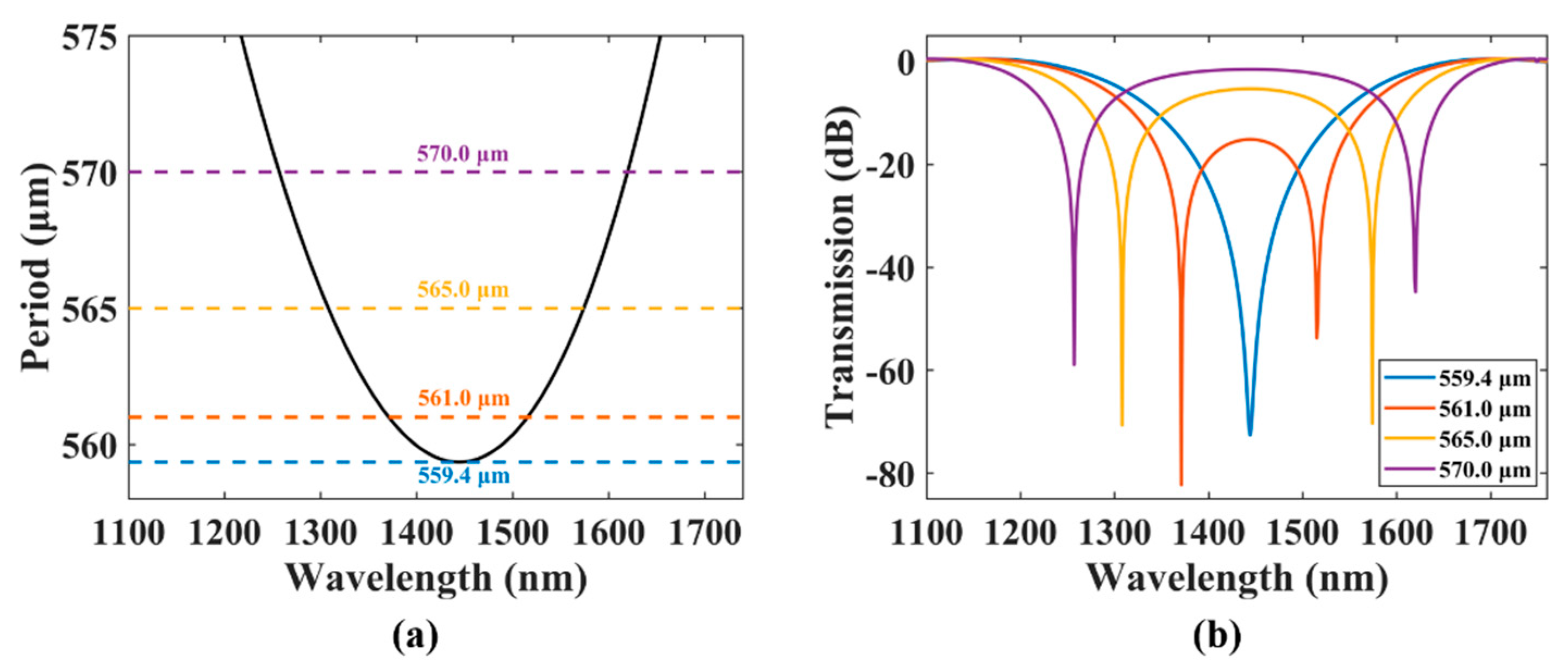
| 570.0 | 29.0 | 26.0 | 1243.0–1272.0 | 1606.0–1632.0 | 1257.0 | 1620.0 |
| 565.0 | 41.0 | 37.0 | 1289.0–1330.0 | 1554.0–1591.0 | 1308.0 | 1574.0 |
| 561.0 | 204.0 | 1340.0–1544.0 | 1371.0 | 1515.0 | ||
| 559.4 | 144.0 | 1371.0–1515.0 | 1444.0 | |||
| Author, Year | Methods | Bandwidth | Band/Central Wavelength | Bandwidth Adjustability | Working Band Adjustability |
|---|---|---|---|---|---|
| Zhao et al., 2016 | Tilted uniform LPFG [13] | 20 dB, 17.8 nm | 1507.0 nm | Yes | Yes |
| Rottwitt, 2016 | Chirped gratings [27] | 20 dB, 8.6 nm | 800.0 nm | Yes | No |
| Wang et al., 2017 | Length-apodized, long-period grating fabricated on a waveguide [32] | 20 dB, 150 nm | - | Yes | No |
| Guo et al., 2018 | Reduction in the number of grating periods [33] | 15 dB, 76.0 nm | 1567.2 nm | Yes | No |
| Zhao et al., 2019 | Cascading three linear length-apodized gratings [28] | 10 dB, 182.0 nm | C + L | Yes | Yes |
| Guo et al., 2019 | The double-resonance effect [29] | 15 dB, 118.2 nm | 1000.0 nm | Yes | No |
| Zhang et al., 2019 | Chiral LPFGs [34] | 10 dB, 25.0 nm | - | - | - |
| This work | BLPFG | 15 dB, 148.8 nm | 1303.4 nm | Yes | Yes |
| 15 dB, 168.5 nm | 1404.0 nm | ||||
| 15 dB, 180.0 nm; 20 dB, 130.2 nm | 1474.0 nm |
Publisher’s Note: MDPI stays neutral with regard to jurisdictional claims in published maps and institutional affiliations. |
© 2021 by the authors. Licensee MDPI, Basel, Switzerland. This article is an open access article distributed under the terms and conditions of the Creative Commons Attribution (CC BY) license (https://creativecommons.org/licenses/by/4.0/).
Share and Cite
Zheng, Y.; Guo, H.; Feng, M.; Wang, Z.; Liu, Y. Wavelength-Tunable, Ultra-Broadband, Biconical, Long-Period Fiber Grating Mode Converter Based on the Dual-Resonance Effect. Sensors 2021, 21, 5970. https://doi.org/10.3390/s21175970
Zheng Y, Guo H, Feng M, Wang Z, Liu Y. Wavelength-Tunable, Ultra-Broadband, Biconical, Long-Period Fiber Grating Mode Converter Based on the Dual-Resonance Effect. Sensors. 2021; 21(17):5970. https://doi.org/10.3390/s21175970
Chicago/Turabian StyleZheng, Yu, Huiyi Guo, Mao Feng, Zhi Wang, and Yange Liu. 2021. "Wavelength-Tunable, Ultra-Broadband, Biconical, Long-Period Fiber Grating Mode Converter Based on the Dual-Resonance Effect" Sensors 21, no. 17: 5970. https://doi.org/10.3390/s21175970