
Development of a Smart Leg Splint by Using New Sensor Technologies and New Therapy Possibilities

 , ,
, ,
Abstract
:1. Introduction
- Development of the protocol for scanning, meshing, designing and producing the splint.
- Development of mobile application for sensor monitoring.
- Implementation of an algorithm to detect inflammation through changes in pressure, temperature or colour of the affected area.
- Study on the measurement of humidity on the internal face of the splint, according to the discussion of convenience that will be done later in the article.
2. Materials and Methods
2.1. Sensing Technologies
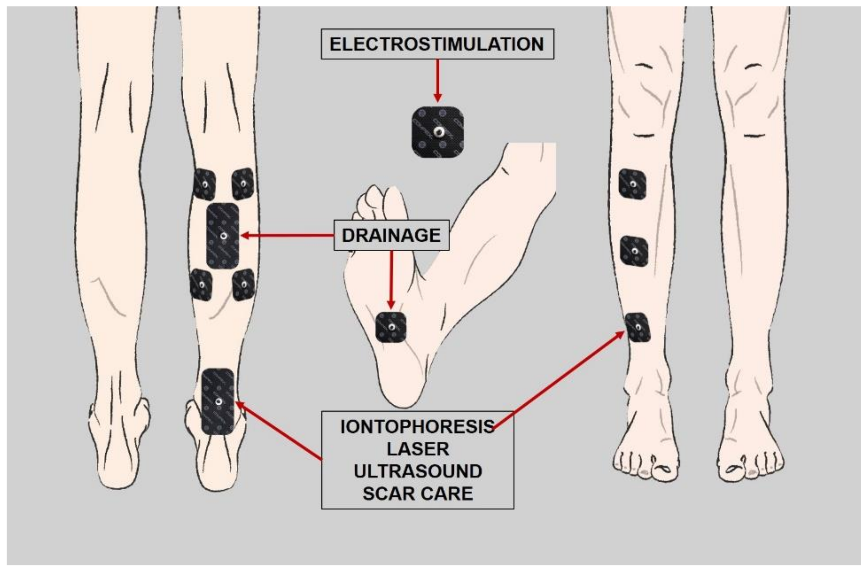
2.2. Considered Therapies during the Design Process
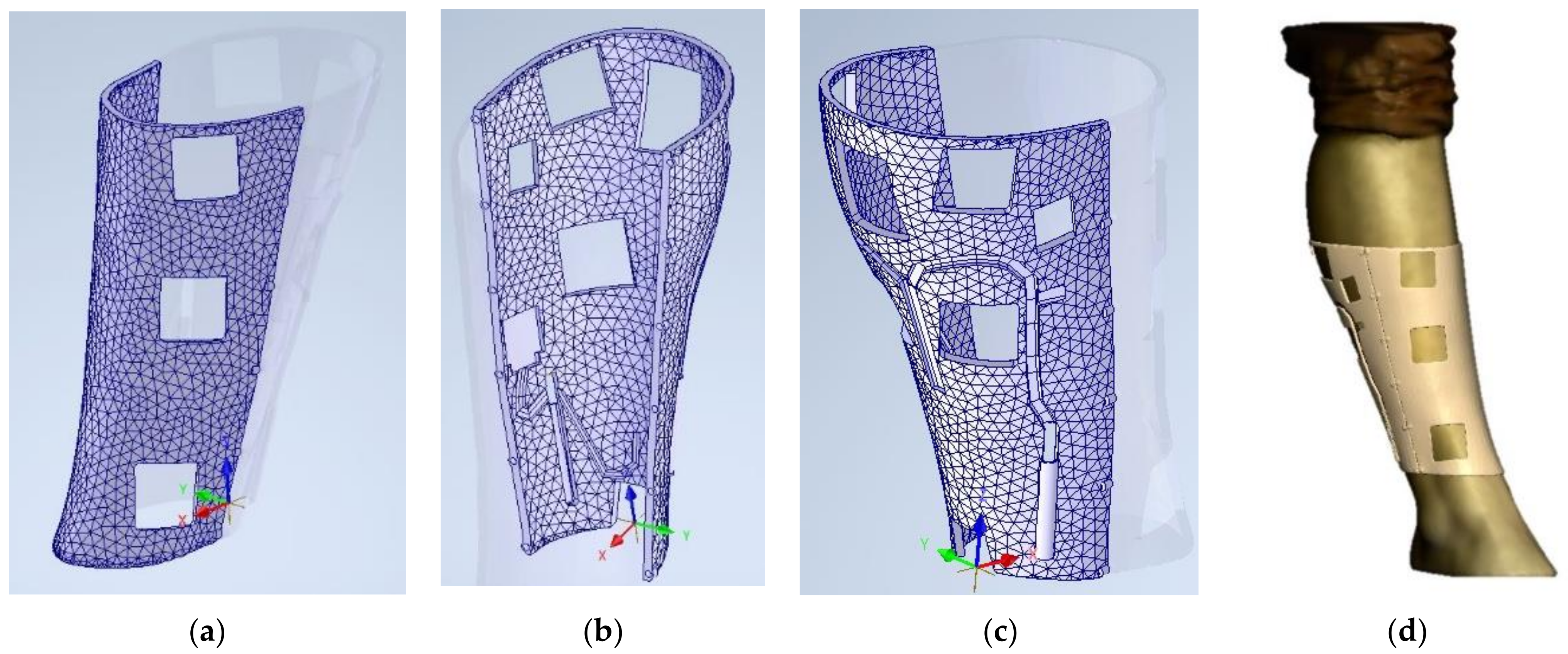
2.3. 3D Model and Design
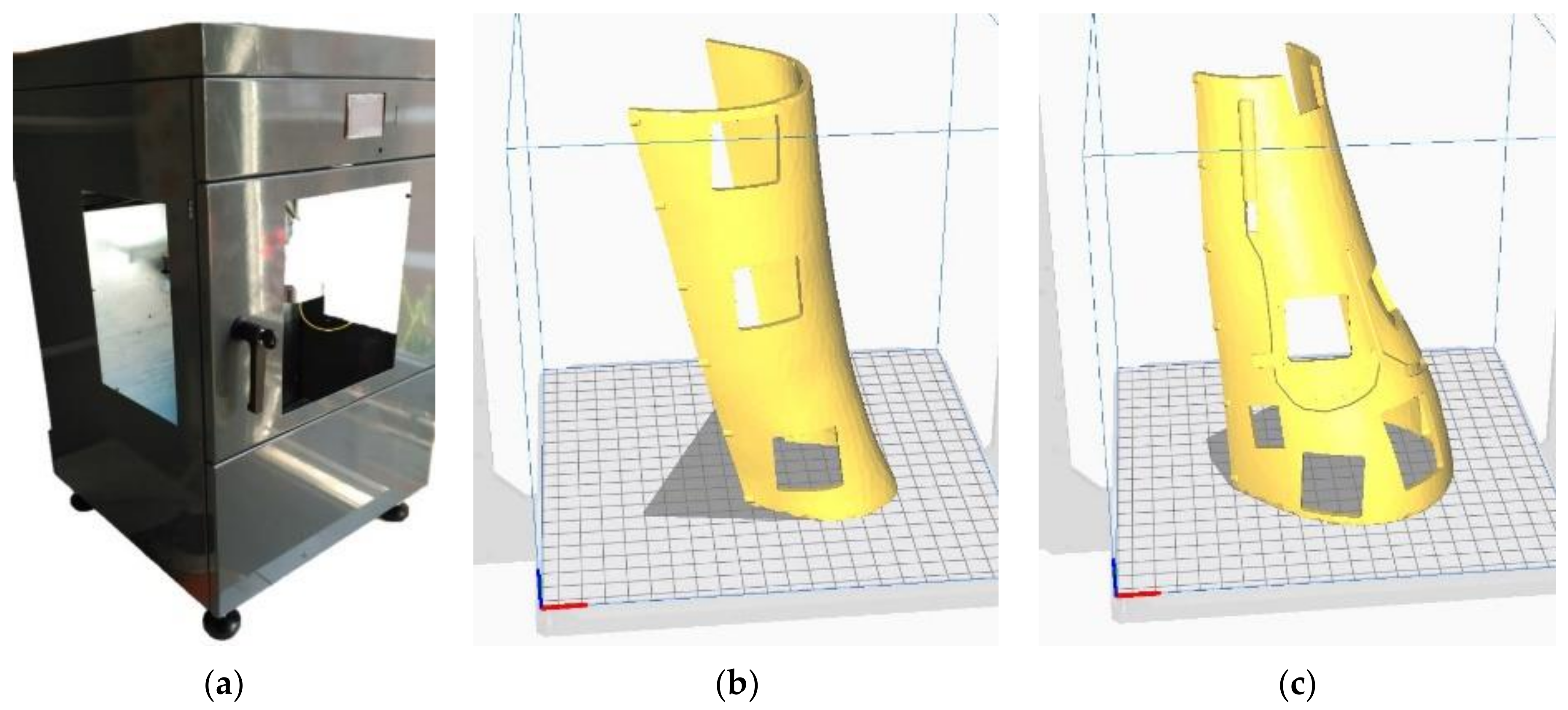
2.4. Additive Manufacturing
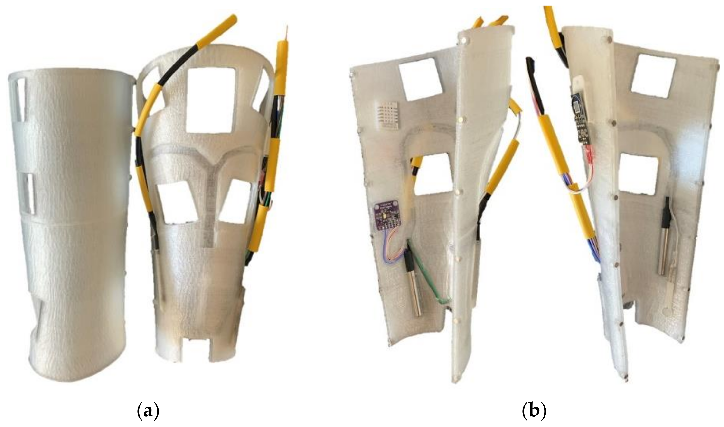
2.5. Sensing Technologies
3. Results
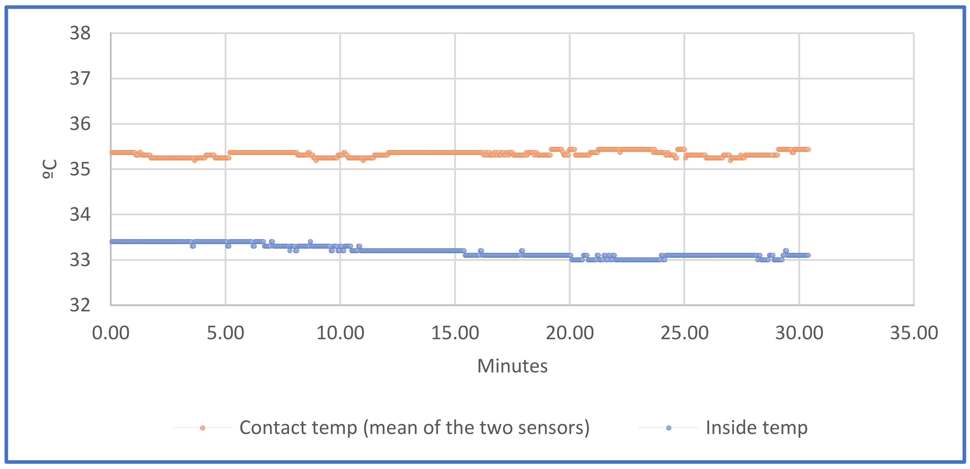
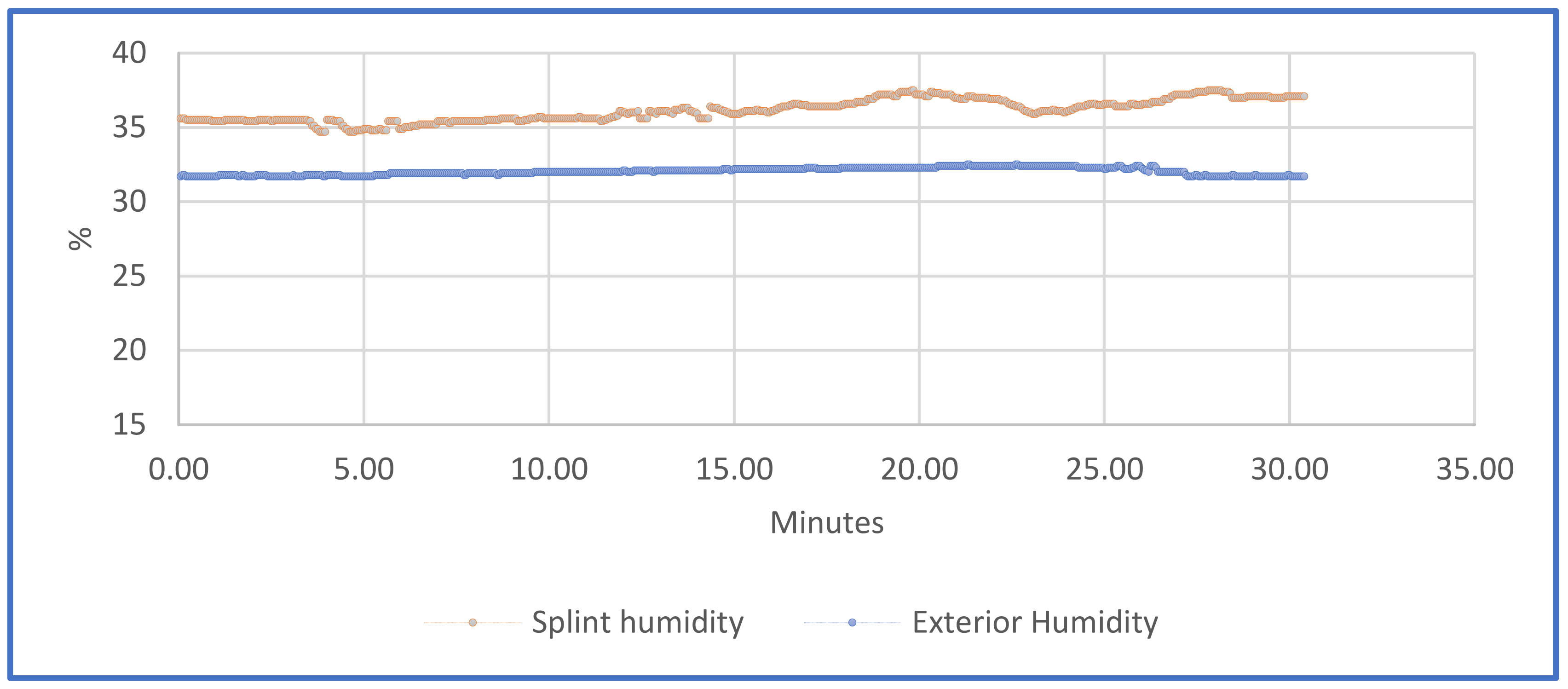
3.1. Temperatures and Humidity
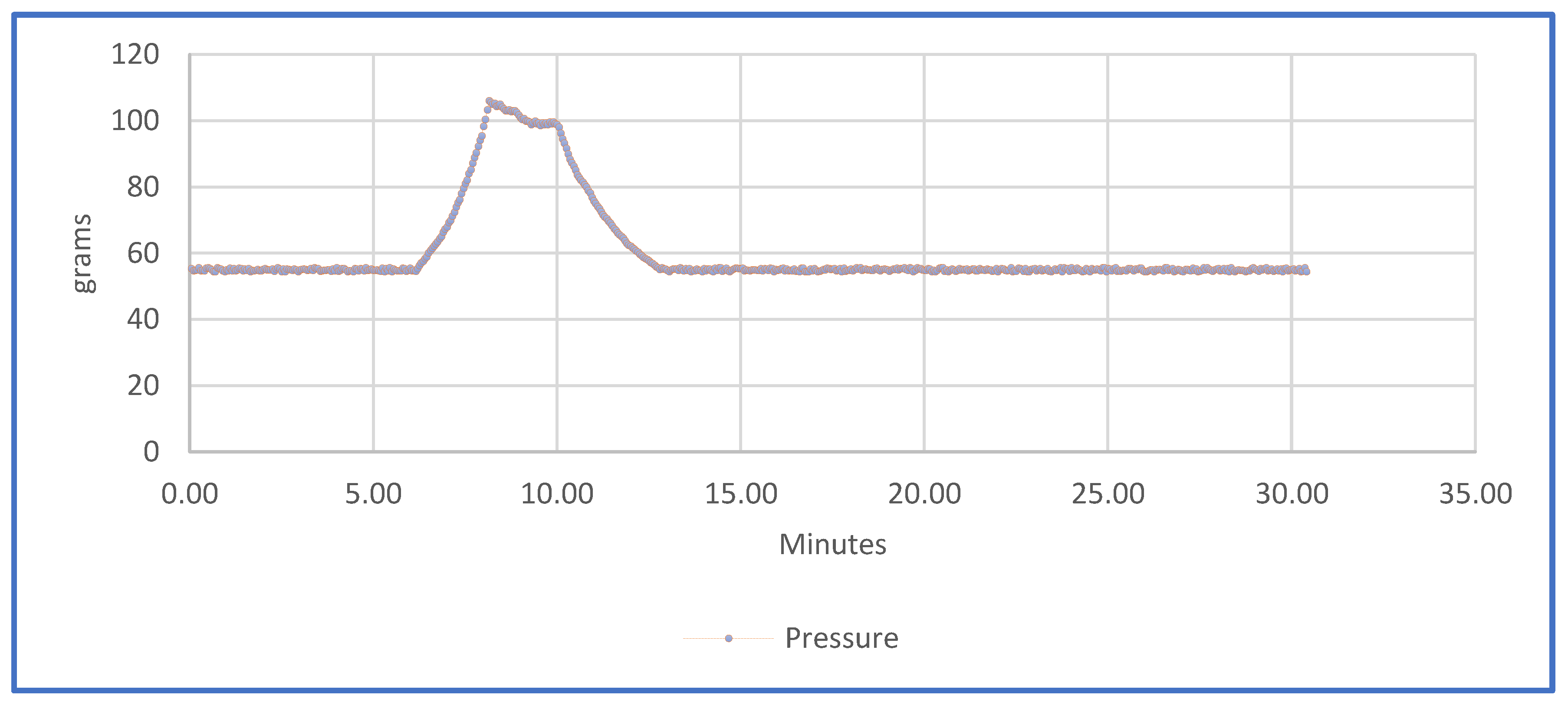
3.2. Pressure
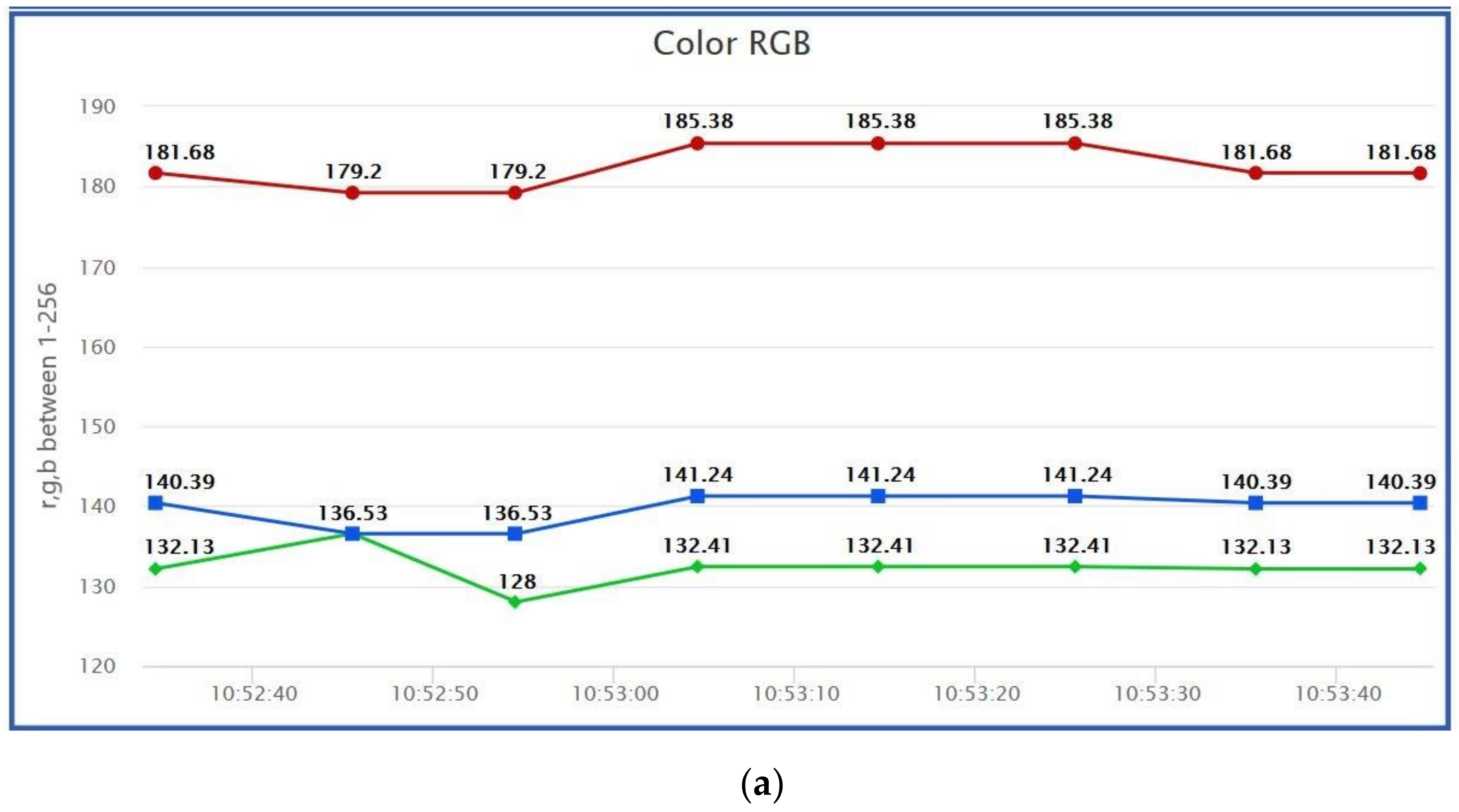
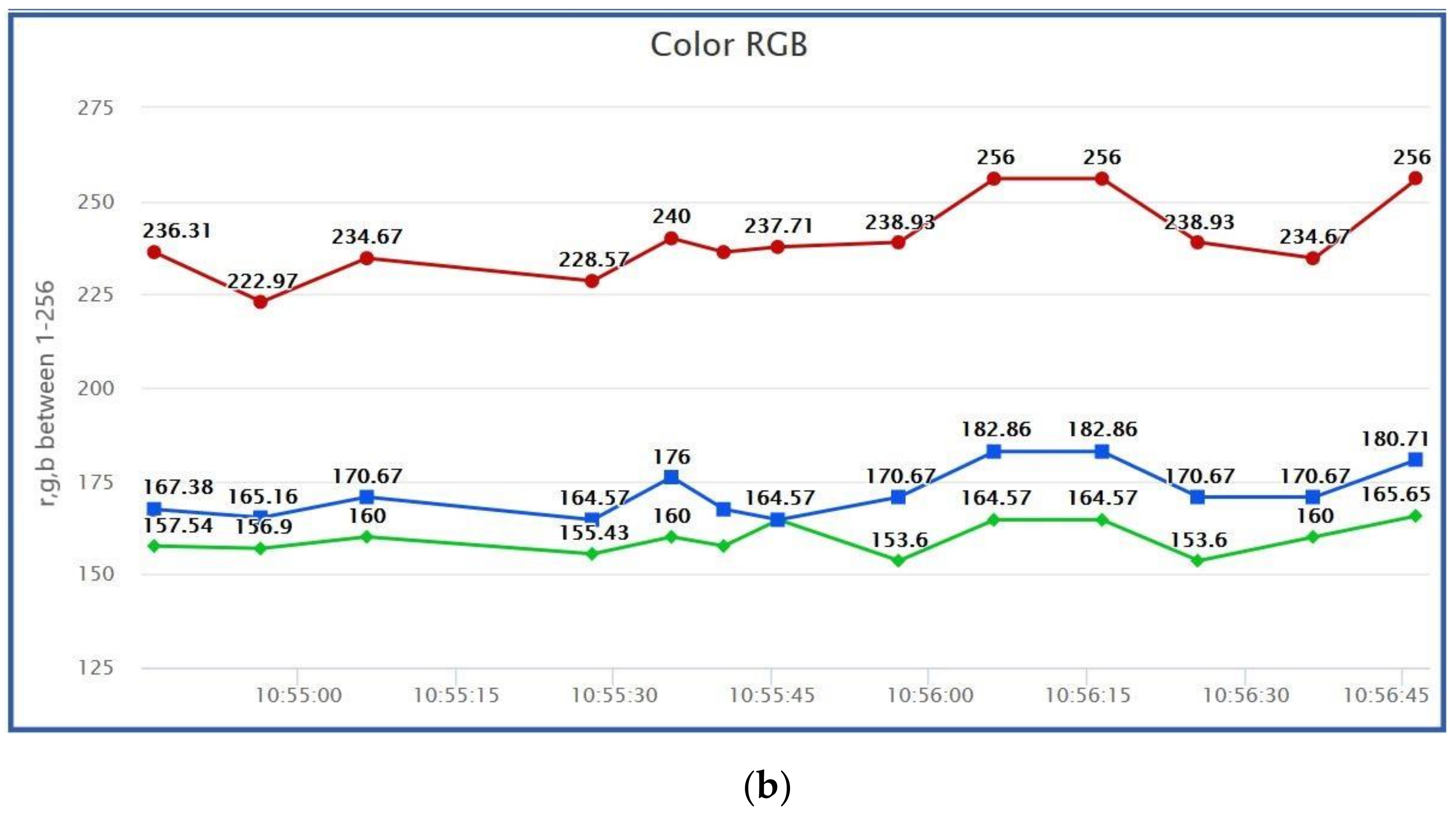
3.3. Colour
3.4. Diagnostic
4. Discussions
5. Conclusions
Author Contributions
Funding
Institutional Review Board Statement
Informed Consent Statement
Conflicts of Interest
References
- Miravete, A.L.C.-T. De Disseny, and Undefined 2002, “Materiales Compuestos,” Raco.Cat. Available online: https://www.raco.cat/index.php/Temes/article/view/29774 (accessed on 27 April 2020).
- Gebhardt, A.; Schmidt, F.-M.; Hötter, J.-S.; Sokalla, W.; Sokalla, P. Additive Manufacturing by selective laser melting the realizer desktop machine and its application for the dental industry. Phys. Procedia 2010, 5, 543–549. [Google Scholar] [CrossRef] [Green Version]
- Scholz, M.; Blanchfield, J.; Bloom, L.; Coburn, B.; Elkington, M.; Fuller, J.; Gilbert, M.; Muflahi, S.; Pernice, M.F.; Rae, S.; et al. The use of composite materials in modern orthopaedic medicine and prosthetic devices: A review. Compos. Sci. Technol. 2011, 71, 1791–1803. [Google Scholar] [CrossRef]
- Saringer, W.; Nöbauer-Huhmann, I.; Knosp, E. Cranioplasty with Individual Carbon Fibre Reinforced Polymere (CFRP) Medical Grade Implants Based on CAD/CAM Technique. Acta Neurochir. 2002, 144, 1193–1203. [Google Scholar] [CrossRef]
- Blaya, F.; Pedro, P.S.; Silva, J.L.; D’Amato, R.; Heras, E.S.; A Juanes, J. Design of an Orthopedic Product by Using Additive Manufacturing Technology: The Arm Splint. J. Med. Syst. 2018, 42, 54. [Google Scholar] [CrossRef] [PubMed]
- Melchels, F.; Domingos, M.; Klein, T.; Malda, J.; Bartolo, P.; Hutmacher, D.W. Additive manufacturing of tissues and organs. Prog. Polym. Sci. 2012, 37, 1079–1104. [Google Scholar] [CrossRef] [Green Version]
- Chia, H.N.; Wu, B.M. Recent advances in 3D printing of biomaterials. J. Biol. Eng. 2015, 9, 1–14. [Google Scholar] [CrossRef] [Green Version]
- Jose, R.R.; Rodriguez, M.J.; Dixon, T.A.; Omenetto, F.; Kaplan, D.L. Evolution of Bioinks and Additive Manufacturing Technologies for 3D Bioprinting. ACS Biomater. Sci. Eng. 2016, 2, 1662–1678. [Google Scholar] [CrossRef] [PubMed]
- Ambu, R.; Motta, A.; Calì, M. Design of a Customized Neck Orthosis for FDM Manufacturing with a New Sustainable Bio-composite. In Proceedings of the International Conference on Design, Simulation, Manufacturing: The Innovation Exchange, Modena, Italy, 9–10 September 2019; Springer: Berlin/Heidelberg, Germany, 2019; pp. 707–718. [Google Scholar]
- Blaya, F.; Pedro, P.S.; Pedro, A.B.S.; Lopez-Silva, J.; A Juanes, J.; D’Amato, R. Design of a Functional Splint for Rehabilitation of Achilles Tendon Injury Using Advanced Manufacturing (AM) Techniques. Implementation Study. J. Med. Syst. 2019, 43, 122. [Google Scholar] [CrossRef]
- McAuliffe, P.; Kim, J.H.; Diamond, D.; Lau, K.T.; O’Connell, B.C. A sleep bruxism detection system based on sensors in a splint—Pilot clinical data. J. Oral Rehabil. 2014, 42, 34–39. [Google Scholar] [CrossRef] [Green Version]
- Gao, J.; Liu, L.; Gao, P.; Zheng, Y.; Hou, W.; Wang, J. Intelligent Occlusion Stabilization Splint with Stress-Sensor System for Bruxism Diagnosis and Treatment. Sensors 2019, 20, 89. [Google Scholar] [CrossRef] [Green Version]
- Yin, Y.; Zeng, Y.; Chen, X.; Fan, Y. The internet of things in healthcare: An overview. J. Ind. Inf. Integr. 2016, 1, 3–13. [Google Scholar] [CrossRef]
- Dimitrov, D.V. Medical Internet of Things and Big Data in Healthcare. Healthc. Inform. Res. 2016, 22, 156–163. [Google Scholar] [CrossRef]
- Fan, Y.J.; Yin, Y.H.; Da Xu, L.; Zeng, Y.; Wu, F. IoT-Based Smart Rehabilitation System. IEEE Trans. Ind. Inform. 2014, 10, 1568–1577. [Google Scholar] [CrossRef]
- De Agustín Del Burgo, J.M.; Blaya Haro, F.; D’Amato, R.; Juanes Méndez, J.A. Development of a Smart Splint to Monitor Different Parameters during the Treatment Process. Sensors 2020, 20, 4207. [Google Scholar] [CrossRef]
- Ju, X.; Nebel, J.-C.; Siebert, J.P. 3D thermography imaging standardization technique for inflammation diagnosis. In Infrared Components and Their Applications; SPIE: Washington, DC, USA, 2005; Volume 5640, pp. 266–273. [Google Scholar]
- Schlereth, T.; Drummond, P.D.; Birklein, F. Inflammation in CRPS: Role of the sympathetic supply. Auton. Neurosci. 2014, 182, 102–107. [Google Scholar] [CrossRef] [PubMed] [Green Version]
- International Society of Lymphology. The diagnosis and treatment of peripheral lymphedema: 2016 consensus document of the International Society of Lymphology. Lymphology 2016, 49, 170–184. [Google Scholar]
- Chikly, B.; Quaghebeur, J.; Wytryol, W. A Controlled Comparison between Manual Lymphatic Mapping (MLM) of Plantar Lymph Flow and Standard Physiologic Maps Using Lymph Drainage Therapy (LDT)/Osteopathic Lymphatic Technique (OLT). Qual. Prim. Care 2015, 23, 46–50. [Google Scholar] [CrossRef]
- Wei, Y.; Yang, K.; Browne, M.; Bostan, L.; Worsley, P. Wearable Electrical Stimulation to Improve Lymphatic Function. IEEE Sens. Lett. 2019, 3, 1–4. [Google Scholar] [CrossRef]
- Hamann, H.; Hodges, M.; Evans, B. Effectiveness of iontophoresis of anti-inflammatory medications in the treatment of common musculoskeletal inflammatory conditions: A systematic review. Phys. Ther. Rev. 2006, 11, 190–194. [Google Scholar] [CrossRef]
- Costello, C.T.; Jeske, A.H. Iontophoresis: Applications in Transdermal Medication Delivery. Phys. Ther. 1995, 75, 554–563. [Google Scholar] [CrossRef] [PubMed]
- Rigby, J.H.; Mortensen, B.B.; Draper, D.O. Wireless Versus Wired Iontophoresis for Treating Patellar Tendinopathy: A Randomized Clinical Trial. J. Athl. Train. 2015, 50, 1165–1173. [Google Scholar] [CrossRef] [Green Version]
- Hao, J. Topical iontophoresis for local therapeutic effects. J. Drug Deliv. Sci. Technol. 2014, 24, 255–258. [Google Scholar] [CrossRef]
- Taskaynatan, M.A.; Özgül, A.; Ozdemir, A.; Tan, A.K.; Kalyon, T.A. Effects of Steroid Iontophoresis and Electrotherapy on Bicipital Tendonitis. J. Musculoskelet. Pain 2007, 15, 47–54. [Google Scholar] [CrossRef]
- Neeter, C.; Thomee, R.; Silbernagel, K.G.; Thomee, P.; Karlsson, J. Iontophoresis with or without dexamethazone in the treatment of acute Achilles tendon pain. Scand. J. Med. Sci. Sports 2003, 13, 376–382. [Google Scholar] [CrossRef] [PubMed] [Green Version]
- Baker, K.G.; Robertson, V.J.; Duck, F.A. A Review of Therapeutic Ultrasound: Biophysical Effects. Phys. Ther. 2001, 81, 1351–1358. [Google Scholar] [CrossRef] [PubMed] [Green Version]
- Robertson, V.J.; Baker, K.G. A Review of Therapeutic Ultrasound: Effectiveness Studies. Phys. Ther. 2001, 81, 1339–1350. [Google Scholar] [CrossRef] [PubMed] [Green Version]
- Bjordal, J.M.; Iversen, V.; Lopes-Martins, R.A.B. Low level laser therapy reduces inflammation in activated Achilles tendinitis. In Mechanisms for Low-Light Therapy; SPIE: Washington, DC, USA, 2006; Volume 6140. [Google Scholar]
- Ebenbichler, G.R.; Erdogmus, C.B.; Resch, K.L.; Funovics, M.A.; Kainberger, F.; Barisani, G.; Aringer, M.; Nicolakis, P.; Wiesinger, G.F.; Baghestanian, M.; et al. Ultrasound Therapy for Calcific Tendinitis of the Shoulder. N. Engl. J. Med. 1999, 340, 1533–1538. [Google Scholar] [CrossRef]
- Rigby, J.H.; Taggart, R.M.; Stratton, K.L.; Lewis, G.K.; Draper, D.O. Intramuscular Heating Characteristics of Multihour Low-Intensity Therapeutic Ultrasound. J. Athl. Train. 2015, 50, 1158–1164. [Google Scholar] [CrossRef] [Green Version]
- Mitragotri, S. Healing sound: The use of ultrasound in drug delivery and other therapeutic applications. Nat. Rev. Drug Discov. 2005, 4, 255–260. [Google Scholar] [CrossRef]
- Kneebone, W. The Treatment of Achilles Tendonitis Using Therapeutic Laser. 2010. Available online: http://orthopedics.about.com/cs/ankleproblems/a/ (accessed on 27 April 2020).
- Tumilty, S.; Munn, J.; McDonough, S.; Hurley, D.A.; Basford, J.R.; Baxter, G.D. Low Level Laser Treatment of Tendinopathy: A Systematic Review with Meta-Analysis. Photomed. Laser Surg. 2010, 28, 3–16. [Google Scholar] [CrossRef]
- Bjordal, J.M.; Lopes-Martins, R.; Álvaro, B.; Joensen, J.; Iversen, V.V. The anti-inflammatory mechanism of low level laser therapy and its relevance for clinical use in physiotherapy. Phys. Ther. Rev. 2010, 15, 286–293. [Google Scholar] [CrossRef]
- Karu, T.I. Mitochondrial Signaling in Mammalian Cells Activated by Red and Near-IR Radiation. Photochem. Photobiol. 2008, 84, 1091–1099. [Google Scholar] [CrossRef]
- Moriyama, Y.; Nguyen, J.; Akens, M.; Moriyama, E.H.; Lilge, L. In vivo effects of low level laser therapy on inducible nitric oxide synthase. Lasers Surg. Med. 2009, 41, 227–231. [Google Scholar] [CrossRef]
- Gao, X.; Xing, D. Molecular mechanisms of cell proliferation induced by low power laser irradiation. J. Biomed. Sci. 2009, 16, 4. [Google Scholar] [CrossRef] [PubMed] [Green Version]
- Reddy, G.K.; Stehno-Bittel, L.; Enwemeka, C.S. Laser photostimulation of collagen production in healing rabbit achilles tendons. Lasers Surg. Med. 1998, 22, 281–287. [Google Scholar] [CrossRef]
- Ng, G.Y.; Fung, D.T. The Combined Treatment Effects of Therapeutic Laser and Exercise on Tendon Repair. Photomed. Laser Surg. 2008, 26, 137–141. [Google Scholar] [CrossRef] [PubMed]
- Msc, L.I.F.; Mauriz, J.L.; Vedovelli, K.; Msc, A.J.M.; Zettler, C.G.; Lech, O.; Marroni, N.P.; González-Gallego, J. Low-level laser therapy (LLLT) prevents oxidative stress and reduces fibrosis in rat traumatized Achilles tendon. Lasers Surg. Med. 2005, 37, 293–300. [Google Scholar] [CrossRef]
- Aimbire, F.; Albertini, R.; Pacheco, M.T.T.; Castro-Faria-Neto, H.; Leonardo, P.; Iversen, V.; Lopes-Martins, R.; Bjordal, J. Low-Level Laser Therapy Induces Dose-Dependent Reduction of TNFα Levels in Acute Inflammation. Photomed. Laser Surg. 2006, 24, 33–37. [Google Scholar] [CrossRef] [PubMed]
- Joensen, J.; Gjerdet, N.R.; Hummelsund, S.; Iversen, V.; Lopes-Martins, R.A.; Bjordal, J.M. An experimental study of low-level laser therapy in rat Achilles tendon injury. Lasers Med. Sci. 2012, 27, 103–111. [Google Scholar] [CrossRef] [Green Version]
- Heidland, A.; Fazeli, G.; Klassen, A.; Sebekova, K.; Hennemann, H.; Bahner, U.; Di Iorio, B. Neuromuscular electrostimulation techniques: Historical aspects and current possibilities in treatment of pain and muscle waisting. Clin. Nephrol. 2012, 79. [Google Scholar] [CrossRef]
- Rosemffet, M.G.; Schneeberger, E.E.; Citera, G.; Sgobba, M.E.; Laiz, C.; Schmulevich, H.; Artçanuturry, P.; Gagliardi, S.; Cocco, J.A.M. Effects of Functional Electrostimulation on Pain, Muscular Strength, and Functional Capacity in Patients with Osteoarthritis of the Knee. JCR J. Clin. Rheumatol. 2004, 10, 246–249. [Google Scholar] [CrossRef]
- Johansson, K.; Albertsson, M.; Ingvar, C.; Ekdahl, C. Effects of compression bandaging with or without manual lymph drainage treatment in patients with postoperative arm lymphedema. Lymphology 1999, 32, 103–110. [Google Scholar]
- Aiyejusunle, C.B.; Kola-Korolo, T.A.; Ajiboye, O.A. Comparison of the effects of tens and sodium salicylate iontophoresis in the management of osteoarthritits of the knee. Niger. Q. J. Hosp. Med. 2007, 17, 30–34. [Google Scholar] [CrossRef] [PubMed]
- Stasinopoulos, D.I.; Johnson, M.I. Effectiveness of Low-Level Laser Therapy for Lateral Elbow Tendinopathy. Photomed. Laser Surg. 2005, 23, 425–430. [Google Scholar] [CrossRef] [Green Version]
- Kaplan, K.; Olivencia, O.; Dreger, M.; Hanney, W.J.; Kolber, M.J. Achilles Tendinopathy: An Evidence-Based Overview for the Sports Medicine Professional. Strength Cond. J. 2019, 41, 24–40. [Google Scholar] [CrossRef]
- Moein, H.; Jhalli, R.; Blaber, A.P.; Claydon, V.E.; Menon, C. Evaluating the efficacy of an active compression brace on orthostatic cardiovascular responses. PLoS ONE 2017, 12, e0187885. [Google Scholar] [CrossRef] [Green Version]
- Dallas Semiconductor. Programmable Resolution 1-Wire® Digital Thermometer with 4-Bit ID. 2002. Available online: http://ee-classes.usc.edu/ee459/library/datasheets/DS18B20.pdf (accessed on 19 March 2021).
- Aosong Electronics Co., Ltd. Digital-Output Relative Humidity & Temperature Sensor/Module DHT22 (DHT22 Also Named as AM2302). 2015. Available online: https://www.sparkfun.com/datasheets/Sensors/Temperature/DHT22.pdf (accessed on 6 June 2021).
- Film Pressure Sensor DF9-40@10 kg V2.0. Available online: https://www.winsen-sensor.com/d/files/df9-40%4010kg.pdf (accessed on 6 June 2021).
- TCS3472 Color Light-to-Digital Converter with IR Filter. Available online: https://cdn-shop.adafruit.com/datasheets/TCS34725.pdf (accessed on 30 April 2020).
- Bruise Colors: Causes, Timescale, and When to See a Doctor. Available online: https://www.medicalnewstoday.com/articles/322742#bruise-colors-over-time-and-their-causes (accessed on 13 July 2021).
- Tell-Tale Color Changes: Camera Can Find Age of a Bruise|Features|Oct 2012|BioPhotonics. Available online: https://www.photonics.com/Articles/TellTale_Color_Changes_Camera_Can_Find_Age_of_a/a52130 (accessed on 13 July 2021).
- Patašius, M.; Marozas, V.; Jegelevičius, D.; Lukoševičius, A.; Data Exploration for Hematoma Image Analysis. February 2016. Available online: http://biomed.ktu.lt/index.php/BME/article/view/2481 (accessed on 13 May 2021).
- Al Ghozali, H.K.; Setiawardhana; Sigit, R. Vein detection system using infrared camera. In Proceedings of the 2016 International Electronics Symposium (IES), Denpasar, Indonesia, 29–30 September 2016; pp. 122–127. [Google Scholar] [CrossRef]
- Automatización de la Datación de Equimosis en el Peritaje Médico Legal Peruano Mediante Redes Neuronales Artificiales y Procesamiento de Imágenes. Available online: http://cybertesis.unmsm.edu.pe/handle/20.500.12672/1071 (accessed on 26 May 2021).
- Pourlak, T.; Ghavimi, M.A.; Nezafati, S.; Yazdani, J.; Amini, M.; Pourlak, T.; Ghoreishizadeh, A.; Negahdari, R. Comparison of edema and ecchymosis in rhinoplasty candidates after lateral nasal osteotomy using piezosurgery and external osteotomy. J. Adv. Pharm. Technol. Res. 2018, 9, 73–79. [Google Scholar] [CrossRef]
- Gurlek, A.; Fariz, A.; Aydogan, H.; Ersoz-Ozturk, A.; Eren, A.T. Effects of Different Corticosteroids on Edema and Ecchymosis in Open Rhinoplasty. Aesthet. Plast. Surg. 2006, 30, 150–154. [Google Scholar] [CrossRef] [PubMed]
- Nurunnabi, A.; West, G.; Belton, D. Outlier detection and robust normal-curvature estimation in mobile laser scanning 3D point cloud data. Pattern Recognit. 2015, 48, 1404–1419. [Google Scholar] [CrossRef] [Green Version]
- Rakotosaona, M.; La Barbera, V.; Guerrero, P.; Mitra, N.J.; Ovsjanikov, M. PointCleanNet: Learning to Denoise and Remove Outliers from Dense Point Clouds. Comput. Graph. Forum 2020, 39, 185–203. [Google Scholar] [CrossRef] [Green Version]
- Farah, S.; Anderson, D.G.; Langer, R. Physical and mechanical properties of PLA, and their functions in widespread applications—A comprehensive review. Adv. Drug Deliv. Rev. 2016, 107, 367–392. [Google Scholar] [CrossRef] [Green Version]
- Heras, E.S.; Haro, F.B.; De Agustin del Burgo, J.M.; Marcos, M.I.; D’Amato, R. Filament Advance Detection Sensor for Fused Deposition Modelling 3D Printers. Sensors 2018, 18, 1495. [Google Scholar] [CrossRef] [PubMed] [Green Version]
- Haro, F.B.; De Agustin del Burgo, J.M.; D’Amato, R.; Islán, M.; Heras, E.S.; Alonso, J.M.G.; Mendez, J.A.J. Monitoring an Analysis of Perturbations in Fusion Deposition Modelling (FDM) Processes for the Use of Biomaterials. J. Med. Syst. 2019, 43, 109. [Google Scholar] [CrossRef] [PubMed]
- Haro, F.B.; De Agustin del Burgo, J.M.; D’Amato, R.; Marcos, M.I.; Heras, E.S.; Alonso, J.M.G. Monitoring of the additive manufacturing process for the use of biomaterials in medical field. In Proceedings of the Sixth International Conference on Technological Ecosystems for Enhancing Multiculturality, Salamanca, Spain, 24–26 October 2018; Association for Computing Machinery (ACM): New York, NY, USA, 2018; pp. 428–432. [Google Scholar]
- De Agustin del Burgo, J.M.; D’Amato, R.; Méndez, J.A.J.; Ramírez, A.S.; Haro, F.B.; Heras, E.S. Real time analysis of the filament for FDM 3D printers. In Proceedings of the Seventh International Conference on Technological Ecosystems for Enhancing Multiculturality, León, Spain, 16–18 October 2019; pp. 354–360. [Google Scholar]
- Vladescu, A.; Braic, M.; Azem, F.A.; Titorencu, I.; Braic, V.; Pruna, V.; Kiss, A.; Parau, A.C.; Birlik, I. Effect of the deposition temperature on corrosion resistance and biocompatibility of the hydroxyapatite coatings. Appl. Surf. Sci. 2015, 354, 373–379. [Google Scholar] [CrossRef]
- Salentijn, G.; Oomen, P.E.; Grajewski, M.; Verpoorte, E. Fused Deposition Modeling 3D Printing for (Bio)analytical Device Fabrication: Procedures, Materials, and Applications. Anal. Chem. 2017, 89, 7053–7061. [Google Scholar] [CrossRef] [Green Version]
- ESP32 Series Datasheet Including. 2020. Available online: https://www.espressif.com/en/support/download/documents (accessed on 28 April 2020).
- Birklein, F.; Künzel, W.; Sieweke, N. Despite clinical similarities there are significant differences between acute limb trauma and complex regional pain syndrome I (CRPS I). Pain 2001, 93, 165–171. [Google Scholar] [CrossRef]
- Jänig, W. Functions of the Sympathetic Innervation of the Skin; Loewy, A.D., Spyer, K.M., Eds.; Central Regulation of Autonomic Functions, Oxford University Press: New York, NY, USA, 1990; pp. 334–348. [Google Scholar]
- Lowe, D.T. Cupping therapy: An analysis of the effects of suction on skin and the possible influence on human health. Complement. Ther. Clin. Pract. 2017, 29, 162–168. [Google Scholar] [CrossRef]
- Kim, Y.; Son, S.; Chun, C.; Kim, J.-T.; Lee, D.Y.; Choi, H.J.; Kim, T.-H.; Cha, E.-J. Effect of PEG addition on pore morphology and biocompatibility of PLLA scaffolds prepared by freeze drying. Biomed. Eng. Lett. 2016, 6, 287–295. [Google Scholar] [CrossRef]
- Hernández, J.A.J.; Vicente, E.J.G.; Sánchez, F.R.; Sánchez, F.M.; Rodríguez, M.P.C.; Morote, J.P. Prevención de úlceras iatrogénicas por inmovilización terapéutica en niños con férula. Ensayo clínico. Enferm. Glob. 2020, 19, 135–154. [Google Scholar] [CrossRef]


| Sensor Serial Number | DS18B20 | DHT22 | DF9-40 | TCS34725 |
|---|---|---|---|---|
| Dimensions (mm) | 6 × 6 × 50 | 15 × 7.7 × 20 | 40 × 20 × 0.25 | 25 × 20 × 1.5 |
| Power voltage (V) | 3.0–5.5 | 3.3–6 | 5 | 5 |
| Working range | −55 °C to 125 °C | −40 °C to 80 °C 0 to 100% RH | 0–500 g | - |
| Resolution | ±0.0625 °C | 0.1 °C, 0.1% RH | 14.5 g | - |
| Maximum Scan Volume | 2 × 2 × 2 [m] |
| Minimum Scan Volume | 0.2 × 0.2 × 0.2 [m] |
| Working Distance | 0.2–1.6 [m] |
| Number of Cameras n | 2 |
| Class Certified Laser Product | 1 |
| Resolution at 0.5 m | 1 [mm] |
| Properties | Units | PLA |
|---|---|---|
| ρ (Polymer density) | g/cm3 | 1.21–1.25 |
| σ (tensile strength) | MPa | 21.0–60.0 |
| E (tensile modulus) | GPa | 0.35–3.50 |
| ɛ (ultimate strain) | % | 2.50–6.00 |
| σs (specific tensile strength) | Nm/g | 16.8–48.0 |
| Es (specific tensile modulus) | kNm/g | 0.28–2.80 |
| Tg (glass transition temperature) | °C | 45–60 |
| Tm (melting temperature) | °C | 150–162 |
| Layer height [mm] | 0.2 |
| Extruder [mm] | 0.4 |
| Density [%] | 40 |
| Thickness perimeter each layer [mm] | 1 |
| Print speed [mm/s] | 60 |
| Temperature [°C] | 220 |
| Temperature increment | 1.5 °C |
| Pressure increment | 60 gf/cm2 |
| Time during temperature increment | 60 m |
| Time during pressure increment | 60 m |
Publisher’s Note: MDPI stays neutral with regard to jurisdictional claims in published maps and institutional affiliations. |
© 2021 by the authors. Licensee MDPI, Basel, Switzerland. This article is an open access article distributed under the terms and conditions of the Creative Commons Attribution (CC BY) license (https://creativecommons.org/licenses/by/4.0/).
Share and Cite
De Agustín Del Burgo, J.M.; Blaya Haro, F.; D’Amato, R.; Blaya, A.; Juanes Méndez, J.A. Development of a Smart Leg Splint by Using New Sensor Technologies and New Therapy Possibilities. Sensors 2021, 21, 5252. https://doi.org/10.3390/s21155252
De Agustín Del Burgo JM, Blaya Haro F, D’Amato R, Blaya A, Juanes Méndez JA. Development of a Smart Leg Splint by Using New Sensor Technologies and New Therapy Possibilities. Sensors. 2021; 21(15):5252. https://doi.org/10.3390/s21155252
Chicago/Turabian StyleDe Agustín Del Burgo, José María, Fernando Blaya Haro, Roberto D’Amato, Alonso Blaya, and Juan Antonio Juanes Méndez. 2021. "Development of a Smart Leg Splint by Using New Sensor Technologies and New Therapy Possibilities" Sensors 21, no. 15: 5252. https://doi.org/10.3390/s21155252