Design of Carryable Intravenous Drip Frame with Automatic Balancing

 and
and
Abstract
:1. Introduction
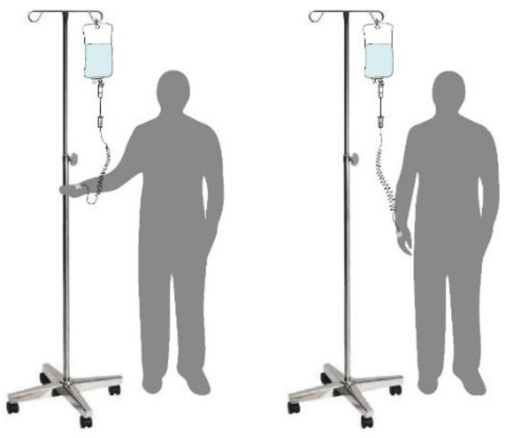
- The device can be moved with the human body
- The system can cooperate with shoulder activities and neck activities
- The control mechanism can correct the tilting angle of the body forward and automatically restore the angle
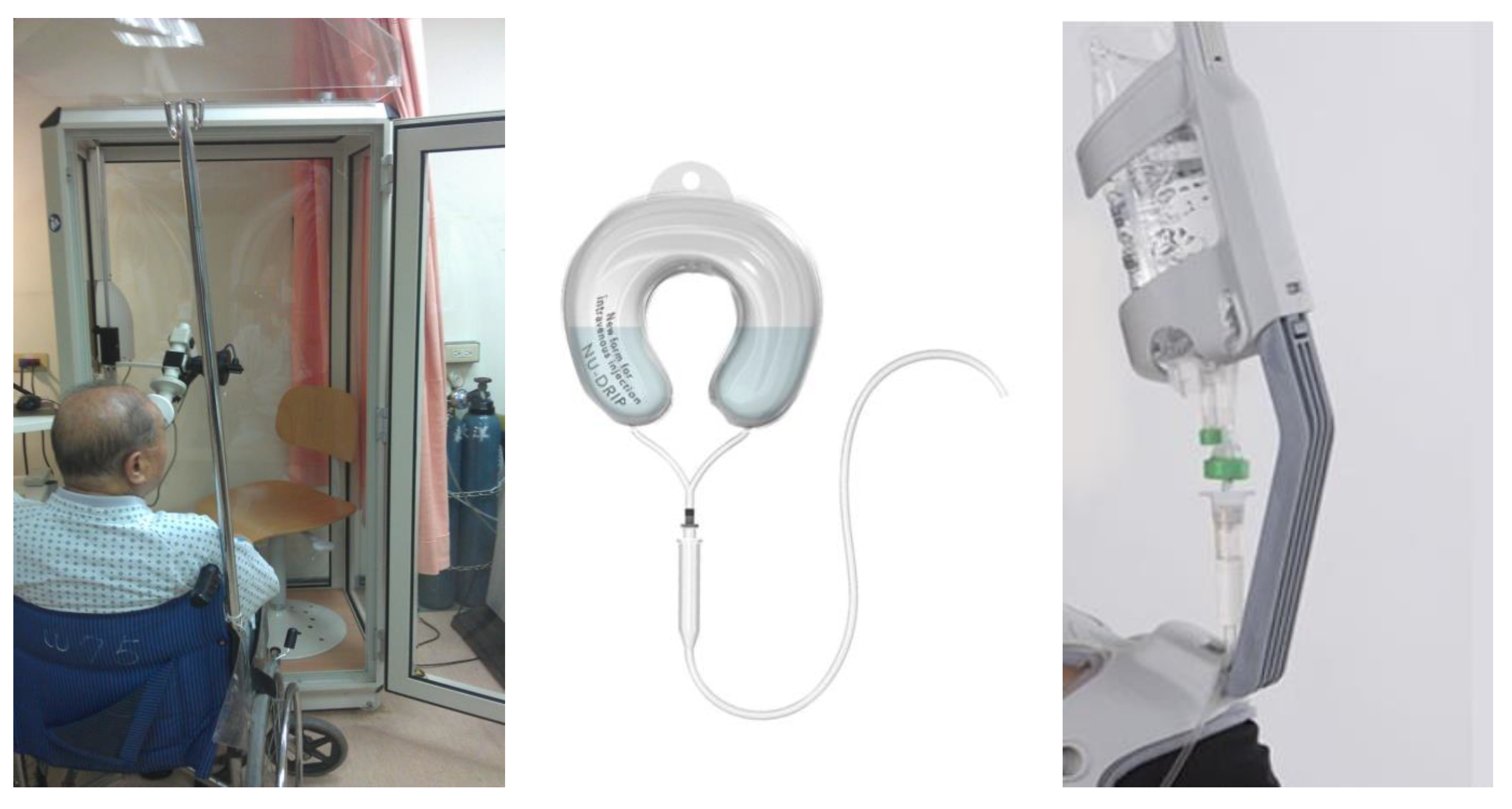
2. Related Works
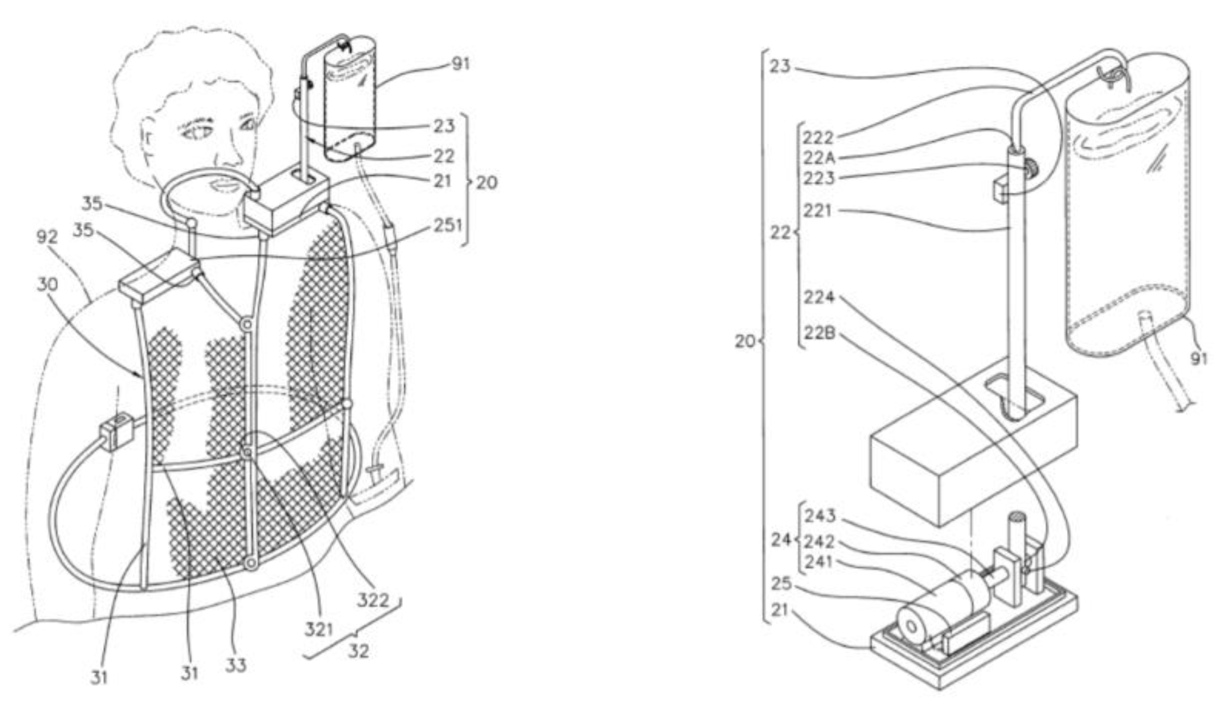
3. System Description
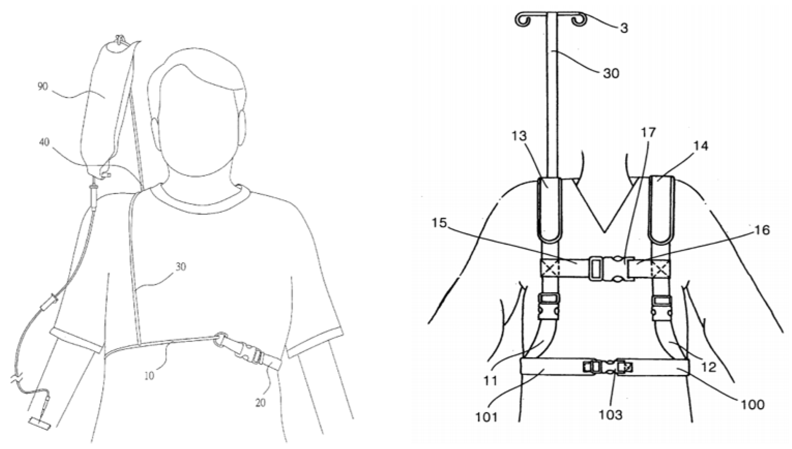
3.1. Drip Frame
3.2. Angle Calculation
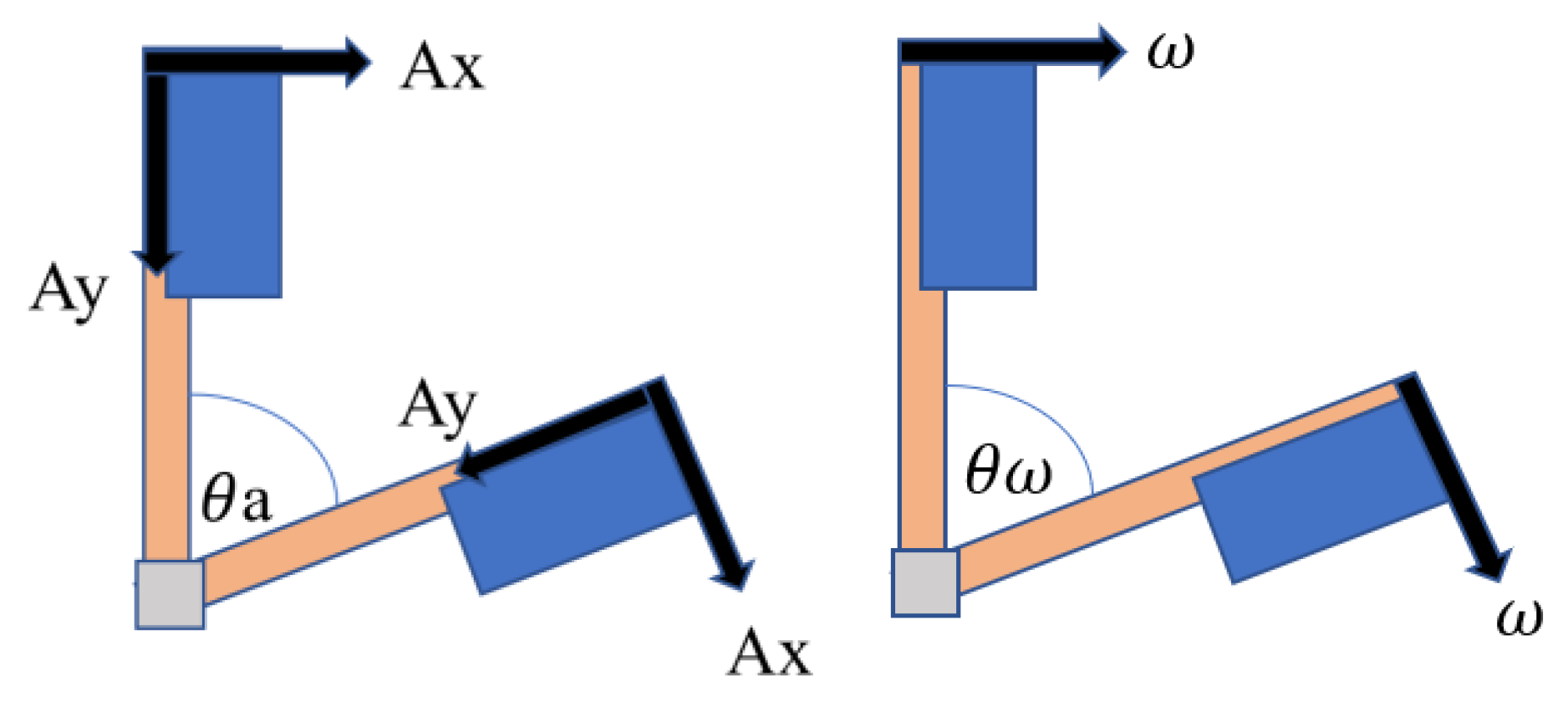
3.2.1. Acceleration
3.2.2. Angular Velocity
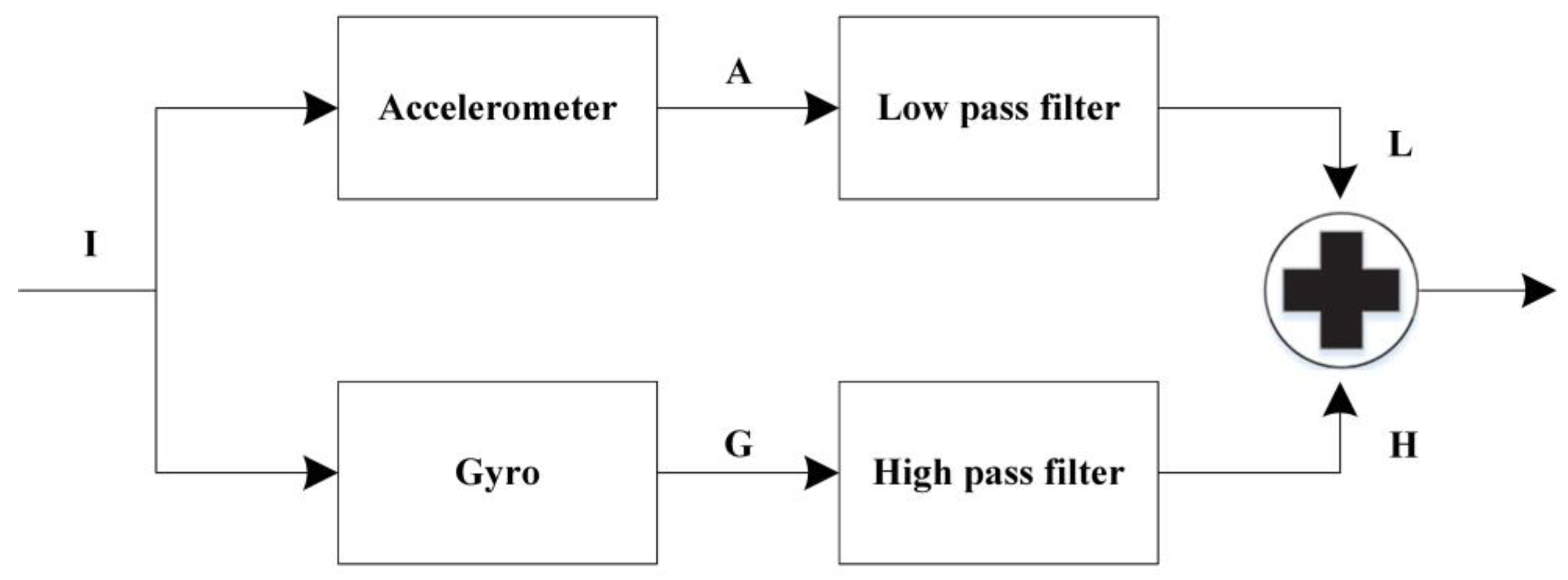
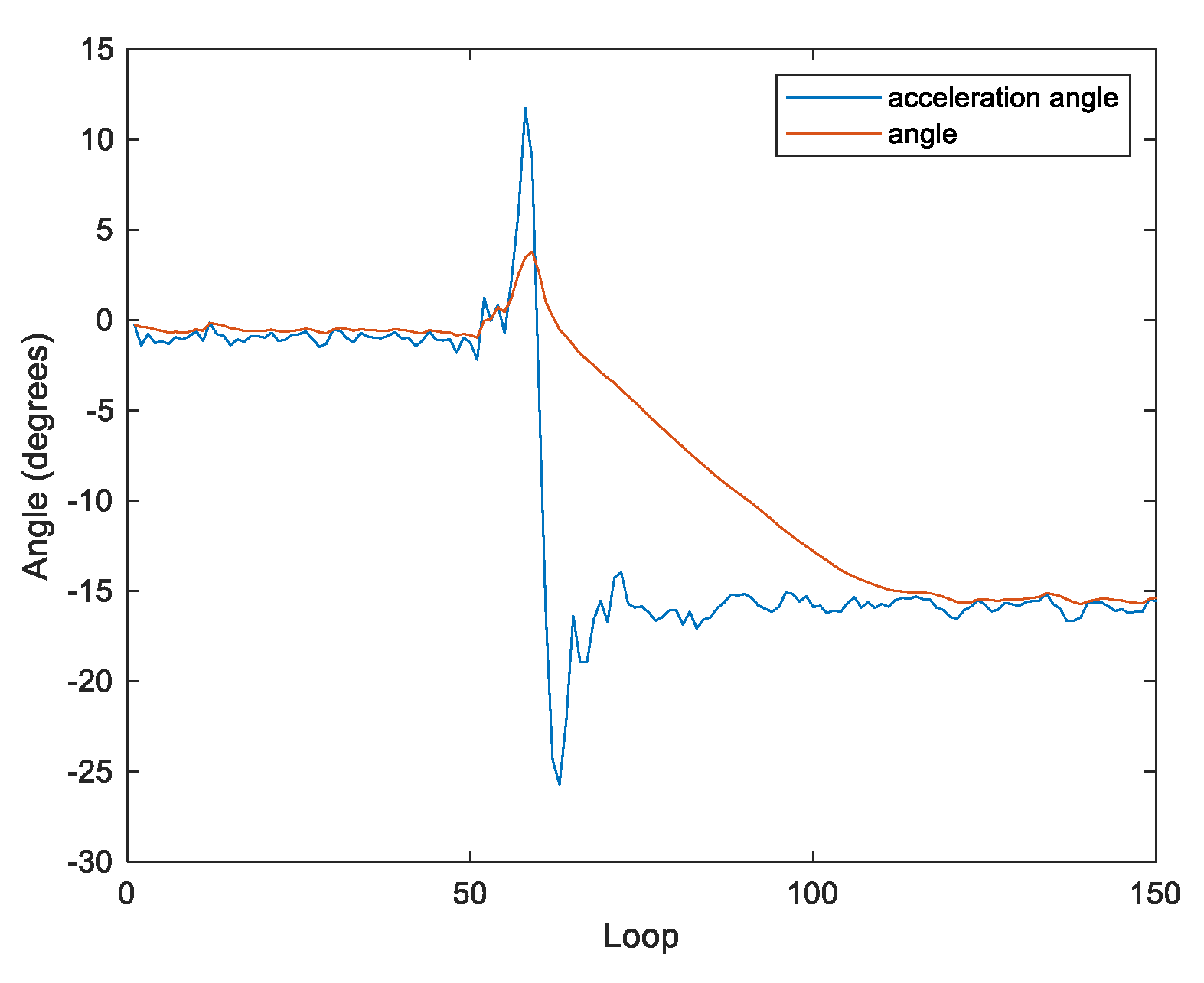
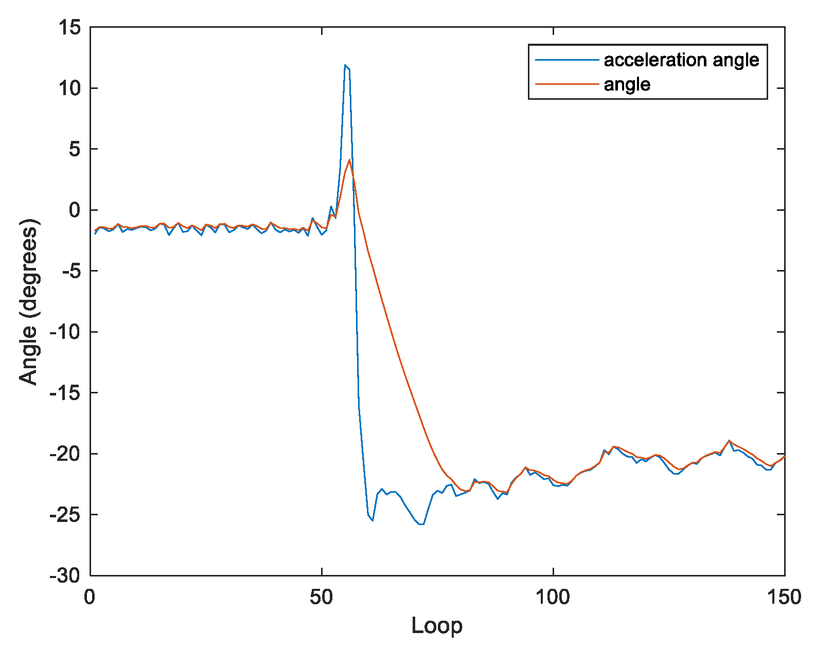
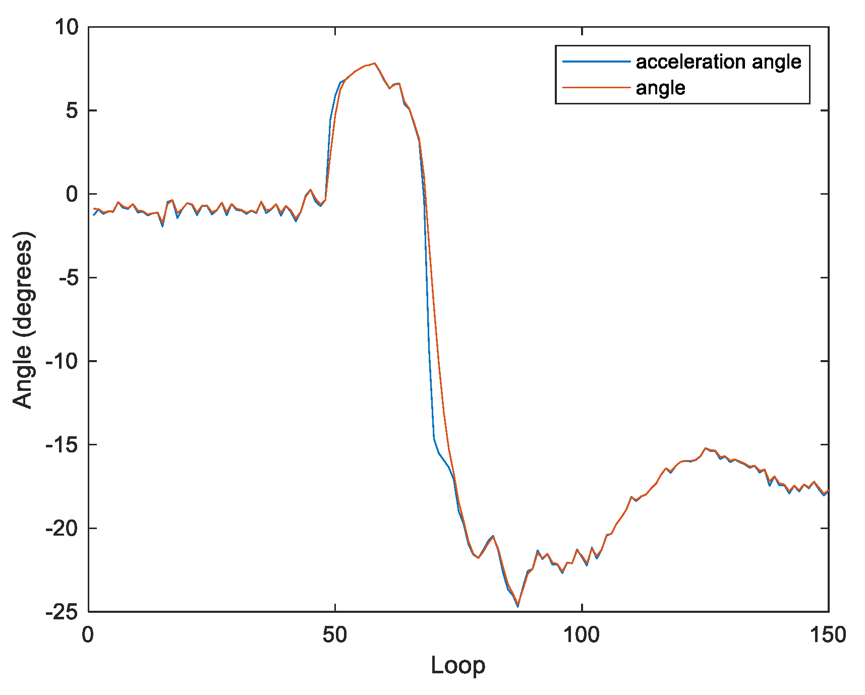
3.3. Complementary Filter
3.3.1. Traditional Complementary Filter
3.3.2. Adaptive Complementary Filter
3.4. Conventional PID Controller
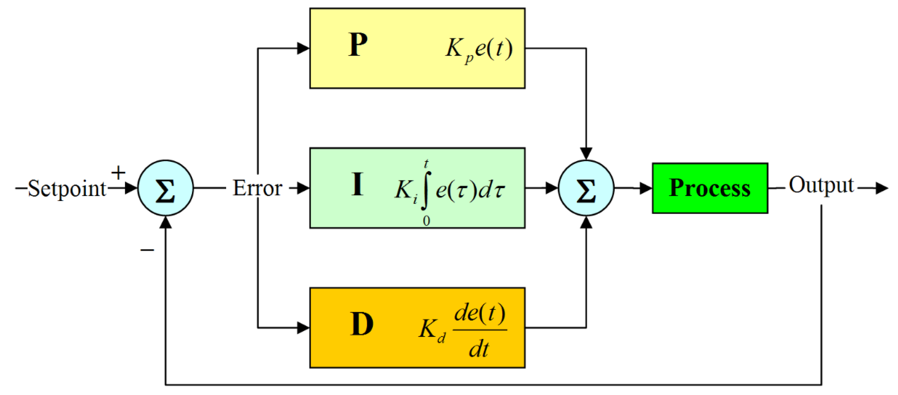
3.4.1. PID Controller
3.4.2. The Ziegler–Nichols Method
3.4.3. Tyreus–Luyben Method
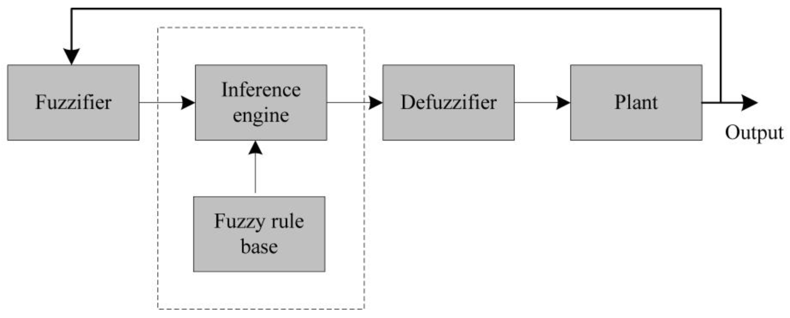
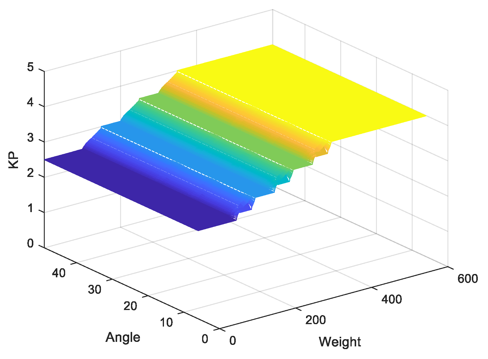
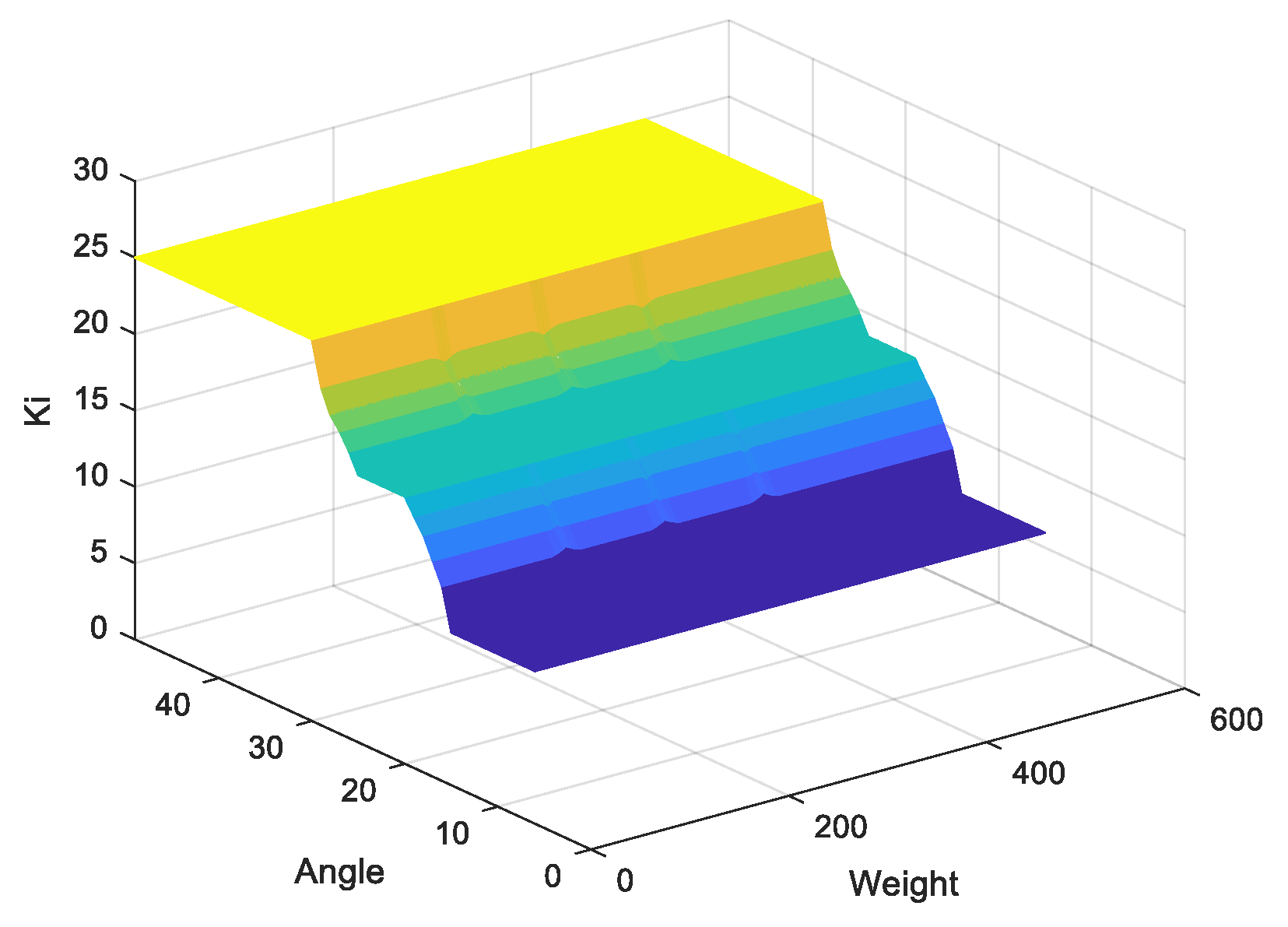
3.5. PID Controller Using Fuzzy Logic
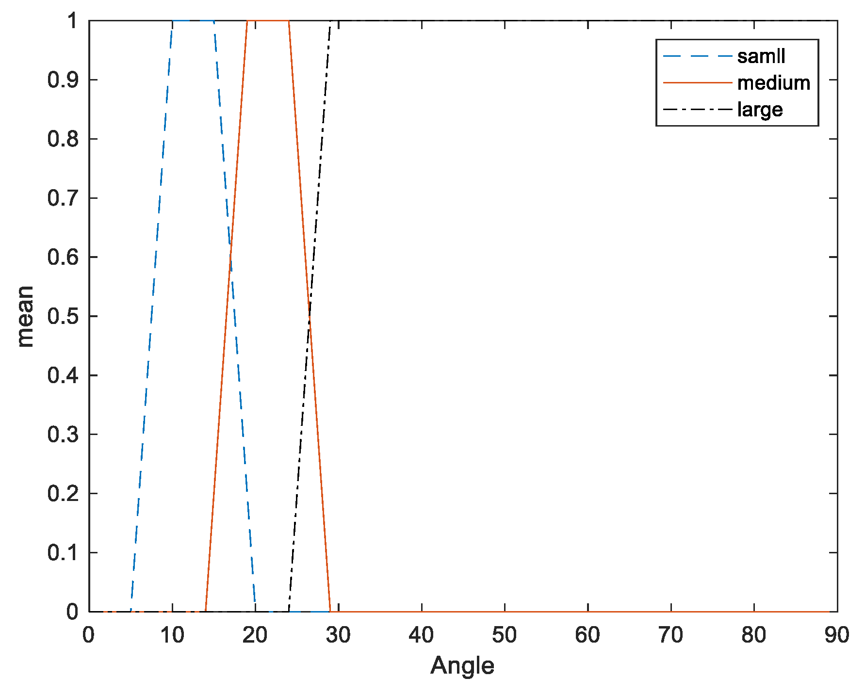
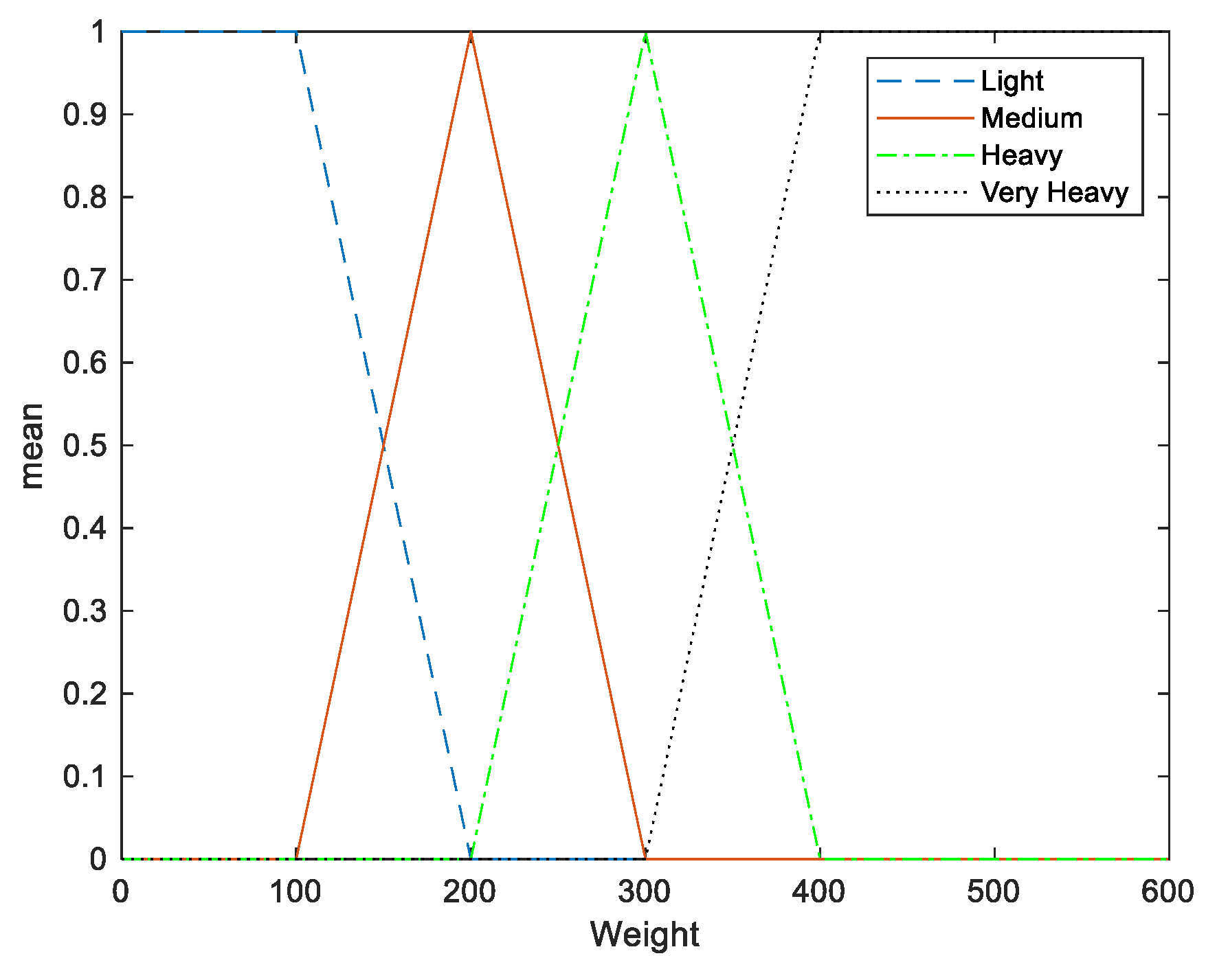
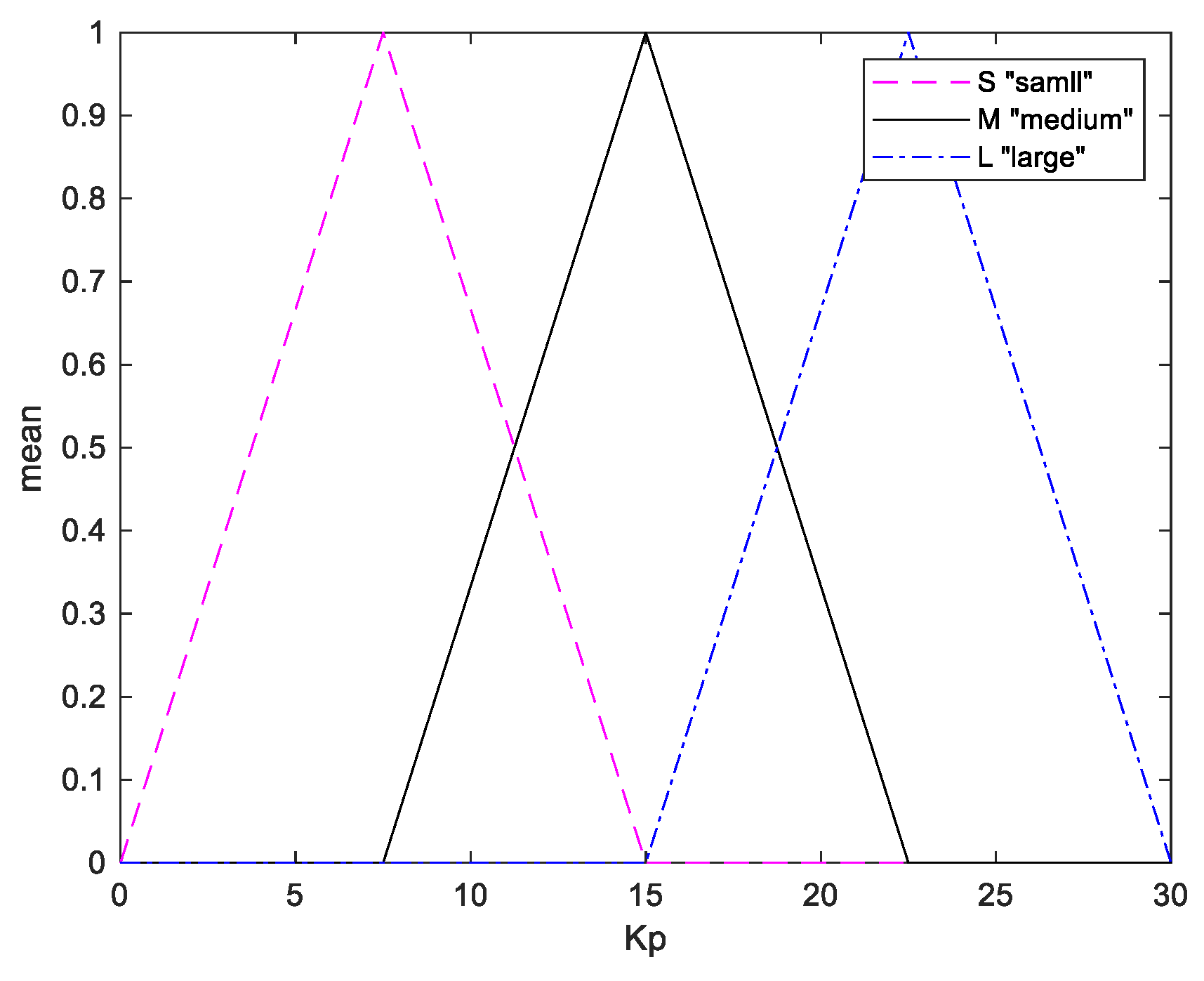
3.5.1. Fuzzification
3.5.2. Fuzzy Inference
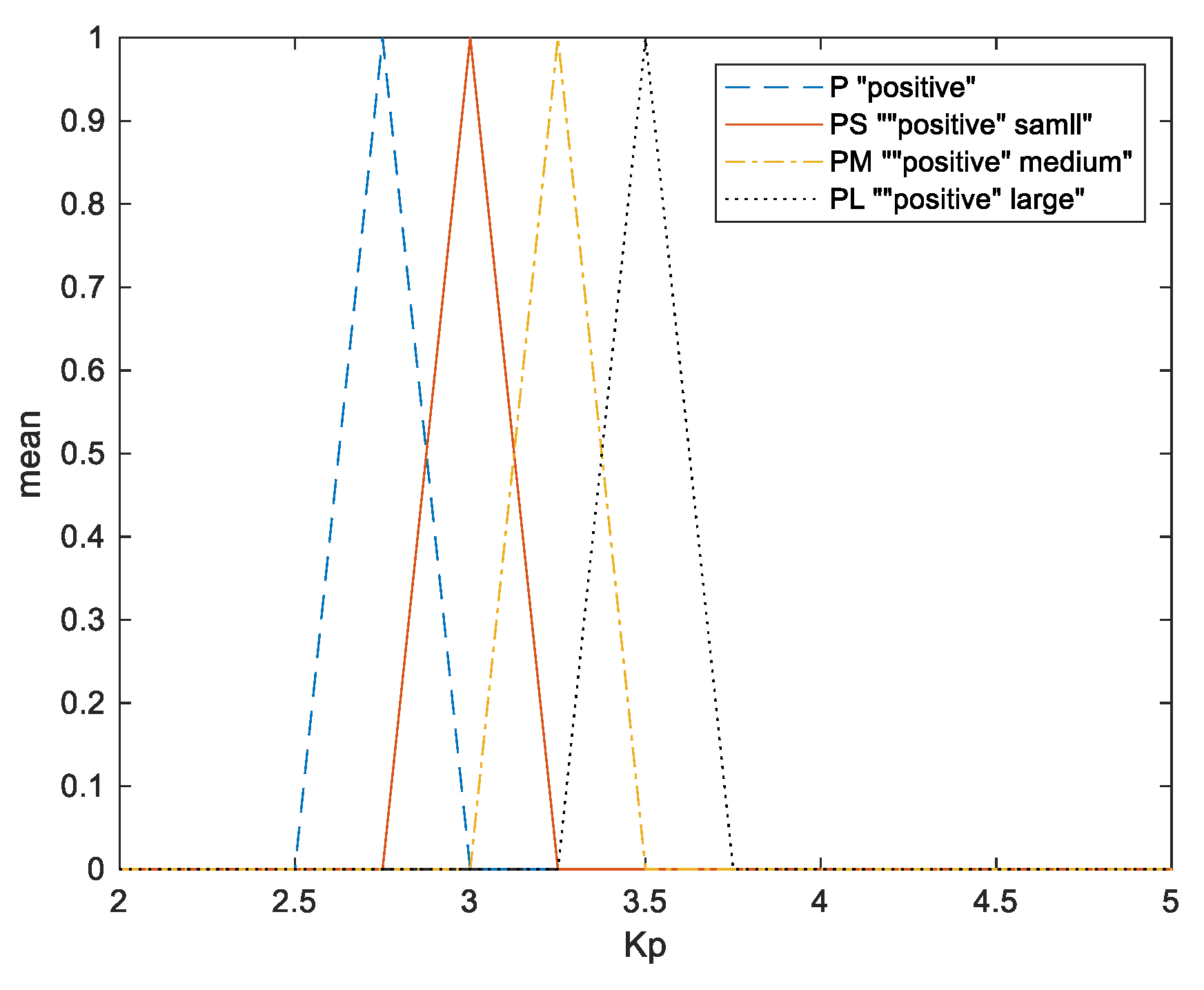
3.5.3. Defuzzification
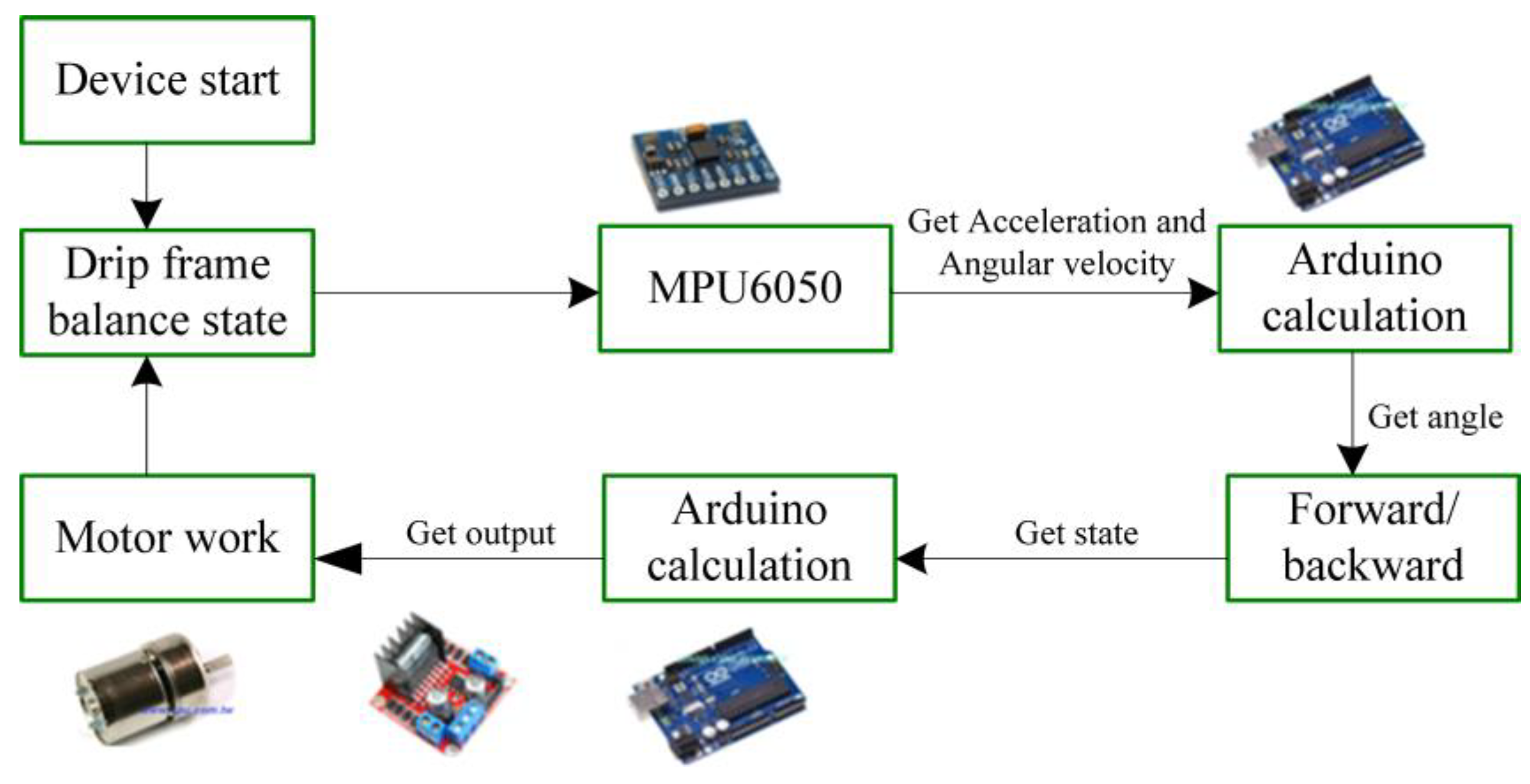
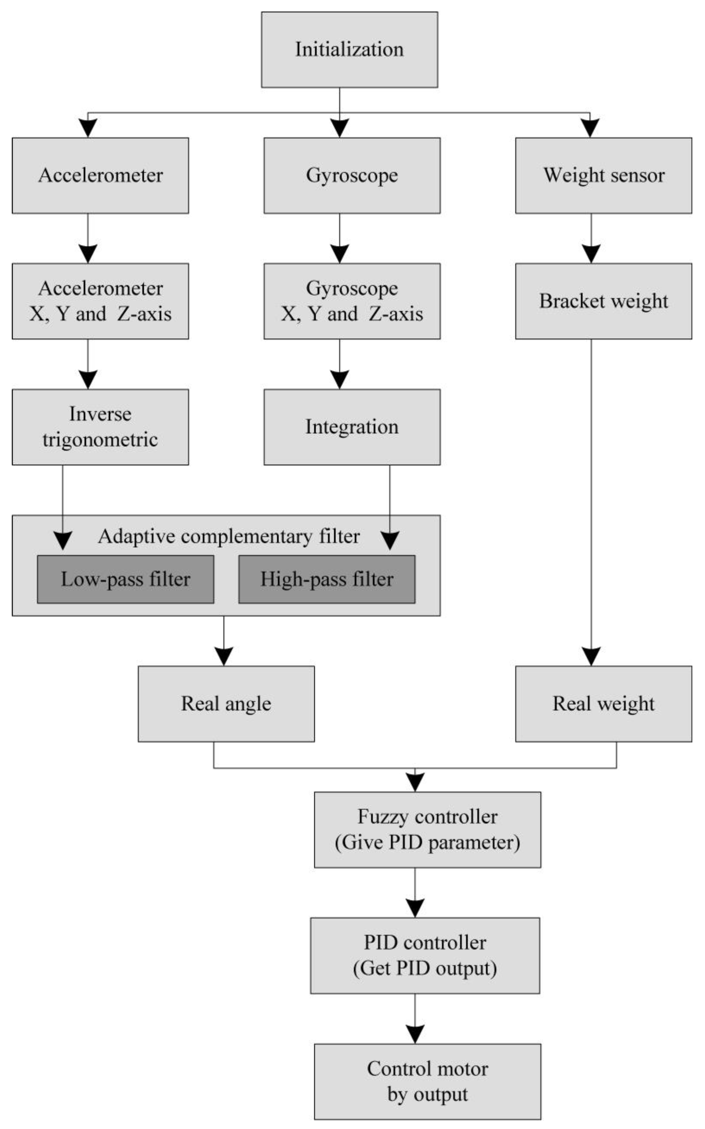
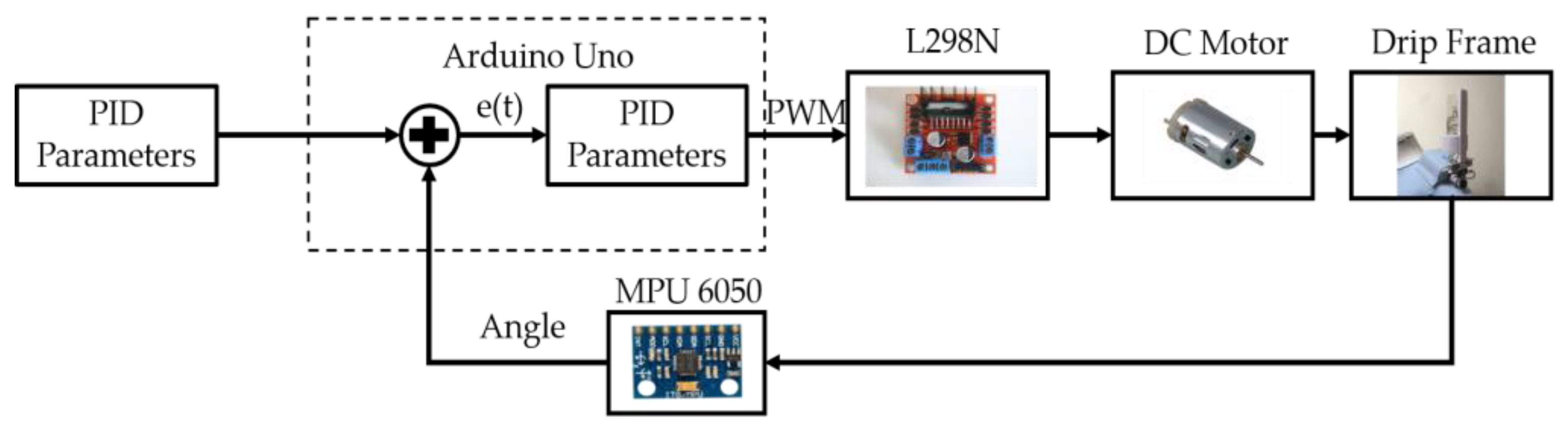
3.6. System Workflow
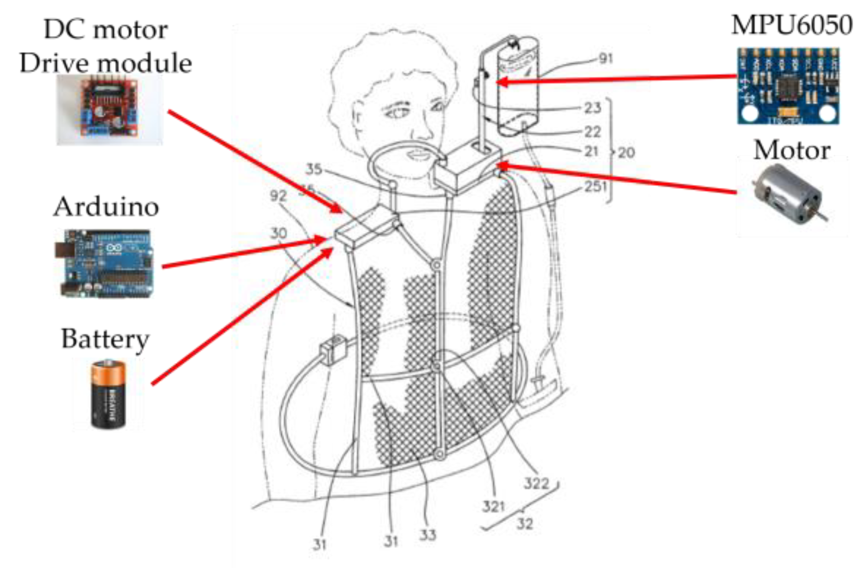
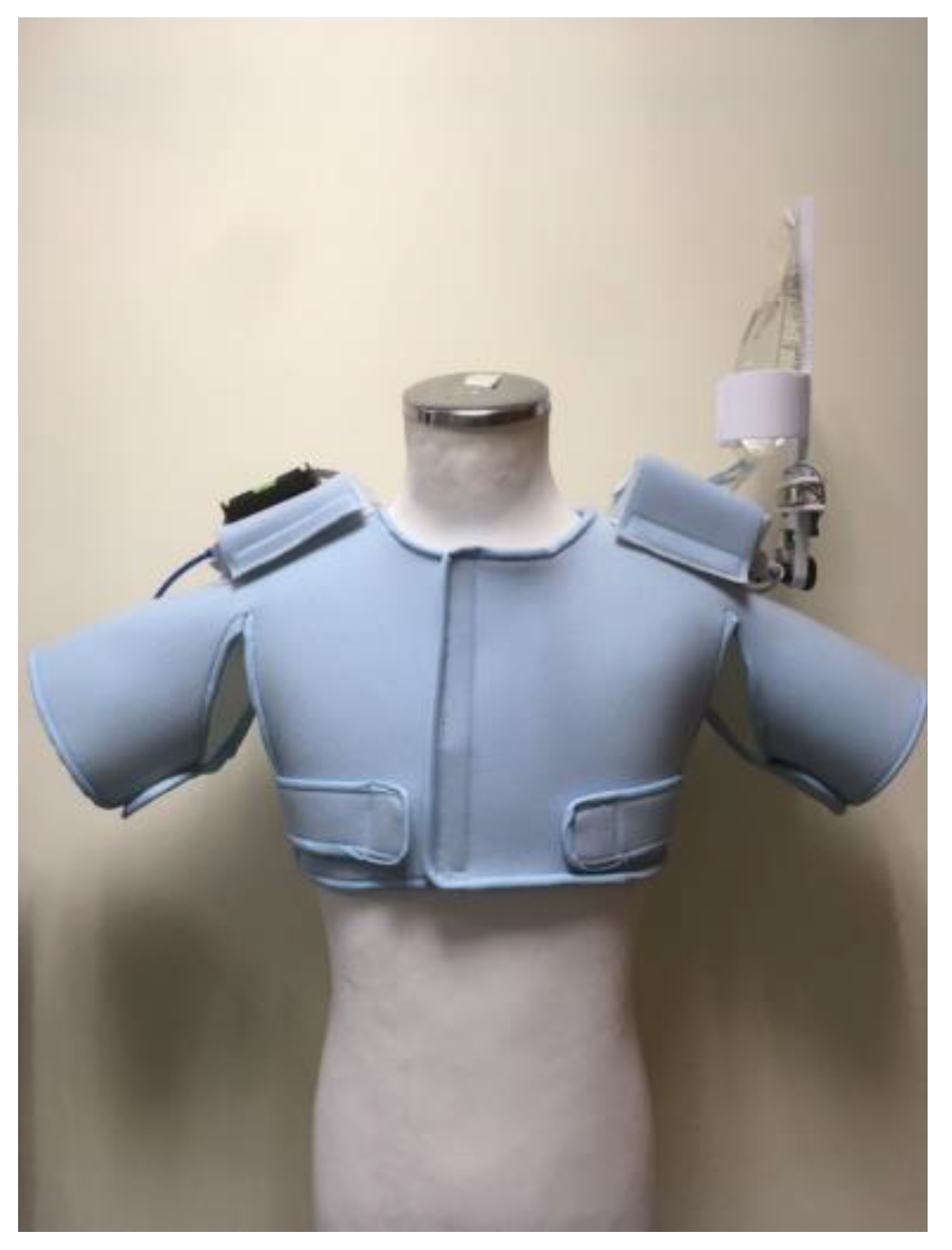
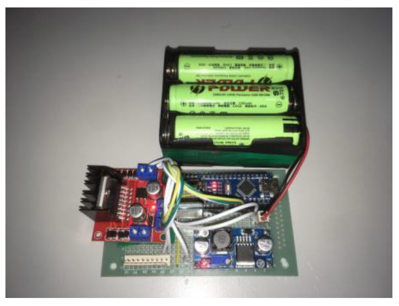
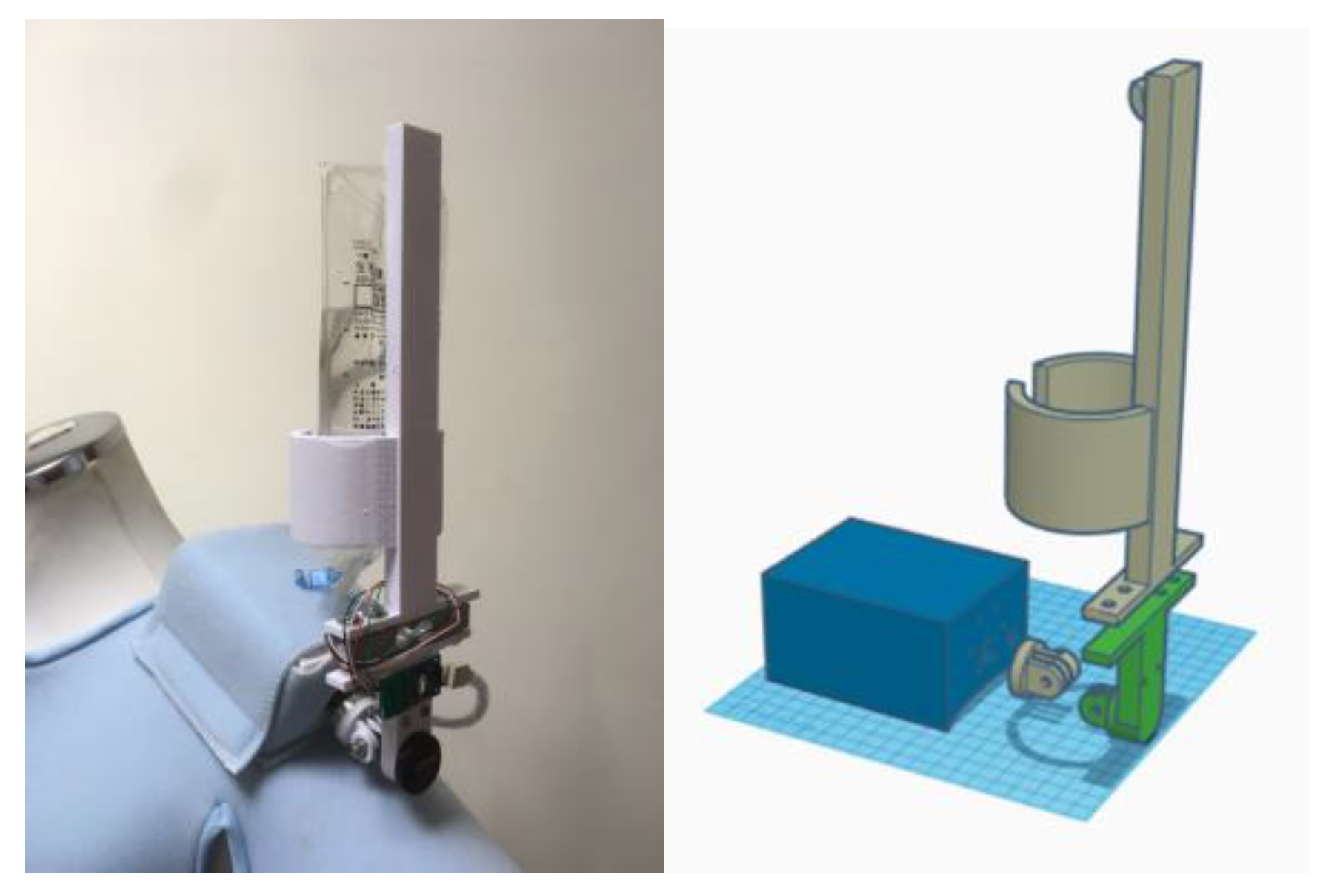
3.7. System Prototype
3.8. System on the Right Shoulder
3.9. System on the Left Shoulder
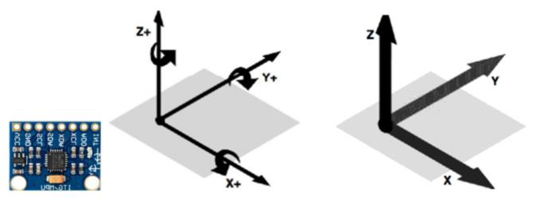
3.9.1. MPU6050
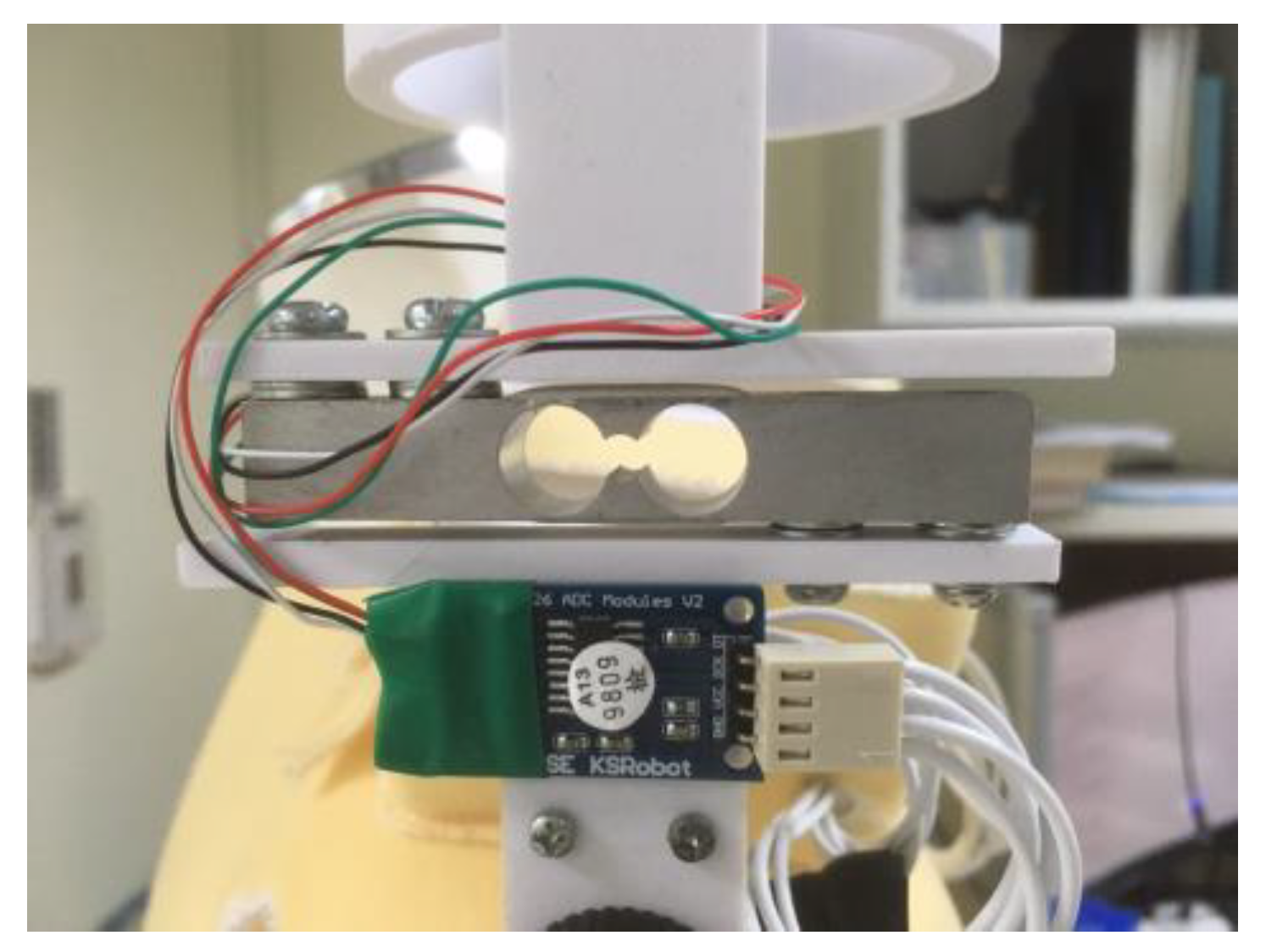
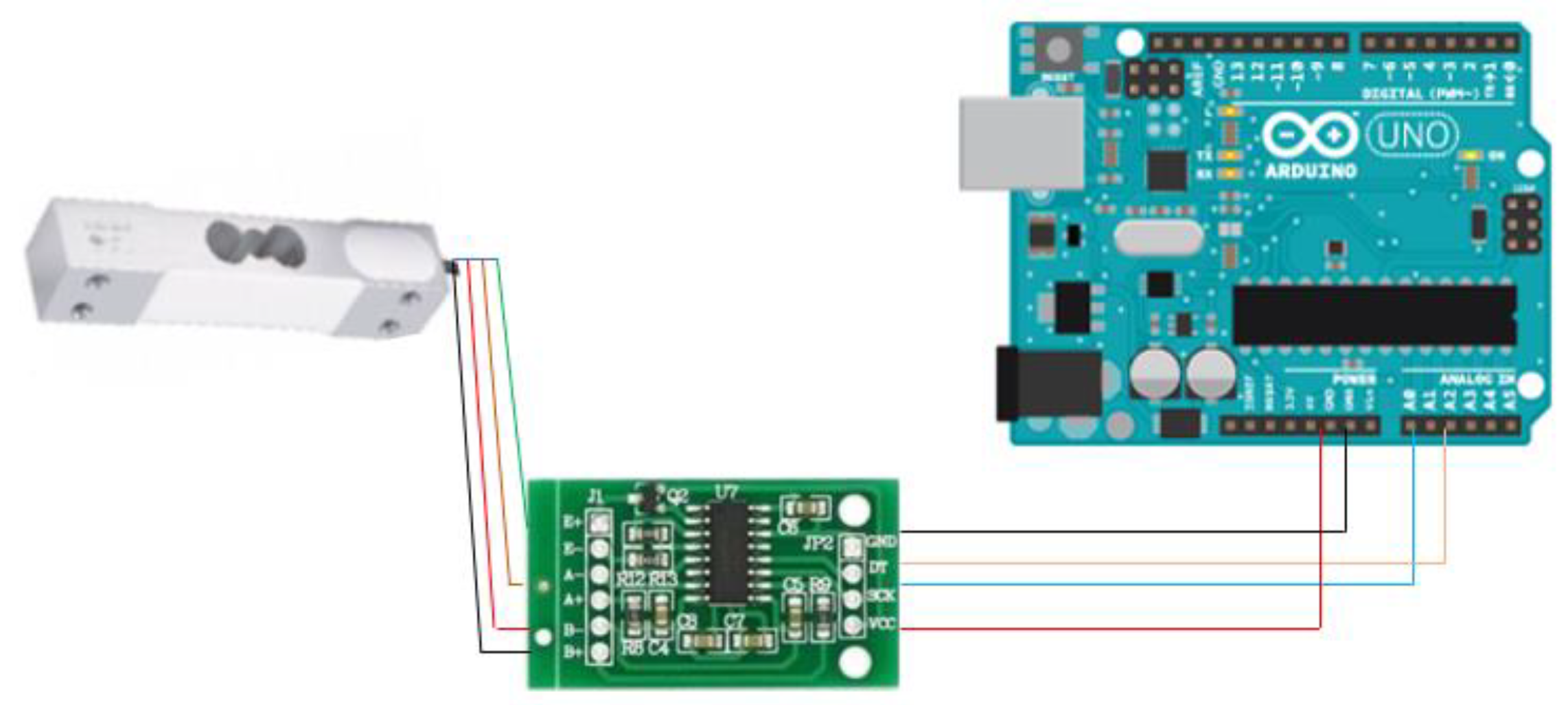
3.9.2. HX711 Electronic Scales
3.9.3. DC Motor
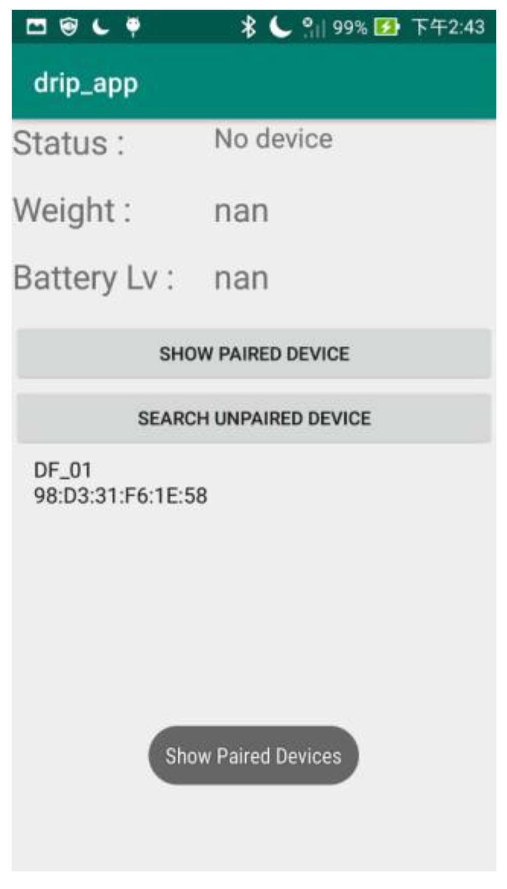
3.10. Android Application
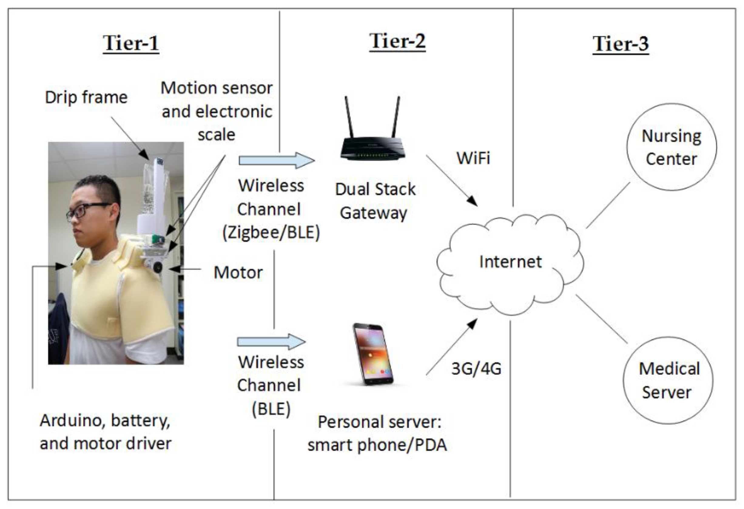
3.11. Communication Architecture
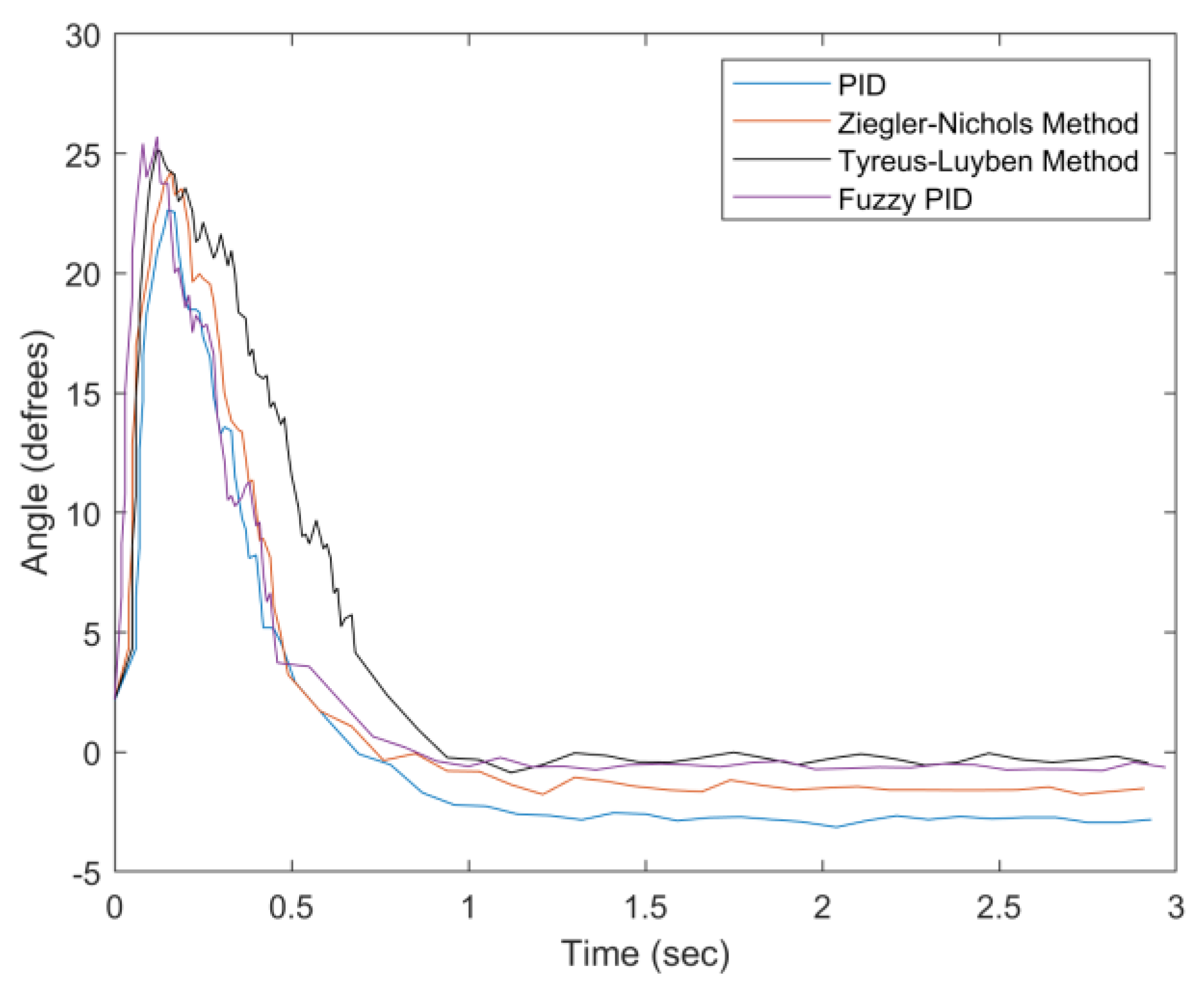
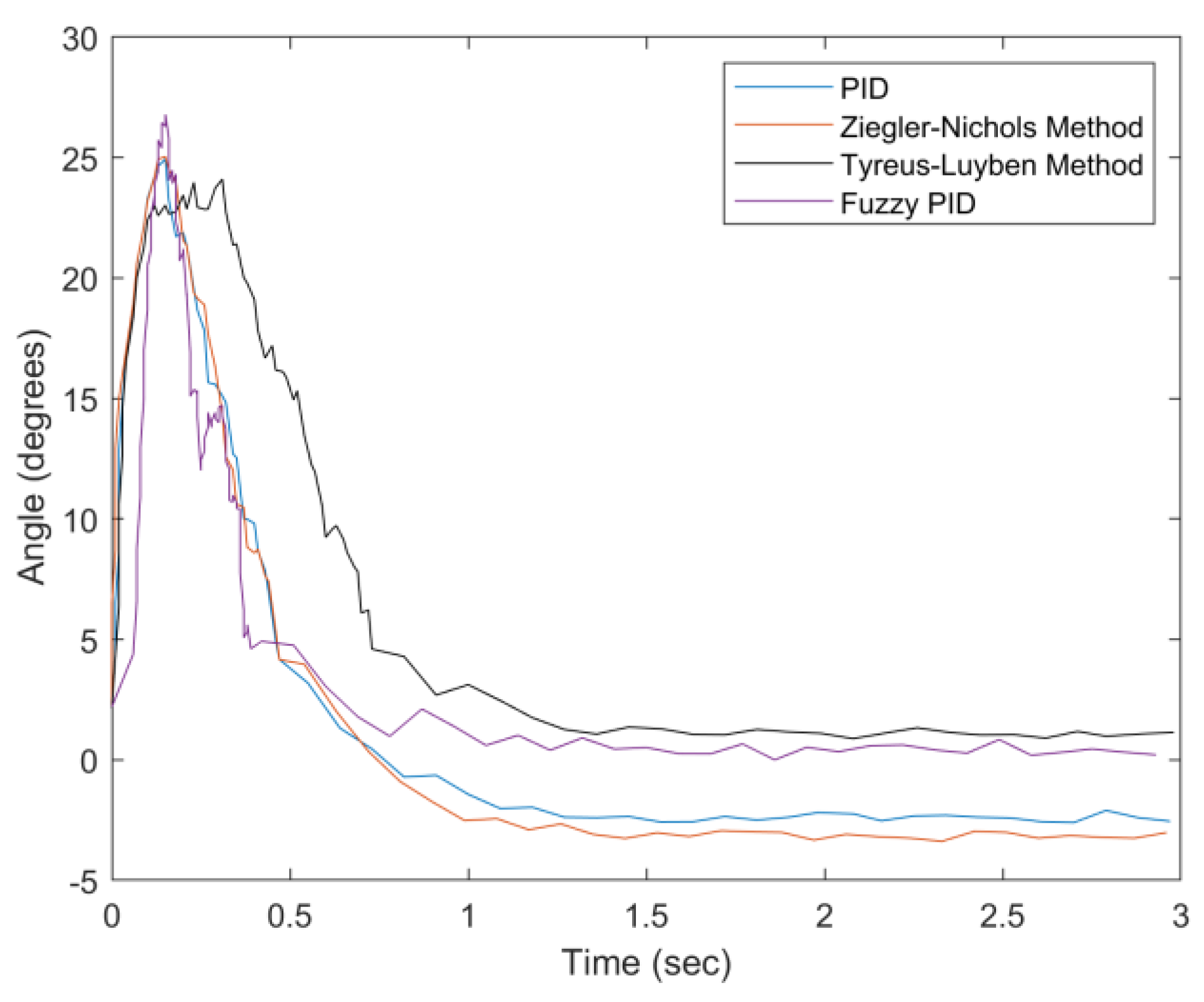
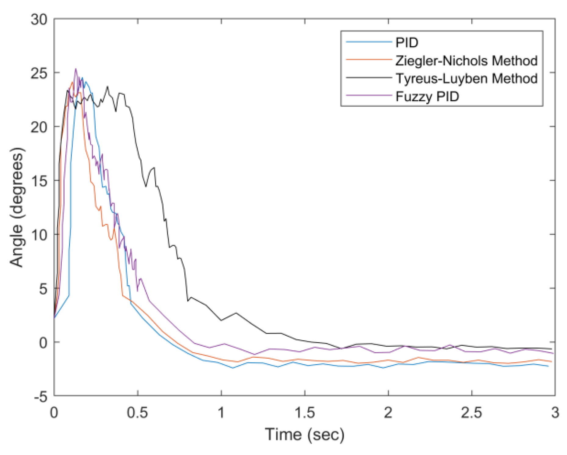
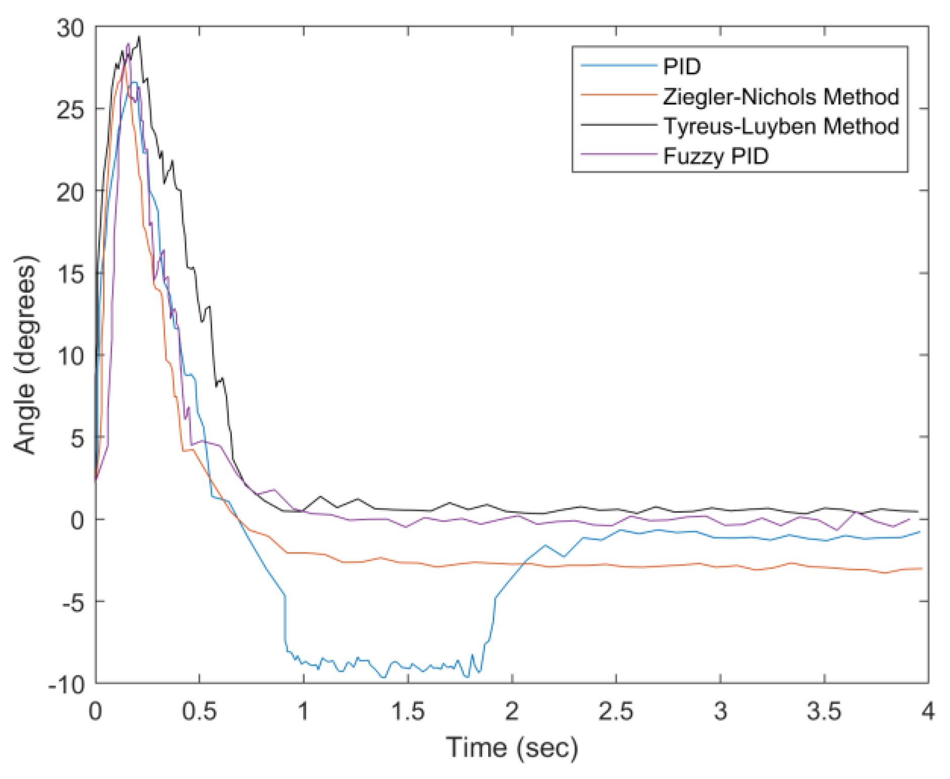
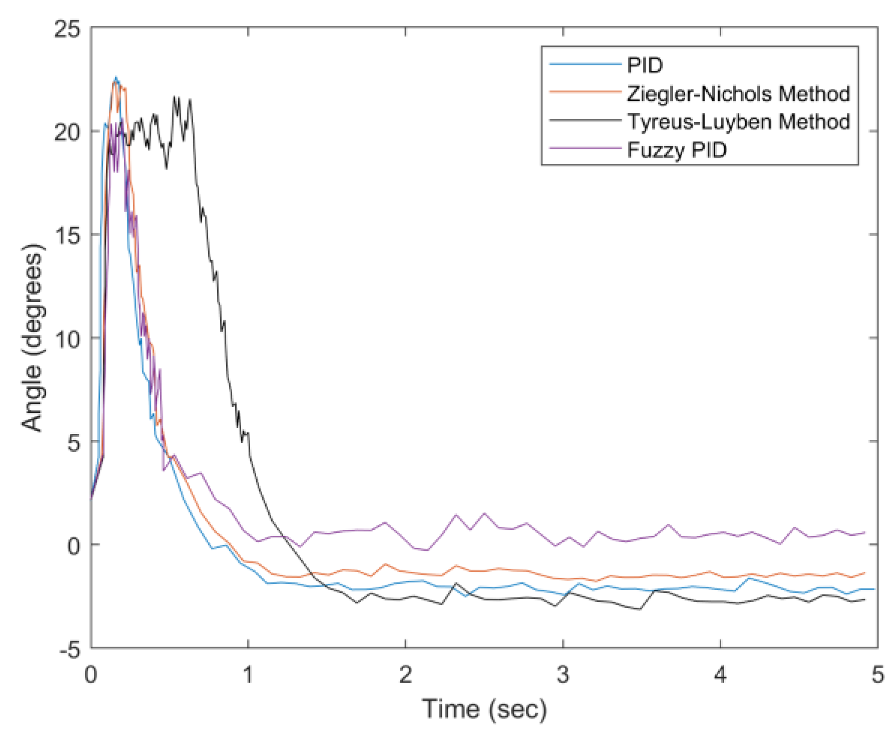
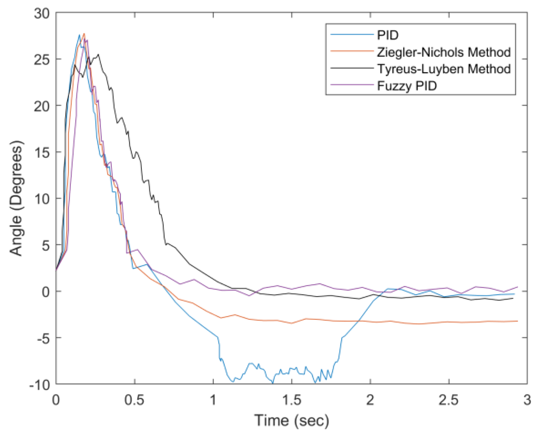
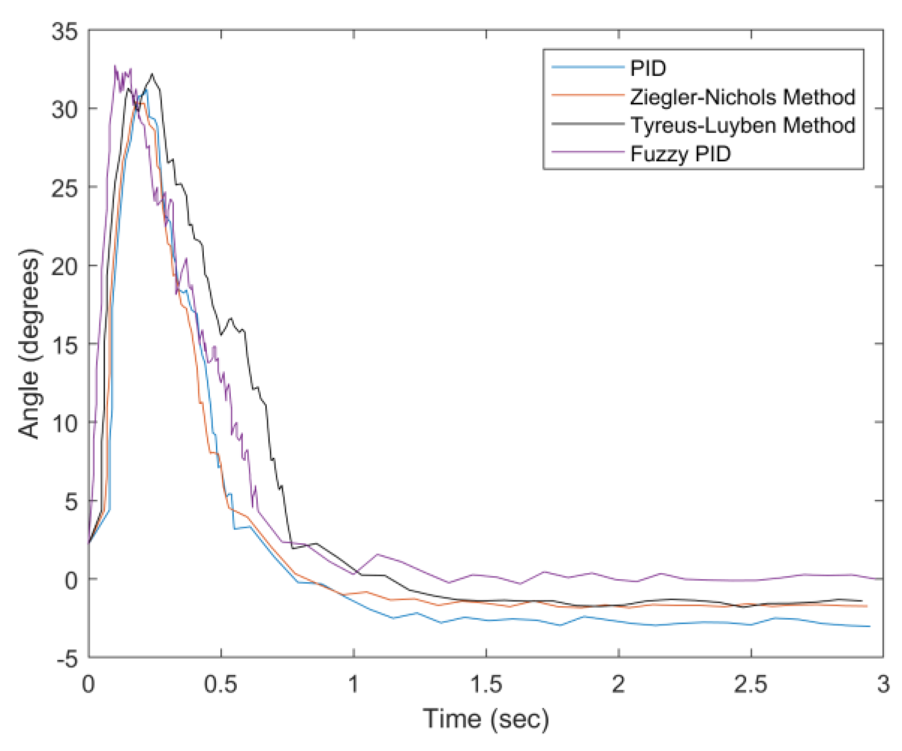
4. Results
Performance Comparison
- Percentage Overshoot/Undershoot: Referring to the ratio of the value of angle overshoot/undershoot to the maximum angle deviation, with respect to the set point:where the set point is the tilt angle of zero degrees, min Dvi is defined as the value of the overshoot/undershoot, and max Dvi is defined as the absolute value of the tilt angle.
- Settling Time: The time required for balancing the system with a tilt angle, which deviates from the set point less than 5°.
- Steady-State Error: The difference between the set point and the average tilt angle after system stabilization.
5. Conclusions
Founding
Author Contributions
Conflicts of Interest
References
- Cannon, T.; Choi, J. Development of a Segmental Bioelectrical Impedance Spectroscopy Device for Body Composition Measurement. Sensors 2019, 19, 4825. [Google Scholar] [CrossRef] [PubMed] [Green Version]
- Lin, Y.P.; Chen, T.Y.; Chen, W.J. Cost-efficient and Custom Electrode-holder Assembly Infrastructure for EEG Recordings. Sensors 2019, 19, 4273. [Google Scholar] [CrossRef] [PubMed] [Green Version]
- Massaroni, C.; Lo Presti, D.; Formica, D.; Silvestri, S.; Schena, E. Non-Contact Monitoring of Breathing Pattern and Respiratory Rate via RGB Signal Measurement. Sensors 2019, 19, 2758. [Google Scholar] [CrossRef] [PubMed] [Green Version]
- Recek, C. Venous pressure gradients in the lower extremity and the hemodynamic consequences. Vasa 2010, 39, 292–297. [Google Scholar] [CrossRef] [PubMed]
- Duh, F.C.; Chao, S.Y.; Chiu, Y.H. An Innovative Assist Device for Intravenous Infusion. Int. J. Emerg. Technol. Adv. Eng. 2015, 5, 12. [Google Scholar]
- Wu, M.F.; Chen, C.S.; Chen, I.S.; Wen, C.Y. Carryable and Automatically Balanced Intravenous Drip Frame and Using Method Thereof. In Proceedings of the 27th Annual Wireless and Optical Communications Conference, Hualien, Taiwan, 30 April–1 May 2018. [Google Scholar]
- Wu, M.F.; Wen, C.Y. Carryable and Automatically Balanced Intravenous Drip Frame and Using Method Thereof. Taiwan Patent (Invention No. I480075), April 2015. [Google Scholar]
- Kang, M.W.; Jung, S.M.; Jo, Y.R.; Choi, S.-H.; Suh, S.-H. Development of Portable Ringer’s Solution Injection Apparatus. Proceedings of the Korean Society of Mechanical Engineers, November 2014; 1718–1719. [Google Scholar]
- Duh, F.C.; Hsu, K.H.; Huang, T.K. A Portable Intravenous Injection Device. ROC Patent (Invention No. I522137), February 2016. [Google Scholar]
- Ziegler, J.G.; Nichols, N.B. Optimum Settings for Automatic Controllers. Trans. ASME 1942, 64, 759–768. [Google Scholar] [CrossRef]
- Tyreus, B.D.; Luyben, W.L. Tuning PI Controllers for Integrator/Dead Time Processes. Ind. Eng. Chem. Res. 1992, 31, 2625–2628. [Google Scholar] [CrossRef]
- Nu-Drip Wearable Dripping Bag. 2015. Available online: https://ifworlddesignguide.com/entry/185161-nu-drip (accessed on 30 January 2020).
- Shoulder-Mounted Multifunctional Hanging Device Having a Body-Fitting Structure, WO2013051887A2 (WO Application). 2013. Available online: https://patents.google.com/patent/WO2013051887A2/en (accessed on 30 January 2020).
- Liang, Z.A. A Portable Intravenous Injection Device. ROC Patent (Utility No. M404714), June 2011. [Google Scholar]
- Shu, W.S. Shoulder-mounted drip frame. ROC Patent (Utility No. M360702), July 2009. [Google Scholar]
- EZPole, Mobiu Corporation. The 30th International Medical & Hospital Equipment Show. (KIMES 2014). March 2014. [Google Scholar]
- Chang, J.W. Portable intravenous drip pressurization injection device. ROC Patent (Utility No. M368452), November 2009. [Google Scholar]
- Saleta, M.E.; Tobia, D.; Gil, S. Experimental study of Bernoulli’s equation with lose. Am. J. Phys. 2005, 73, 598–602. [Google Scholar] [CrossRef]
- Pititeeraphab, Y.; Jusing, T.; Chotikunnan, P. The Effect of Average Filter for Complementary Filter and Kalman Filter Based on Measurement Angle. In Proceedings of the 9th Biomedical Engineering International Conference (BMEiCON), Laung Prabang, Laos, 7–9 December 2016. [Google Scholar]
- Euston, M.; Coote, P.; Mahony, R.; Kim, J.; Hamel, T. A complementary filter for attitude estimation of a fixed-wing UAV. In Proceedings of the 2008 IEEE/RSJ International Conference on Intelligent Robots and Systems, Nice, France, 22–26 September 2008; pp. 22–26. [Google Scholar]
- Yoo, T.S.; Hong, S.K.; Yoon, H.M.; Park, S. Gain-Scheduled Complementary Filter Design for a MEMS Based Attitude and Heading Reference System. Sensors 2011, 11, 3816–3830. [Google Scholar] [CrossRef] [PubMed]
- Zhao, J.W.; Ruan, X.G. Modeling and Control of a Flexible Two-wheel Upright Self-balance Humanoid Robot. Robot 2009, 31, 179–186. [Google Scholar]
- Chen, W.; Yan, W.J.; Zhou, C.Y.; Du, Z.J. Control system design of two wheels self-balance robo. Transducer Microsyst. Technol. 2008, 27, 117–120. [Google Scholar]
- Zribi, A.; Chtourou, M.; Djemel, D. A New PID Neural Network Controller Design for Nonlinear Processes. J. Circuits Syst. Comput. 2015. [Google Scholar] [CrossRef] [Green Version]
- Passino, K.M.; Yurkovich, S. Fuzzy Control; Menlo Park: Addison-Wesley, CA, USA, 1997. [Google Scholar]
- David, M. Modeling the dynamically tuned gyroscope in support of high-bandwidth capture loop design. Proc. SPIE 3692 Acquis. Track. Point. XIII 1999. [Google Scholar]
- Gauss, C.F. The Intensity of the Earth’s Magnetic Force Reduced to Absolute Measurement (PDF). 1832; Retrieved 2009-10- 21. [Google Scholar]
- Vishal, G.N.; Mohammed Kashif, M.; Rahul, S.A. Portable Weight Measuring Instrument. In Proceedings of the International Conference on Recent Trends in Electrical, Electronics and Computing Technologies (ICRTEECT), Warangal, Telangana, India, 30–31 July 2017; pp. 30–31. [Google Scholar]
- Mohammed, E.; Telbany, E. Tuning PID Controller for DC Motor: An Artificial Bees Optimization Approach. Int. J. Comput. Appl. 2013, 18–21. [Google Scholar]


| Type | Advantages | Disadvantages |
|---|---|---|
| Fixed drip frame, including pulleys | Moderate convenience of movement | Lack of agility and convenience of movement |
| A shoulder-mounted drip frame (e.g., Taiwan Patents M404714 [14] and M360702 [15], EZPole [16]) | Convenience of movement |
|
| The proposed system (balanced control) |
| Equipped with a control system |
| Controller | Kp | τi | τd |
| P | 0.5Ku | - | - |
| PI | 0.45Ku | Pu/1.2 | - |
| PID | 0.6Ku | Pu/2 | Pu/8 |
| Controller | Kp | τi | τd |
| PI | Ku/3.2 | 2.2Pu | - |
| PID | Ku/3.2 | 2.2Pu | Pu/6.3 |
| Weight | Angle | ||
|---|---|---|---|
| Small | Medium | Large | |
| Light | Kp = P Ki = S | Kp = P Ki = M | Kp = P Ki = L |
| Medium | Kp = PS Ki = S | Kp = PS Ki = M | Kp = PS Ki = L |
| Heavy | Kp = PM Ki = S | Kp = PM Ki = M | Kp = PM Ki = L |
| Very heavy | Kp = PL Ki = S | Kp = PL Ki = M | Kp = PL Ki = L |
| Nominal Voltage (V) | 24 |
| Rated Power (W) | 10 |
| No Load Speed (RPM) | 15 |
| Rated Speed (RPM) | 13 |
| Rated Torque (Kg*cm) | 13 |
| Stall Torque (Kg*cm) | 78 |
| Weight (g) | 215 |
| Sample Time Interval (sec) | 0.003 |
| System Dead Zone (degree) | 5 |
| R | 2 |
| Ku | 9 |
| Pu | 0.5 |
| Weight | 100 g | 150 g | 200 g | |||
|---|---|---|---|---|---|---|
| Method | PU | ST | PU | ST | PU | ST |
| PID Controller | 9.5% | 0.55 | 9.4% | 0.46 | 33.1% | 1.92 |
| Ziegler–Nichols | 11.5% | 0.47 | 9.3% | 0.42 | 9.4% | 0.42 |
| Tyreus–Luyben | -- | 0.73 | 2.0% | 1.02 | -- | 0.66 |
| Fuzzy PID | 5.7% | 0.5 | 1.0% | 0.54 | 0.2% | 0.46 |
| Weight | 0 g | 100 g | 150 g | 200 g | |
|---|---|---|---|---|---|
| Method | |||||
| PID Controller | 2.94° | 2.36° | 2.12° | 1.28° | |
| Ziegler–Nichols | 1.33° | 2.99° | 1.77° | 2.84° | |
| Tyreus–Luyben | 0.32° | 1.11° | 0.95° | 0.6° | |
| Fuzzy PID | 0.57° | 0.53° | 0.71° | 0.11° | |
| Angle | 20° | 25° | 30° | |||
|---|---|---|---|---|---|---|
| Method | PU | ST | PU | ST | PU | ST |
| PID Controller | 8.9% | 0.5 | 38.2% | 1.83 | 6.1% | 0.55 |
| Ziegler–Nichols | 6.9% | 0.49 | 10.3% | 0.47 | 5.5% | 0.53 |
| Tyreus–Luyben | 13.4% | 1.01 | 1.6% | 0.76 | 4.4% | 0.75 |
| Fuzzy PID | -- | 0.46 | -- | 0.45 | -- | 0.64 |
| Angle | 20° | 25° | 30° | |
|---|---|---|---|---|
| Method | ||||
| PID Controller | 2.06° | 0.24° | 1.47° | |
| Ziegler–Nichols | 1.41° | 3.25° | 1.63° | |
| Tyreus–Luyben | 2.60° | 0..51° | 1.41° | |
| Fuzzy PID | 0.53° | 0.23° | 0.21° | |
© 2020 by the authors. Licensee MDPI, Basel, Switzerland. This article is an open access article distributed under the terms and conditions of the Creative Commons Attribution (CC BY) license (http://creativecommons.org/licenses/by/4.0/).
Share and Cite
Wu, M.-F.; Chen, C.-S.; Chen, I.-S.; Kuo, T.-H.; Wen, C.-Y.; A. Sethares, W. Design of Carryable Intravenous Drip Frame with Automatic Balancing. Sensors 2020, 20, 793. https://doi.org/10.3390/s20030793
Wu M-F, Chen C-S, Chen I-S, Kuo T-H, Wen C-Y, A. Sethares W. Design of Carryable Intravenous Drip Frame with Automatic Balancing. Sensors. 2020; 20(3):793. https://doi.org/10.3390/s20030793
Chicago/Turabian StyleWu, Ming-Feng, Chia-Shan Chen, I-Shan Chen, Tz-Hau Kuo, Chih-Yu Wen, and William A. Sethares. 2020. "Design of Carryable Intravenous Drip Frame with Automatic Balancing" Sensors 20, no. 3: 793. https://doi.org/10.3390/s20030793