1. Introduction
It has been over a decade since electron spin debuted in the semiconductor device industry [
1,
2,
3]. The new field of electronics, called spintronics, harnesses the intrinsic spin of an electron and its associated magnetic moment along with its electronic charge [
4]. Spintronics has already revolutionized computer memory devices [
5]. Spintronics possesses inestimable potential for futuristic computer technology, including the development of quantum computers [
6] and combining logic and memory in the same device [
3,
7]. A significant limitation of the emerging technology is that it is based on limited traditional materials such as inorganic metals and semiconductors. Utilization of the ferromagnetic metal is essential because of the high Curie temperature required for its commercially useful applications [
2,
8]. Alloying magnetic materials and stacking multiple magnetic layers offer the possibility of obtaining various magnetic properties [
9,
10].
A new spintronics field is emerging that combines the quantum properties of the mass-producible molecule as the device element [
11,
12,
13] between two ferromagnetic electrodes [
14,
15]. Connecting molecules between two ferromagnetic electrodes opens the flood gate for innovations. Interestingly, commercially successful magnetic tunnel junction (MTJ) technology comes very close to the concept of connecting ferromagnetic electrodes with molecules as active transport channels. However, unlike MTJs, which only rely on magnesium oxide as an insulator [
10] due to MTJs desirable switching attributes [
1,
9], molecule-based spintronics has billions of types of molecules that can be included as spin channels. Molecules can be designed with useful optical, magnetic, and electrical properties. Most importantly, a desirable molecule can be mass-produced to sub-angstrom level structural precision [
16,
17,
18,
19].
Molecular spintronics devices (MSDs) can overcome the miniaturization limits and heating issues associated with existing computer technology [
20]. However, due to the nanoscale size of the molecules (∼1 nm), it is difficult to keep the molecular dimension robust and maintain a reproducible gap between the two ferromagnetic leads [
21]. To avoid these difficulties, we developed a new approach to making magnetic tunnel junction-based molecular spintronics devices (MTJMSDs). To produce an MTJMSD, the molecular channels were bridged across the insulator of an MTJ testbed with exposed side edges of the FM electrodes. MTJMSD properties and their applications are highly influenced by ferromagnetic electrodes’ physical properties, such as their various anisotropies, thermal energy, coupling of the ferromagnetic electrode atoms of two electrodes via magnetic molecules, etc. [
22]. Interestingly, we observed a remarkable difference between the on and off states in MTJMSDs [
23]. However, this observation was transient and insufficient to yield repeatable switching at room temperature.
Under the aspiration of making bistable memory devices, we experimentally realized an MTJMSD by including two multi-layered magnetic electrodes with different magnetic properties, deposited via sputtering process. Prior literature shows that the simple addition of seed layers and simply altering the sequence of thin ferromagnetic layers dramatically impact the magnetization properties of electrodes and devices [
24,
25,
26,
27,
28]. Here, we discuss experimental studies showing the impacts of various magnetic electrodes on MTJMSDs. Cross-junction-shaped MTJMSDs designed for conducting transport studies possessed long ferromagnetic electrodes. Long ferromagnetic electrodes enable the connection of molecule–ferromagnetic electrode interfaces with the outer world for transport and device attributes. However, understanding the impact of the interaction between paramagnetic molecules and long multilayered ferromagnetic electrodes was experimentally challenging. The challenge of understanding MSD is harder when ferromagnetic electrodes possess different magnetic anisotropies. It is a daunting task to understand the overall device properties of MTJMSDs experimentally when individual in-plane and out-of-plane easy-axis anisotropies are operating. Here, we also present our Monte Carlo simulations (MCSs) of an MTJMSD with extended electrodes of variable anisotropies. In the MCS study, we systematically applied the in-plane and out-of-plane anisotropies individually and together to gain an atomistic understanding of the resultant equilibrium properties.
2. Results and Discussions
The first step in exploring the effect of anisotropy on MTJMSD focused on understanding the evolution of the equilibrium state from perturbed states. For this objective, we explored the evolution of MTJMSD over time for combinations of
ALx and
ALy. Figure 1 shows the impact of anisotropies on the overall magnetic properties of MTJMSD during the energy minimization of the MCS (magnetic moment vs. iteration counts) with given in-plane and out-of-plane easy-axis anisotropies. Temporal evolutions were recorded at
kT = 0.1.
Figure 1a shows the variation in the magnetic moment of the MTJMSD as a function of iteration counts when there were no anisotropies on the left ferromagnetic electrode. Based on the dimensions of the MTJMSD used during the MCS, the left and right ferromagnetic electrodes could attain a maximum magnetic moment magnitude of 1250. At the same time, the MTJMSD’s maximum magnetic moment settled around 2516 (1250 for each ferromagnetic electrode and 16 for molecules). It is noteworthy that we kept the right electrode isotropic during the simulation. As a result, the total magnetic moment of the right FM electrode was always close to its maximum value of
1200. When
ALx = 0 and
ALy = 0 the magnetic moment of the left electrode started to increase quasi-linearly with the iteration counts before it saturated at around 250 million iterations. The magnetic moment of the left electrode saturated to its maximum value of
1150. In the absence of anisotropies, the antiferromagnetic coupling provided by the Heisenberg coupling of the left and right electrodes with the molecules was the dominating factor. The molecule coupling with electrodes was
JmR = 1 and
JmL = −1, respectively. The total magnetic moment of the MTJMSD was always lower than that of the left and right electrodes due to the opposite magnetic spins of the left and right FM electrodes (
Figure 1a). When
ALx = 0 but
ALy = 0.5, the in-plane anisotropy was forced to align the magnetic spins of the left ferromagnetic electrode and overcame the effect of
JmL (
Figure 1b). It was also observed that
ALy caused the magnetic moment to particularly align in the spin direction opposing
JmL.
As a result, the magnetic moment of the left electrode was decreased, but that of the MTJMSD increased. The impact of out-of-plane anisotropy and the competing effect of in-plane and out-of-plane anisotropy are described in
Figure 1c,d, respectively. When
ALx = 0.5 and
ALy = 0 (
Figure 1c), the impact of out-of-plane anisotropy was somewhat similar as when provided with an equal magnitude of in-plane anisotropy (
Figure 1d).
A notable observation occurred at around 175M iteration counts. At this stage, a sudden jump in the magnetic moment of the left FM electrode was observed (
Figure 1c). The sudden jump in the magnetic moment of the left FM electrode was due to the formation of the dominant magnetic phase of the same spin orientations due to the out-of-plane easy-axis anisotropy, which will be further discussed in this manuscript. The magnetic moment saturated close to ~425, immediately after the jump of the magnetic moment. With the application of in-plane and out-of-plane anisotropies on the same left ferromagnetic electrode, we observed that the effects of the anisotropies started to annihilate each other (
Figure 1d). We refer to annihilation as “competing impact” in this report. The competing impact of anisotropies produced a high value of magnetic moments by aligning all the magnetic spins of the atoms of the left electrode. However, the orientation of the magnetic spins of the left FM electrode was opposite to that of the isotropic right electrode due to strong molecule-induced antiferromagnetic coupling. Therefore, the total magnetic moment of the MTJMSD was observed to be smaller than that of the left and right electrodes. When the magnetic moments of the left and right electrodes were close to equal, but the magnetic spins of the left and right FM electrodes were opposite (~325 M iteration counts), the total magnetic moment of the MTJMSD was almost zero, as shown in
Figure 1d. The overall magnetic moment of the MTJMSD was similar when anisotropies were not applied to the left FM electrode (
Figure 1a) or when the FM electrode had an equal magnitude of in-plane and out-of-plane anisotropies (
Figure 1d). The prior case happened due to antiferromagnetic Heisenberg coupling of the left and right FM electrodes with paramagnetic molecules. In comparison, the latter case was due to the competing effect of in-plane and out-of-plane anisotropies on the left FM electrode.
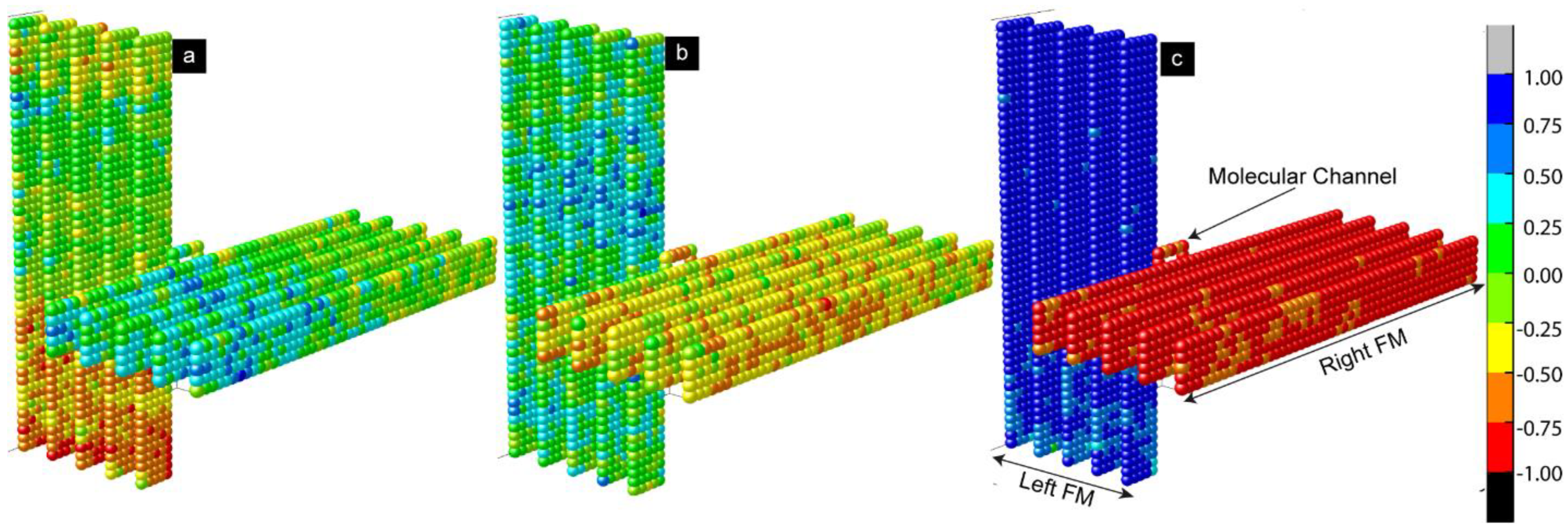
To understand the actual spin configurations of the left and right FM electrodes, we analyzed the atomic-scale equilibrium moment of the MTJMSD’s Heisenberg model (
Figure 2 and
Figure 3).
Figure 2 shows three 3D spins’ vector intensities along the x, y, and z directions. In 3D atomic schematic representation, the left FM electrode is represented by vertical lattices, while horizontal lattices represent the right FM electrode, and molecules are represented by small squares between the left and right FM electrodes. The color scale bar presented in
Figure 2 and
Figure 3 represents the normalized magnetic moment. A Monte Carlo simulation (MCS) takes the variable that has uncertainty and assigns it a random seed. The model is then run, and a result is provided. This process is repeated while assigning many different values to the variable in question. Once the simulation is complete by energy minimization, the equilibrium state magnetic moments are averaged together to provide an estimate. As a result, the settlement of the magnetic spins is always arbitrary along the x, y or z spin direction in the absence of anisotropies, as illustrated in
Figure 2. In this particular situation, the spins of the magnetic atoms settled in the z direction. The settlement of the magnetic spin direction is completely random unless we provide the same seed or apply the anisotropies during the simulations. The closeness of the color corresponding to the magnetic moment of the molecules and the first right ferromagnetic electrode occurred because the molecules created strong ferromagnetic coupling with the right electrode (
JmR = 1). On the other hand, the complete color contrast of the molecules with the left ferromagnetic electrode occurred because the molecule created antiferromagnetic coupling with the left electrode (
JmL = −1).
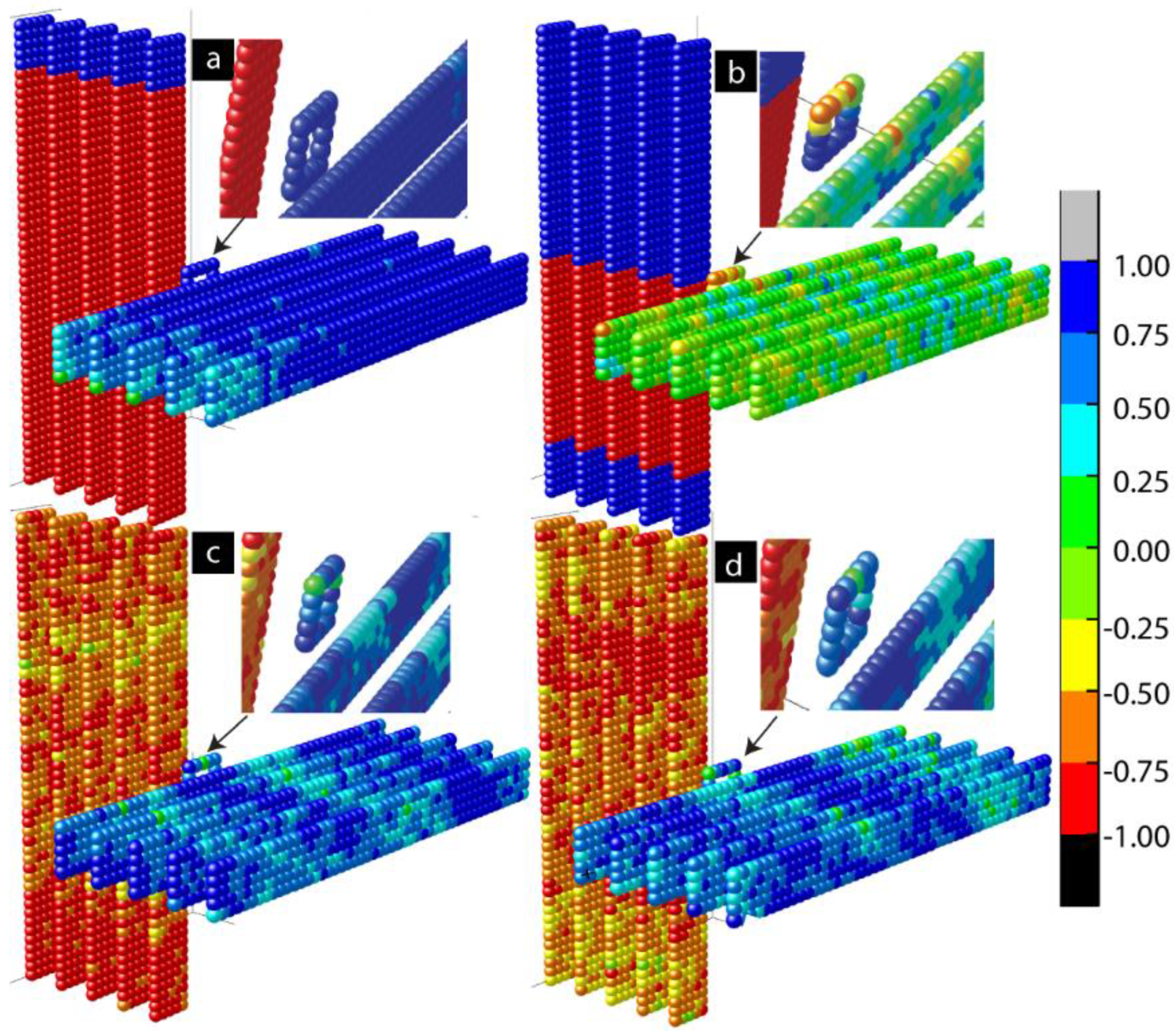
Figure 3a represents the 3D lattice model along the x spin direction when out-of-plane magnetic anisotropy
ALx = 1. Anisotropy caused the multiple magnetic domains of opposite spins that appeared on the left ferromagnetic electrode (
Figure 3a). These domains represent the different magnetic phases. With the application of strong out-of-plane anisotropy, a dominant magnetic phase appeared on the left electrode. A residual secondary magnetic phase of opposite spins also appeared, as shown in
Figure 3a. The effect of anisotropy appeared on the left ferromagnetic electrode and transferred to the right ferromagnetic electrode via molecular channels. As a result, ordered magnetic spins states appeared on the right electrode despite not having any anisotropies on the right FM electrode (
ARx = ARy = 0). The spin orientation of the right FM electrode was opposite to that of the left FM electrode, despite the spin stabilization that happened on the right FM electrode due to the left FM electrode. The molecules maintained the antiferromagnetic couplings with the left FM electrode, represented by opposite spin colors (red and blue for the left FM electrode and molecules, respectively). Since the molecular exchange coupling was transferring the impact to the right FM electrode via molecular channels, the spin orientation of the right FM electrode aligned itself to the molecules’ spin directions. The application of in-plane anisotropy (
ALy = 1) caused multiple magnetic phases of opposite magnetic spins, as shown in
Figure 3b. Unlike out-of-plane anisotropy, there was no dominant magnetic phase. Molecular channels were connected on the left electrode in the boundary region of two phases of opposite spins, as shown in
Figure 3b. As a result, the effect of anisotropy appearing on the left electrode could not be transferred to the right electrode. When
ALx = ALy = 1, the competing impact of in-plane and out-of-plane anisotropies were observed on the electrode, as shown in
Figure 3c,d. When we carefully observed the 3D lattice,
Figure 3c, slightly more red spots appeared on the left electrode. This is because the net magnetic moment caused by the dominant magnetic phase on the left electrode was not destroyed due to the competing impact.
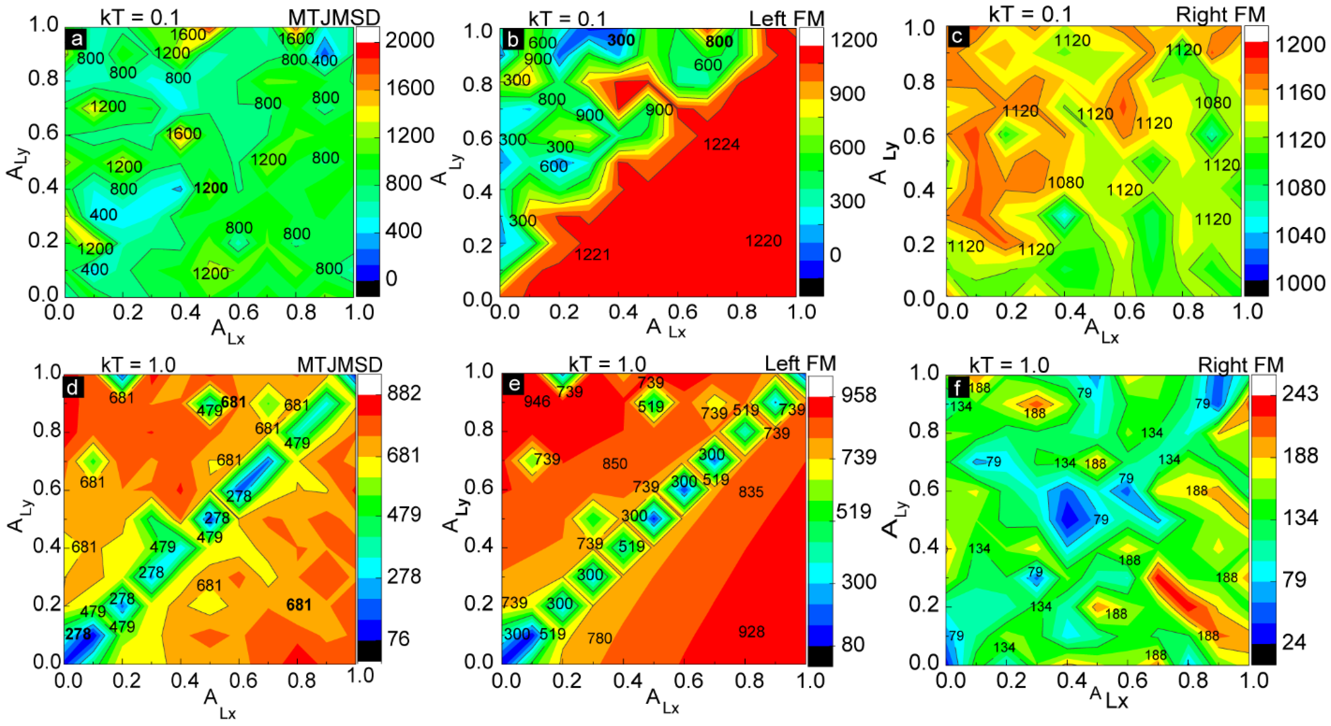
We also investigated the effect of thermal energy (
kT) on the MTJMSD for various combinations of anisotropies.
Figure 4 represents the magnitude of the magnetic moment measured continuously as a function of anisotropy at constant thermal energies. We varied the thermal energy
kT from 0.1 to 1. Thermal energy
kT = 0.1 was near room temperature with the assumption that the Curie temperature of the MTJMSD varied with the FM electrode from 300 °C to 800 °C.
Figure 4a represents the contour plot for the magnetic moment of the MTJMSD as a function of
ALx and
ALy measured at
kT = 0.1. It is difficult to analyze the magnetic moment of the overall device without understanding the behavior of individual ferromagnetic electrodes. It is also very challenging to identify the regions with in-plane and out-of-plane magnetic phases that are natural outcomes of in-plane and out-of-plane easy-axis anisotropies, respectively [
29]. Therefore, we first focused on analyzing the effects on an individual ferromagnetic electrode.
Figure 4b represents a plot for the magnetic moment of the left ferromagnetic electrode as a function of
ALx and
ALy measured at
kT = 0.1. It is interesting to note that the magnetic moment of the left FM electrode remains high, varying from 1200 to 1250, for the situation whereby
ALx ≥
ALy.
ALx stabilized the out-of-plane magnetic direction, represented by the red region on the lower right of the contour diagram (
Figure 4b). Out-of-plane anisotropy (
ALx) caused the formation of a big, single magnetic domain of the same magnetic spin orientation. The big magnetic domain represented a single magnetic phase and was responsible for maintaining a higher magnetic moment along the out-of-plane x direction. In this case, where
ALx is dominant, the magnetic domain’s direction will be parallel or antiparallel to the out-of-plane x direction. Higher magnetic moments due to the single magnetic domain were consistently observed in the 3D lattice model, as shown in
Figure 3a. In the diagonal region, when
ALx =
ALy, the magnetic moment of the left ferromagnetic electrode is slightly lower than when
ALx ≥
ALy and remains nearly constant, as illustrated by the orange stripe in
Figure 4b. The smaller values of magnetic moments are due to the multiple magnetic phases of opposite spins that appeared in the left ferromagnetic electrodes due to the application of
ALy. It was also anticipated that the left FM electrode would switch from the out-of-plane to in-plane magnetic direction for
ALx ≤
ALy. The formation of multiple magnetic phases of opposite spins on the same left ferromagnetic electrode due to the application of in-plane anisotropy (
ALy) is also illustrated in
Figure 3b. However, in this case, whereby
ALy is dominant, the magnetic domain’s direction will be parallel or antiparallel to the in-plane
y direction.
The magnetic moment of the right FM electrode was relatively high compared to that of the left ferromagnetic electrode since we had not applied any anisotropies to the right ferromagnetic electrode (
Figure 4c). However, when we carefully observed the contour plot, there was a general trend in the values of the magnetic moment. For the right ferromagnetic electrode, the magnetic moment was lower in the region
ALx ≥
ALy compared to that of the region
ALx ≤
ALy. As we discussed in
Figure 4b, the effect of molecular exchange coupling from the left ferromagnetic electrode can transfer to right electrode via molecular channels. This molecular exchange coupling was responsible for creating moderately aligned magnetic spins in the right electrode even if we did not apply magnetic anisotropies to the right electrode (
Figure 4c). Most importantly, molecular coupling played major role in setting the magnetic spin direction on the right FM electrode in accordance with the left FM electrode. The right FM electrode magnetization will be in-plane or out-of-plane based on what easy-axis anisotropy is dominating the left electrode. In essence, the role of strong antiferromagnetic molecular coupling is to set the FM electrode spin orientation opposite to the spin orientation on the left FM electrode. The diagonal region had small variations in its magnetic moment, varying from 1080 to 1120. The magnetic moment of the MTJMSD was the overall sum of the magnetic moments of the left ferromagnetic electrode, the right ferromagnetic electrode, and the molecules.
As the temperature increased, thermal energy started to annihilate the magnetic domains. Here, we discuss the magnetic moments of the MTJMSD (
Figure 4d), the left electrode (
Figure 4e), and the right electrode (
Figure 4f), respectively, measured at
= 1. In the diagonal region (the region with
ALx ≈
ALy), the in-plane and out-of-plane anisotropy had a competing effect. As a result, the region had a small net magnetic moment value compared to both the
ALx ≤ ALy and
ALx ≥
ALy regions. It is noteworthy that
ALx ≈
ALy represents the case whereby four directions are possible, and this scenario, is similar to when no anisotropy is active. As an analogy, zero force on a point is equivalent to equal and opposite forces on the same point. High temperature annihilated the magnetic phases of opposite magnetic spins along in-plane y and out-of-plane x easy axes. Therefore, unlike for
kT = 0.1, the magnetic moments were nearly symmetric in both the
ALx ≤ ALy and
ALx ≥
ALy regions, as shown in
Figure 4d. Because of high thermal agitation, molecular exchange coupling could not transfer from the effect of anisotropy on the left electrode to the right electrode via molecular conducting channels (
Figure 4f). The right electrode without anisotropy changed from a ferromagnetic to a paramagnetic state after increasing the thermal energy close to curie temperature (
Figure 4f). Therefore, magnetic spins on the right electrode were randomly oriented. The magnetic moment of the left FM electrode (
Figure 4e) was significantly more than that of right FM electrode (
Figure 4f) for
kT = 1. It is interesting to note that magnetic spins were still in the moderately ordered state even at Curie temperature (
kT = 1.0) because of in-plane and out-of-plane anisotropies. However, the overall magnetic moment of the MTJMSD (
Figure 4d) was less than that of the left electrode (
Figure 4e) due to the irregular orientations of the magnetic spins at high thermal energy.
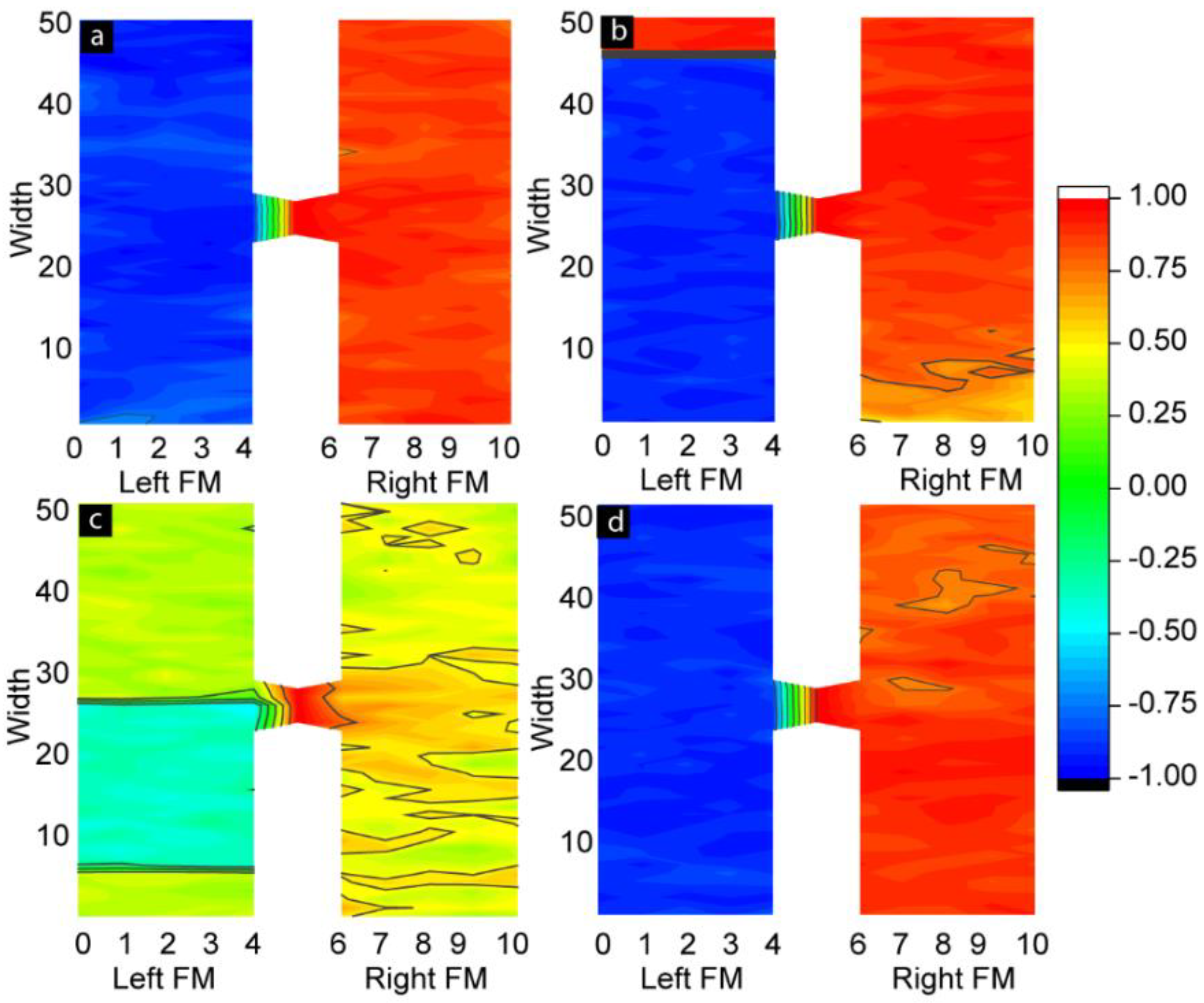
We further investigated the length scale of different phases in ferromagnetic electrodes and the spatial correlation between molecular spins and FM electrodes (
Figure 5). To quantify the correlation of spins between molecules and atoms in different layers of the ferromagnetic electrodes in the presence of in-plane and out-of-plane anisotropies, we studied the customized spatial correlation (
SC) factor. The
SC is the dot product between the average molecular spin vector and the spin vectors in each atomic row of two ferromagnetic electrodes. The equation used to calculate the
SC is as follows (Equation (1)):
A positive
SC represents parallel alignment of the spins of ferromagnetic atoms with the spins of molecules. A negative
SC represents antiparallel alignment of the magnetic moment of atoms of the left and right ferromagnetic electrodes with molecular spins. The magnitude of the
SC suggests the strength of the correlation between the molecule and FM electrode layers. The
SC contours shown in
Figure 5 correspond to the cases of anisotropy shown in the 3D lattice plots in
Figure 3. Here,
Figure 5a is for
ALx = ALy = 0,
Figure 5b for
ALx = 1 and
ALy = 0,
Figure 5c for
ALx = 0 and
ALy = 1, and
Figure 5d for
ALx and
ALy = 1. When
ALx = 0 and
ALy = 0, the spin states of two ferromagnetic electrodes are highly correlated with the spin states of the molecules. Molecule-induced strong antiferromagnetic coupling forced the left and right FM electrodes to assume antiparallel states (
Figure 5a and
Figure 2c). The atomic spins of the left ferromagnetic atoms were negatively correlated with the molecular spins, while the atomic spins of right ferromagnetic electrodes were positively correlated with the molecular spins. These correlations were expected in the MTJMSD Heisenberg model, since molecules were antiferromagnetically and ferromagnetically coupled with the left and right FM electrodes, respectively. In the absence of anisotropies, the antiferromagnetic coupling of molecules with electrodes was dictated by the
JmL = −1 and
JmR = 1 values. It is noteworthy that the segments of the molecules adjacent to the ferromagnetic electrodes tended to align their spins in strong correlation with the spins of the ferromagnetic electrodes, as shown in
Figure 5a,b,d. When the molecular conducting channels were directly on the magnetic phase transition region, multiple magnetic spins were also appeared on the molecular spin states, as shown in
Figure 3b and
Figure 5c. The domain wall width of multiple magnetic phases also depends upon the anisotropy, which is reported elsewhere. In-plane anisotropy causes the formation of multiple magnetic phases of opposite magnetic spins. However, the high value of
ALy caused the formation of a dominant magnetic domain on the left ferromagnetic electrode, represented by the red domain color in
Figure 5b. The magnetic spins of this dominant region are negatively correlated with the molecular spins, and the region stood up to the 47th atomic layer of the left ferromagnetic electrode. The spatial correlation factor is ~−0.8, as shown in
Figure 5b.
A second magnetic domain stands on the 48th, 49th, and 50th atomic layers on the same left ferromagnetic electrode. This domain not only has opposite magnetic spins compared to the dominant magnetic region but is also positively correlated with the molecular magnetic spins, with an equal magnitude of the autocorrelation factor but with the opposite sign, i.e., ~0.8. As discussed previously, out-of-plane anisotropy caused the multiple magnetic phases on the left ferromagnetic electrode (
Figure 5c). From atomic layers 0 to 8, the magnetic spins are positively correlated with the molecular spin, with a correlation factor of ~0.3. From layers 8 to 26, the magnetic spins are negatively correlated with the spin of the molecules, with a correlation factor around −0.35. From layers 27 to 50, the magnetic spins are again positively correlated with the molecular spins, with a correlation factor of ~0.3. It is worth mentioning not only that anisotropy creates different magnetic phases of opposite spins, but also that these phases have spins correlated with molecular spins of equal magnitude but with opposite spin orientations. The right ferromagnetic electrode for this case stabilized in a completely random direction (
Figure 5c). This is due to the anisotropy effect being unable transfer from the left to the right ferromagnetic electrode via the molecular conducting channel. This is because the molecular conducting channels fall in the region of phase transition. As a result, molecular spins are positively correlated with the spins of an electrode and negatively correlated with another electrode. In the present case, when both anisotropies existed, molecular spins were positively correlated with the magnetic spins of the right ferromagnetic electrode, while they were negatively correlated with the magnetic spins of the left electrode (
Figure 5d). The left electrode exhibited a single phase, unlike the appearance of multiple phases observed for unequal in-plane and out-of-plane anisotropies.

 and
and 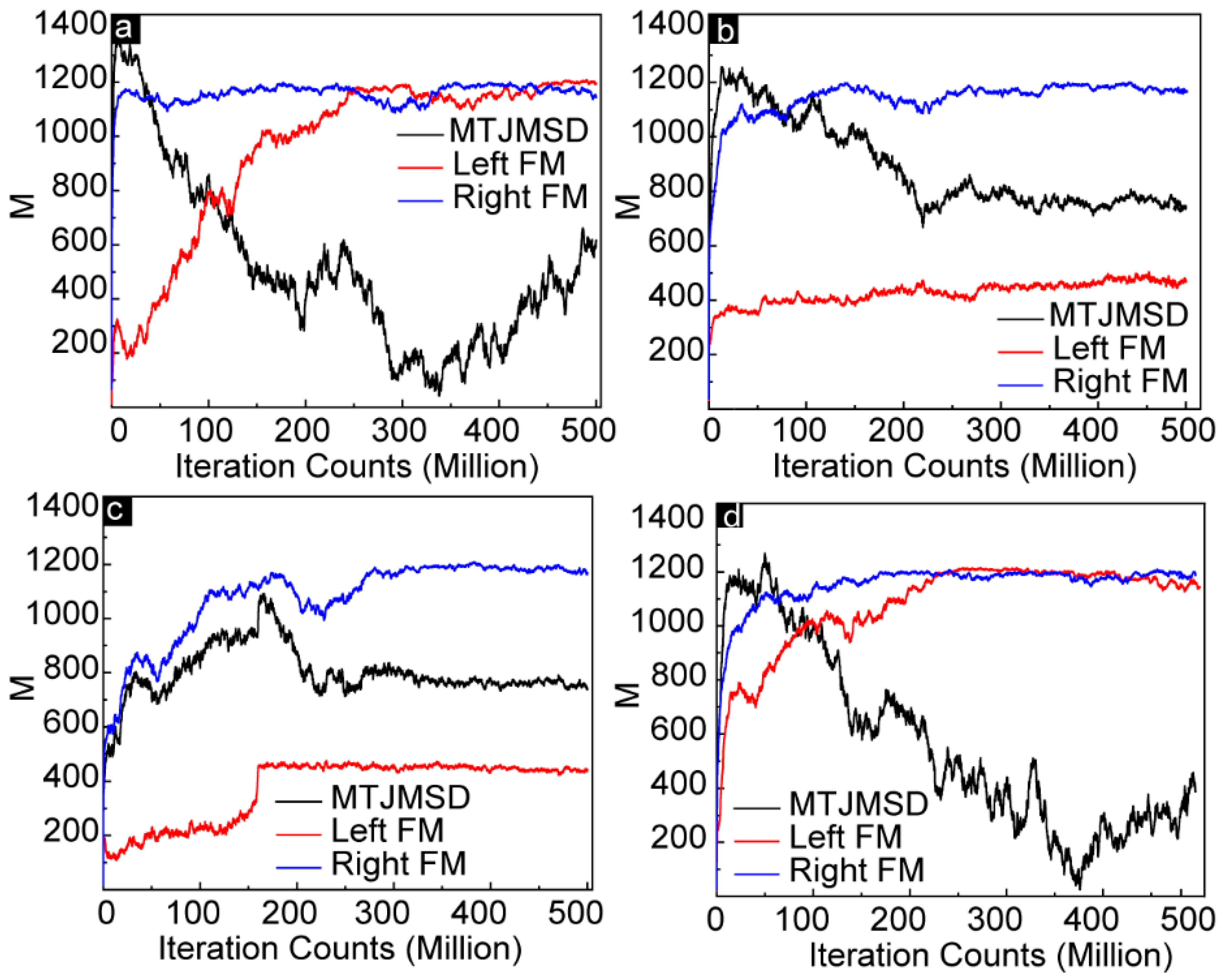


