
Molecular Dynamics Simulation of Coiled Carbon Nanotube Pull-Out from Matrix

Abstract
:1. Introduction
2. Results and Discussion
2.1. Effect of Inner Diameters of the CCNT
2.2. Effect of the Helix Angle
2.3. Effect of the Tube Diameter
3. Methods and Materials
3.1. Modeling the CCNT/PE Interface
3.2. MD Simulation Procedures
4. Conclusions
Author Contributions
Funding
Institutional Review Board Statement
Informed Consent Statement
Data Availability Statement
Conflicts of Interest
References
- Coleman, J.N.; Khan, U.; Blau, W.J.; Gun’ko, Y.K. Small but strong: A review of the mechanical properties of carbon nanotube–polymer composites. Carbon 2006, 44, 1624–1652. [Google Scholar] [CrossRef]
- Liu, L.; Liu, F.; Zhao, J. Curved carbon nanotubes: From unique geometries to novel properties and peculiar applications. Nano Res. 2014, 7, 626–657. [Google Scholar] [CrossRef]
- Ansari, R.; Rouhi, S.; Eghbalian, M. On the elastic properties of curved carbon nanotubes/polymer nanocomposites: A modified rule of mixture. J. Reinf. Plast. Comp. 2017, 36, 991–1008. [Google Scholar] [CrossRef]
- Xie, J.; Mukhopadyay, K.; Yadev, J.; Varadan, V.K. Catalytic chemical vapor deposition synthesis and electron microscopy observation of coiled carbon nanotubes. Smart. Mater. Struct. 2003, 12, 744–748. [Google Scholar] [CrossRef]
- Chen, X.; Zhang, S.; Dikin, D.A.; Ding, W.; Ruoff, R.S.; Pan, L.; Nakayama, Y. Mechanics of a carbon nanocoil. Nano Lett. 2003, 3, 1299–1304. [Google Scholar] [CrossRef]
- Ma, H.L.; Jia, Z.; Lau, K.T.; Li, X.; Hui, D.; Shi, S.Q. Enhancement on mechanical strength of adhesively-bonded composite lap joints at cryogenic environment using coiled carbon nanotubes. Comp. Part B Eng. 2017, 110, 396–401. [Google Scholar] [CrossRef]
- Liu, X.; Yang, Q.S.; Liew, K.M.; He, X.Q. Superstretchability and stability of helical structures of carbon nanotube/polymer composite fibers: Coarse-grained molecular dynamics modeling and simulation. Carbon 2017, 115, 220–228. [Google Scholar] [CrossRef]
- Fakhrabadi, M.M.S.; Amini, A.; Reshadi, F.; Khani, N.; Rastgoo, A. Investigation of buckling and vibration properties of hetero-junctioned and coiled carbon nanotubes. Comp. Mater. Sci. 2013, 73, 93–112. [Google Scholar] [CrossRef]
- Ju, S.P.; Lin, J.S.; Chen, H.L.; Hsieh, J.Y.; Chen, H.T.; Weng, M.H.; Zhao, J.J.; Liu, L.Z.; Chen, M.C. A molecular dynamics study of the mechanical properties of a double-walled carbon nanocoil. Comp. Mater. Sci. 2014, 82, 92–99. [Google Scholar] [CrossRef]
- Feng, C.; Liew, K.M.; He, P.; Wu, A. Predicting mechanical properties of carbon nanosprings based on molecular mechanics simulation. Compos. Struct. 2014, 114, 41–50. [Google Scholar] [CrossRef]
- Ghaderi, S.H.; Hajiesmaili, E. Molecular structural mechanics applied to coiled carbon nanotubes. Comp. Mater. Sci. 2012, 55, 344–349. [Google Scholar] [CrossRef]
- Ghaderi, S.H.; Hajiesmaili, E. Nonlinear analysis of coiled carbon nanotubes using the molecular dynamics finite element method. Mater. Sci. Eng. A 2013, 582, 225–234. [Google Scholar] [CrossRef]
- Wu, J.; Nagao, S.; He, J.; Zhang, Z. Nanohinge-induced plasticity of helical carbon nanotubes. Small 2013, 9, 3561–3566. [Google Scholar] [CrossRef] [PubMed]
- Tian, L.; Guo, X. Fracture and defect evolution in carbon nanocoil-A molecular dynamics study. Comp. Mater. Sci. 2015, 103, 126–133. [Google Scholar] [CrossRef]
- Zaeri, M.M.; Ziaei-Rad, S. Elastic behavior of carbon nanocoils: A molecular dynamics study. AIP Adv. 2015, 5, 117114. [Google Scholar] [CrossRef]
- Wernik, J.M.; Cornwell-Mott, B.J.; Meguid, S.A. Determination of the interfacial properties of carbon nanotube reinforced polymer composites using atomistic-based continuum model. Int. J. Solids Struct. 2012, 49, 1852–1863. [Google Scholar] [CrossRef]
- Jiang, C.; Saha, A.; Martí, A.A. Carbon nanotubides: An alternative for dispersion, functionalization and composites fabrication. Nanoscale 2015, 7, 15037–15045. [Google Scholar] [CrossRef]
- Gkikas, G.; Paipetis, A.S. Optimisation and analysis of the reinforcement effect of carbon nanotubes in a typical matrix system. Meccanica 2015, 50, 461–478. [Google Scholar] [CrossRef]
- Cooper, C.A.; Cohen, S.R.; Barber, A.H.; Wagner, H.D. Detachment of nanotubes from a polymer matrix. Appl. Phys. Lett. 2002, 81, 3873–3875. [Google Scholar] [CrossRef]
- Wagner, H.D.; Lourie, O.; Feldman, Y.; Tenne, R. Stress-induced fragmentation of multiwall carbon nanotubes in a polymer matrix. Appl. Phys. Lett. 1998, 72, 188–190. [Google Scholar] [CrossRef]
- Wang, Z.J.; Kwon, D.J.; Choi, J.Y.; Shin, P.S.; Yi, J.W.; Byun, J.H.; Lee, H.I.; Park, J.K.; DeVries, K.L.; Park, J.M. Inherent and interfacial evaluations of carbon nanotubes/epoxy composites and single carbon fiber at different temperatures. Comp. Part B Eng. 2016, 91, 111–118. [Google Scholar] [CrossRef]
- Zu, M.; Li, Q.; Zhu, Y.; Dey, M.; Wang, G.; Lu, W.; Deitzel, J.M.; Gillespie, J.W.; Byun, J.H.; Chou, T.W. The effective interfacial shear strength of carbon nanotube fibers in an epoxy matrix characterized by a microdroplet test. Carbon 2012, 50, 1271–1279. [Google Scholar] [CrossRef]
- Tsuda, T.; Ogasawara, T.; Deng, F.; Takeda, N. Direct measurements of interfacial shear strength of multi-walled carbon nanotube/PEEK composite using a nano-pullout method. Comp. Sci. Technol. 2011, 71, 1295–1300. [Google Scholar] [CrossRef]
- Chen, X.; Zheng, M.; Park, C.; Ke, C. Direct measurements of the mechanical strength of carbon nanotube–poly (methyl methacrylate) interfaces. Small 2013, 9, 3345–3351. [Google Scholar] [CrossRef] [PubMed]
- Yazdchi, K.; Salehi, M. The effects of CNT waviness on interfacial stress transfer characteristics of CNT/polymer composites. Compos. Part A Appl. Sci. Manuf. 2011, 42, 1301–1309. [Google Scholar] [CrossRef]
- Chen, X.; Beyerlein, I.J.; Brinson, L.C. Curved-fiber pull-out model for nanocomposites. Part 1: Bonded stage formulation. Mech. Mater. 2009, 41, 279–292. [Google Scholar] [CrossRef]
- Chen, X.; Beyerlein, I.J.; Brinson, L.C. Curved-fiber pull-out model for nanocomposites. Part 2: Interfacial debonding and sliding. Mech. Mater. 2009, 41, 293–307. [Google Scholar] [CrossRef]
- Chen, X.; Beyerlein, I.J.; Brinson, L.C. Bridged crack models for the toughness of composites reinforced with curved nanotubes. J. Mech. Phys. Solids 2011, 59, 1938–1952. [Google Scholar] [CrossRef]
- Wang, L.; Cui, Y.; Qin, Q.; Wang, H.; Wang, J. Helical fiber pull-out in biological materials. Acta. Mech. Solida. Sin. 2016, 29, 245–256. [Google Scholar] [CrossRef]
- Ma, H.L.; Lau, K.T.; Hui, D.; Shi, S.Q.; Poon, C.K. Theoretical analysis on the pullout behavior of carbon nanotube at cryogenic environment with the consideration of thermal residual stress. Comp. Part B Eng. 2017, 128, 67–75. [Google Scholar] [CrossRef]
- Gao, X.L.; Li, K. A shear-lag model for carbon nanotube-reinforced polymer composites. Int. J. Solids Struct. 2005, 42, 1649–1667. [Google Scholar] [CrossRef]
- Nam, K.H. Molecular dynamics-from macromolecule to small molecules. Int. J. Mol. Sci. 2022, 23, 5676. [Google Scholar] [CrossRef] [PubMed]
- Li, Y.; Liu, Y.; Peng, X.; Yan, C.; Liu, S.; Hu, N. Pull-out simulations on interfacial properties of carbon nanotube-reinforced polymer nanocomposites. Comp. Mater. Sci. 2011, 50, 1854–1860. [Google Scholar] [CrossRef]
- Wu, W.Q.; He, C.S.; Qiang, Y.B.; Peng, H.J.; Zhou, M.Y. Polymer-metal interfacial friction characteristics under ultrasonic plasticizing conditions: A united-atom molecular dynamics study. Int. J. Mol. Sci. 2022, 23, 2829. [Google Scholar] [CrossRef]
- Shin, D.; Jeon, I.; Yang, S. Multiscale modeling assessment of the interfacial properties and critical aspect ratio of structurally defected graphene in polymer nanocomposites for defect engineering. Eur. J. Mech. A-Solid 2022, 96, 104728. [Google Scholar] [CrossRef]
- Sahraei, A.; Mokarizadeh, A.; Foroutan, M.; George, D.; Rodrigue, D.; Baniassadi, M. Atomistic simulation of interfacial properties and damage mechanism in graphene nanoplatelet/epoxy composites. Comp. Mater. Sci. 2020, 184, 109888. [Google Scholar] [CrossRef]
- Cui, J.; Zhao, J.; Wang, S.; Li, Y. A comparative study on enhancement of mechanical and tribological properties of nitrile rubber composites reinforced by different functionalized graphene sheets: Molecular dynamics simulations. Polym. Compos. 2021, 42, 205–219. [Google Scholar] [CrossRef]
- Gaikwad, P.; Kowalik, M.; Jensen, B.; van Duin, A.; Odegard, G. Molecular dynamics modeling of interfacial interactions between flattened carbon nanotubes and amorphous carbon: Implications for ultra-lightweight composites. ACS Appl. Nano Mater. 2022, 5, 5915–5924. [Google Scholar] [CrossRef]
- Song, Z.; Li, Y.; Yang, B. The interfacial load-transfer enhancement mechanism of amino-functionalised carbon nanotube reinforced epoxy matrix composites: A molecular dynamics study. Compos. Sci. Technol. 2021, 209, 108790. [Google Scholar] [CrossRef]
- Cui, W.; Huang, W.; Hassan, H.; Cai, X.; Wu, K. Study on the interfacial contact behavior of carbon nanotubes and asphalt binders and adhesion energy of modified asphalt on aggregate surface by using molecular dynamics simulation. Constr. Build. Mater. 2022, 316, 125849. [Google Scholar] [CrossRef]
- Kayang, K.; Banna, A.; Volkov, A. Chirality-dependent mechanical properties of bundles and thin films composed of covalently cross-linked carbon nanotubes. Langmuir 2022, 38, 1977–1994. [Google Scholar] [CrossRef] [PubMed]
- Lyu, H.; Jiang, N.; Li, Y.; Lee, H.; Zhang, D. Enhanced interfacial and mechanical properties of carbon fiber/PEEK composites by hydroxylated PEEK and carbon nanotubes. Compos. Part A Appl. S. 2021, 145, 106364. [Google Scholar] [CrossRef]
- Li, C.; Zhang, Z.; Zhan, H.; Zheng, Z.; Bai, J.; Gu, Y. Mechanical properties of single-layer diamond reinforced poly(vinyl alcohol) nanocomposites through atomistic simulation. Macromol. Mater. Eng. 2021, 306, 2100292. [Google Scholar] [CrossRef]
- Alian, A.R.; Kundalwal, S.I.; Meguid, S.A. Interfacial and mechanical properties of epoxy nanocomposites using different multiscale modeling schemes. Compos. Struct. 2015, 131, 545–555. [Google Scholar] [CrossRef]
- Alian, A.R.; Meguid, S.A. Molecular dynamics simulations of the effect of waviness and agglomeration of CNTs on interface strength of thermoset nanocomposites. Phys. Chem. Chem. Phys. 2017, 19, 4426–4434. [Google Scholar] [CrossRef]
- Vu-Bac, N.; Lahmer, T.; Zhang, Y.; Zhuang, X.; Rabczuk, T. Stochastic predictions of interfacial characteristic of polymeric nanocomposites (PNCs). Comp. Part B Eng. 2014, 59, 80–95. [Google Scholar] [CrossRef]
- Sertchook, H.; Elimelech, H.; Makarov, C.; Khalfin, R.; Cohen, Y.; Shuster, M.; Babonneau, F.; Avnir, D. Composite particles of polyethylene@ silica. J. Am. Chem. Soc. 2017, 129, 98–108. [Google Scholar] [CrossRef]
- Kanagaraj, S.; Varanda, F.R.; Zhil’tsova, T.V.; Oliveira, M.S.; Simões, J.A. Mechanical properties of high density polyethylene/carbon nanotube composites. Compos. Sci. Technol. 2007, 67, 3071–3077. [Google Scholar] [CrossRef]
- McNally, T.; Pötschke, P.; Halley, P.; Murphy, M.; Martin, D.; Bell, S.E.; Brennan, G.P.; Bein, D.; Lemoine, P.; Quinn, J.P. Polyethylene multiwalled carbon nanotube composites. Polymer 2015, 46, 8222–8232. [Google Scholar] [CrossRef]
- Gou, J.; Liang, Z.; Zhang, C.; Wang, B. Computational analysis of effect of single-walled carbon nanotube rope on molecular interaction and load transfer of nanocomposites. Compos. Part B Eng. 2005, 36, 524–533. [Google Scholar] [CrossRef]
- Yang, H.; Chen, Y.; Liu, Y.; Cai, W.S.; Li, Z.S. Molecular dynamics simulation of polyethylene on single wall carbon nanotube. J. Chem. Phys. 2007, 127, 094902. [Google Scholar] [CrossRef] [PubMed]
- Plimpton, S. Fast parallel algorithms for short-range molecular dynamics. J. Comp. Phys. 1995, 117, 1–19. [Google Scholar] [CrossRef]
- Brenner, D.W.; Shenderova1, O.A.; Harrison, J.A.; Stuart, S.J.; Ni, B.; Sinnott, S.B. A second-generation reactive empirical bond order (REBO) potential energy expression for hydrocarbons. J. Phys.-Condens. Mat. 2002, 14, 783–802. [Google Scholar] [CrossRef]
- Zhang, Y.; Zhao, J.; Wei, N.; Jiang, J.; Gong, Y.; Rabczuk, T. Effects of the dispersion of polymer wrapped two neighbouring single walled carbon nanotubes (SWNTs) on nanoengineering load transfer. Comp. Part B Eng. 2013, 45, 1714–1721. [Google Scholar] [CrossRef]
- Zhang, Y.; Zhuang, X.; Muthu, J.; Mabrouki, T.; Fontaine, M.; Gong, Y.; Rabczuk, T. Load transfer of graphene/carbon nanotube/polyethylene hybrid nanocomposite by molecular dynamics simulation. Comp. Part B Eng. 2014, 63, 27–33. [Google Scholar] [CrossRef]
- Lu, Y.B.; Yang, Q.S.; He, X.Q.; Liew, K.M. Modeling the interfacial behavior of carbon nanotube fiber/polyethylene composites by molecular dynamics approach. Comp. Mater. Sci. 2016, 114, 189–198. [Google Scholar] [CrossRef]
- Vu-Bac, N.; Lahmer, T.; Keitel, H.; Zhao, J.; Zhuang, X.; Rabczuk, T. Stochastic predictions of bulk properties of amorphous polyethylene based on molecular dynamics simulations. Mech. Mater. 2014, 68, 70–84. [Google Scholar] [CrossRef]
- Capaldi, F.M.; Boyce, M.C.; Rutledge, G.C. Molecular response of a glassy polymer to active deformation. Polymer 2004, 45, 1391–1399. [Google Scholar] [CrossRef]
- Zhang, X.F.; Zhang, Z. Polygonal spiral of coil-shaped carbon nanotubules. Phys. Rev. B 1995, 52, 5313–5317. [Google Scholar] [CrossRef]
- Amelinckx, S.; Zhang, X.B.; Bernaerts, D.; Zhang, X.F.; Ivanov, V.; Nagy, J.B. A formation mechanism for catalytically grown helix-shaped graphite nanotubes. Science 1994, 265, 635–639. [Google Scholar] [CrossRef]
- Bajpai, V.; Dai, L.; Ohashi, T. Large-scale synthesis of perpendicularly aligned helical carbon nanotubes. J. Am. Chem. Soc. 2014, 126, 5070–5071. [Google Scholar] [CrossRef] [PubMed]
- Liu, L.Z.; Gao, H.L.; Zhao, J.J.; Lu, J.P. Superelasticity of carbon nanocoils from atomistic quantum simulations. Nanoscale Res. Lett. 2010, 5, 478–483. [Google Scholar] [CrossRef] [PubMed]
- Isralewitz, B.; Gao, M.; Schulten, K. Steered molecular dynamics and mechanical functions of proteins. Curr. Opin. Struc. Biol. 2001, 11, 224–230. [Google Scholar] [CrossRef]
- Büyüköztürk, O.; Buehler, M.J.; Lau, D.; Tuakta, C. Structural solution using molecular dynamics: Fundamentals and a case study of epoxy-silica interface. Int. J. Solids Struct. 2011, 48, 2131–2140. [Google Scholar] [CrossRef]
- Saha, L.C.; Mian, S.A.; Jang, J.K. Molecular dynamics simulation study on the carbon nanotube interacting with a polymer. B. Korean. Chem. Soc. 2012, 33, 893–896. [Google Scholar] [CrossRef]
- Darvishi, F.; Rahmani, O. Calibration of nonlocal generalized helical beam model for free vibration analysis of coiled carbon nanotubes via molecular dynamics simulations. Mech. Adv. Mater. Struc. 2022, 1, 247282721. [Google Scholar] [CrossRef]
- Yi, P.; Locker, C.R.; Rutledge, G.C. Molecular dynamics simulation of homogeneous crystal nucleation in polyethylene. Macromolecules 2013, 46, 4723–4733. [Google Scholar] [CrossRef]
- Awasthi, A.P.; Lagoudas, D.C.; Hammerand, D.C. Modeling of graphene–polymer interfacial mechanical behavior using molecular dynamics. Mater. Sci. Eng. 2018, 17, 015002. [Google Scholar] [CrossRef]
- Han, J.; Gee, R.H.; Boyd, R.H. Glass transition temperatures of polymers from molecular dynamics simulations. Macromolecules 1994, 27, 7781–7784. [Google Scholar] [CrossRef]
- Martínez, J.; Martínez, L. Packing optimization for automated generation of complex system's initial configurations for molecular dynamics and docking. J. Comput. Chem. 2003, 24, 819–825. [Google Scholar] [CrossRef]
- Haghighatpanah, S.; Bohlén, M.; Bolton, K. Molecular level computational studies of polyethylene and polyacrylonitrile composites containing single walled carbon nanotubes: Effect of carboxylic acid functionalization on nanotube-polymer interfacial properties. Front. Chem. 2014, 2, 74. [Google Scholar] [CrossRef] [PubMed]
- Yang, L.; Tong, L.; He, X. MD simulation of carbon nanotube pullout behavior and its use in determining mode I delamination toughness. Comp. Mater. Sci. 2012, 55, 356–364. [Google Scholar] [CrossRef]
- Chawla, R.; Sharma, S. Molecular dynamics simulation of carbon nanotube pull-out from polyethylene matrix. Compos. Sci. Technol. 2017, 144, 169–177. [Google Scholar] [CrossRef]
- Vallittu, P. High-aspect ratio fillers: Fiber-reinforced composites and their anisotropic properties. Dent. Mater. 2015, 1, 1–7. [Google Scholar] [CrossRef] [PubMed]
- Marcuello, C.; Foulon, L.; Chabbert, B.; Molinari, M.; Aguie-Beghin, V. Langmuir-blodgett procedure to precisely control the coverage of functionalized AFM cantilevers for SMFS measurements: Application with cellulose nanocrystals. Langmuir 2018, 34, 9376–9386. [Google Scholar] [CrossRef]
- Mena-Álvarez, J.; Agustin-Panadero, R.; Zubizarreta-Macho, A. Effect of fiber-reinforced composite and elastic post on the fracture resistance of premolars with root canal treatment-an in vitro pilot study. Appl. Sci. 2020, 10, 7616. [Google Scholar] [CrossRef]
- Berzin, F.; Lemkhanter, L.; Marcuello, C.; Chabbert, B.; Aguie-Beghin, V.; Molinari, M.; Castellani, R.; Vergnes, B. Influence of the polarity of the matrix on the breakage mechanisms of lignocellulosic fibers during twin-screw extrusion. Polym. Compos. 2020, 41, 1106–1117. [Google Scholar] [CrossRef]


| Case # | Type | Outer Diameter (Dt) (Å) | Helix Angle (α) (°) | Tube Diameter (dc) (Å) | Inner Diameter (Dc) (Å) | Maximal Pullout Force (nN) | ISS (MPa) |
|---|---|---|---|---|---|---|---|
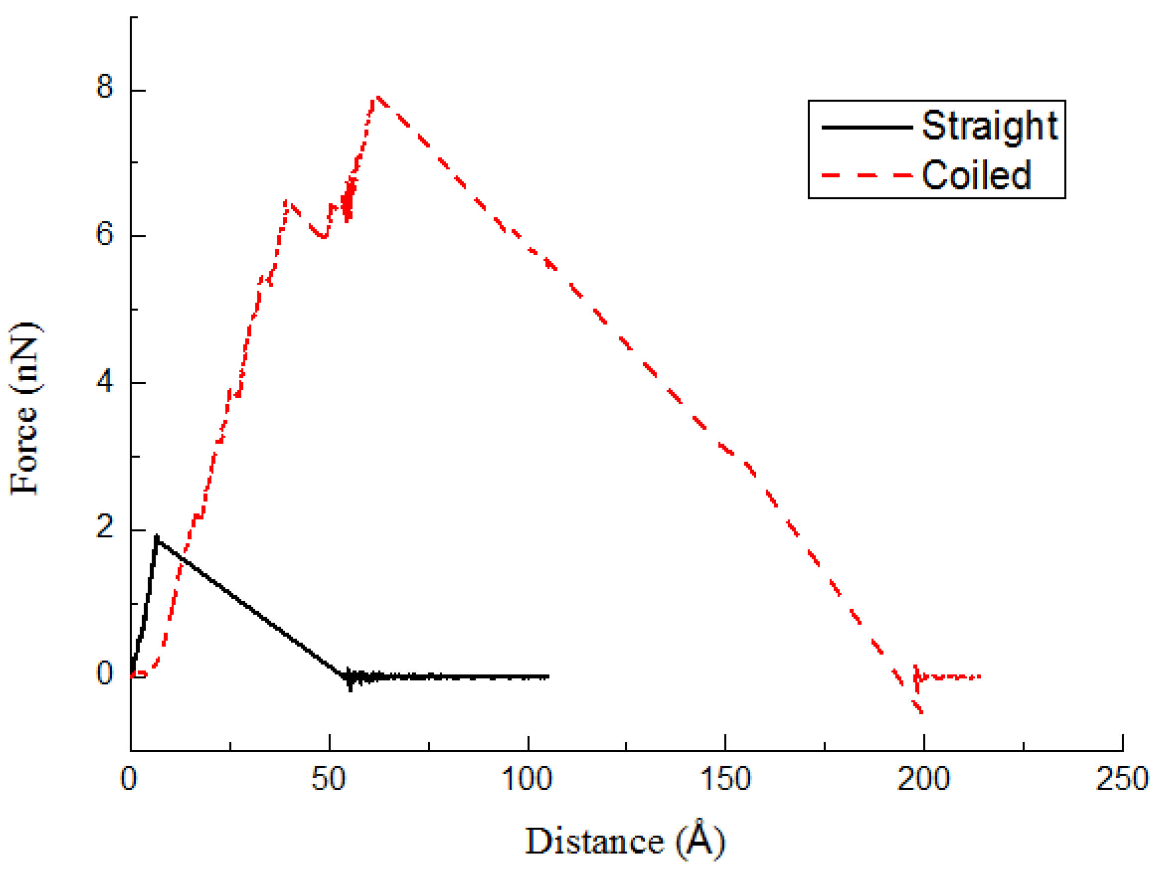
| 2 | CNT | 11.3 | - | 11.3 | - | 1.946 | 127 |
| 3 | CCNT | 37.4 | 14.4 | 11.3 | 14.8 | 7.917 | 149 |
| Case # | Outer Diameter (Dt) (Å) | Helix Angle (α) (°) | Tube Diameter (dc) (Å) | Inner Diameter (Dc) (Å) | Maximal Pullout Force (nN) | ISS (MPa) |
|---|---|---|---|---|---|---|
| 4 | 32.6 | 16 | 11.3 | 10 | 7.35 | 155 |
| 5 | 36.6 | 16 | 11.3 | 14 | 6.61 | 142.1 |
| 6 | 37.4 | 16 | 11.3 | 14.8 | 6.167 | 132.5 |
| Case # | Outer Diameter (Dt) (Å) | Helix Angle (α) (°) | Tube Diameter (dc) (Å) | Inner Diameter (Dc) (Å) | Maximal Pullout Force (nN) | ISS (MPa) |
|---|---|---|---|---|---|---|
| 6 | 37.4 | 16 | 11.3 | 14.8 | 6.167 | 132.5 |
| 7 | 37.4 | 14.4 | 11.3 | 14.8 | 7.917 | 149 |
| 8 | 37.4 | 13.9 | 11.3 | 14.8 | 8.631 | 153.8 |
| Case # | Outer Diameter (Dt) (Å) | Helix Angle (α) (°) | Tube Diameter (dc) (Å) | Inner Diameter (Dc) (Å) | Maximal Pullout Force (nN) | ISS (MPa) |
|---|---|---|---|---|---|---|
| 9 | 29.4 | 14 | 7.6 | 14.2 | 3.12 | 168 |
| 10 | 30 | 14 | 8.2 | 13.6 | 3.32 | 163 |
| 11 | 29.5 | 14 | 9.5 | 10.5 | 4.45 | 160 |
| Interaction | Form | Parameters |
|---|---|---|
| Bond | kJ/mol Å, leq = 1.53 Å | |
| Angle | = = 110° | |
| Torsional | k0 = 14.477, k1 = 37.594, k2 = 6.493, k3 = 58.499 (kJ/mol) | |
| Non-bonded | ε = 0.468 kJ/mol,
= 4.01 Å, rc = 10.0 Å |
| Case # | Type | Outer Diameter (Dt) (Å) | Helix Angle (α) (°) | Tube Diameter (dc) (Å) | Inner Diameter (Dc) (Å) |
|---|---|---|---|---|---|
| 1 | CNT | 8.14 | - | 8.14 | - |
| 2 | CNT | 11.3 | - | 11.3 | - |
| 3 | CCNT | 37.4 | 14.4 | 11.3 | 14.8 |
| 4 | CCNT | 32.6 | 16 | 11.3 | 10 |
| 5 | CCNT | 36.6 | 16 | 11.3 | 14 |
| 6 | CCNT | 37.4 | 16 | 11.3 | 14.8 |
| 7 | CCNT | 37.4 | 14.4 | 11.3 | 14.8 |
| 8 | CCNT | 37.4 | 13.9 | 11.3 | 14.8 |
| 9 | CCNT | 29.4 | 14 | 7.6 | 14.2 |
| 10 | CCNT | 30 | 14 | 8.2 | 13.6 |
| 11 | CCNT | 29.5 | 14 | 9.5 | 10.5 |
Publisher’s Note: MDPI stays neutral with regard to jurisdictional claims in published maps and institutional affiliations. |
© 2022 by the authors. Licensee MDPI, Basel, Switzerland. This article is an open access article distributed under the terms and conditions of the Creative Commons Attribution (CC BY) license (https://creativecommons.org/licenses/by/4.0/).
Share and Cite
Huang, F.; Zhou, S. Molecular Dynamics Simulation of Coiled Carbon Nanotube Pull-Out from Matrix. Int. J. Mol. Sci. 2022, 23, 9254. https://doi.org/10.3390/ijms23169254
Huang F, Zhou S. Molecular Dynamics Simulation of Coiled Carbon Nanotube Pull-Out from Matrix. International Journal of Molecular Sciences. 2022; 23(16):9254. https://doi.org/10.3390/ijms23169254
Chicago/Turabian StyleHuang, Feng, and Shuai Zhou. 2022. "Molecular Dynamics Simulation of Coiled Carbon Nanotube Pull-Out from Matrix" International Journal of Molecular Sciences 23, no. 16: 9254. https://doi.org/10.3390/ijms23169254