
Electrocatalytic Degradation of Phenolic Wastewater Using a Zero-Gap Flow-Through Reactor Coupled with a 3D Ti/RuO2-TiO2@Pt Electrode

Abstract
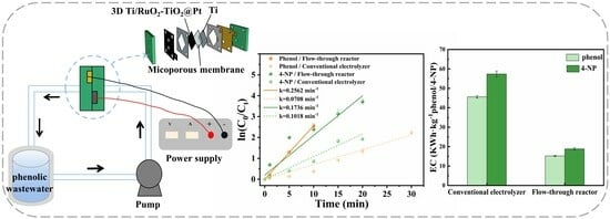
:
1. Introduction
2. Results and Discussion
2.1. Effect of Electrolyte Type and Concentration
2.2. Effect of Current Density
2.3. Effect of Initial Concentration of Phenol and 4-NP
2.4. Effect of Initial pH
2.5. Reactor Comparison
2.6. Degradation Pathways of Phenol and 4-NP
3. Experiment
3.1. Chemical Reagents and Materials
3.2. Preparation of Electrodes
3.3. Zero-Gap Flow-Through Reactor
3.4. Analytical Methods
4. Conclusions
Supplementary Materials
Author Contributions
Funding
Institutional Review Board Statement
Informed Consent Statement
Data Availability Statement
Conflicts of Interest
References
- Saratale, R.G.; Hwang, K.J.; Song, J.; Saratale, G.D.; Kim, D.S. Electrochemical Oxidation of Phenol for Wastewater Treatment Using Ti/PbO2 Electrode. J. Environ. Eng. 2016, 142, 04015064. [Google Scholar] [CrossRef]
- Lee, H.J.; Park, C.; Yeo, I.; Park, J.H.; Magnone, E. Successful removal of phenol from industrial wastewater using novel hydrophobic modified ceramic hollow fiber membrane contactors with remarkably high stability. J. Ind. Eng. Chem. 2022, 114, 402–408. [Google Scholar] [CrossRef]
- Abbas, Z.I.; Abbas, A.S. Oxidative degradation of phenolic wastewater by electro fenton process using MnO2-graphite electrode. J. Environ. Chem. Eng. 2019, 7, 103108. [Google Scholar] [CrossRef]
- Said, K.A.M.; Ismail, A.F.; Karim, Z.A.; Abdullah, M.S.; Hafeez, A. A review of technologies for the phenolic compounds recovery and phenol removal from wastewater. Process Saf. Environ. Prot. 2019, 151, 257–289. [Google Scholar] [CrossRef]
- Hernández, D.F.; Giraldo, L.; Moreno, J.C. Dataset on adsorption of phenol onto activated carbons: Equilibrium, kinetics and mechanism of adsorption. Data Br. 2020, 32, 106312. [Google Scholar] [CrossRef]
- He, C.; Yang, C.; Yuan, S.; Hu, Z.; Wang, W. Effects of sludge retention time on the performance of anaerobic ceramic membrane bioreactor treating high-strength phenol wastewater. Archaea 2020, 2020, 8895321. [Google Scholar] [CrossRef]
- Lima, V.N.; Rodrigues, C.S.D.; Brandão, Y.B.; Benachour, M.; Madeira, L.M. Optimisation of the degradation of 4-nitrophenol by Fenton’s process. J. Water Process Eng. 2022, 47, 102685. [Google Scholar] [CrossRef]
- Saputera, W.H.; Putrie, A.S.; Esmailpour, A.A.; Sasongko, D.; Suendo, V.; Mukti, R.R. Technology Advances in Phenol Removals: Current Progress and Future Perspectives. Catalysts 2021, 11, 998. [Google Scholar] [CrossRef]
- Xu, M.; Wang, J.; Liang, X.; Fang, W.; Zhu, C.; Wang, F. MOF-derived ZrO2-C nanoparticles modified PbO2 electrode for high-efficiency electrocatalytic degradation of nitrophenolic compounds in wastewater. Sep. Purif. Technol. 2023, 318, 123921. [Google Scholar] [CrossRef]
- Hou, K.; Zhu, G.; Liu, Y.; Quan, X. Enhanced electrochemical oxidation of perfluorooctanoic acid on Ti/SnO2-Sb electrode by surface morphology regulation. Chin. Chem. Lett. 2023, 35, 108704. [Google Scholar] [CrossRef]
- Tang, S.; Luo, Z.; Liao, J.; Liu, Z.; Niu, J. Degradation and detoxification mechanisms of organophosphorus flame retardant tris (1,3-dichloro-2-propyl) phosphate (TDCPP) during electrochemical oxidation process. Chin. Chem. Lett. 2023, 34, 108090. [Google Scholar] [CrossRef]
- Li, M.; Feng, C.; Hu, W.; Zhang, Z.; Norio, S. Electrochemical degradation of phenol using electrodes of Ti/RuO2-Pt and Ti/IrO2-Pt. J. Hazard. Mater. 2009, 162, 455–462. [Google Scholar] [CrossRef]
- Barışçı, S.; Turkay, O.; Öztürk, H.; Şeker, M.G. Anodic Oxidation of Phenol by Mixed-Metal Oxide Electrodes: Identification of Transformation By-Products and Toxicity Assessment. J. Electrochem. Soc. 2017, 164, 129–137. [Google Scholar] [CrossRef]
- Can, O.T.; Tutun, M.M.; Keyikoglu, R. Anodic oxidation of bisphenol A by different dimensionally stable electrodes. Water Sci. Technol. 2021, 83, 1907–1919. [Google Scholar] [CrossRef] [PubMed]
- Yu, N.; Cao, H.; Hong, X.; Mao, X.; Li, T.; Yuan, H.; Li, J.; Luo, F.; Li, M. Comparison of Ti/PbO2 electrode and Ti/RuO2-IrO2 electrode on their electrochemical performance. J. Solid State Electrochem. 2023, 05730. [Google Scholar] [CrossRef]
- Zhou, J.; Wang, T.; Cheng, C.; Pan, F.; Zhu, Y.; Ma, H.; Niu, J. Ultralong-lifetime Ti/RuO2-IrO2@Pt anodes with a strong metal-support interaction for efficient electrochemical mineralization of perfluorooctanoic acid. Nanoscale 2022, 14, 3579–3588. [Google Scholar] [CrossRef] [PubMed]
- Zhu, Y.; Li, B.; Wang, Y.; Wang, T. Preparation of porous Ti/RuO2-IrO2@Pt, Ti/RuO2-TiO2@Pt and Ti/Y2O3-RuO2-TiO2@Pt anodes for efficient electrocatalytic decomposition of tetracycline. Molecules 2023, 28, 2189. [Google Scholar] [CrossRef] [PubMed]
- Yang, C.; Fan, Y.; Li, P.; Gu, Q.; Li, X. Freestanding 3-dimensional macro-porous SnO2 electrodes for efficient electrochemical degradation of antibiotics in wastewater. Chem. Eng. J. 2021, 422, 130032. [Google Scholar] [CrossRef]
- Mousset, E.; Dionysiou, D. Photoelectrochemical reactors for treatment of water and wastewater: A review. Environ. Chem. Lett. 2020, 18, 1301–1318. [Google Scholar] [CrossRef]
- Alrehaili, O.; Fajardo, A.; Segura, S.; Westerhoff, P. Microfluidic flow-by reactors minimize energy requirements of electrochemical water treatment without adding supporting electrolytes. Sep. Purif. Technol. 2023, 310, 123123. [Google Scholar] [CrossRef]
- Gonzaga, I.M.D.; Dória, A.R.; Moratalla, A.; Eguiluz, K.I.B.; Salazar, G.R.; Cañizares, P.; Rodrigo, M.A.; Saez, C. Electrochemical systems equipped with 2D and 3D microwave-made anodes for the highly efficient degradation of antibiotics in urine. Electrochim. Acta 2021, 392, 139012. [Google Scholar] [CrossRef]
- Santos, G.O.S.; Gonzaga, I.M.D.; Dória, A.R.; Moratalla, A.; Silva, R.S.; Eguiluz, K.B.; Salazar, G.R.; Saez, C.; Rodrigo, M.A. Testing and scaling-up of a novel Ti/Ru0.7Ti0.3O2 mesh anode in a microfluidic flow-through reactor. Chem. Eng. J. 2020, 398, 125568. [Google Scholar] [CrossRef]
- Zhou, C.; Wang, Y.; Chen, J.; Niu, J. Electrochemical degradation of sunscreen agent benzophenone-3 and its metabolite by Ti/SnO2-Sb/Ce-PbO2 anode: Kinetics, mechanism, toxicity and energy consumption. Sci. Total Environ. 2019, 688, 75–82. [Google Scholar] [CrossRef]
- Luu, L.; Ngan, P.T.K. Fabrication of high performance Ti/SnO2-Nb2O5 electrodes for electrochemical textile wastewater treatment. Sci. Total Environ. 2022, 860, 160366. [Google Scholar] [CrossRef]
- Fernandes, A.; Santos, D.; Pacheco, M.J.; Ciríaco, L.; Lopes, A. Electrochemical oxidation of humic acid and sanitary landfill leachate: Influence of anode material, chloride concentration and current density. Sci. Total Environ. 2016, 541, 282–291. [Google Scholar] [CrossRef]
- Ansari, A.; Nematollahi, D. Convergent paired electrocatalytic degradation of p-dinitrobenzene by Ti/SnO2-Sb/β-PbO2 anode. A new insight into the electrochemical degradation mechanism. Appl. Catal. B Environ. 2020, 261, 118226. [Google Scholar] [CrossRef]
- Souri, Z.; Ansari, A.; Nematollahi, D.; Ardakani, M. Electrocatalytic degradation of dibenzoazepine drugs by fluorine doped β-PbO2 electrode: New insight into the electrochemical oxidation and mineralization mechanisms. Electroanal. Chem. 2020, 862, 114037. [Google Scholar] [CrossRef]
- Wang, C.; Yu, Y.; Yin, L.; Niu, J.; Hou, L. Insights of ibuprofen electro-oxidation on metal-oxide-coated Ti anodes: Kinetics, energy consumption and reaction mechanisms. Chemosphere 2016, 163, 584–591. [Google Scholar] [CrossRef] [PubMed]
- Wang, Z.; Xu, M.; Wang, F.; Liang, X.; Wei, Y.; Hu, Y.; Zhu, C.; Fang, W. Preparation and characterization of a novel Ce doped PbO2 electrode based on NiO modified Ti/TiO2NTs substrate for the electrocatalytic degradation of phenol wastewater. Electrochim. Acta 2017, 247, 535–547. [Google Scholar] [CrossRef]
- Guo, D.; Guo, Y.; Huang, Y.; Chen, Y.; Dong, X.; Chen, H.; Li, S. Preparation and electrochemical treatment application of Ti/Sb–SnO2-Eu&rGO electrode in the degradation of clothianidin wastewater. Chemosphere 2021, 265, 129126. [Google Scholar] [PubMed]
- Duan, P.; Hu, X.; Ji, Z.; Yang, X.; Sun, Z. Enhanced oxidation potential of Ti/SnO2-Cu electrode for electrochemical degradation of low-concentration ceftazidime in aqueous solution: Performance and degradation pathway. Chemosphere 2018, 212, 594–603. [Google Scholar] [CrossRef]
- Bassyouni, D.G.; Hamad, H.A.; Ashtoukhy, E.S.; Amin, N.K.; Latif, M.M.A. Comparative performance of anodic oxidation and electrocoagulation as clean processes for electrocatalytic degradation of diazo dye Acid Brown 14 in aqueous medium. J. Hazard. Mater. 2017, 335, 178–187. [Google Scholar] [CrossRef] [PubMed]
- Duan, P.; Gao, S.; Lei, J.; Li, X.; Hu, X. Electrochemical oxidation of ceftazidime with graphite/CNT-Ce/PbO2-Ce anode: Parameter optimization, toxicity analysis and degradation pathway. Environ. Pollut. 2020, 263, 114436. [Google Scholar] [CrossRef] [PubMed]
- Lang, Z.; Zhou, M.; Zhang, Q.; Yin, X.; Li, Y. Comprehensive treatment of marine aquaculture wastewater by a cost effective flow-through electro-oxidation process. Sci. Total Environ. 2020, 722, 137812. [Google Scholar] [CrossRef]
- Ren, G.; Zhou, M.; Su, P.; Yang, W.; Lu, X.; Zhang, Y. Simultaneous sulfadiazines degradation and disinfection from municipal secondary effluent by a flow-through electro-Fenton process with graphenemodified cathode. J. Hazard. Mater. 2019, 368, 830–839. [Google Scholar] [CrossRef] [PubMed]
- Simões, A.J.A.; Dória, A.R.; Vieira, D.S.; Romão, L.P.C.; Salazar, G.R.; Eguiluz, K.I.B. Electrochemical degradation of ciprofloxacin using a coupled 3D anode to a microfluidic flow-through reactor. J. Water Process Eng. 2023, 51, 103443. [Google Scholar] [CrossRef]
- Pérez, J.F.; Llanos, J.; Sáez, C.; López, C.; Cañizares, P.; Rodrigo, M.A. Development of an innovative approach for low-impact wastewater treatment: A microfluidic flow-through electrochemical reactor. Chem. Eng. J. 2018, 351, 766–772. [Google Scholar] [CrossRef]
- Pérez, J.F.; Llanos, J.; Sáez, C.; López, C.; Cañizares, P.; Rodrigo, M.A. A microfluidic flow-through electrochemical reactor for wastewater treatment: A proof-of-concept. Electrochem. Commun. 2017, 82, 85–88. [Google Scholar] [CrossRef]
- Zhou, Q.; Liu, D.; Yuan, G.; Tang, Y.; Cui, K.; Jiang, S.; Xia, Y.; Xiong, W. Efficient degradation of phenolic wastewaters by a novel Ti/PbO2-Cr-PEDOT electrode with enhanced electrocatalytic activity and chemical stability. Sep. Purif. Technol. 2022, 281, 119735. [Google Scholar] [CrossRef]
- Sun, Z.; Ni, Y.; Wu, Y.; Yue, W.; Zhang, G.; Bai, J. Electrocatalytic degradation of methyl orange and 4-nitrophenol on a Ti/TiO2-NTA/La-PbO2 electrode: Electrode characterization and operating. Environ. Sci. Pollut. Res. 2023, 30, 6262–6274. [Google Scholar] [CrossRef]
- Zhang, Z.; Li, Y.; Dong, L.; Yin, Z.; Tian, Z.; Yang, W.; Yang, Z. EMIL-101(Cr)-decorated Ti/TiO2 anode for electrochemical oxidation of aromatic pollutants from water. Chin. Chem. Lett. 2023, 34, 107404. [Google Scholar] [CrossRef]
- Gui, L.; Chen, Z.; Chen, B.; Song, Y.; Yu, Q.; Zhu, W.; Hu, Q.; Liu, Y.; Zheng, Z.; Ze, L.; et al. Preparation and characterization of Zn O/PEG-Co(II)-PbO2 nanocomposite electrode and an investigation of the electrocatalytic degradation of phenol. J. Hazard. Mater. 2020, 399, 123018. [Google Scholar] [CrossRef] [PubMed]


Disclaimer/Publisher’s Note: The statements, opinions and data contained in all publications are solely those of the individual author(s) and contributor(s) and not of MDPI and/or the editor(s). MDPI and/or the editor(s) disclaim responsibility for any injury to people or property resulting from any ideas, methods, instructions or products referred to in the content. |
© 2024 by the authors. Licensee MDPI, Basel, Switzerland. This article is an open access article distributed under the terms and conditions of the Creative Commons Attribution (CC BY) license (https://creativecommons.org/licenses/by/4.0/).
Share and Cite
Zhu, Y.; Wen, K.; Li, B.; Hao, Y.; Zhou, J. Electrocatalytic Degradation of Phenolic Wastewater Using a Zero-Gap Flow-Through Reactor Coupled with a 3D Ti/RuO2-TiO2@Pt Electrode. Molecules 2024, 29, 1182. https://doi.org/10.3390/molecules29051182
Zhu Y, Wen K, Li B, Hao Y, Zhou J. Electrocatalytic Degradation of Phenolic Wastewater Using a Zero-Gap Flow-Through Reactor Coupled with a 3D Ti/RuO2-TiO2@Pt Electrode. Molecules. 2024; 29(5):1182. https://doi.org/10.3390/molecules29051182
Chicago/Turabian StyleZhu, Yunqing, Kaiyue Wen, Bingqing Li, Yirong Hao, and Jianjun Zhou. 2024. "Electrocatalytic Degradation of Phenolic Wastewater Using a Zero-Gap Flow-Through Reactor Coupled with a 3D Ti/RuO2-TiO2@Pt Electrode" Molecules 29, no. 5: 1182. https://doi.org/10.3390/molecules29051182