Filled Carbon Nanotubes as Anode Materials for Lithium-Ion Batteries

 , , , , and add
Show full author list
, , , , and add
Show full author list
Abstract
:1. Introduction
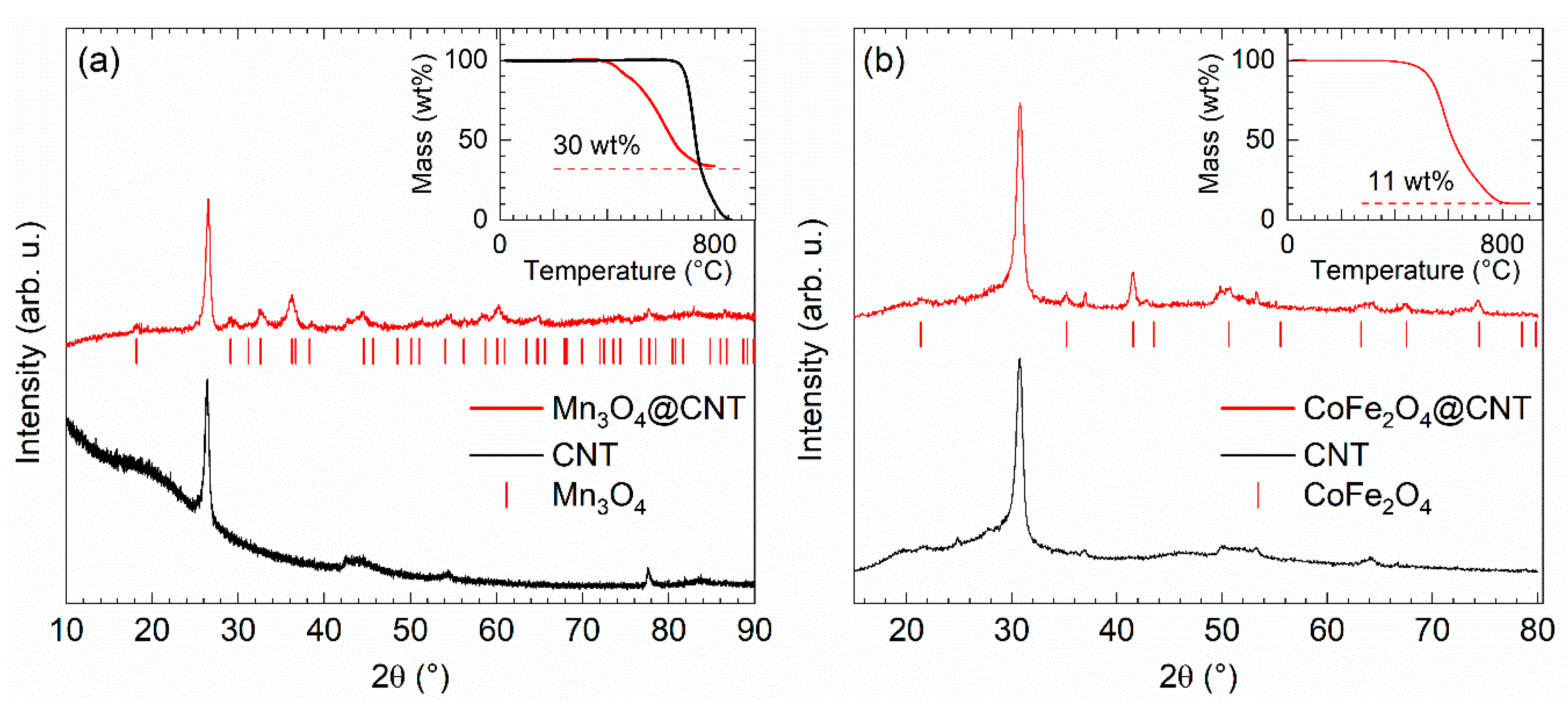
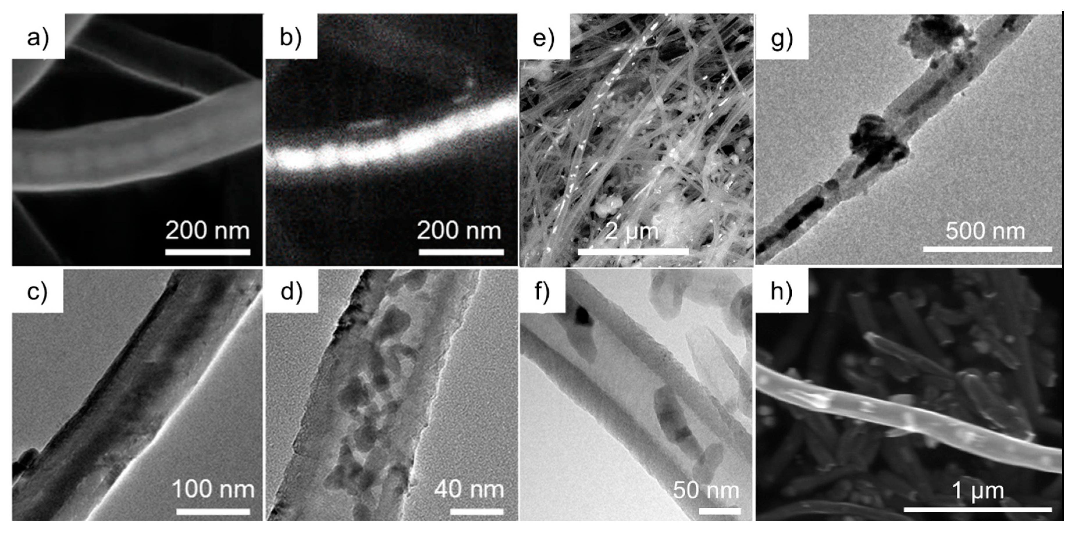
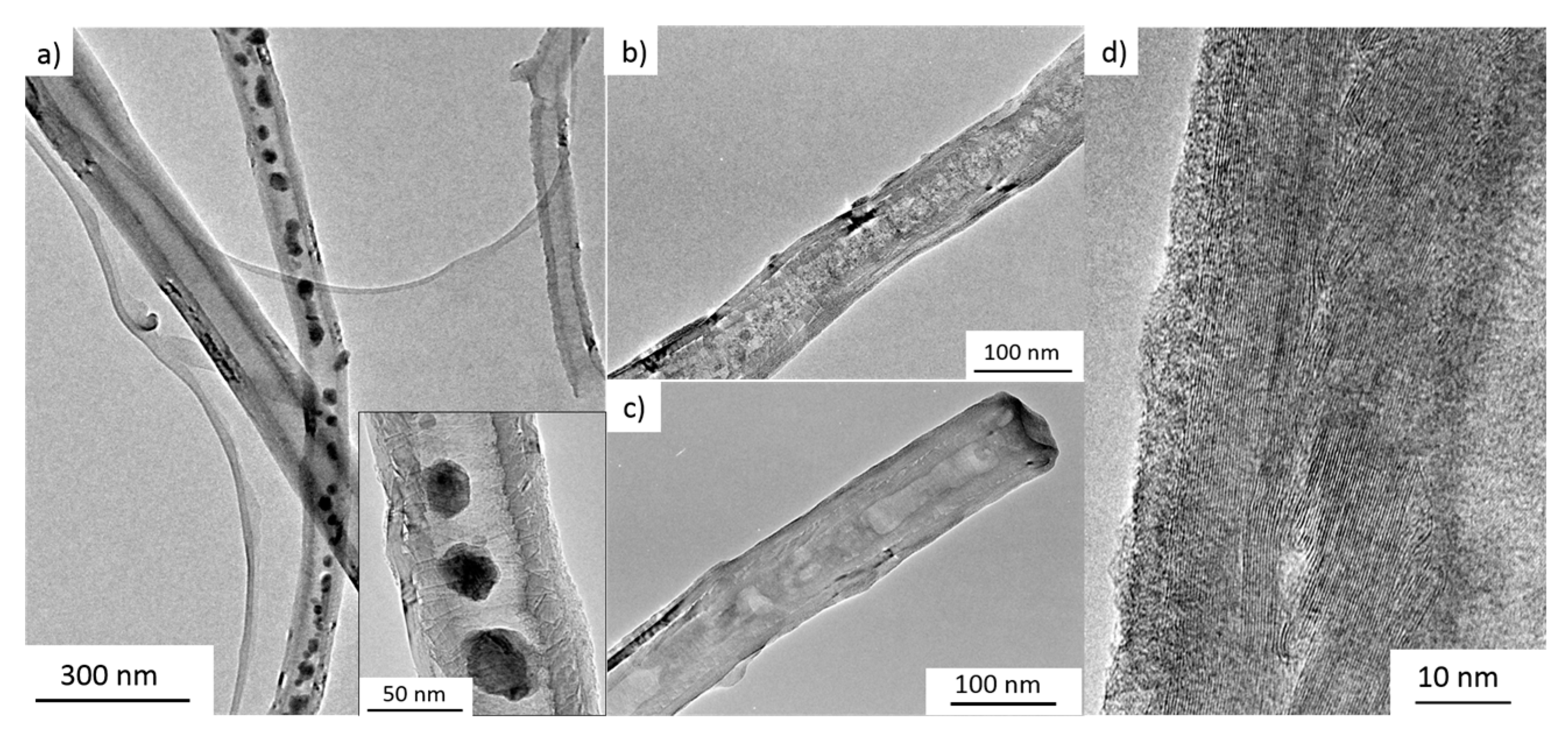
2. Synthesis and Characterization of Filled CNT
3. Electrochemical Studies
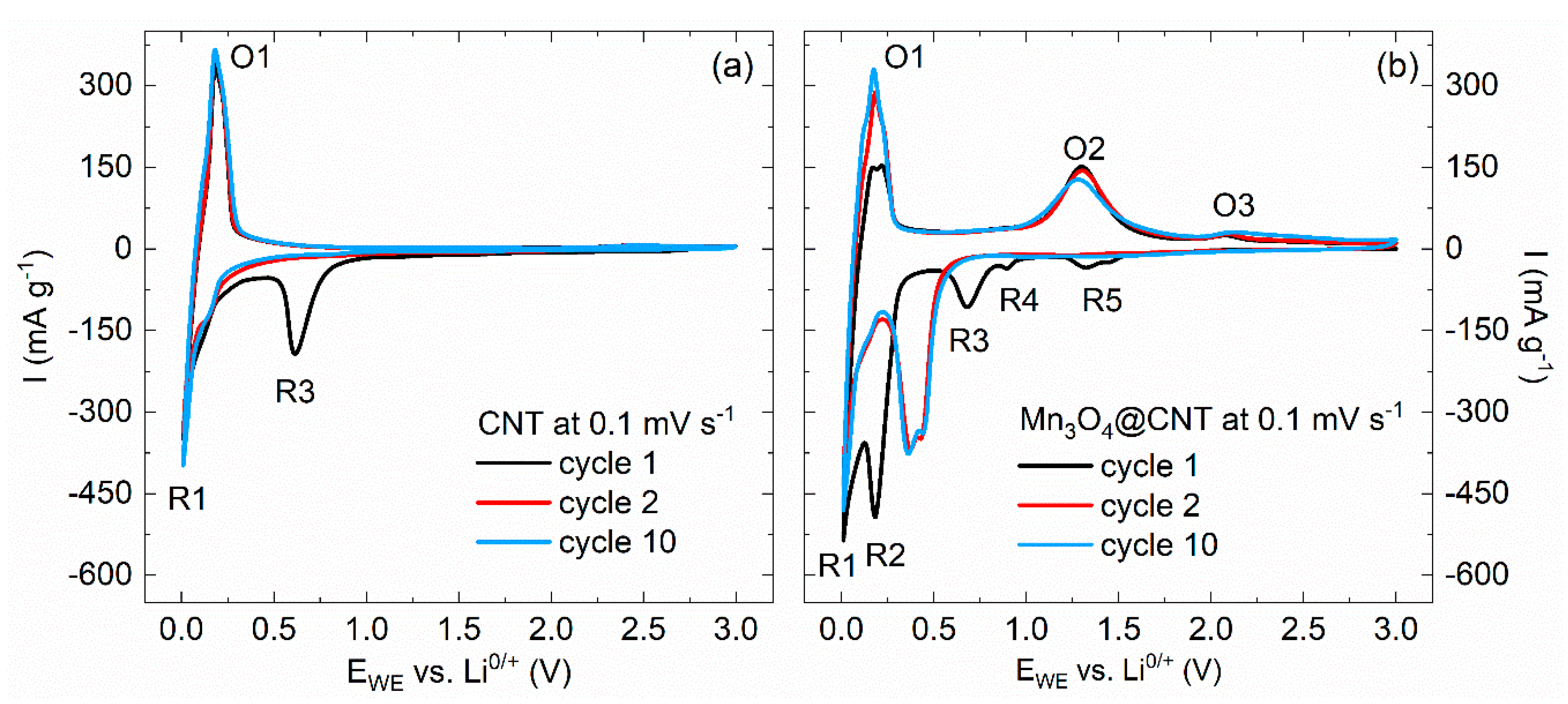
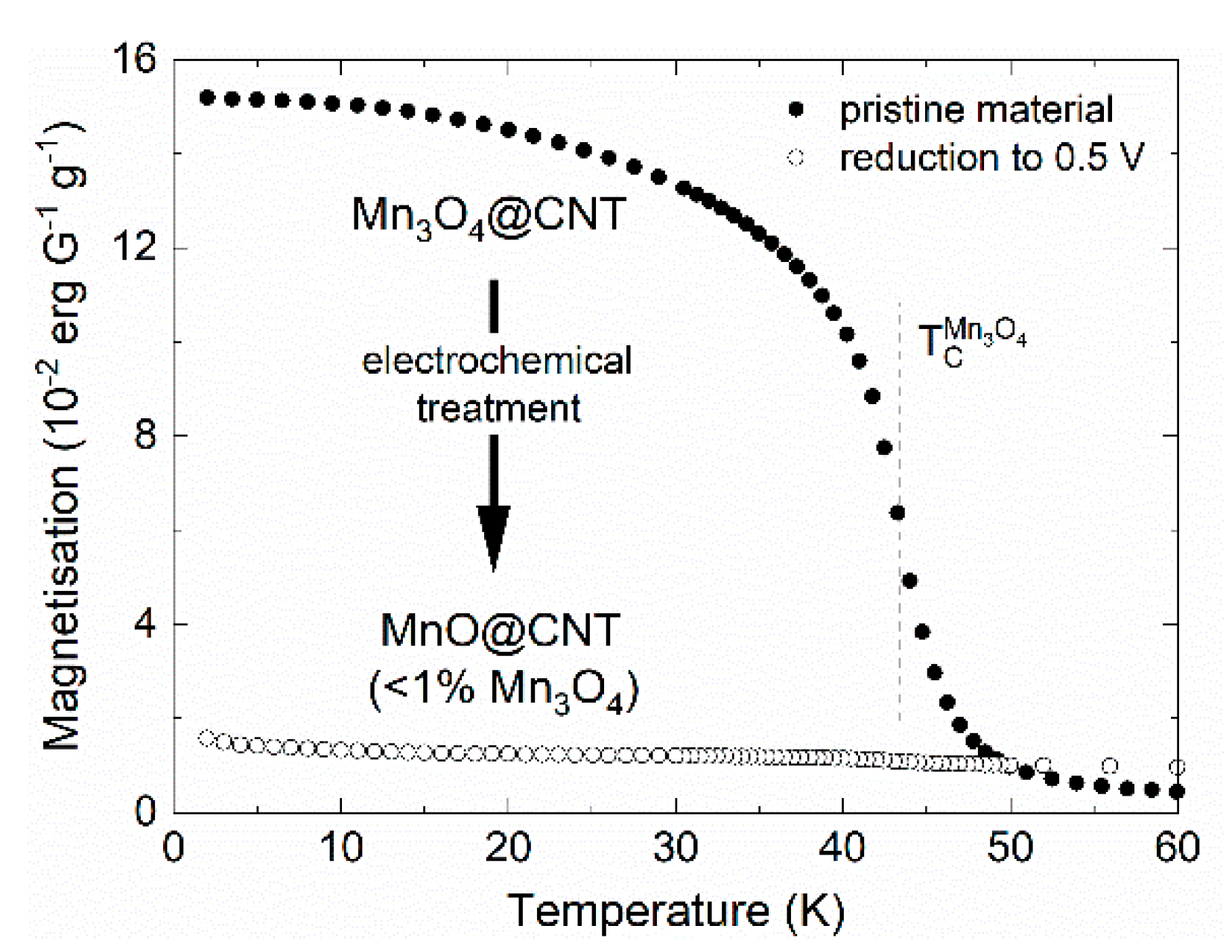
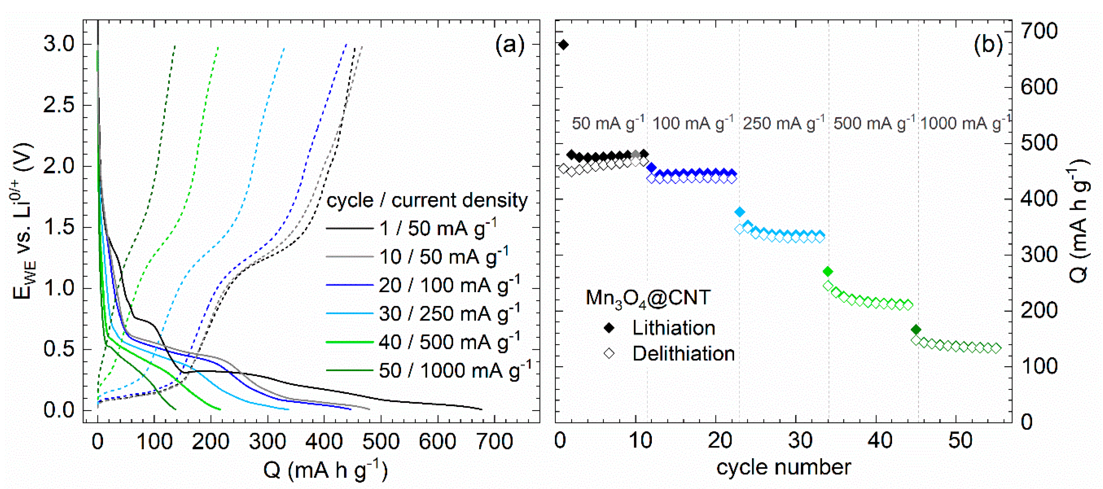
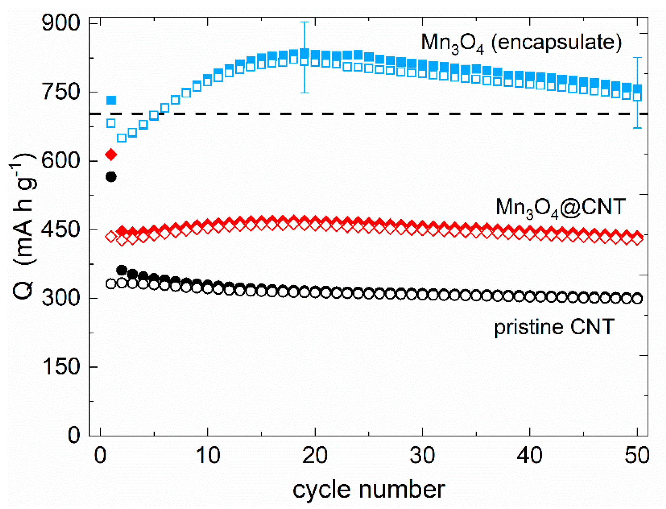
3.1. Mn3O4@CNT
- (A)
- Mn3(·II,·III)O4 + Li+ + e− → LiMn3(·II,·III)O4
- (B)
- LiMn3O4 + Li+ + e− → Li2O + 3·Mn(II)O
- (C)
- Mn(II)O + 2·Li+ + 2·e− ↔ Li2O + Mn(0)
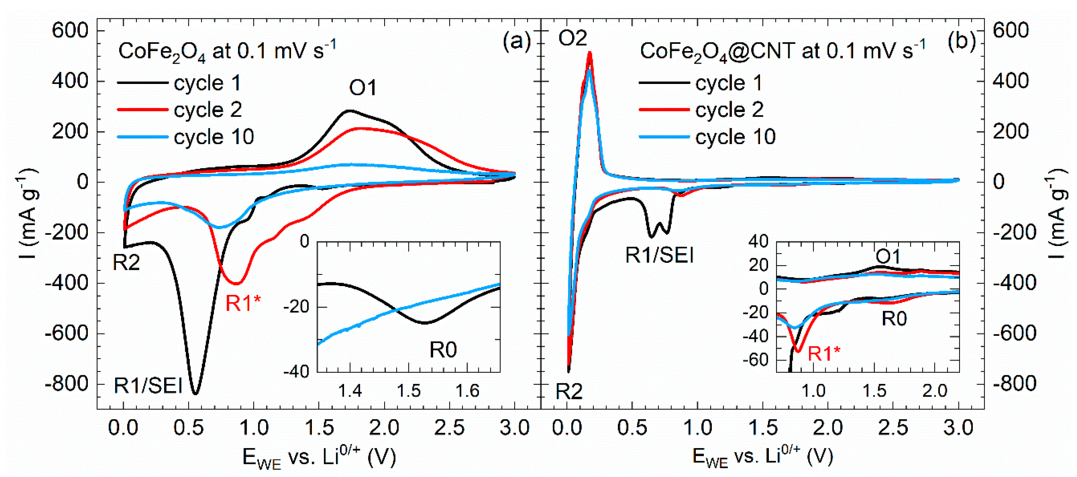
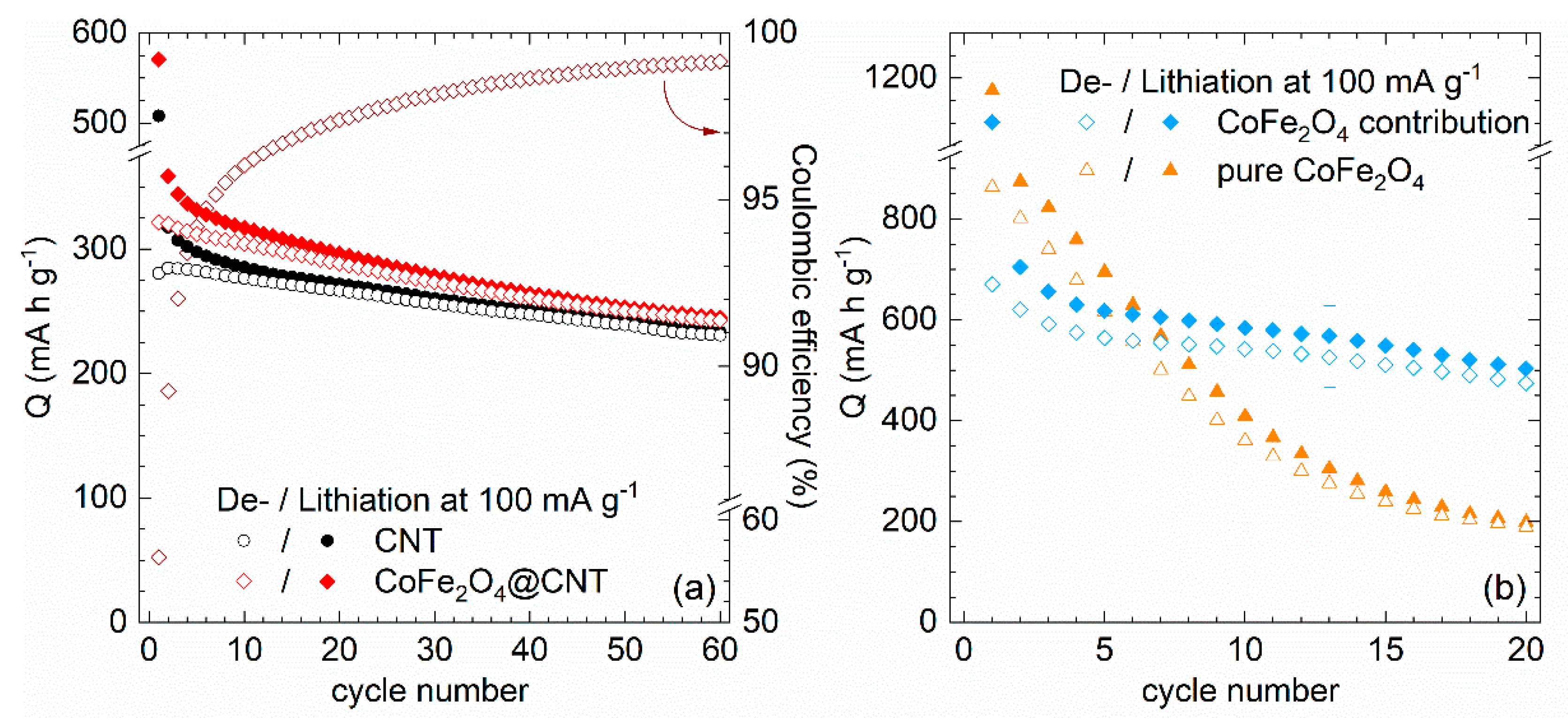
3.2. CoFe2O4@CNT
- (D)
- CoFe2O4 + 8 Li+ + 8 e− → Co + 2 Fe + 4 Li2O
- (E)
- Co + 2 Fe + 4 Li2O ↔ CoO + Fe2O3 + 8 Li+ + 8 e−
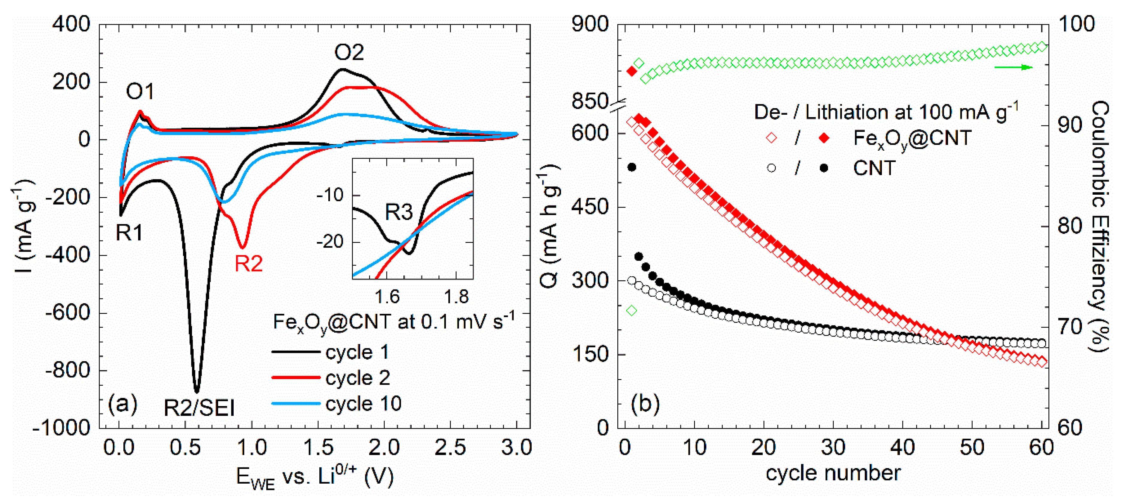
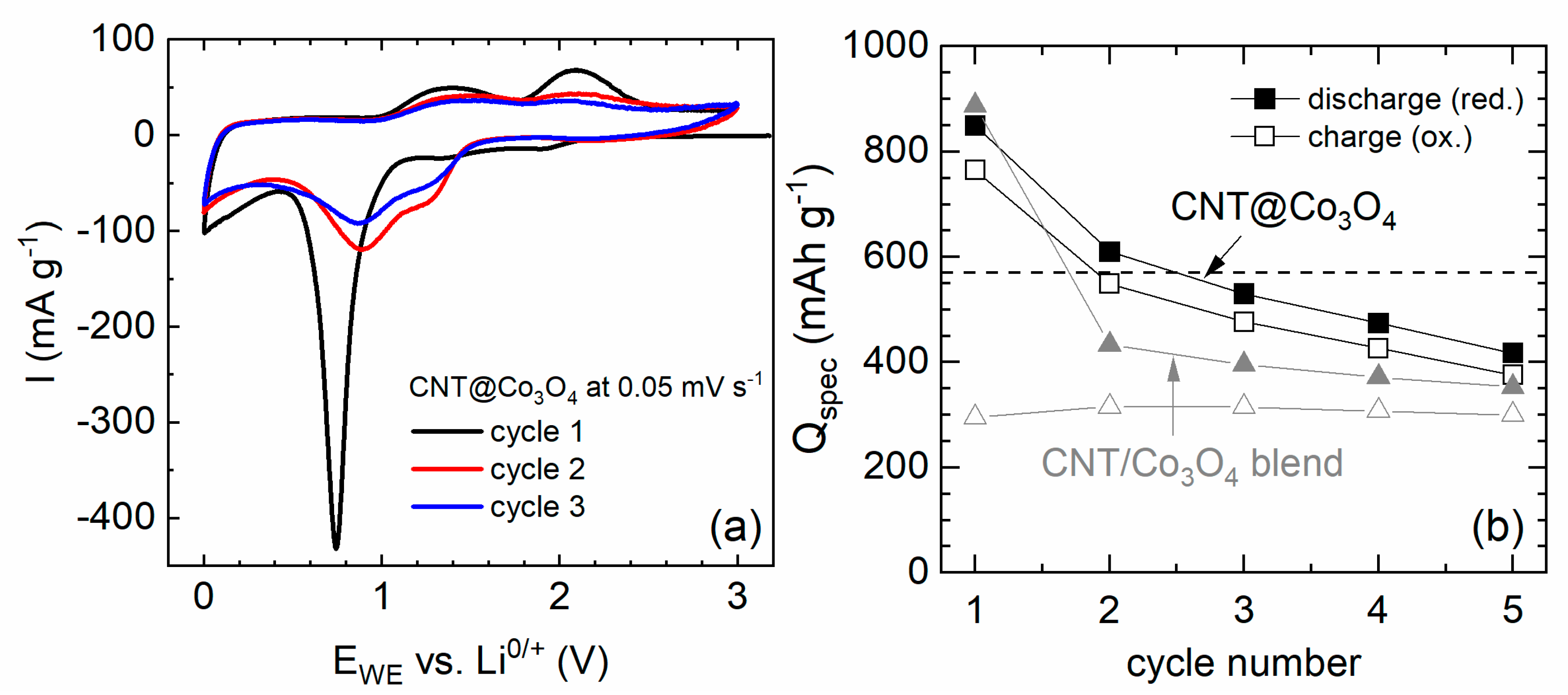
3.3. FexOy@CNT and CNT@Co3O4
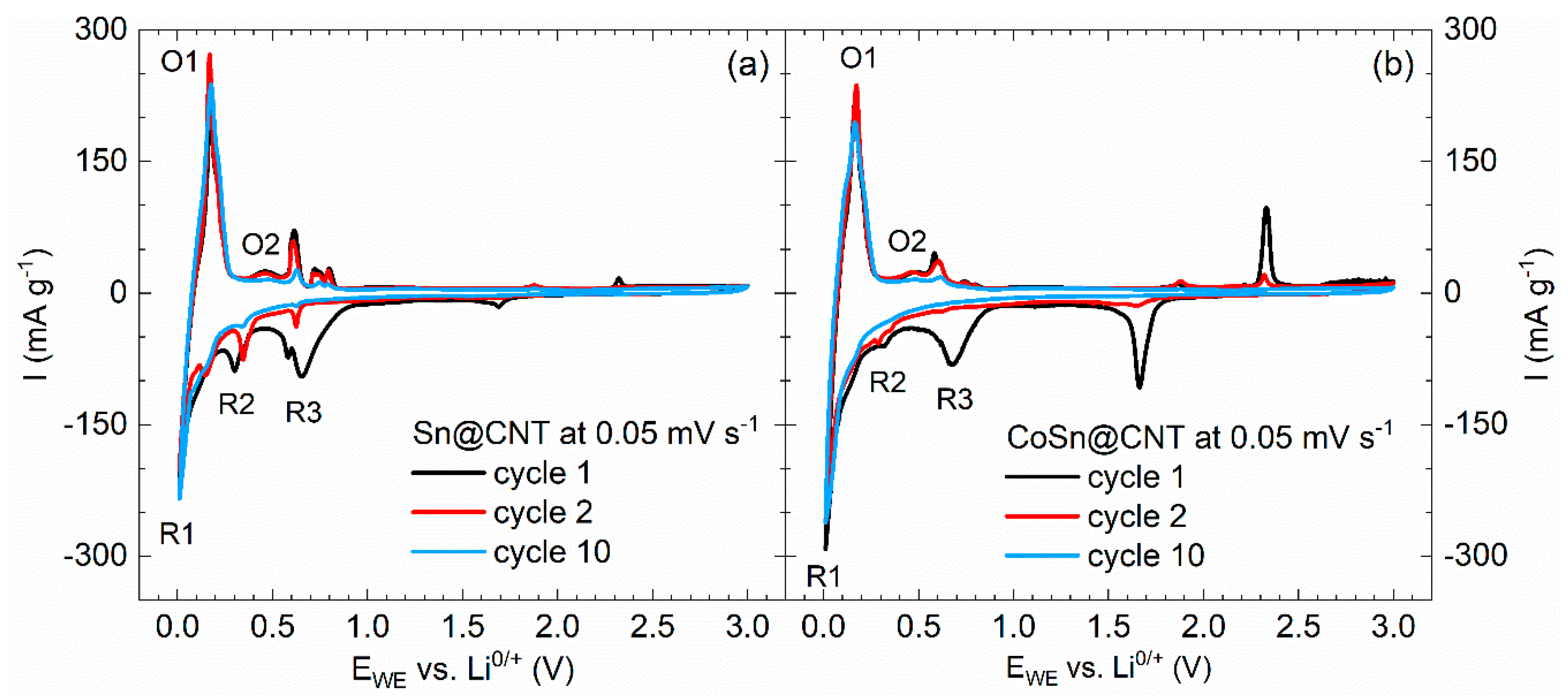
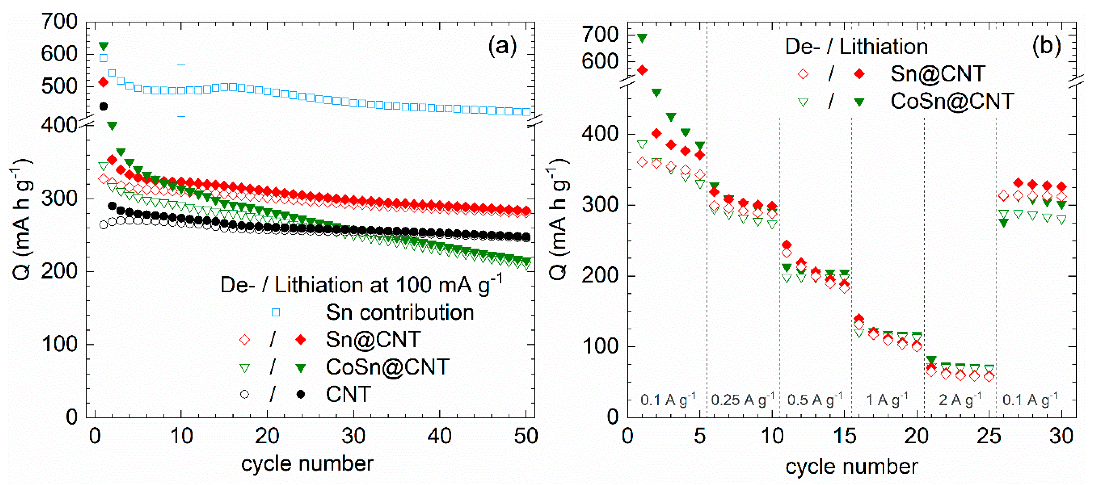
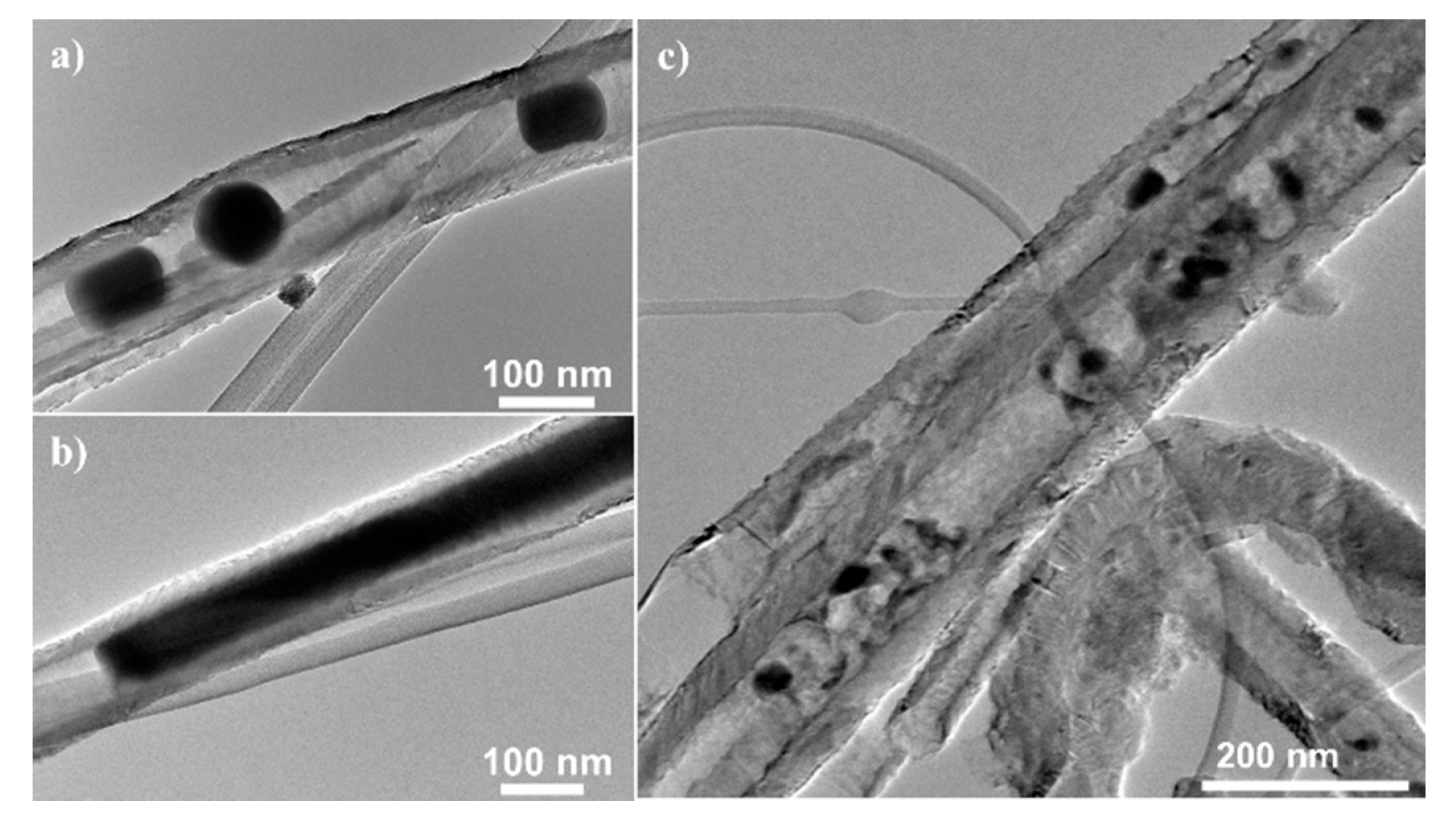
3.4. Sn@CNT and CoSn@CNT
4. Experimental Methods
4.1. Material Characterization
4.2. Electrochemical Measurements
5. Conclusions
Author Contributions
Funding
Acknowledgments
Conflicts of Interest
References
- Palacín, M.R. Recent advances in rechargeable battery materials: A chemist’s perspective. Chem. Soc. Rev. 2009, 38, 2565–2575. [Google Scholar] [CrossRef] [PubMed]
- Aravindan, V.; Lee, Y.-S.; Madhavi, S. Research Progress on Negative Electrodes for Practical Li-Ion Batteries: Beyond Carbonaceous Anodes. Adv. Energy Mater. 2015, 5, 1402225. [Google Scholar] [CrossRef]
- Mahmood, N.; Tang, T.; Hou, Y. Nanostructured Anode Materials for Lithium Ion Batteries: Progress, Challenge and Perspective. Adv. Energy Mater. 2016, 6, 1600374. [Google Scholar] [CrossRef]
- Deng, Y.; Wan, L.; Xie, Y.; Qin, X.; Chen, G. Recent advances in Mn-based oxides as anode materials for lithium ion batteries. RSC Adv. 2014, 4, 23914–23935. [Google Scholar] [CrossRef]
- Arico, A.S.; Bruce, P.; Scrosati, B.; Tarascon, J.-M.; van Schalkwijk, W. Nanostructured materials for advanced energy conversion and storage devices. Nat. Mater. 2005, 4, 366–377. [Google Scholar] [CrossRef]
- Nazar, L.F.; Goward, G.; Leroux, F.; Duncan, M.; Huang, H.; Kerr, T.; Gaubicher, J. Nanostructured materials for energy storage. Int. J. Inorg. Mater. 2001, 3, 191–200. [Google Scholar] [CrossRef]
- Armand, M.; Tarascon, J.-M. Building better batteries. Nature 2008, 451, 652–657. [Google Scholar] [CrossRef]
- Goriparti, S.; Miele, E.; de Angelis, F.; Di Fabrizio, E.; Proietti Zaccaria, R.; Capiglia, C. Review on recent progress of nanostructured anode materials for Li-ion batteries. J. Power Sources 2014, 257, 421–443. [Google Scholar] [CrossRef] [Green Version]
- Ji, L.; Lin, Z.; Alcoutlabi, M.; Zhang, X. Recent developments in nanostructured anode materials for rechargeable lithium-ion batteries. Energy Environ. Sci. 2011, 4, 2682–2699. [Google Scholar] [CrossRef]
- Huang, X.; Cui, S.; Chang, J.; Hallac, P.B.; Fell, C.R.; Luo, Y.; Metz, B.; Jiang, J.; Hurley, P.T.; Chen, J. A hierarchical tin/carbon composite as an anode for lithium-ion batteries with a long cycle life. Angew. Chem. Int. Ed. Engl. 2015, 54, 1490–1493. [Google Scholar] [CrossRef]
- Gao, G.; Le, Y.; Wu, H.B.; Lou, X.W.D. Hierarchical tubular structures constructed by carbon-coated α-Fe2O3 nanorods for highly reversible lithium storage. Small 2014, 10, 1741–1745. [Google Scholar] [CrossRef] [PubMed]
- Wang, P.-P.; Sun, H.; Ji, Y.; Li, W.; Wang, X. Three-dimensional assembly of single-layered MoS(2). Adv. Mater. 2014, 26, 964–969. [Google Scholar] [CrossRef] [PubMed]
- Li, Z.; Ottmann, A.; Zhang, T.; Sun, Q.; Meyer, H.-P.; Vaynzof, Y.; Xiang, J.; Klingeler, R. Preparation of hierarchical C@MoS2@C sandwiched hollow spheres for lithium ion batteries. J. Mater. Chem. A 2017, 5, 3987–3994. [Google Scholar] [CrossRef] [Green Version]
- Li, Z.; Ottmann, A.; Sun, Q.; Kast, A.K.; Wang, K.; Zhang, T.; Meyer, H.-P.; Backes, C.; Kübel, C.; Schröder, R.R.; et al. Hierarchical MoS 2 –carbon porous nanorods towards atomic interfacial engineering for high-performance lithium storage. J. Mater. Chem. A 2019, 7, 7553–7564. [Google Scholar] [CrossRef] [Green Version]
- Lou, X.W.; Chen, J.S.; Chen, P.; Archer, L.A. One-Pot Synthesis of Carbon-Coated SnO2 Nanocolloids with Improved Reversible Lithium Storage Properties. Chem. Mater. 2009, 21, 2868–2874. [Google Scholar] [CrossRef]
- Kang, T.-W.; Lim, H.-S.; Park, S.-J.; Sun, Y.-K.; Suh, K.-D. Fabrication of flower-like tin/carbon composite microspheres as long-lasting anode materials for lithium ion batteries. Mater. Chem. Phys. 2017, 185, 6–13. [Google Scholar] [CrossRef]
- Chen, X.; Xiao, T.; Wang, S.; Li, J.; Xiang, P.; Jiang, L.; Tan, X. Superior Li-ion storage performance of graphene decorated NiO nanowalls on Ni as anode for lithium ion batteries. Mater. Chem. Phys. 2019, 222, 31–36. [Google Scholar] [CrossRef]
- Sun, H.; Sun, X.; Hu, T.; Yu, M.; Lu, F.; Lian, J. Graphene-Wrapped Mesoporous Cobalt Oxide Hollow Spheres Anode for High-Rate and Long-Life Lithium Ion Batteries. J. Phys. Chem. C 2014, 118, 2263–2272. [Google Scholar] [CrossRef]
- Choi, S.H.; Ko, Y.N.; Jung, K.Y.; Kang, Y.C. Macroporous Fe3O4/carbon composite microspheres with a short Li+ diffusion pathway for the fast charge/discharge of lithium ion batteries. Chemistry 2014, 20, 11078–11083. [Google Scholar] [CrossRef]
- Lei, C.; Han, F.; Sun, Q.; Li, W.-C.; Lu, A.-H. Confined nanospace pyrolysis for the fabrication of coaxial Fe3O4@C hollow particles with a penetrated mesochannel as a superior anode for Li-ion batteries. Chemistry 2014, 20, 139–145. [Google Scholar] [CrossRef]
- Wu, C.; Li, X.; Li, W.; Li, B.; Wang, Y.; Wang, Y.; Xu, M.; Xing, L. Fe2O3 nanorods/carbon nanofibers composite: Preparation and performance as anode of high rate lithium ion battery. J. Power Sources 2014, 251, 85–91. [Google Scholar] [CrossRef]
- Zhang, S.; Zhu, L.; Song, H.; Chen, X.; Zhou, J. Enhanced electrochemical performance of MnO nanowire/graphene composite during cycling as the anode material for lithium-ion batteries. Nano Energy 2014, 10, 172–180. [Google Scholar] [CrossRef]
- Shi, X.; Zhang, S.; Chen, X.; Tang, T.; Klingeler, R.; Mijowska, E. Ultrathin NiO confined within hollow carbon sphere for efficient electrochemical energy storage. J. Alloys Compd. 2019, 797, 702–709. [Google Scholar] [CrossRef]
- Kan, J.; Wang, Y. Large and fast reversible Li-ion storages in Fe2O3-graphene sheet-on-sheet sandwich-like nanocomposites. Sci. Rep. 2013, 3, 3502. [Google Scholar] [CrossRef] [Green Version]
- Park, S.-K.; Jin, A.; Yu, S.-H.; Ha, J.; Jang, B.; Bong, S.; Woo, S.; Sung, Y.-E.; Piao, Y. In Situ Hydrothermal Synthesis of Mn3O4 Nanoparticles on Nitrogen-doped Graphene as High-Performance Anode materials for Lithium Ion Batteries. Electrochim. Acta 2014, 120, 452–459. [Google Scholar] [CrossRef]
- Zakharova, G.S.; Ottmann, A.; Möller, L.; Andreikov, E.I.; Fattakhova, Z.A.; Puzyrev, I.S.; Zhu, Q.; Thauer, E.; Klingeler, R. TiO2/C nanocomposites prepared by thermal annealing of titanium glycerolate as anode materials for lithium-ion batteries. J. Mater. Sci. 2018, 53. [Google Scholar] [CrossRef]
- Wenelska, K.; Ottmann, A.; Schneider, P.; Thauer, E.; Klingeler, R.; Mijowska, E. Hollow carbon sphere/metal oxide nanocomposites anodes for lithium-ion batteries. Energy 2016, 103, 100–106. [Google Scholar] [CrossRef] [Green Version]
- Guan, X.; Nai, J.; Zhang, Y.; Wang, P.; Yang, J.; Zheng, L.; Zhang, J.; Guo, L. CoO Hollow Cube/Reduced Graphene Oxide Composites with Enhanced Lithium Storage Capability. Chem. Mater. 2014, 26, 5958–5964. [Google Scholar] [CrossRef]
- Avogadro: An Open-Source Molecular Builder and Visualization Tool, 2.0. Available online: http://avogadro.cc/ (accessed on 18 January 2019).
- Ottmann, A. Nanostrukturierte Kohlenstoff-Komposite und Ammoniumvanadate als Elektrodenmaterialien für Lithium-Ionen-Batterien. Ph.D. Thesis, Ruprecht-Karls-Universität, Heidelberg, Germany, 2018. [Google Scholar]
- Dai, H. Carbon nanotubes: Opportunities and challenges. Surf. Sci. 2002, 500, 218–241. [Google Scholar] [CrossRef]
- Wenelska, K.; Neef, C.; Schlestein, L.; Klingeler, R.; Kalenczuk, R.J.; Mijowska, E. Carbon nanotubes decorated by mesoporous cobalt oxide as electrode material for lithium-ion batteries. Chem. Phys. Lett. 2015, 635, 185–189. [Google Scholar] [CrossRef]
- Zhang, X.; Zhou, Y.; Mao, Y.; Wei, M.; Chu, W.; Huang, K. Rapid synthesis of ultrafine NiCo2O4 nanoparticles loaded carbon nanotubes for lithium ion battery anode materials. Chem. Phys. Lett. 2019, 715, 278–283. [Google Scholar] [CrossRef]
- Wen, Z.; Ci, S.; Mao, S.; Cui, S.; He, Z.; Chen, J. CNT@TiO2 nanohybrids for high-performance anode of lithium-ion batteries. Nanoscale Res. Lett. 2013, 8, 499. [Google Scholar] [CrossRef] [PubMed] [Green Version]
- Bhaskar, A.; Deepa, M.; Narasinga Rao, T. MoO2/multiwalled carbon nanotubes (MWCNT) hybrid for use as a Li-ion battery anode. ACS Appl. Mater. Interfaces 2013, 5, 2555–2566. [Google Scholar] [CrossRef] [PubMed]
- Poizot, P.; Laruelle, S.; Grugeon, S.; Dupont, L.; Tarascon, J.M. Nano-sized transition-metal oxides as negative-electrode materials for lithium-ion batteries. Nature 2000, 407, 496–499. [Google Scholar] [CrossRef] [PubMed]
- Winter, M.; Besenhard, J.O.; Spahr, M.E.; Novák, P. Insertion Electrode Materials for Rechargeable Lithium Batteries. Adv. Mater. 1998, 10, 725–763. [Google Scholar] [CrossRef]
- Tsang, S.C.; Chen, Y.K.; Harris, P.J.F.; Green, M.L.H. A simple chemical method of opening and filling carbon nanotubes. Nature 1994, 159–162. [Google Scholar] [CrossRef]
- Gellesch, M.; Dimitrakopoulou, M.; Scholz, M.; Blum, C.G.F.; Schulze, M.; van den Brink, J.; Hampel, S.; Wurmehl, S.; Büchner, B. Facile Nanotube-Assisted Synthesis of Ternary Intermetallic Nanocrystals of the Ferromagnetic Heusler Phase Co2FeGa: Supporting Information. Cryst. Growth Des. 2013, 13, 2707–2710. [Google Scholar] [CrossRef]
- Al Khabouri, S.; Al Harthi, S.; Maekawa, T.; Nagaoka, Y.; Elzain, M.E.; Al Hinai, A.; Al-Rawas, A.D.; Gismelseed, A.M.; Yousif, A.A. Composition, Electronic and Magnetic Investigation of the Encapsulated ZnFe2O4 Nanoparticles in Multiwall Carbon Nanotubes Containing Ni Residuals. Nanoscale Res. Lett. 2015, 10, 262. [Google Scholar] [CrossRef] [Green Version]
- Ghunaim, R.; Damm, C.; Wolf, D.; Lubk, A.; Büchner, B.; Mertig, M.; Hampel, S. Fe1-xNix Alloy Nanoparticles Encapsulated Inside Carbon Nanotubes: Controlled Synthesis, Structure and Magnetic Properties. Nanomaterials 2018, 8, 576. [Google Scholar] [CrossRef] [Green Version]
- Ghunaim, R.; Eckert, V.; Scholz, M.; Gellesch, M.; Wurmehl, S.; Damm, C.; Büchner, B.; Mertig, M.; Hampel, S. Carbon nanotube-assisted synthesis of ferromagnetic Heusler nanoparticles of Fe 3 Ga (Nano-Galfenol). J. Mater. Chem. C 2018, 6, 1255–1263. [Google Scholar] [CrossRef]
- Ghunaim, R.; Scholz, M.; Damm, C.; Rellinghaus, B.; Klingeler, R.; Büchner, B.; Mertig, M.; Hampel, S. Single-crystalline FeCo nanoparticle-filled carbon nanotubes: Synthesis, structural characterization and magnetic properties. Beilstein J. Nanotechnol. 2018, 9, 1024–1034. [Google Scholar] [CrossRef] [Green Version]
- Haft, M.; Grönke, M.; Gellesch, M.; Wurmehl, S.; Büchner, B.; Mertig, M.; Hampel, S. Tailored nanoparticles and wires of Sn, Ge and Pb inside carbon nanotubes. Carbon 2016, 101, 352–360. [Google Scholar] [CrossRef]
- Ottmann, A.; Scholz, M.; Haft, M.; Thauer, E.; Schneider, P.; Gellesch, M.; Nowka, C.; Wurmehl, S.; Hampel, S.; Klingeler, R. Electrochemical Magnetization Switching and Energy Storage in Manganese Oxide filled Carbon Nanotubes. Sci. Rep. 2017, 7, 13625. [Google Scholar] [CrossRef] [PubMed]
- Jarosch, D. Crystal structure refinement and reflectance measurements of hausmannite, Mn3O4. Mineral. Petrol. 1987, 37, 15–23. [Google Scholar] [CrossRef]
- Ferreira, T.A.S.; Waerenborgh, J.C.; Mendonça, M.H.R.M.; Nunes, M.R.; Costa, F.M. Structural and morphological characterization of FeCo2O4 and CoFe2O4 spinels prepared by a coprecipitation method. Solid State Sci. 2003, 5, 383–392. [Google Scholar] [CrossRef]
- Kapoor, A.; Singh, N.; Dey, A.B.; Nigam, A.K.; Bajpai, A. 3d transition metals and oxides within carbon nanotubes by co-pyrolysis of metallocene & camphor: High filling efficiency and self-organized structures. Carbon 2018, 132, 733–745. [Google Scholar] [CrossRef] [Green Version]
- Heider, R. Nanoskalige Sn-Co-Verbindungen Durch Füllen von CNT. Master Thesis, BTU Cottbus-Senftenberg, Cottbus, Germany, 2015. [Google Scholar]
- Frackowiak, E.; Béguin, F. Electrochemical storage of energy in carbon nanotubes and nanostructured carbons. Carbon 2002, 40, 1775–1787. [Google Scholar] [CrossRef]
- Chew, S.Y.; Ng, S.H.; Wang, J.; Novák, P.; Krumeich, F.; Chou, S.L.; Chen, J.; Liu, H.K. Flexible free-standing carbon nanotube films for model lithium-ion batteries. Carbon 2009, 47, 2976–2983. [Google Scholar] [CrossRef]
- Xiong, Z.; Yun, Y.; Jin, H.-J. Applications of Carbon Nanotubes for Lithium Ion Battery Anodes. Materials 2013, 6, 1138–1158. [Google Scholar] [CrossRef] [Green Version]
- Fang, X.; Lu, X.; Guo, X.; Mao, Y.; Hu, Y.-S.; Wang, J.; Wang, Z.; Wu, F.; Liu, H.; Chen, L. Electrode reactions of manganese oxides for secondary lithium batteries. Electrochem. Commun. 2010, 12, 1520–1523. [Google Scholar] [CrossRef]
- Zhong, K.; Xia, X.; Zhang, B.; Li, H.; Wang, Z.; Chen, L. MnO powder as anode active materials for lithium ion batteries. J. Power Sources 2010, 195, 3300–3308. [Google Scholar] [CrossRef]
- Tyler, R.W. The Magnetic Susceptibility of MnO as a Function of the Temperature. Phys. Rev. 1933, 44, 776–777. [Google Scholar] [CrossRef]
- Bai, Z.; Zhang, X.; Zhang, Y.; Guo, C.; Tang, B. Facile synthesis of mesoporous Mn3O4 nanorods as a promising anode material for high performance lithium-ion batteries. J. Mater. Chem. A 2014, 2, 16755–16760. [Google Scholar] [CrossRef]
- Li, L.; Guo, Z.; Du, A.; Liu, H. Rapid microwave-assisted synthesis of Mn3O4–graphene nanocomposite and its lithium storage properties. J. Mater. Chem. 2012, 22, 3600–3605. [Google Scholar] [CrossRef] [Green Version]
- Wang, Z.-H.; Yuan, L.-X.; Shao, Q.-G.; Huang, F.; Huang, Y.-H. Mn3O4 nanocrystals anchored on multi-walled carbon nanotubes as high-performance anode materials for lithium-ion batteries. Mater. Lett. 2012, 80, 110–113. [Google Scholar] [CrossRef]
- Luo, S.; Wu, H.; Wu, Y.; Jiang, K.; Wang, J.; Fan, S. Mn3O4 nanoparticles anchored on continuous carbon nanotube network as superior anodes for lithium ion batteries. J. Power Sources 2014, 249, 463–469. [Google Scholar] [CrossRef]
- Lavela, P.; Ortiz, G.F.; Tirado, J.L.; Zhecheva, E.; Stoyanova, R.; Ivanova, S. High-Performance Transition Metal Mixed Oxides in Conversion Electrodes: A Combined Spectroscopic and Electrochemical Study. J. Phys. Chem. C 2007, 111, 14238–14246. [Google Scholar] [CrossRef]
- De las Casas, C.; Li, W. A review of application of carbon nanotubes for lithium ion battery anode material. J. Power Sources 2012, 208, 74–85. [Google Scholar] [CrossRef]
- Varzi, A.; Täubert, C.; Wohlfahrt-Mehrens, M.; Kreis, M.; Schütz, W. Study of multi-walled carbon nanotubes for lithium-ion battery electrodes. J. Power Sources 2011, 196, 3303–3309. [Google Scholar] [CrossRef]
- Chu, Y.-Q.; Fu, Z.-W.; Qin, Q.-Z. Cobalt ferrite thin films as anode material for lithium ion batteries. Electrochim. Acta 2004, 49, 4915–4921. [Google Scholar] [CrossRef]
- Verma, P.; Maire, P.; Novák, P. A review of the features and analyses of the solid electrolyte interphase in Li-ion batteries. Electrochim. Acta 2010, 55, 6332–6341. [Google Scholar] [CrossRef]
- Gnanamuthu, R.; Lee, C.W. Electrochemical properties of Super P carbon black as an anode active material for lithium-ion batteries. Mater. Chem. Phys. 2011, 130, 831–834. [Google Scholar] [CrossRef]
- Cabana, J.; Monconduit, L.; Larcher, D.; Palacín, M.R. Beyond intercalation-based Li-ion batteries: The state of the art and challenges of electrode materials reacting through conversion reactions. Adv. Mater. 2010, 22, E170–E192. [Google Scholar] [CrossRef] [PubMed]
- Wang, Y.; Su, D.; Ung, A.; Ahn, J.H.; Wang, G. Hollow CoFe2O4 nanospheres as a high capacity anode material for lithium ion batteries. Nanotechnology 2012, 23, 55402. [Google Scholar] [CrossRef] [PubMed]
- Wu, L.; Xiao, Q.; Li, Z.; Lei, G.; Zhang, P.; Wang, L. CoFe2O4/C composite fibers as anode materials for lithium-ion batteries with stable and high electrochemical performance. Solid State Ion. 2012, 215, 24–28. [Google Scholar] [CrossRef]
- Wang, L.; Zhuo, L.; Cheng, H.; Zhang, C.; Zhao, F. Porous carbon nanotubes decorated with nanosized cobalt ferrite as anode materials for high-performance lithium-ion batteries. J. Power Sources 2015, 283, 289–299. [Google Scholar] [CrossRef]
- Zhang, Z.; Wang, Y.; Zhang, M.; Tan, Q.; Lv, X.; Zhong, Z.; Su, F. Mesoporous CoFe2O4 nanospheres cross-linked by carbon nanotubes as high-performance anodes for lithium-ion batteries. J. Mater. Chem. A 2013, 1, 7444–7450. [Google Scholar] [CrossRef]
- Ren, S.; Zhao, X.; Chen, R.; Fichtner, M. A facile synthesis of encapsulated CoFe2O4 into carbon nanofibres and its application as conversion anodes for lithium ion batteries. J. Power Sources 2014, 260, 205–210. [Google Scholar] [CrossRef]
- Zhang, L.; Wei, T.; Jiang, Z.; Liu, C.; Jiang, H.; Chang, J.; Sheng, L.; Zhou, Q.; Yuan, L.; Fan, Z. Electrostatic interaction in electrospun nanofibers: Double-layer carbon protection of CoFe2O4 nanosheets enabling ultralong-life and ultrahigh-rate lithium ion storage. Nano Energy 2018, 48, 238–247. [Google Scholar] [CrossRef]
- Laruelle, S.; Grugeon, S.; Poizot, P.; Dollé, M.; Dupont, L.; Tarascon, J.-M. On the Origin of the Extra Electrochemical Capacity Displayed by MO/Li Cells at Low Potential. J. Electrochem. Soc. 2002, 149, A627–A634. [Google Scholar] [CrossRef]
- Jamnik, J.; Maier, J. Nanocrystallinity effects in lithium battery materials. Phys. Chem. Chem. Phys. 2003, 5, 5215. [Google Scholar] [CrossRef]
- Larcher, D.; Bonnin, D.; Cortes, R.; Rivals, I.; Personnaz, L.; Tarascon, J.-M. Combined XRD, EXAFS, and Mössbauer Studies of the Reduction by Lithium of α-Fe2O3 with Various Particle Sizes. J. Electrochem. Soc. 2003, 150, A1643–A1650. [Google Scholar] [CrossRef]
- Larcher, D.; Masquelier, C.; Bonnin, D.; Chabre, Y.; Masson, V.; Leriche, J.-B.; Tarascon, J.-M. Effect of Particle Size on Lithium Intercalation into α-Fe2O3. J. Electrochem. Soc. 2003, 150, A133–A139. [Google Scholar] [CrossRef]
- Morales, J.; Sánchez, L.; Martín, F.; Berry, F.; Ren, X. Synthesis and Characterization of Nanometric Iron and Iron-Titanium Oxides by Mechanical Milling. J. Electrochem. Soc. 2005, 152, A1748–A1754. [Google Scholar] [CrossRef] [Green Version]
- Cherian, C.T.; Sundaramurthy, J.; Kalaivani, M.; Ragupathy, P.; Kumar, P.S.; Thavasi, V.; Reddy, M.V.; Sow, C.H.; Mhaisalkar, S.G.; Ramakrishna, S.; et al. Electrospun α-Fe2O3 nanorods as a stable, high capacity anode material for Li-ion batteries. J. Mater. Chem. 2012, 22, 12198–12204. [Google Scholar] [CrossRef]
- Hariharan, S.; Saravanan, K.; Balaya, P. Lithium Storage Using Conversion Reaction in Maghemite and Hematite. Electrochem. Solid State Lett. 2010, 13, A132–A134. [Google Scholar] [CrossRef]
- Thackeray, M.M. Spinel Electrodes for Lithium Batteries. J. Am. Ceram. Soc. 1999, 82, 3347–3354. [Google Scholar] [CrossRef]
- Thackeray, M.M.; David, W.I.F.; Goodenough, J.B. Structural characterization of the lithiated iron oxides LixFe3O4 and LixFe2O3 (0<x<2). Mater. Res. Bull. 1982, 17, 785–793. [Google Scholar] [CrossRef]
- Xu, J.-S.; Zhu, Y.-J. Monodisperse Fe3O4 and γ-Fe2O3 magnetic mesoporous microspheres as anode materials for lithium-ion batteries. ACS Appl. Mater. Interfaces 2012, 4, 4752–4757. [Google Scholar] [CrossRef]
- Yuan, S.; Zhou, Z.; Li, G. Structural evolution from mesoporous α-Fe2O3 to Fe3O4@C and γ-Fe2O3 nanospheres and their lithium storage performances. CrystEngComm 2011, 13, 4709–4713. [Google Scholar] [CrossRef]
- Yan, N.; Zhou, X.; Li, Y.; Wang, F.; Zhong, H.; Wang, H.; Chen, Q. Fe2O3 Nanoparticles Wrapped in Multi-walled Carbon Nanotubes With Enhanced Lithium Storage Capability. Sci. Rep. 2013, 3, 3392. [Google Scholar] [CrossRef] [PubMed] [Green Version]
- Zhuo, L.; Wu, Y.; Ming, J.; Wang, L.; Yu, Y.; Zhang, X.; Zhao, F. Facile synthesis of a Co3O4 –carbon nanotube composite and its superior performance as an anode material for Li-ion batteries. J. Mater. Chem. A 2013, 1, 1141–1147. [Google Scholar] [CrossRef]
- Xu, M.; Wang, F.; Zhang, Y.; Yang, S.; Zhao, M.; Song, X. Co3O4-carbon nanotube heterostructures with bead-on-string architecture for enhanced lithium storage performance. Nanoscale 2013, 5, 8067–8072. [Google Scholar] [CrossRef] [PubMed] [Green Version]
- Obrovac, M.N.; Chevrier, V.L. Alloy negative electrodes for Li-ion batteries. Chem. Rev. 2014, 114, 11444–11502. [Google Scholar] [CrossRef]
- Wu, S.; Han, C.; Iocozzia, J.; Lu, M.; Ge, R.; Xu, R.; Lin, Z. Germanium-Based Nanomaterials for Rechargeable Batteries. Angew. Chem. Int. Ed. 2016, 55, 7898–7922. [Google Scholar] [CrossRef] [PubMed]
- Srajer, G.; Lewis, L.H.; Bader, S.D.; Epstein, A.J.; Fadley, C.S.; Fullerton, E.E.; Hoffmann, A.; Kortright, J.B.; Krishnan, K.M.; Majetich, S.A.; et al. Advances in nanomagnetism via X-ray techniques. J. Magn. Magn. Mater. 2006, 307, 1–31. [Google Scholar] [CrossRef]
- Goward, G.R.; Taylor, N.J.; Souza, D.C.S.; Nazar, L.F. The true crystal structure of Li17M4 (M=Ge, Sn, Pb)—revised from Li22M5. J. Alloys Compd. 2001, 329, 82–91. [Google Scholar] [CrossRef]
- Yin, F.; Su, X.; Li, Z.; Wang, J. Thermodynamic assessment of the Li–Sn (Lithium–Tin) system. J. Alloys Compd. 2005, 393, 105–108. [Google Scholar] [CrossRef]
- Todd, A.D.W.; Mar, R.E.; Dahn, J.R. Combinatorial Study of Tin-Transition Metal Alloys as Negative Electrodes for Lithium-Ion Batteries. J. Electrochem. Soc. 2006, 153, A1998–A2005. [Google Scholar] [CrossRef]
- Zhang, J.-j.; Xia, Y.-y. Co-Sn Alloys as Negative Electrode Materials for Rechargeable Lithium Batteries. J. Electrochem. Soc. 2006, 153, A1466–A1471. [Google Scholar] [CrossRef]
- Courtney, I.A.; Dahn, J.R. Electrochemical and In Situ X-Ray Diffraction Studies of the Reaction of Lithium with Tin Oxide Composites. J. Electrochem. Soc. 1997, 144, 2045–2052. [Google Scholar] [CrossRef]
- Ionica-Bousquet, C.M.; Lippens, P.E.; Aldon, L.; Olivier-Fourcade, J.; Jumas, J.C. In situ 119Sn Mössbauer Effect Study of Li−CoSn2 Electrochemical System. Chem. Mater. 2006, 18, 6442–6447. [Google Scholar] [CrossRef]
- Wang, Y.; Wu, M.; Jiao, Z.; Lee, J.Y. Sn@CNT and Sn@C@CNT nanostructures for superior reversible lithium ion storage. Chem. Mater. 2009, 21, 3210–3215. [Google Scholar] [CrossRef]
- Zakharova, G.S.; Thauer, E.; Wegener, S.A.; Nölke, J.-H.; Zhu, Q.; Klingeler, R. Hydrothermal microwave-assisted synthesis of Li3VO4 as an anode for lithium-ion battery. J. Solid State Electrochem. 2019, 23, 2205–2212. [Google Scholar] [CrossRef]


© 2020 by the authors. Licensee MDPI, Basel, Switzerland. This article is an open access article distributed under the terms and conditions of the Creative Commons Attribution (CC BY) license (http://creativecommons.org/licenses/by/4.0/).
Share and Cite
Thauer, E.; Ottmann, A.; Schneider, P.; Möller, L.; Deeg, L.; Zeus, R.; Wilhelmi, F.; Schlestein, L.; Neef, C.; Ghunaim, R.; et al. Filled Carbon Nanotubes as Anode Materials for Lithium-Ion Batteries. Molecules 2020, 25, 1064. https://doi.org/10.3390/molecules25051064
Thauer E, Ottmann A, Schneider P, Möller L, Deeg L, Zeus R, Wilhelmi F, Schlestein L, Neef C, Ghunaim R, et al. Filled Carbon Nanotubes as Anode Materials for Lithium-Ion Batteries. Molecules. 2020; 25(5):1064. https://doi.org/10.3390/molecules25051064
Chicago/Turabian StyleThauer, Elisa, Alexander Ottmann, Philip Schneider, Lucas Möller, Lukas Deeg, Rouven Zeus, Florian Wilhelmi, Lucas Schlestein, Christoph Neef, Rasha Ghunaim, and et al. 2020. "Filled Carbon Nanotubes as Anode Materials for Lithium-Ion Batteries" Molecules 25, no. 5: 1064. https://doi.org/10.3390/molecules25051064