Study on the Mechanical Properties and Strengthening Mechanism of Interface-Modified Carbon Fiber Mesh Reinforced Cement-Based Composites with SCA&HMC

Abstract
:1. Introduction
2. Research Contents and Methods
2.1. Materials
2.2. Preparation of Specimens
2.2.1. Surface Modification of Carbon Fabric
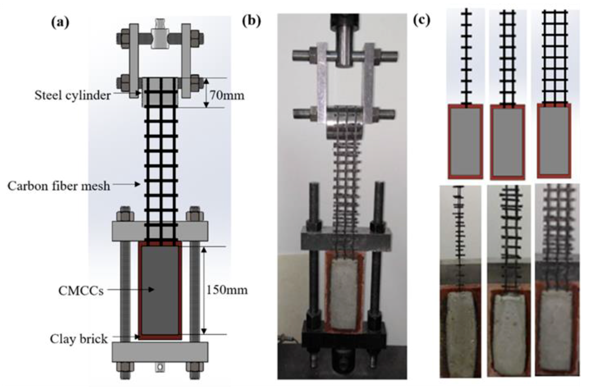
2.2.2. Preparation of the Double Shear Test Specimens
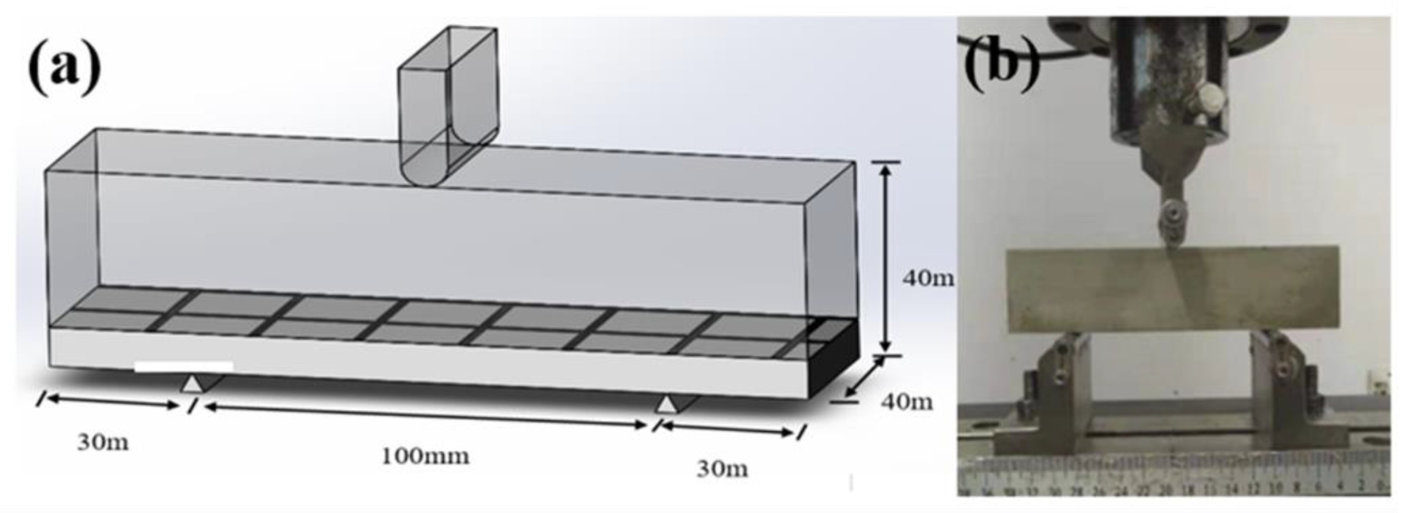
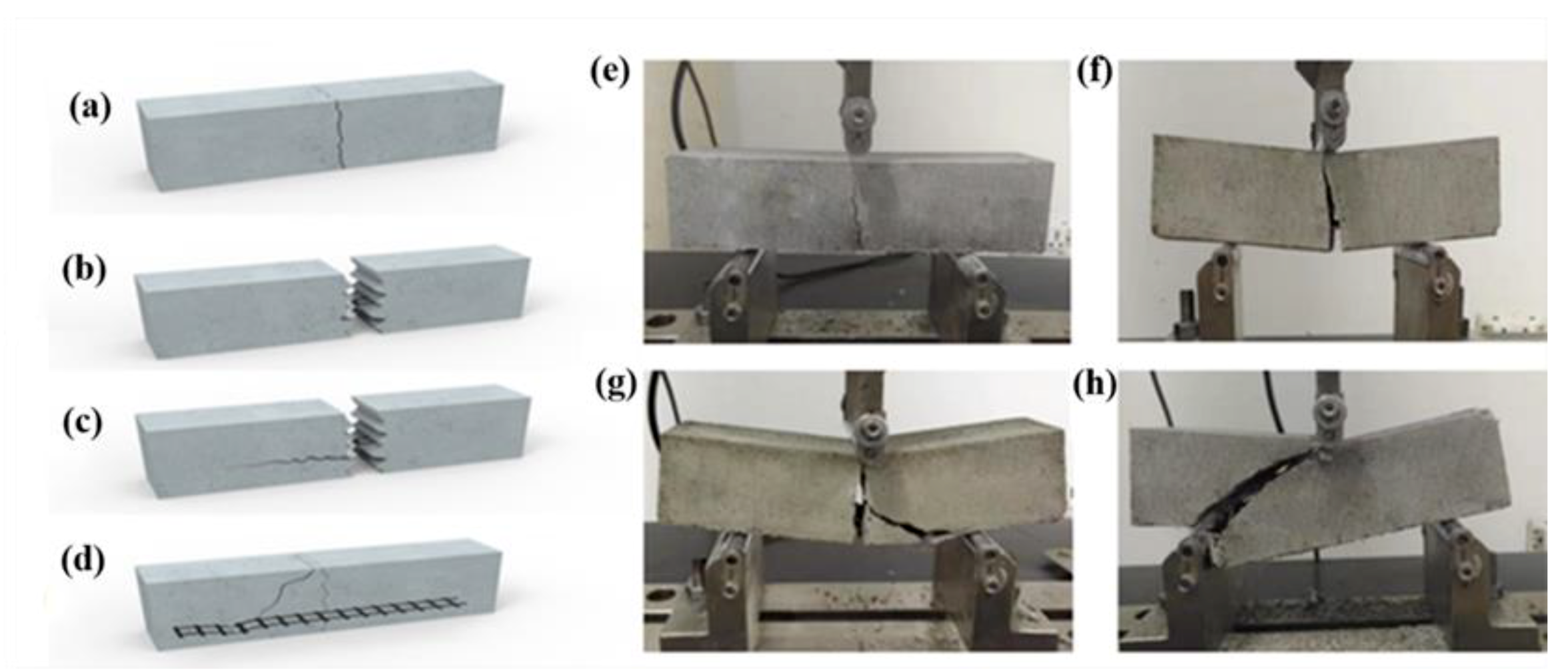
2.2.3. Preparation of the Three-Point Bending Test Specimens
2.3. Performance Testing and Characterization
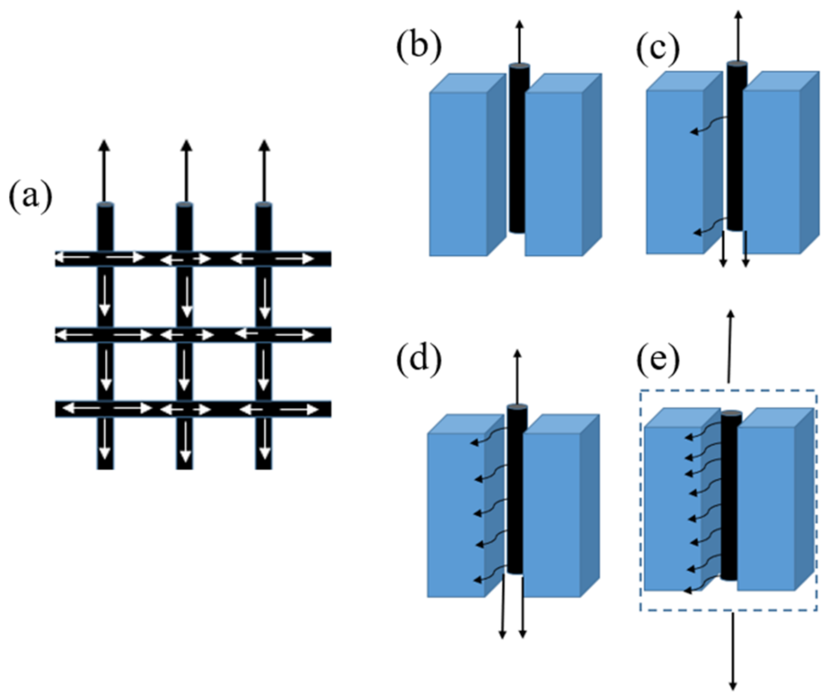
2.3.1. Double Shear Tests
2.3.2. Three-Point Bending Test
2.3.3. Scanning Electron Microscopy Analysis
2.3.4. X-Ray Photoelectron Spectroscopy Analysis
3. Results and Discussion
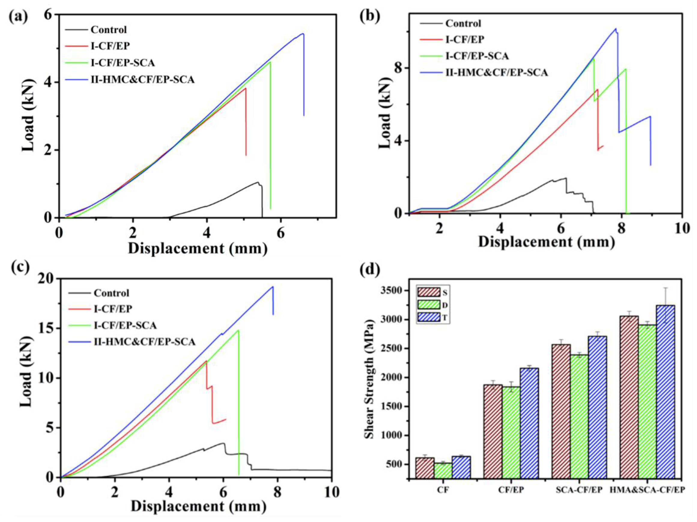
3.1. Double Shear Tests
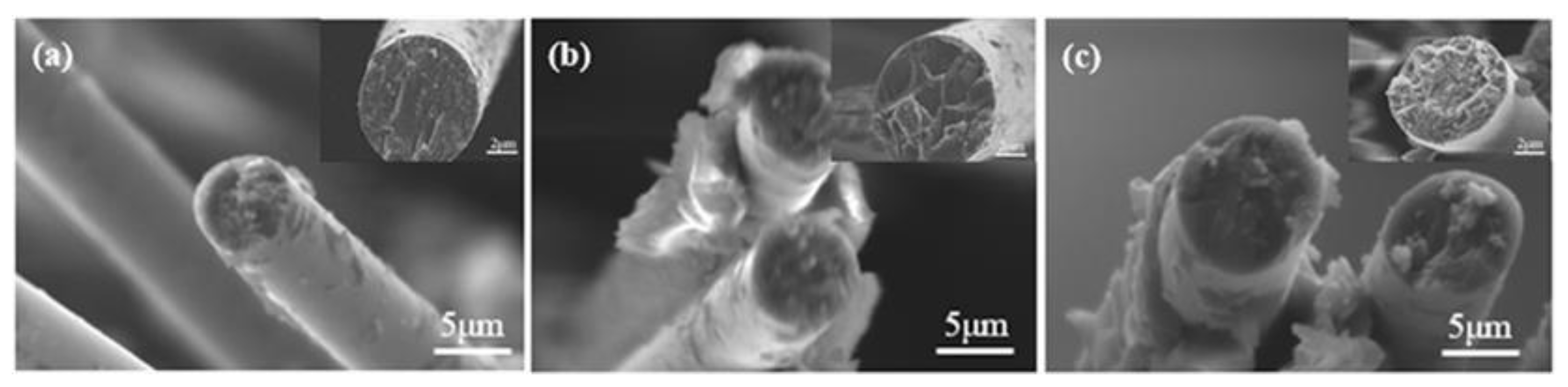
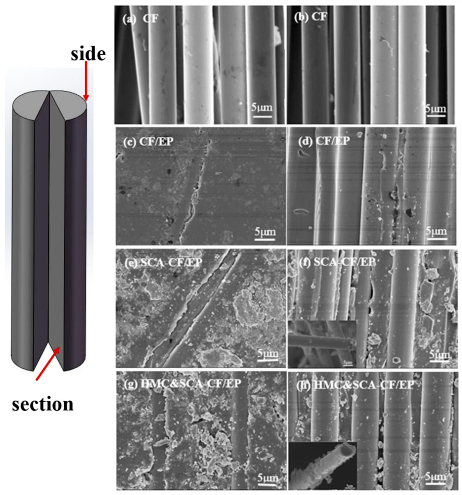
3.2. Scanning Electron Microscope (SEM) Tasks
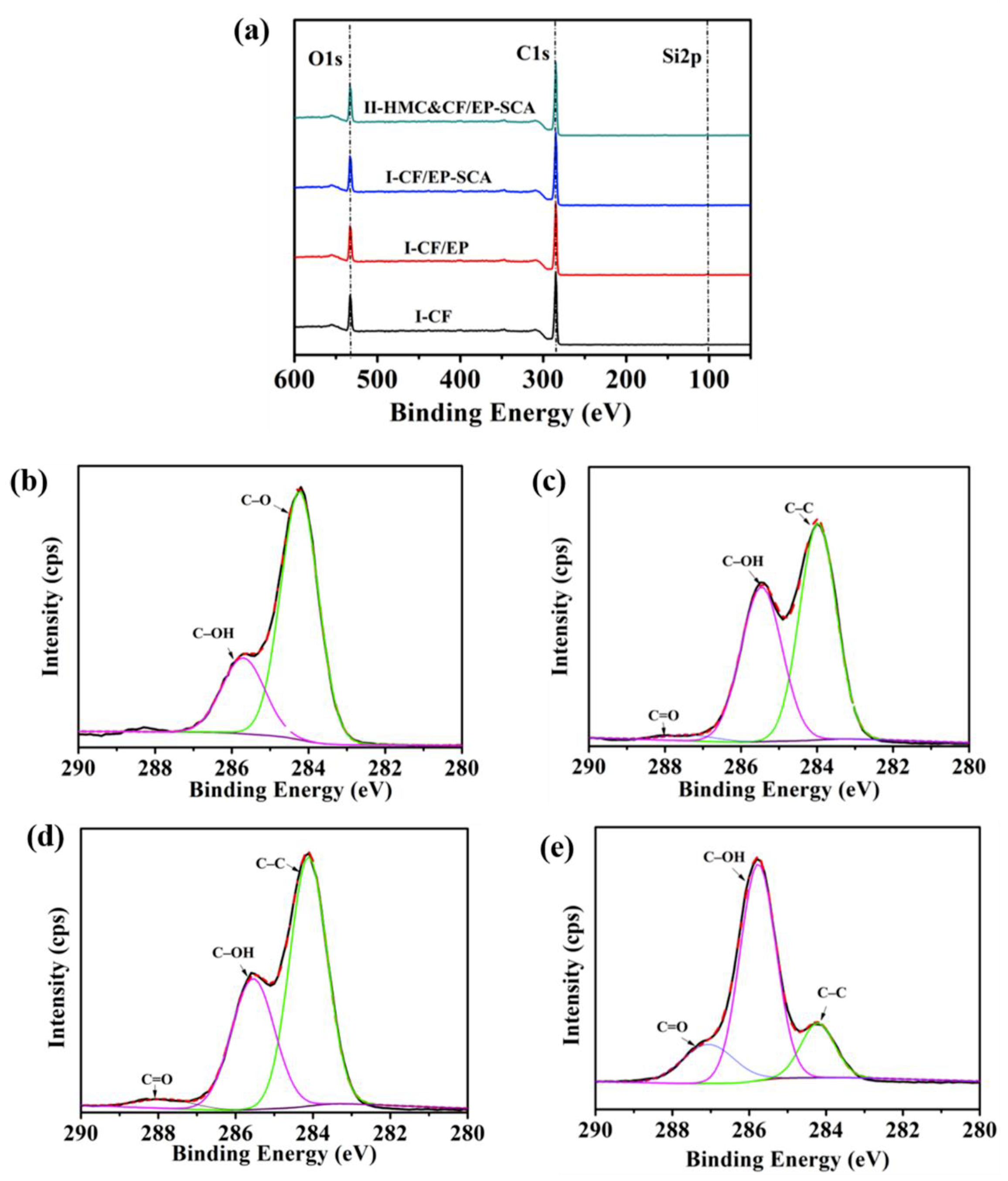
3.3. X-Ray Photoelectron Spectroscopy Analysis
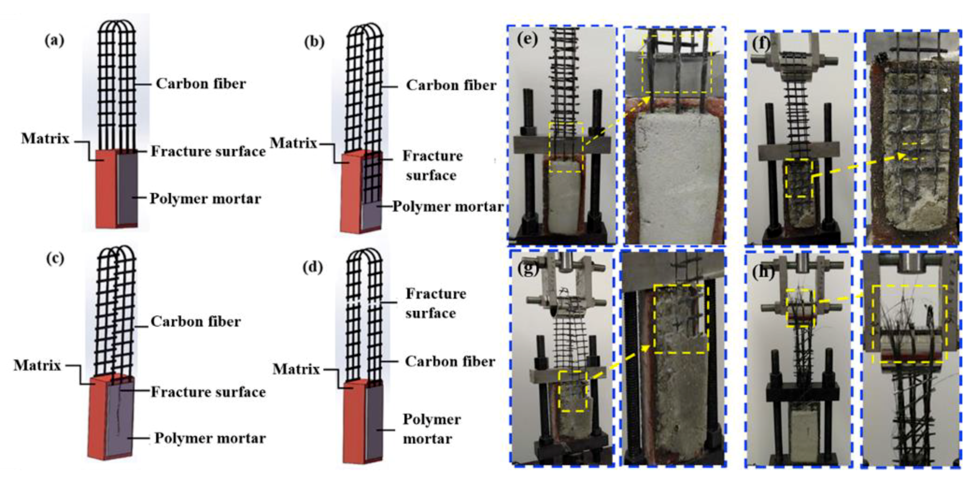
3.4. Failure Analysis
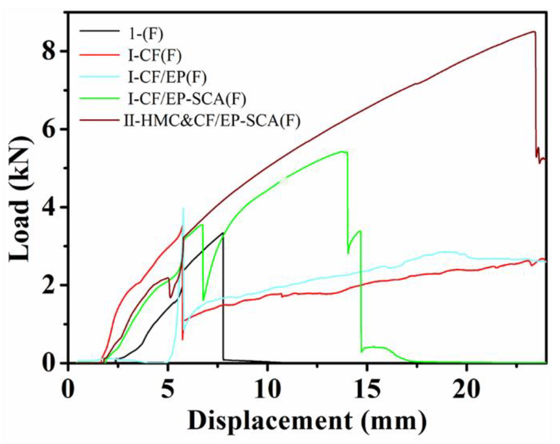
3.5. Three-Point Bending Test Results
3.6. Load-Transfer Model Analysis
4. Conclusions
Author Contributions
Funding
Acknowledgments
Conflicts of Interest
References
- Maddaloni, G.; Di Ludovico, M.; Balsamo, A.; Maddaloni, G.; Prota, A. Dynamic assessment of innovative retrofit techniques for masonry buildings. Compos. Part B Eng. 2018, 147, 147–161. [Google Scholar] [CrossRef]
- Wang, X.; Lam, C.C.; Iu, V.P. Comparison of different types of TRM composites for strengthening masonry panels. Constr. Build. Mater. 2019, 219, 184–194. [Google Scholar] [CrossRef]
- Theofanis, K.D. Experimental study on carbon fiber textile reinforced mortar system as a means for confinement of masonry columns. Constr. Build. Mater. 2019, 208, 723–733. [Google Scholar]
- Li, W.-Q.; Zhu, J.-H.; Chen, P.-Y.; Xing, F.; Li, D.; Su, M. Evaluation of carbon fiber reinforced cementitious matrix as a recyclable strengthening material. J. Clean Prod. 2019, 217, 234–243. [Google Scholar] [CrossRef]
- Li, J.Q.; Ma, H.Y.; Huang, Y.D. A method for characterizes the interface between carbon fiber and epoxy resin: Three-parameters exponential pattern. Mater. Chem. Phys. 2005, 89, 367–372. [Google Scholar] [CrossRef]
- Manocha, L.M. Role of fibre surface-matrix combination in carbon fiber reinforced epoxy composites. J. Mater. Sci. 1982, 17, 3039–3044. [Google Scholar] [CrossRef]
- Ombres, L. Analysis of the bond between fabric reinforced cementitious mortar (FRCM) strengthening systems and concrete. Compos. Part B Eng. 2015, 69, 418–426. [Google Scholar] [CrossRef]
- Peled, A.; Bentur, A. Fabric structure and its reinforcing efficiency in textile reinforced cement composites. Compos. Part A Appl. S 2003, 34, 107–118. [Google Scholar] [CrossRef]
- Carozzi, F.G.; Poggi, C. Mechanical properties and debonding strength of fabric reinforced cementitious matrix (FRCM) systems for masonry strengthening. Compos. Part B Eng. 2015, 70, 215–230. [Google Scholar] [CrossRef]
- Veedu, V.P.; Cao, A.; Li, X.; Ma, K.; Soldano, C.; Kar, S.; Ajayan, P.M.; Ghasemi-Nejhad, M.N. Multifunctional composites using reinforced laminae with carbon-nanotube forests. Nat. Mater. 2006, 5, 457–462. [Google Scholar] [CrossRef]
- Giebel, E.; Herrmann, T.; Simon, F.; Fery, A.; Buchmeiser, M.R. Surface modification of carbon fibers by free radical graft-polymerization of 2-Hydroxyethyl methacrylate for high mechanical strength fiber-matrix composites. Macromol Mater. Eng. 2017, 302, 1700210. [Google Scholar] [CrossRef]
- Donnini, J.; Corinaldesi, V.; Nanni, A. Mechanical properties of FRCM using carbon fabrics with different coating treatments. Compos. Part B Eng. 2016, 88, 220–228. [Google Scholar] [CrossRef]
- Karsli, N.G.; Aytac, A. Tensile and thermomechanical properties of short carbon fiber reinforced polyamide 6 composites. Compos. Part B Eng. 2013, 51, 270–275. [Google Scholar] [CrossRef]
- Devalve, C.; Pitchumani, R.J.C. Experimental investigation of the damping enhancement in fiber-reinforced composites with carbon nanotubes. Carbon 2013, 63, 71–83. [Google Scholar] [CrossRef]
- Yan, D.; Zhang, H.; Lu, S.; Yang, L.; Zhao, X.; He, F. Synergistic modification effect of polyvinylidene fluoride and polydopamine on mechanical and damping properties of three-dimensional braided carbon fibers reinforced composites. J. Mater. Sci. 2019, 54, 5457–5471. [Google Scholar] [CrossRef]
- Bowman, S.; Jiang, Q.; Memon, H.; Qiu, Y.; Liu, W.; Wei, Y. Effects of styrene-acrylic sizing on the mechanical properties of carbon fiber thermoplastic towpregs and their composites. Molecules 2018, 23, 547. [Google Scholar] [CrossRef] [PubMed]
- Chen, L.; Wu, L.W.; Jiang, Q.; Tian, D.; Zhong, Z.; Wang, Y.; Fu, H.J. Improving interlaminar fracture toughness and impact performance of carbon fiber/epoxy laminated composite by using thermoplastic fibers. Molecules 2019, 24, 3367. [Google Scholar] [CrossRef]
- Yuan, X.; Zhu, B.; Cai, X.; Qiao, K.; Zhao, S.; Yu, J. Influence of different surface treatments on the interfacial adhesion of graphene oxide/carbon fiber/epoxy composites. Appl. Surf. Sci. 2018, 458, 996–1005. [Google Scholar] [CrossRef]
- Stewart, A.; Schlosser, B.; Douglas, E.P. Surface Modification of Cured Cement Pastes by Silane Coupling Agents. ACS Appl. Mater. Inter. 2013, 5, 1218–1225. [Google Scholar] [CrossRef]
- Shuai, C.; Shuai, C.; Feng, P.; Yang, Y.; Xu, Y.; Qin, T.; Yang, S.; Gao, C.; Peng, S. Silane modified diopside for improved interfacial adhesion and bioactivity of composite scaffolds. Molecules 2017, 22, 511. [Google Scholar] [CrossRef]
- Yin, S.; Xu, S.; Li, H. Improved mechanical properties of textile reinforced concrete thin plate. J. Wuhan Univ. Technol. 2013, 28, 92–98. [Google Scholar] [CrossRef]
- Silva, F.d.A.; Butler, M.; Hempel, S.; Toledo Filho, R.D.; Mechtcherine, V. Effects of elevated temperatures on the interface properties of carbon textile-reinforced concrete. Cement. Concrete. Comp. 2014, 48, 26–34. [Google Scholar] [CrossRef]
- Yang, J.; Xiao, J.; Zeng, J.; Bian, L.; Peng, C.Y.; Yang, F.B. Matrix modification with silane coupling agent for carbon fiber reinforced epoxy composites. Fiber. Polym. 2013, 14, 759–766. [Google Scholar] [CrossRef]
- Rajan, R.; Rainosalo, E.; Thomas, S.P.; Ramamoorthy, S.K.; Zavasnik, J.; Vuorinen, J.; Skrifvars, M. Modification of epoxy resin by silane-coupling agent to improve tensile properties of viscose fabric composites. Polymer Bulletin 2018, 75, 167–195. [Google Scholar] [CrossRef]
- Kaynak, C.; Orgun, O.; Tincer, T. Matrix and interface modification of short carbon fiber-reinforced epoxy. Polym. Test. 2005, 24, 455–462. [Google Scholar] [CrossRef]
- Tayeb, A.H.; Amini, E.; Ghasemi, S.; Tajvidi, M. Cellulose nanomaterials-binding properties and applications: A review. Molecules 2018, 23, 2684. [Google Scholar] [CrossRef]
- Cheng, X.W.; Khorami, M.; Shi, Y.; Liu, K.Q.; Guo, X.Y.; Austin, S.; Saidani, M. A new approach to improve mechanical properties and durability of low-density oil well cement composite reinforced by cellulose fibres in microstructural scale. Constr. Build. Mater. 2018, 177, 499–510. [Google Scholar] [CrossRef]
- Parveen, S.; Rana, S.; Fangueiro, R.; Paiva, M.C. A novel approach of developing micro crystalline cellulose reinforced cementitious composites with enhanced microstructure and mechanical performance. Cement. Concrete. Comp. 2017, 78, 146–161. [Google Scholar] [CrossRef]
- Arkadiusz, K.; Piotr, K.; Łukasz, H.; Marcin, T.; Marek, S. Flexible Adhesive in Composite-to-Brick Strengthening—Experimental and Numerical Study. Polymer 2018, 10, 356. [Google Scholar]
- Wang, P.; Yang, J.; Liu, W.; Tang, X.-Z.; Zhao, K.; Lu, X.; Xu, S. Tunable crack propagation behavior in carbon fiber reinforced plastic laminates with polydopamine and graphene oxide treated fibers. Mater. Design 2017, 113, 68–75. [Google Scholar] [CrossRef]
- Naya, F.; Gonzalez, C.; Lopes, C.S.; Van der Veen, S.; Pons, F. Computational micromechanics of the transverse and shear behavior of unidirectional fiber reinforced polymers including environmental effects. Compos. Part A Appl. S 2017, 92, 146–157. [Google Scholar] [CrossRef]
- Zhou, H.W.; Mishnaevsky, L., Jr.; Yi, H.Y.; Liu, Y.Q.; Hu, X.; Warrier, A.; Dai, G.M. Carbon fiber/carbon nanotube reinforced hierarchical composites: Effect of CNT distribution on shearing strength. Compos. Part A Appl. S 2016, 88, 201–211. [Google Scholar] [CrossRef]
- Zheng, N.; He, J.; Zhao, D.; Huang, Y.; Gao, J.; Mai, Y.-W. Improvement of atomic oxygen erosion resistance of carbon fiber and carbon fiber/epoxy composite interface with a silane coupling agent. Mater. Design 2016, 109, 171–178. [Google Scholar] [CrossRef]
- Kwiecien, A.; Krajewski, P.; Hojdys, L.; Tekieli, M.; Slonski, M. Flexible adhesive in composite-to-brick strengthening-experimental and numerical study. Polymers 2018, 10, 356. [Google Scholar] [CrossRef] [PubMed]
Sample Availability: Samples of the carbon fiber mesh and mortar are available from the authors. |


| Material/Mechanical Property | Value |
|---|---|
| CF1 | |
| Ultimate breaking load | 3200 N |
| Design tensile strength | 101.2 MPa |
| Elastic modulus | 230 kN/mm2 |
| Areal density (force direction) | 80 g/m2 |
| Space | 2 mm |
| CWSM1 | |
| Compressive strength (28 Days) | 55 MPa |
| Flexural strength | 12 MPa |
| Splitting tensile bond strength | 7 MPa |
| Density | 2.05 g/cm3 |
| Clay Brick2 | |
| Compressive strength | 19.8 N/mm2 |
| Flexural strength | 3.66 N/mm2 |
| Splitting tensile strength | 2.46 N/mm2 |
| Young’s modulus | 5760 N/mm2 |
| SCA1 | |
| Density | 1.06 g/cm3 |
| Refractive index | 1.43 nD25 |
| Content | 98.4% |
| HMC1 | |
| Viscosity | 100,000 |
| Type of Composite | Specimen | |||||
|---|---|---|---|---|---|---|
| S-1 | 0.98 | 1.09 | ||||
| S-2 | 1.07 | |||||
| I-CF | S-3 | 1.23 | 8.3 | 690 | 0.19 | |
| S-4 | 1.11 | |||||
| S-5 | 1.05 | |||||
| D-1 | 1.93 | |||||
| D-2 | 1.92 | |||||
| I-CF | D-3 | 1.92 | 1.85 | 5.2 | 543 | 0.15 |
| D-4 | 1.79 | |||||
| D-5 | 1.71 | |||||
| T-1 | 3.44 | |||||
| T-2 | 3.31 | |||||
| I-CF | T-3 | 3.26 | 3.40 | 3.4 | 665 | 0.18 |
| T-4 | 3.55 | |||||
| T-5 | 3.45 | |||||
| S-1 | 3.72 | |||||
| S-2 | 3.31 | |||||
| I-CF/EP | S-3 | 3.54 | 3.53 | 4.2 | 2095 | 0.58 |
| S-4 | 3.55 | |||||
| S-5 | 3.53 | |||||
| D-1 | 6.31 | |||||
| D-2 | 6.27 | |||||
| I-CF/EP | D-3 | 6.36 | 6.53 | 4.7 | 1943 | 0.54 |
| D-4 | 6.83 | |||||
| D-5 | 6.91 | |||||
| T-1 | 11.22 | |||||
| T-2 | 11.52 | |||||
| I-CF/EP | T-3 | 11.73 | 11.51 | 2.2 | 2209 | 0.61 |
| T-4 | 11.31 | |||||
| T-5 | 11.78 | |||||
| S-1 | 4.42 | |||||
| S-2 | 4.39 | |||||
| I-CF/EP-SCA | S-3 | 4.74 | 4.56 | 3.4 | 2667 | 0.74 |
| S-4 | 4.67 | |||||
| S-5 | 4.60 | |||||
| D-1 | 8.52 | |||||
| D-2 | 8.25 | |||||
| I-CF/EP-SCA | D-3 | 8.67 | 8.50 | 1.8 | 2437 | 0.68 |
| D-4 | 8.52 | |||||
| D-5 | 8.52 | |||||
| T-1 | 14.80 | |||||
| T-2 | 14.13 | |||||
| I-CF/EP-SCA | T-3 | 14.08 | 14.46 | 2.8 | 2809 | 0.78 |
| T-4 | 14.99 | |||||
| T-5 | 14.29 | |||||
| S-1 | 5.24 | |||||
| S-2 | 5.66 | |||||
| II-HMC& | S-3 | 5.47 | 5.47 | 2.0 | 3185 | 0.88 |
| CF/EP-SCA | S-4 | 5.37 | ||||
| S-5 | 5.44 | |||||
| D-1 | 10.08 | |||||
| D-2 | 10.17 | |||||
| II-HMC& | D-3 | 10.55 | 10.33 | 2.0 | 2968 | 0.82 |
| CF/EP-SCA | D-4 | 10.54 | ||||
| D-5 | 10.33 | |||||
| T-1 | 15.62 | |||||
| T-2 | 15.65 | |||||
| II-HMC& | T-3 | 17.80 | 17.30 | 9.3 | 3602 | 1.00 |
| CF/EP-SCA | T-4 | 18.25 | ||||
| T-5 | 19.21 |
| Samples | Atomic Composition (atm.%) | ||
|---|---|---|---|
| Carbon | Oxygen | Silicon | |
| I-CF | 85.63 | 14.37 | - |
| I-CF/EP | 83.09 | 16.91 | - |
| I-CF/EP-SCA | 81.23 | 17.03 | 1.74 |
| II-HMC&CF/EP-SCA | 68.62 | 31.05 | 0.33 |
| Type of Composite | Specimen | |||||
|---|---|---|---|---|---|---|
| 1 | 3.28 | 3.24 | ||||
| 2 | 3.34 | |||||
| I-(F) | 3 | 3.34 | 4.2 | 7.60 | 0.63 | |
| 4 | 3.21 | |||||
| 5 | 3.01 | |||||
| 1 | 3.53 | |||||
| 2 | 3.63 | |||||
| I-CF(F) | 3 | 3.52 | 3.53 | 1.8 | 8.28 | 0.69 |
| 4 | 3.47 | |||||
| 5 | 3.48 | |||||
| 1 | 3.90 | |||||
| 2 | 3.91 | |||||
| I-CF/EP(F) | 3 | 3.98 | 3.91 | 1.0 | 9.18 | 0.7 |
| 4 | 3.87 | |||||
| 5 | 3.91 | |||||
| 1 | 5.43 | |||||
| I-CF/EP-SCA(F) | 2 | 5.43 | ||||
| 3 | 5.43 | 5.35 | 2.5 | 12.52 | 1.04 | |
| 4 | 5.34 | |||||
| 5 | 5.12 | |||||
| 1 | 8.12 | |||||
| 2 | 7.93 | |||||
| II-HMC&CF/EP-SCA(F) | 3 | 8.06 | 8.09 | 2.4 | 18.82 | 1.57 |
| 4 | 7.95 | |||||
| 5 | 8.42 |
© 2019 by the authors. Licensee MDPI, Basel, Switzerland. This article is an open access article distributed under the terms and conditions of the Creative Commons Attribution (CC BY) license (http://creativecommons.org/licenses/by/4.0/).
Share and Cite
Wu, B.; Xu, X.; Luo, S.; Yan, D.; Song, K.; Zhang, X.; He, F. Study on the Mechanical Properties and Strengthening Mechanism of Interface-Modified Carbon Fiber Mesh Reinforced Cement-Based Composites with SCA&HMC. Molecules 2019, 24, 3989. https://doi.org/10.3390/molecules24213989
Wu B, Xu X, Luo S, Yan D, Song K, Zhang X, He F. Study on the Mechanical Properties and Strengthening Mechanism of Interface-Modified Carbon Fiber Mesh Reinforced Cement-Based Composites with SCA&HMC. Molecules. 2019; 24(21):3989. https://doi.org/10.3390/molecules24213989
Chicago/Turabian StyleWu, Bo, Xiaohai Xu, Shigang Luo, Dedao Yan, Kai Song, Xiang Zhang, and Fang He. 2019. "Study on the Mechanical Properties and Strengthening Mechanism of Interface-Modified Carbon Fiber Mesh Reinforced Cement-Based Composites with SCA&HMC" Molecules 24, no. 21: 3989. https://doi.org/10.3390/molecules24213989