Article

Windowed Joint Detection and Decoding with IR-HARQ for Asynchronous SCMA Systems

1
The State Key Laboratory of Integrated Services Networks, Xidian University, Xi’an 710071, China
2
Science and Technology on Communication Networks Laboratory, Shijiazhuang 050081, China
*
Author to whom correspondence should be addressed.
Entropy 2023, 25(6), 930; https://doi.org/10.3390/e25060930
Submission received: 9 May 2023 / Revised: 31 May 2023 / Accepted: 8 June 2023 / Published: 13 June 2023
(This article belongs to the Special Issue Coding and Entropy)

Abstract

:
To improve the decoding performance of asynchronous sparse code multiple access (SCMA) systems over additive white Gaussian noise (AWGN) channels, this paper proposes a novel windowed joint detection and decoding algorithm for a rate-compatible (RC), LDPC code-based, incremental redundancy (IR) hybrid automatic repeat quest (HARQ) scheme. Since incremental decoding can exchange information iteratively with the detections made at previous consecutive time units, we propose a windowed joint detection and decoding algorithm. The extrinsic information exchanging process is performed between the decoders and the previous w detectors at different consecutive time units. Simulation results show that the sliding-window IR-HARQ scheme for the SCMA system outperforms the original IR-HARQ scheme with a joint detection and decoding algorithm. The throughput of the SCMA system with the proposed IR-HARQ scheme is also improved.

1. Introduction

In the field of next-generation communication systems for crowded scenarios, Non-Orthogonal Multiple Access (NOMA) technologies have emerged as promising solutions that meet access requirements with high reliability, low latency, and low costs. There are several available non-orthogonal access technologies, including power-domain non-orthogonal multiple access (PD-NOMA) [1], interleave division multiple access (IDMA) [2,3], multi-user shared access (MUSA) [4], pattern division multiple access (PDMA) [5], and sparse code multiple access (SCMA) [6]. These technologies allow multiple users to send messages simultaneously in the same frequency and code domains while maintaining orthogonality in other fields such as power allocation, interleavers, and patterns. SCMA is an advanced version of a low-density signature (LDS) that uses sparse code to modulate data symbols. SCMA systems use multi-dimensional constellation (MDS) mapping with a sparse indicator matrix, unlike LDS spreading and quadrature amplitude modulation (QAM). The receiver uses a decoder that employs a message-passing algorithm (MPA)-based multi-user detection (MUD). SCMA systems have better error-correction performance than LDS systems, with an overloading factor of up to 150 %  [6].

1.1. Related Work and Motivation of SCMA

Research on SCMA systems has primarily focused on codebook design [7,8,9,10], low-complexity detection [11,12,13], and iterative processing between detection and decoding. Mahmoud et al. proposed a unified framework for multiuser codebook designs in [7], which was later expanded upon in [8,9,10] with various design methods that offer better performance and lower complexity. For example, Zhang et al. introduced a codebook based on a uniquely decomposable constellation group (UDCG) in [8], while Munich et al. investigated the design of unequal error protection (UEP) codebooks in [9] and Bao et al. focused on codebook design for SCMA systems over Rayleigh fading channels in [10]. To simplify the decoder complexity, threshold-based MPA was introduced in [11], while [12] proposed a low-complexity decoding algorithm based on list sphere decoding. More recently, a novel algorithm based on alternating maximization with the exact penalty was proposed in [14] for the minimum Euclidean distance (MED) maximization problem. Zheng et al. proposed a simplified SCMA codebook with a separable structure in [15], which simplifies MED maximization when implementing a low-complexity detector. Based on the mother codebook, Lei et al. proposed a novel codebook design scheme to achieve better error performance and further explored an improved unified optimization to maximize the MED of each user in [16].

1.2. Related Work to SCMA Systems with HARQ Schemes

The SCMA system has seen an increase in usage and research, but few studies have examined its performance with the hybrid automatic repeat quest (HARQ) scheme. Shiomitsu et al. demonstrated the efficiency of this scheme in improving decoder performance for fifth-generation mobile communication technology (5G) transmission strategies in [17]. Building on this idea, the authors in [18] explore an SCMA-oriented HARQ scheme that enhances the reliability of new information by retransmitting correctly decoded codewords. However, this scheme may not be suitable for random access scenarios, as it requires immediate retransmission by users experiencing transmission failure in the current slot. To address this issue, ref. [19] presents an improved HARQ scheme dedicated to SCMA under grant-free random access scenarios. However, these two schemes have drawbacks, such as wasting resources and limited use of fixed-rate codes, which restricts the use of Chase combining (CC) HARQ for the SCMA system. Since the IR-HARQ scheme is a promising alternative to the CC-HARQ scheme for SCMA systems to improve throughput, Zhu et al. showed that the combination of rate-compatible (RC) codes and an IR-HARQ scheme performs well in [20,21]. Moreover, the binary RC-LDPC codes have been accepted as standard codes for the enhanced mobile broadband (eMBB) data channel of 5G communication in [22]. Thus, it is worth studying the performance of the RC-LDPC code-based IR-HARQ scheme for SCMA systems.

1.3. Main Contribution

This paper focuses on exploring the performance of an RC-LDPC code-based IR-HARQ scheme for SCMA systems. In [23], Zhu et al. explain the fundamental principle of this scheme and present a joint detection and decoding algorithm. However, the incremental decoder utilized in their work is solely related to the detection in the current transmission round, and not across different rounds. Consequently, there is room for optimization of the decoding algorithm’s efficiency and accuracy. To address this, we propose the transmission mechanism of the asynchronous IR-HARQ scheme, in which information can be sent during different transmission rounds based on each user’s channel conditions. This approach enables the incremental decoders and MUD to consider not only the extrinsic information at the current time unit but also at previous time units. Moreover, the windowed joint detection and decoding algorithm to simulate this scenario is introduced. The simulation indicates that the proposed scheme can enhance the bit error ratio (BER) performance and achieve better throughput over a wide range of SNRs.
The novelty and contributions of this paper can be summarized as follows:
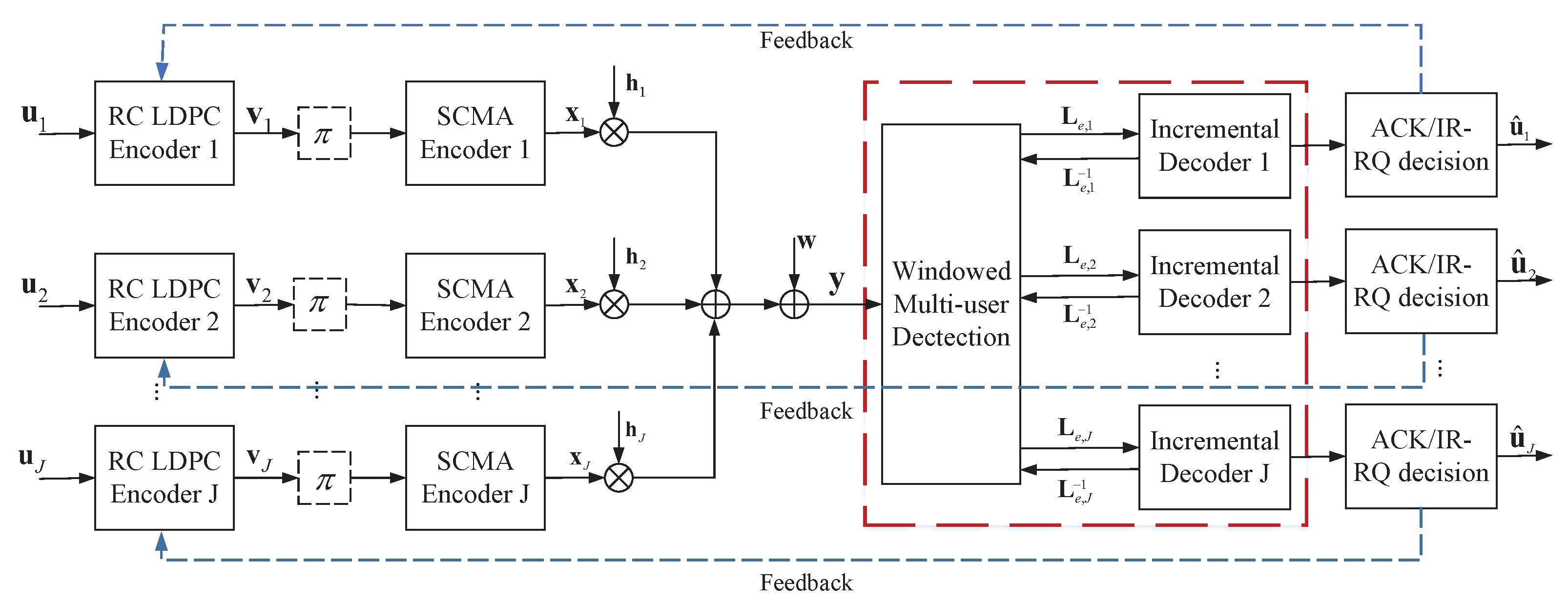
  • We build an asynchronous uplink SCMA system with the RC-LDPC code-based IR-HARQ scheme and present the transmission mechanism of the asynchronous IR-HARQ scheme.
  • We propose a novel windowed joint detection and decoding algorithm with IR-HARQ for asynchronous SCMA systems.

1.4. Paper Organization

The rest of the paper is structured as follows. Section 2 briefly reviews the RC-LDPC codes, based on Kite codes, and introduces the proposed SCMA system model with the IR-HARQ scheme. Section 3 introduces the asynchronous IR-HARQ scheme, and then the RC-LDPC code-based IR-HARQ schemes for SCMA systems are detailed. The simulation results are presented in Section 4, and the conclusion is summarized in Section 5.

2. System Model

2.1. RC-LDPC Codes Based on Kite Codes

Kite codes, refs. [24,25] designed for noisy channels, are represented by C [ , k ; p ] . These codes are defined by their k dimension and a p-sequence p = p 1 , p 2 , , p t , , where 1 < p t < 1 for t 0 . A codeword c = ( u , v ) C [ , k ; p ] consists of an information vector u = u 1 , u 2 , , u k 1 and a parity sequence v = v 1 , v 2 , , v t , .
The prefix Kite code with length n can be represented as C [ n , k ] and is a systematic linear code with r b = n × k parity bits. Its parity-check matrix H can be expressed as
H = ( H u , H v ) ,
where H u, corresponding to information bits, is a binary matrix of size r × k and H v, corresponding to parity bits, is a dual-diagonal matrix of size r × r . It can be seen that H u is a random-like binary matrix whose entries are governed by the p-sequence p :
Hv = 1 1 1 1 1 1 1 r × r .
Therefore, a Kite code is a unique LDPC code with a degree distribution determined by the p-sequence. We can use the sum-product algorithm during decoding. The construction of Kite codes allows for the generation of specific parity-check bits corresponding to each coding rate, with the higher-rate codes being able to serve as prefix codes of lower-rate codes. From Kite codes, RC-LDPC codes can be obtained, but in order to ensure that all prefix codes are good enough, the optimization of p i , which determines the degree distribution of Kite code, is necessary.
Zhang et al. partitioned coding rates from 0.05 to 1 into 19 intervals in their work [25], assuming p t to be a step function of the coding rates. They enforced p t = q l whenever t satisfied the coding rate k / ( t + k ) ( 0.05 l , 0.05 ( l + 1 ) ] , utilizing 19 possible different values q l , 1 l 19 . Therefore, the optimization process can be simplified to selecting q = q 1 , q 2 , , q 19 for use in the greedy optimization algorithm. As q l represents a check-node degree distribution varying with coding rates, the RC-LDPC codes based on Kite codes (RC Kite codes) perform well after optimization. Zhang et al. also provided an optimization algorithm in [25] that achieved the approximate right-regular distribution.

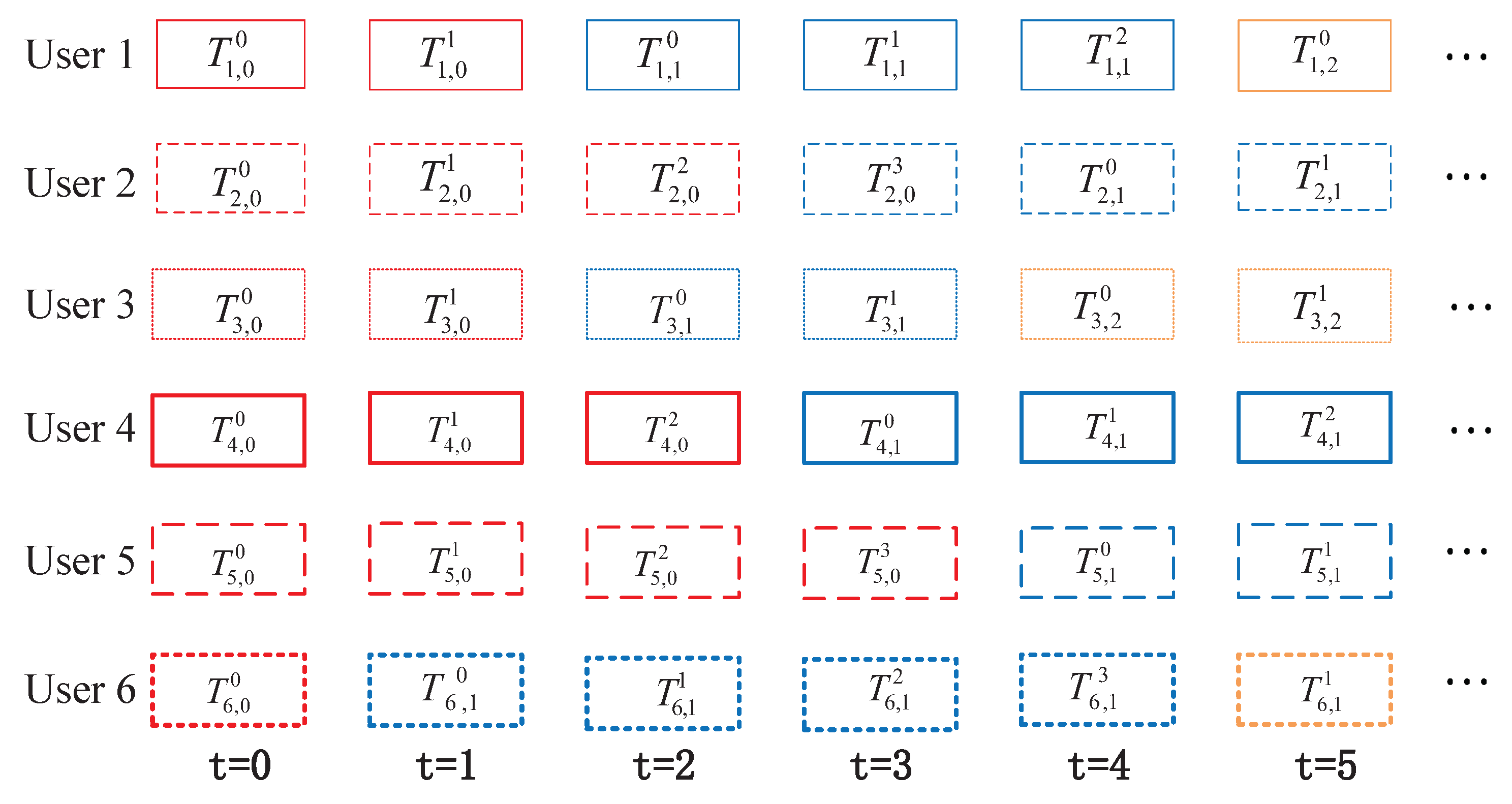
2.2. Asynchronous IR-HARQ SCMA

We can consider an uplink SCMA system with L physical resources and each physical resource denoted by U i , where i 1 , 2 , , L . After mapping, it becomes a codeword x i of the SCMA codebooks. If we let h i represent the channel vector from the base station to the i-th physical resource, the received signal y can be expressed as
y = E s L i = 1 L diag ( h i ) x i + n .
The diagram in Figure 1 illustrates the IR-HARQ strategy employed by the asynchronous uplink SCMA system with J users and L physical resources. Each user j, j 1 , 2 , , J , encodes a data sequence u j of length k using an RC-LDPC code independently. The result is a codeword v j = v j , 1 , v j , 2 , , v j , N with each v j , n being either 0 or 1. To simplify, we denote the vector ( v j , 1 , v j , 2 , , v j , N ) as { v j , t } t = 1 N . The windowed joint detection decoder, boxed in the red line, is utilized at the receiver. Moreover, extrinsic information exchange between J decoders and the windowed detector is shown.
This paper discusses an SCMA system that involves 6 users sharing 4 resource elements. Each user has a codebook of size M, denoted by X j = { a j ( i ) C L , 1 i M } . The codebook consists of sparse signal vectors a j ( i ) = { a j ( i ) [ ] } l = 1 L , where n non-zero entities are positioned based on a sparse indicator vector f j . The SCMA encoder is defined as v j = { v j , t } t = 1 N x j = { x j , t } t = 1 N with x j , t X j . The SCMA system uses an L × J indicator matrix F = [ f 1 , f 2 , , f J ] to assign the vector f j to user j. Each f j is a binary vector of length L with row and column weight of d f and n, respectively. Therefore, each user transmits a coded symbol using n = 2 complex symbols. The indicator matrix F is given as
F 4 × 6 = 0 1 1 0 1 0 1 0 1 0 0 1 0 1 0 1 0 1 1 0 0 1 1 0 .
To learn more about the SCMA encoder, please refer to [7,26].
Assuming that all users’ signals are perfectly synchronized, we can combine Equations (3) and (4). The received superposed signals at the receiver during the symbol duration t can be written as
y t = j = 1 J diag ( h j , t ) x j , t + w t ,
where h j , t is the channel gain vector and w t is the additive complex Gaussian noise vector. In addition, the correlation between each h j , t is determined by the coherence time of the channel, or Doppler spread. In situations with high mobility, the channel is rapidly time-varying and experiences multiple channel realizations in each retransmission round.
This paper considers that each transmitted block has a length of N 0 and that D max represents the maximum number of transmissions, including the initial transmission and retransmissions. For a user j, j 1 , 2 , , J , the retransmission request will be sent back to the sender if decoding fails. Upon receiving this request, the sender will send I redundancy bits specific to user j through the channel. This process will continue until decoding is successful or the maximum number of transmissions is reached.

3. Windowed Joint Detection and Decoding Algorithm

3.1. IR-HARQ Transmission Scheme

The detailed transmission mechanism of the asynchronous IR-HARQ scheme is shown in Figure 2. To begin, the first set of information symbols for each user is encoded using RC-LDPC codes, resulting in an initial block codeword sequence. If the receiver fails to decode this initial block, parity-check blocks related to it are sent over the channel and added to the initial block codeword to create a longer one. Without loss of generality, we assume that the block length for each transmission is the same under the IR-HARQ transmission scheme in 5G. The maximum number of transmissions for the initial block, including information symbols, is limited to four (i.e., D max = 4 ). For user j, j 1 , 2 , , J , the block T j , i d represents the dth transmission ( d D max ) of length N 0 related to its initial block i, including the information symbols.
At the start, each user sends their initial block with a length of N 0 and a code rate of R 0 = k / N 0 . The SCMA encoder processes six blocks simultaneously and sends the resulting sequence through the channel. At the receiver, a joint detection and decoding algorithm is used. If all users successfully decode their blocks, they receive a new initial block for the next time unit. If decoding fails for some users, they receive a block of redundant parity bits corresponding to the previous initial block. Users who successfully decode the block receive a new initial block at the next time unit. This process is repeated for subsequent time units. In the provided diagram, users 1–4 decode their initial blocks with fewer than four transmissions, allowing them to move on to the second initial block. However, user 5 fails to decode their block in four transmissions, so a new initial block is transmitted on the fifth round. Similarly, user 6 fails to decode the second initial block in four transmissions, leading to the transmission of the third initial block in the sixth round.

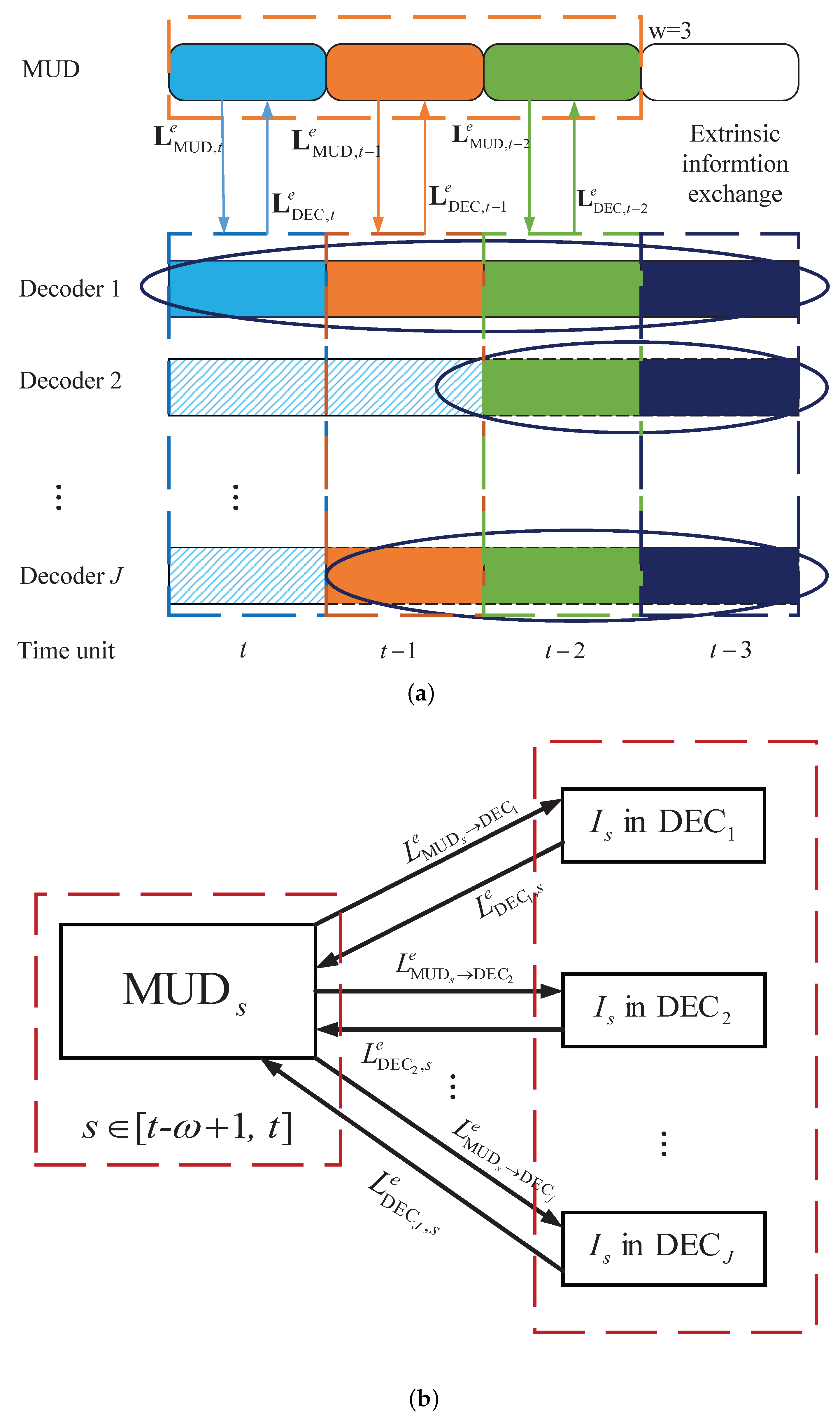
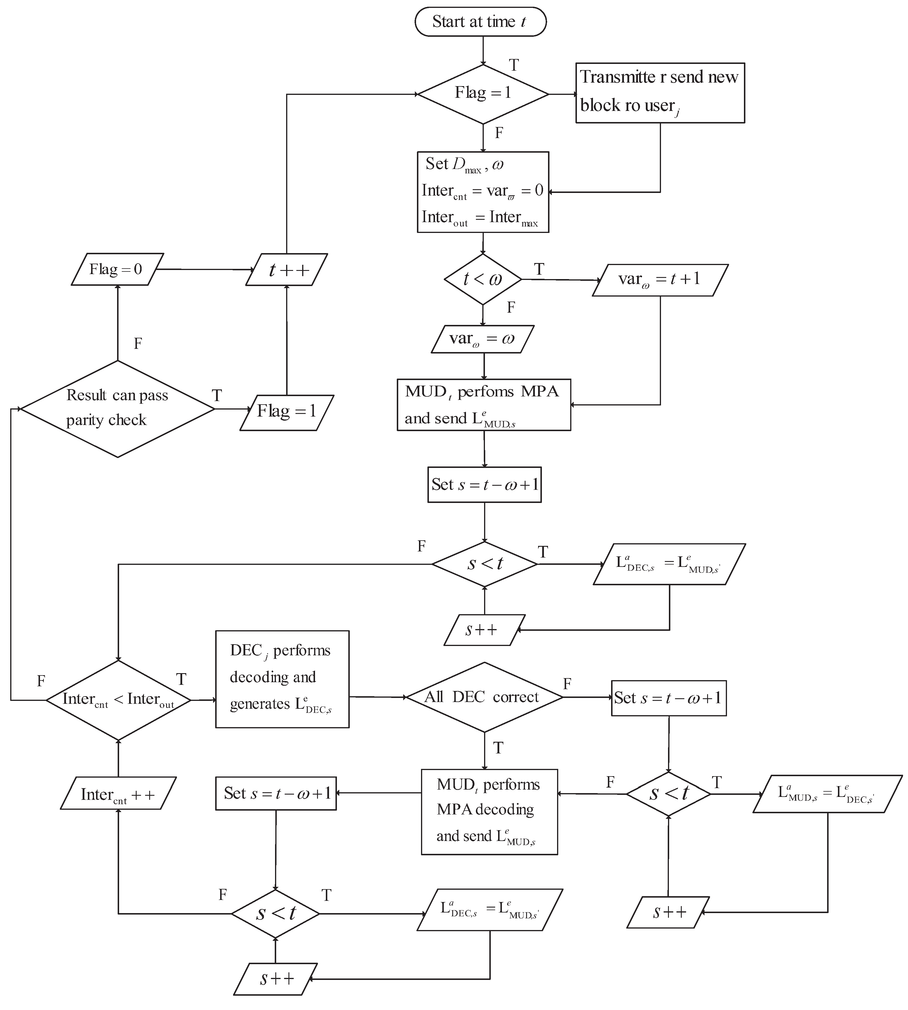
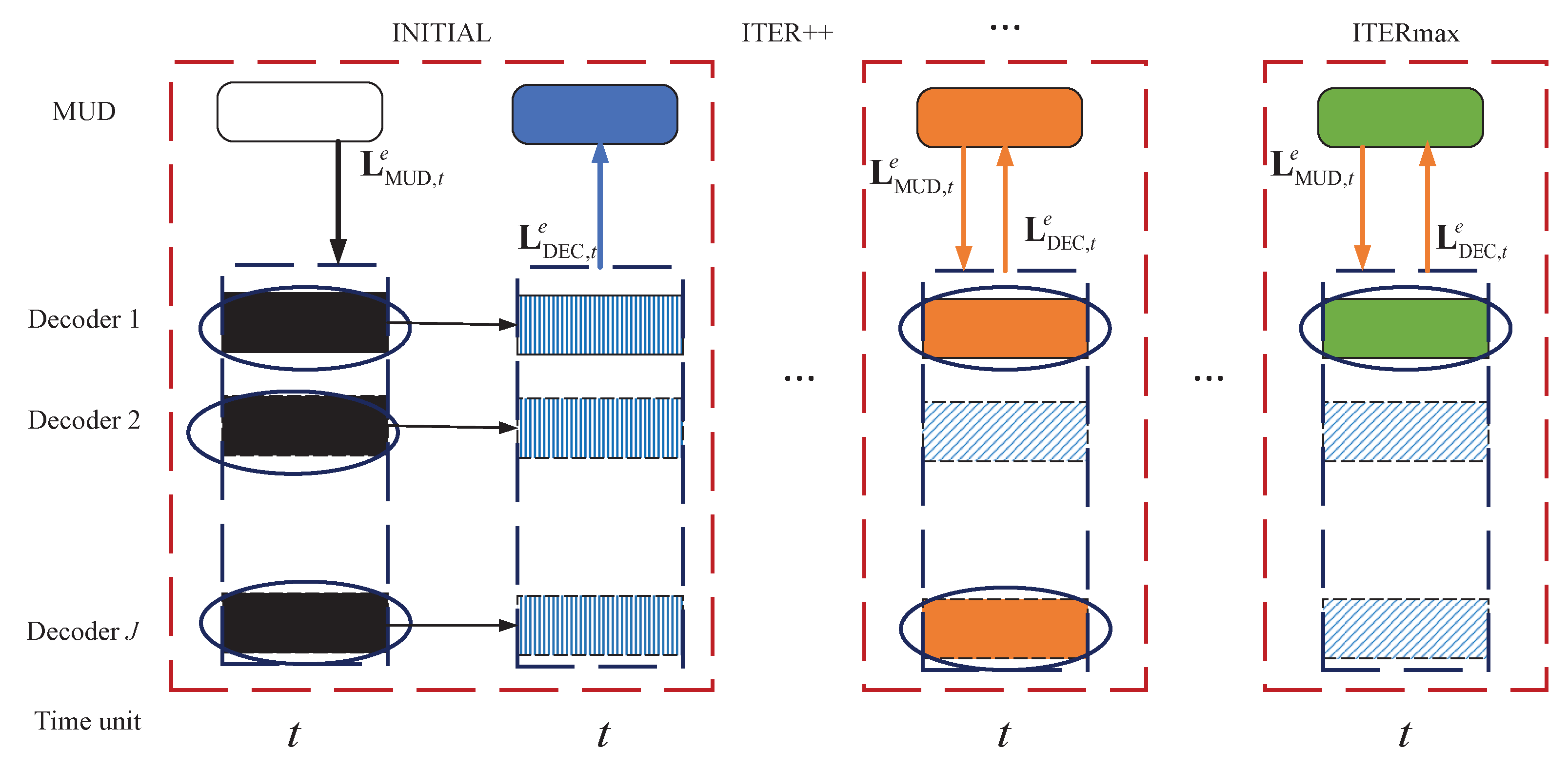
3.2. Windowed Joint Detection and Decoding Algorithm

As described in Section 3.1, the incremental decoders at a specific time unit t depend not only on the detector at that time unit but also on the detectors at previous time units. This is because redundant parity bits are transmitted at different time units. To ensure accuracy, it is necessary to have iterations between the decoder and detector at the same time unit, as well as joint iterations between the decoder at the current time unit and the detectors at the previous time units.
The decoding diagram of the windowed joint detection and decoding algorithm is shown in Figure 3. Assuming that the maximum number of transmissions for an information block is D max = 4 and the window size is w = 3 . For simplicity, each decoder is represented by DEC j , j = 1 , , J , and the block length received at a one-time unit is I. The slashed rectangles in the diagram depict the blocks that have been successfully decoded. The log-likelihood ratio (LLR) values of these decoded blocks remain constant during the iteration between the detector and decoder. The other colored rectangles represent the undecoded blocks. For example, and as shown in Figure 3, for DEC 1 , four blocks from time unit t to t 3 are decoded by an RC-LDPC decoder DEC 1 . The resulting extrinsic information L DEC 1 , t e , L DEC 1 , t 1 e , , L DEC 1 , t w + 1 e is transmitted to detectors MUD t , MUD t 1 ,…, MUD t w + 1 , respectively. Similarly, for DEC 2 , two blocks ( block t 2 , blcok t 3 ) are decoded by an RC-LDPC decoder DEC 2 . The extrinsic information L DEC 2 , t 2 e is transmitted to the MUD t 2 . (Because the current window size is 3, L DEC 2 , t 3 e will not be transmitted to MUD t 3 .) The sliding window joint detection and decoding algorithm works as follows.
When the channel information is received at time unit t, the MUD (referred to as MUD t ) performs the message-passing algorithm (MPA) detection and generates the extrinsic LLR information L MUD , t e . This information is then exchanged with the DECs.
After receiving the LLRs L MUD , t e from MUD t , the decoders DEC t , t = 1 , 2 , , J , perform the incremental decoding (step 2 in Figure 3a). (The length of different decoders in the DEC is different because some users decode more new information symbols due to their good channel conditions.) The extrinsic LLRs , L DEC e , w = L DEC , t e , L DEC , t 1 e , , L DEC , t w + 1 e , are generated and delivered to MUD i , i = t , t 1 , , t w + 1 as the a priori information written by
L MUD , s a = L DEC , s e , s = t , t 1 , , t w + 1 .
It is obvious that the window size is w D max . Then, w MUDs work separately and deliver the resulting extrinsic information L MUD e , w = L MUD , t e , L MUD , t 1 e , , L MUD , t w + 1 e to the DEC as
L DEC , s a = L MUD , s e , s = t , t 1 , , t w + 1 .
Upon receiving the extrinsic LLRs from MUD i , i = t , t 1 , , t w + 1 , the DEC performs incremental decoding and sends back the new extrinsic information to the w MUDs according to (6). This iteration process continues until the maximum number Iter out is achieved.
The detailed windowed joint detection and decoding algorithm is given in Algorithm 1. Additionally, the functionality of this scheme for the user j at time unit t during operation is illustrated in Figure 4.
In addition, if the window size is set to w = 1 , then the iteration process between MUD s ( MUD t , , MUD t w + 1 ) and DEC t reduces to the original joint detection and decoding algorithm discussed in this paper. We can see the details in Figure 5, where the slashed rectangles indicate successfully decoded blocks, and the vertically lined rectangles represent blocks that failed to be decoded. The traditional joint detection and decoding algorithm, as shown in Figure 5, performs the iterations between the decoder and detector at the same time unit. However, the windowed joint detection and decoding algorithm exchanges the information between the detector and decoder not only at the current time units but also at the previous w time units, resulting in a noticeable improvement in complexity. Although achieving performance improvement comes at the cost of complexity, it is a worthy trade-off for the decoding algorithm for the system with HARQ .
Algorithm 1 Windowed Joint Detection and decoding Algorithm.
1:
Initialization: D max = 4 , w = 3 , Iter out = 5 , Iter cnt = 0 , var w = 0 .
2:
if time unit t < w  then
3:
    var w = t + 1 .
4:
else
5:
    var w = w .
6:
end if
7:
MUD t performs the MPA multi-user detection and sends the extrinsic information to DEC t according to (7);
8:
while  Iter cnt   <   Iter out   do
9:
   for  j = 1 , 2 , , J  do
10:
     According to the current column and row indexes of the parity matrix, start the incremental decoding in DEC j :
11:
     if decoded correct then
12:
        Continue.
13:
     else
14:
        Save the extrinsic information;
15:
     end if
16:
   end for
17:
   if All the users decode correctly then
18:
     break;
19:
   else
20:
      DEC i sends the extrinsic information to the detector MUD i , i = t , t 1 , , t w + 1 according to (6);
21:
   end if
22:
    MUD t , , MUD t w + 1 carry on the MPA multi-user detection separately;
23:
   MUDs deliver the extrinsic LLRs to the DEC t according to (6).
24:
    Iter out + + ;
25:
end while
26:
for j = 1 , 2 , , J do
27:
   if decoded correct then
28:
     Send ACK to the transmitter ; hence, the new initial block will be sent.
29:
     Update current column and row indexes.
30:
   else
31:
     Update current column and row indexes.
32:
     Send NACK to the transmitter ; hence, the corresponding redundant parity bits will be sent.
33:
   end if
34:
end for

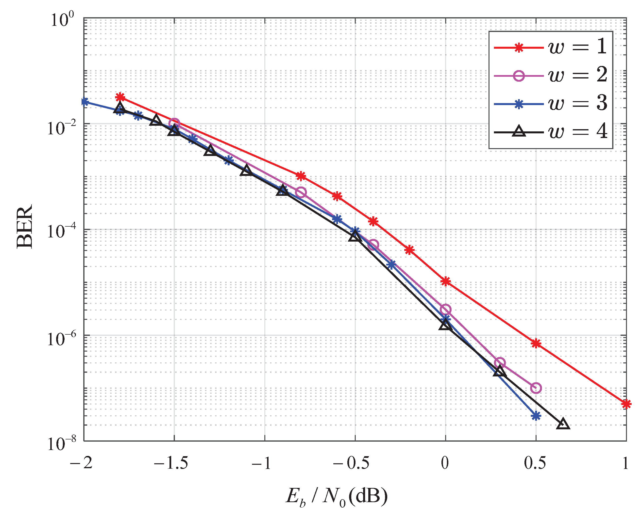
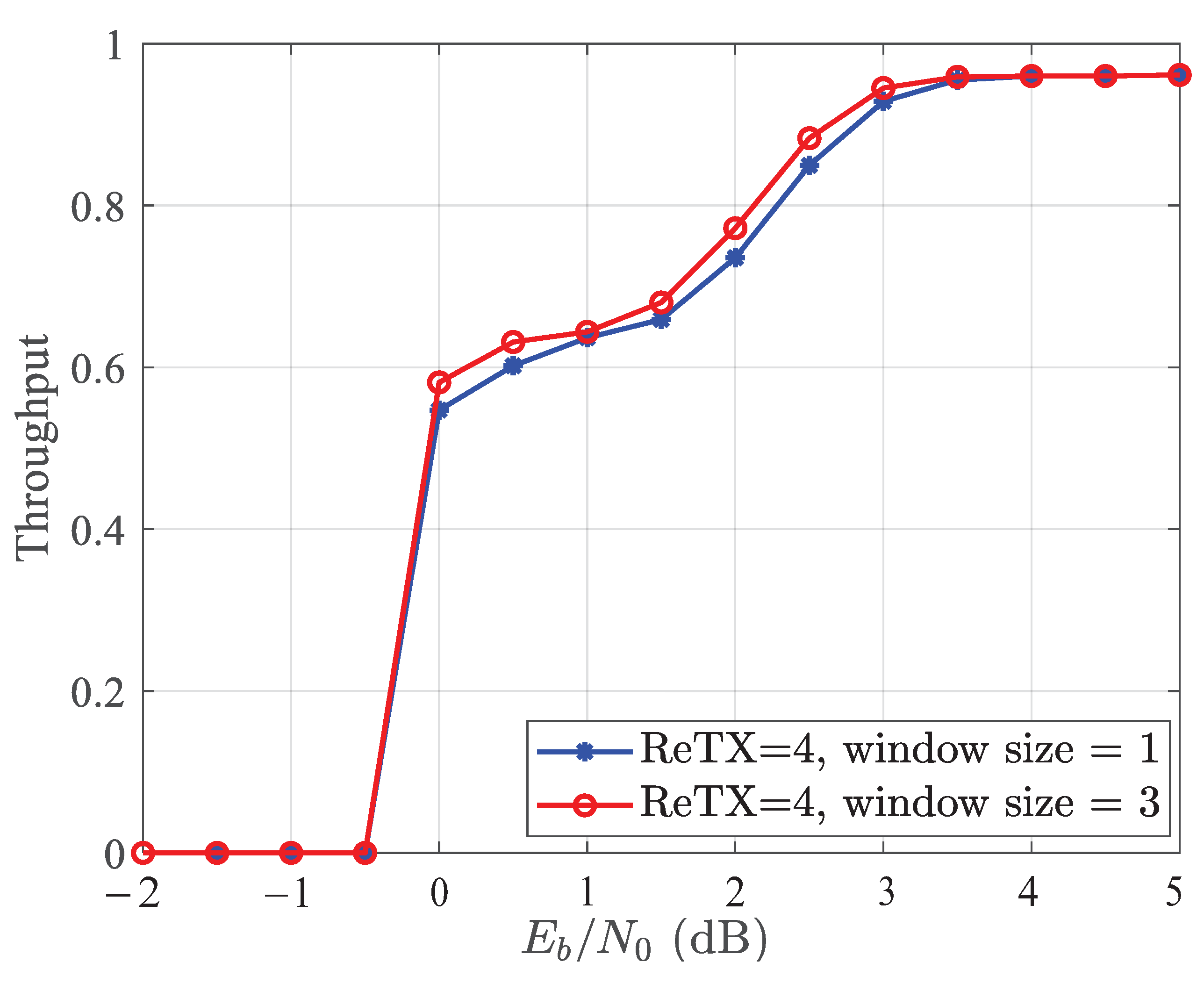
4. Simulation Results

To demonstrate the effectiveness of the proposed algorithm, we compare the performance of the original joint detection and decoding algorithm (According to Section 1.2, limited studies have been conducted on the decoding algorithm for the SCMA system with HARQ in recent years. Additionally, the innovative approaches presented in [18,19] are designed for the SCMA system with CC-HARQ, not the SCMA system with IR-HARQ), which can be obtained by setting the window size to w = 1 , with the performance of the proposed algorithm.
Considering the SCMA system with an RC-LDPC encoder, the information length is k = 256 , and the block length transmitted each time is I = 400 . Then, the initial block length and code rate are N 0 = 400 and R 0 = 0.64 . We assume that there are J = 6 users sharing L = 4 resource elements. The maximum number of transmissions for one information block is D max = 4 , and the window size changes from w = 1 to w = 4 .
Figure 6 shows the BER performance comparison of the SCMA system with two detection and decoding algorithms: traditional joint detection and decoding and windowed joint detection and decoding. The system uses a four-point, high-dimensional constellation over the additive white Gaussian noise (AWGN) channel, with an outer iteration of Iter out = 3 and an inner iteration of Iter in = 5 . It is shown in Figure 6 that with the increase in w, the BER performance of windowed joint detection and decoding algorithm improves. In addition, when w is large enough ( w = 3 here), the BER performance improves slightly with the increase in w. We also see that the SCMA system using the windowed joint detection and decoding algorithm with w = 3 outperforms the traditional joint detection and decoding algorithm, achieving about a 0.5 dB improvement in BER performance.
Figure 7 compares the throughput of the traditional joint detection and decoding algorithm and the windowed joint detection and decoding algorithm. The throughput is denoted as the actual rate of RC-LDPC codes used to decode the fixed information blocks correctly. At low SNRs, both performances approach zero, while at high enough SNRs, both are good. The comparison shows that the SCMA system with the proposed algorithm has better throughput.

5. Conclusions

This paper introduces a new transmission strategy for the SCMA system using an RC-LDPC code and IR-HARQ. Additionally, we propose a windowed joint detection and decoding algorithm. The simulation results demonstrate that this scheme outperforms the original joint detection and decoding algorithm by approximately 0.5 dB and achieves a higher throughput across a wide range of SNRs.

Author Contributions

Conceptualization, M.G. and M.Z.; methodology, M.G. and B.B.; software, M.G. and M.Z.; validation, M.G. and M.Z.; formal analysis, M.G. and M.Z.; investigation, M.G. and M.Z.; resources, M.G.; data curation, M.G. and M.Z.; writing—original draft preparation, M.G.; writing—review and editing, M.Z. and B.B.; visualization, M.Z. and B.B.; supervision, M.Z. and B.B.; project administration, M.G. and M.Z.; funding acquisition, M.Z. and B.B. All authors have read and agreed to the published version of the manuscript.

Funding

This work was supported in part by the National Key R&D Program of China under Grant 2021YFB2900500 and in part by the National Natural Science Foundation of China under Grants 62271380 and 62171356.

Data Availability Statement

No new data were created or analyzed in this study. Data sharing is not applicable to this article.

Conflicts of Interest

The authors declare no conflict of interest.

Abbreviations

The following abbreviations are used in this manuscript:
RCrate-compatible
IRincremental redundancy
SCMAsparse code multiple access
HARQhybrid automatic repeat quest
AWGNadditive white Gaussian noise
NOMAnon-orthogonal multiple access
PD-NOMApower-domain non-orthogonal multiple access
IDMAinterleave division multiple access
MUSAmulti-user shared access
PDMApattern division multiple access
LDSlow-density signature
QAMquadrature amplitude modulation
MPAmessage passing algorithm
UDCGuniquely decomposable constellation group
BERbit error ratio
UEPunequal error protection
MEDminimum Euclidean distance
5Gfifth-generation mobile communication technology
CCChase combining
eMBBenhanced mobile broadband
LLRlog-likelihood ratio
MUDmulti-user detection
MPAmessage-passing algorithm

References

  1. Saito, Y.; Kishiyama, Y.; Benjebbour, A.; Nakamura, T.; Li, A.; Higuchi, K. Non-orthogonal multiple access (NOMA) for cellular future radio access. In Proceedings of the 2013 IEEE 77th Vehicular Technology Conference (VTC Spring), Dresden, Germany, 2–5 June 2013; Volume 6, pp. 1–5. [Google Scholar]
  2. Li, P. Interleave-division multiple access and chip-by-chip iterative multi-user detection. IEEE Commun. Mag. 2005, 6, S19–S23. [Google Scholar]
  3. Li, P.; Liu, L.; Wu, K.Y.; Leung, W.K. Interleave-division multiple-access. IEEE Trans. Wirel. Commun. 2004, 4, 938–947. [Google Scholar]
  4. Yuan, Z.; Yu, G.; Li, W.; Yuan, Y.; Wang, X.; Xu, J. Multi-user shared access for Internet of Things. In Proceedings of the 2016 IEEE 83rd Vehicular Technology Conference: (VTC Spring), Nanjing, China, 15–18 May 2016; pp. 1–5. [Google Scholar]
  5. Zeng, J.; Li, B.; Su, X.; Rong, L.; Xing, R. Pattern division multiple access (PDMA) for cellular future radio access. In Proceedings of the Internet Conference on Wireless Communication & Signal Processing (WCSP); Nanjing, China: 15–18 October 2015; pp. 1–5.
  6. Nikopour, H.; Baligh, H. Sparse code multiple access. In Proceedings of the 2013 IEEE 24th Annual International Symposium on Personal, Indoor, and Mobile Radio Communications (PIMRC), London, UK, 8–11 September 2013; pp. 332–336. [Google Scholar]
  7. Mahmoud, T.; Hosein, N.; Alireza, B.; Hadi, B. SCMA codebook design. In Proceedings of the 2014 IEEE 80th Vehicular Technology Conference: (VTC Fall), Vancouver, BC, Canada, 14–17 September 2014; pp. 1–5. [Google Scholar]
  8. Zhang, X.; Zhang, D.; Yang, L.; Han, G.; Chen, H.-H.; Zhang, D. SCMA codebook design based on uniquely decomposable constellation groups. IEEE Trans. Wirel. Commun. 2021, 8, 4828–4842. [Google Scholar] [CrossRef]
  9. Mheich, Z.; Wen, L.; Xiao, P.; Maaref, A. Unequal error protection SCMA codebooks. IEEE Trans. Veh. Technol. 2019, 4, 4055–4058. [Google Scholar] [CrossRef]
  10. Bao, J.; Ma, Z.; Ding, Z.; Karagiannidis, G.K.; Zhu, Z. On the design of multiuser codebooks for uplink SCMA systems. IEEE Commun. Lett. 2016, 10, 1920–1923. [Google Scholar] [CrossRef] [Green Version]
  11. Yang, L.; Liu, Y.; Siu, Y. Low complexity message passing algorithm for SCMA system. IEEE Commun. Lett. 2016, 12, 2466–2469. [Google Scholar] [CrossRef]
  12. Wei, F.; Chen, W. Low complexity iterative receiver design for sparse code multiple access. IEEE Trans. Commun. 2017, 2, 621–634. [Google Scholar] [CrossRef] [Green Version]
  13. Tang, S.; Hao, L.; Ma, Z. Low complexity joint MPA detection for downlink MIMO-SCMA. In Proceedings of the IEEE Global Communications Conference: (GLOBECOM), Washington, DC, USA, 4–8 December 2016; pp. 1–4. [Google Scholar]
  14. Huang, C.; Su, B.; Lin, T.; Huang, Y. Downlink SCMA codebook design with low error rate by maximizing minimum Euclidean distance of superimposed codewords. IEEE Trans. Veh. Technol. 2022, 5, 5231–5245. [Google Scholar] [CrossRef]
  15. Zheng, Y.; Xin, J.; Wang, H.; Zhang, S.; Qiao, Y. A low-complexity codebook design scheme for SCMA systems over an AWGN channel. IEEE Trans. Veh. Technol. 2022, 8, 8675–8688. [Google Scholar] [CrossRef]
  16. Lei, T.; Ni, S.; Cheng, N.; Chen, S.; Song, X. A novel scheme for the construction of the SCMA codebook. IEEE Access 2022, 10, 100987–100998. [Google Scholar] [CrossRef]
  17. Shiomitsu, Y.; Okamoto, E.; Mikami, M.; Yoshino, H. Poster: Effective frame configuration of 5G URLLC using open-loop HARQ for autonomous driving. In Proceedings of the IEEE Vehicular Networking Conference: (VNC), Los Angeles, CA, USA, 4–6 December 2019; pp. 1–2. [Google Scholar]
  18. Long, Y.; Chen, Z.; Guo, Z.; Fang, J. A novel HARQ scheme for SCMA systems. IEEE Wirel. Commun. Lett. 2016, 5, 452–455. [Google Scholar] [CrossRef]
  19. Lian, J.; Zhou, S.; Zhang, X.; Wang, Y. An improved HARQ scheme for SCMA under random access. In Proceedings of the 2017 3rd IEEE International Conference on Computer and Communications (ICCC), Chengdu, China, 13–16 December 2017; pp. 1163–1167. [Google Scholar]
  20. Zhu, M.; Bai, B.; Dou, J.; Ma, X. Kite code-based incremental redundancy hybrid ARQ scheme for fast-fading channels. Chin. Sci. Bull. 2014, 35, 5029–5041. [Google Scholar] [CrossRef]
  21. Zhu, M.; Qu, Y.; Zhang, K.; Bai, B.; Ma, X. An improved ensemble of variable-rate LDPC codes with precoding. In Proceedings of the IEEE International Symposium on Information Theory:(ISIT), Honolulu, HI, USA, 29 June–4 July 2014; pp. 2177–2181. [Google Scholar]
  22. 3GPP TSG RAN WG1 Meeting #87; RAN1 Chairman’s Notes: Reno, NV, USA, 2016.
  23. Zhu, M.; He, Q.; Zhang, R.; Bai, B. Rateless coding based incremental redundancy HARQ scheme for SCMA systems. Mob. Netw. Appl. 2018, 8, 1028–1034. [Google Scholar] [CrossRef]
  24. Zhu, M.; Wei, Y.; Bai, B.; Ma, X. Nonbinary Kite codes: A family of nonbinary rate-compatible LDPC codes. In Proceedings of the IEEE International Symposium on Information Theory: (ISIT), Hong Kong, China, 14–19 June 2015; pp. 1094–1098. [Google Scholar]
  25. Zhang, K.; Ma, X.; Zhao, S.; Bai, B.; Zhang, X. A new ensemble of rate-compatible LDPC codes. In Proceedings of the IEEE International Symposium on Information Theory: (ISIT), Cambridge, MA, USA, 14–19 June 2012; pp. 2536–2540. [Google Scholar]
  26. Chen, Y.-M.; Chen, J.-W. On the design of near-optimal sparse code multiple access codebooks. IEEE Trans. Commun. 2020, 5, 2950–2962. [Google Scholar] [CrossRef]
Figure 1. Block diagram of an asynchronous uplink SCMA system with the RC-LDPC code-based IR-HARQ scheme.
Entropy 25 00930 g001
Figure 2. Transmission mechanism of asynchronous SCMA-oriented IR-HARQ scheme.
Entropy 25 00930 g002
Figure 3. Decoding diagram with the windowed joint detection and decoding algorithm. (a) Windowed joint detection and decoding algorithm at different time units with w = 3. (b) The extrinsic information exchanged between MUD s , s [ t w + 1 , t ] and DEC j , j = 1 , , J at time unit s.
Entropy 25 00930 g003
Figure 4. The procession of the jth user decoding at the time unit t.
Entropy 25 00930 g004
Figure 5. Decoding diagram with the original joint detection and decoding algorithm.
Entropy 25 00930 g005
Figure 6. BER performance of the SCMA system with the IR-HARQ scheme using the windowed joint detection and decoding algorithm with D max = 4 .
Entropy 25 00930 g006
Figure 7. Throughput of the SCMA system with the IR-HARQ scheme using the windowed joint detection and decoding algorithm with D max = 4 .
Entropy 25 00930 g007
Disclaimer/Publisher’s Note: The statements, opinions and data contained in all publications are solely those of the individual author(s) and contributor(s) and not of MDPI and/or the editor(s). MDPI and/or the editor(s) disclaim responsibility for any injury to people or property resulting from any ideas, methods, instructions or products referred to in the content.

