Analysis of Controlled Rabi Flopping in a Double Rephasing Photon Echo Scheme for Quantum Memories


Abstract
:1. Introduction
2. Theory
3. Discussion
3.1. DR Photon Echoes
3.1.1. D-Pulse
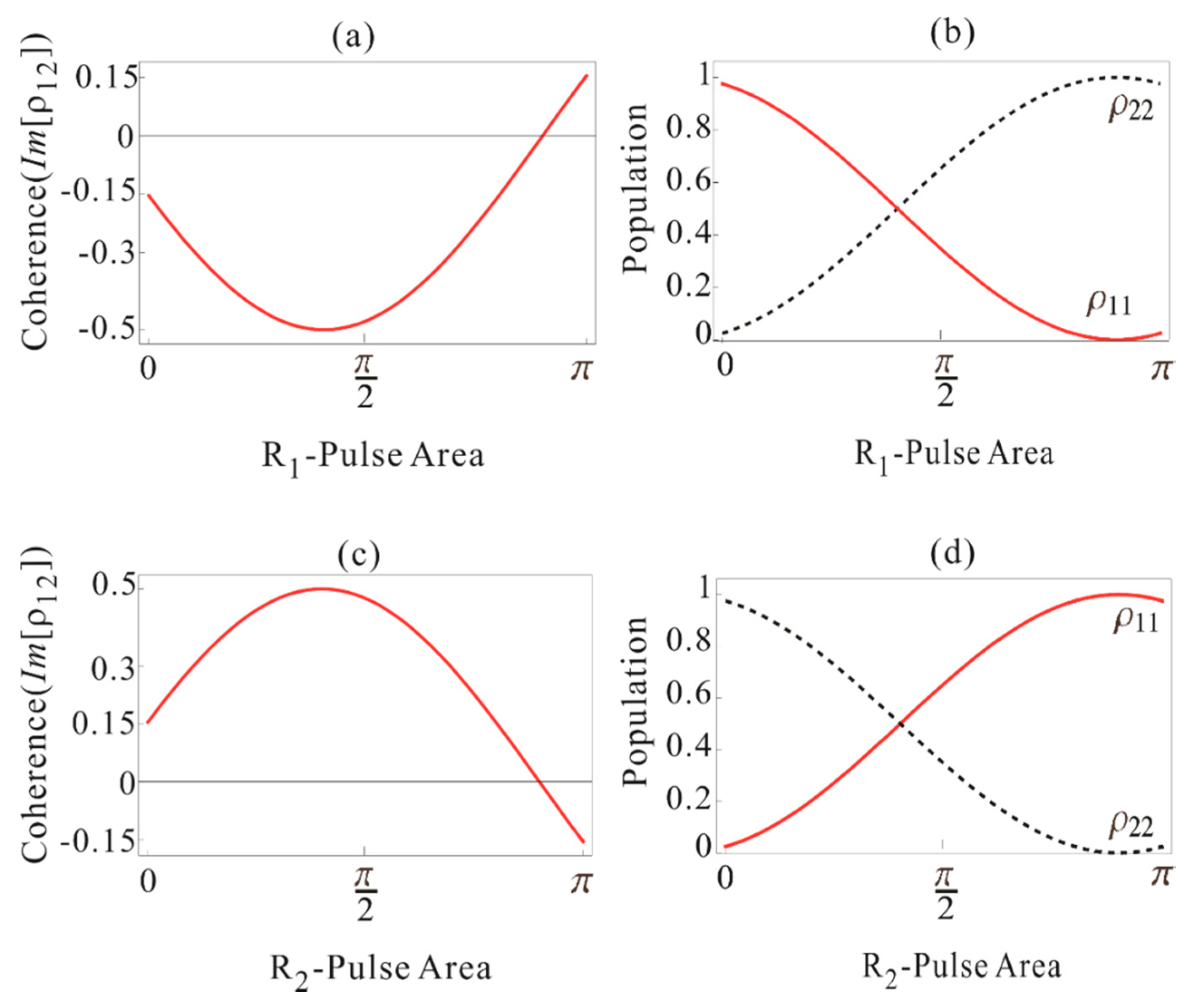
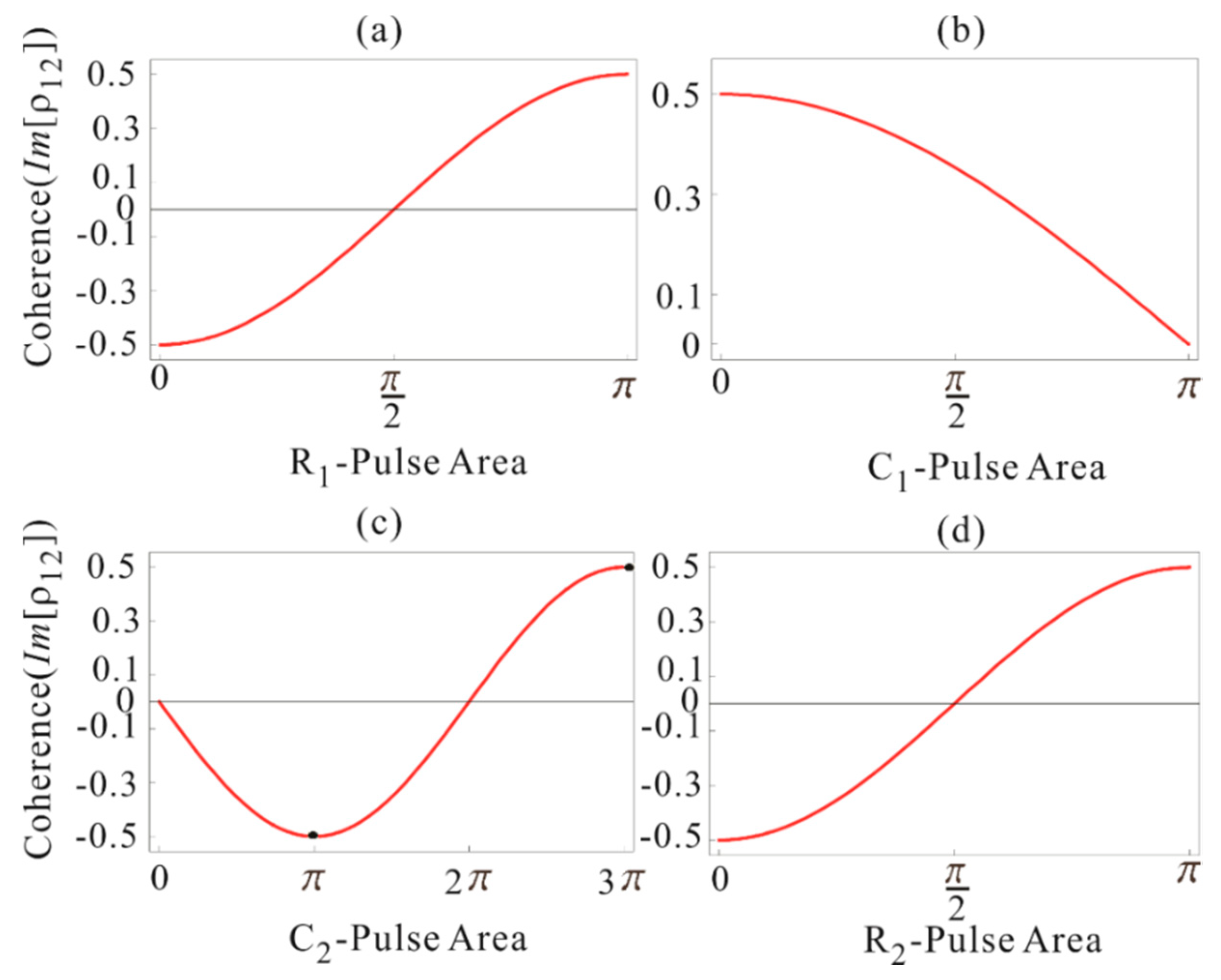
3.1.2. R1-Pulse
3.2. CDR Photon Echoes
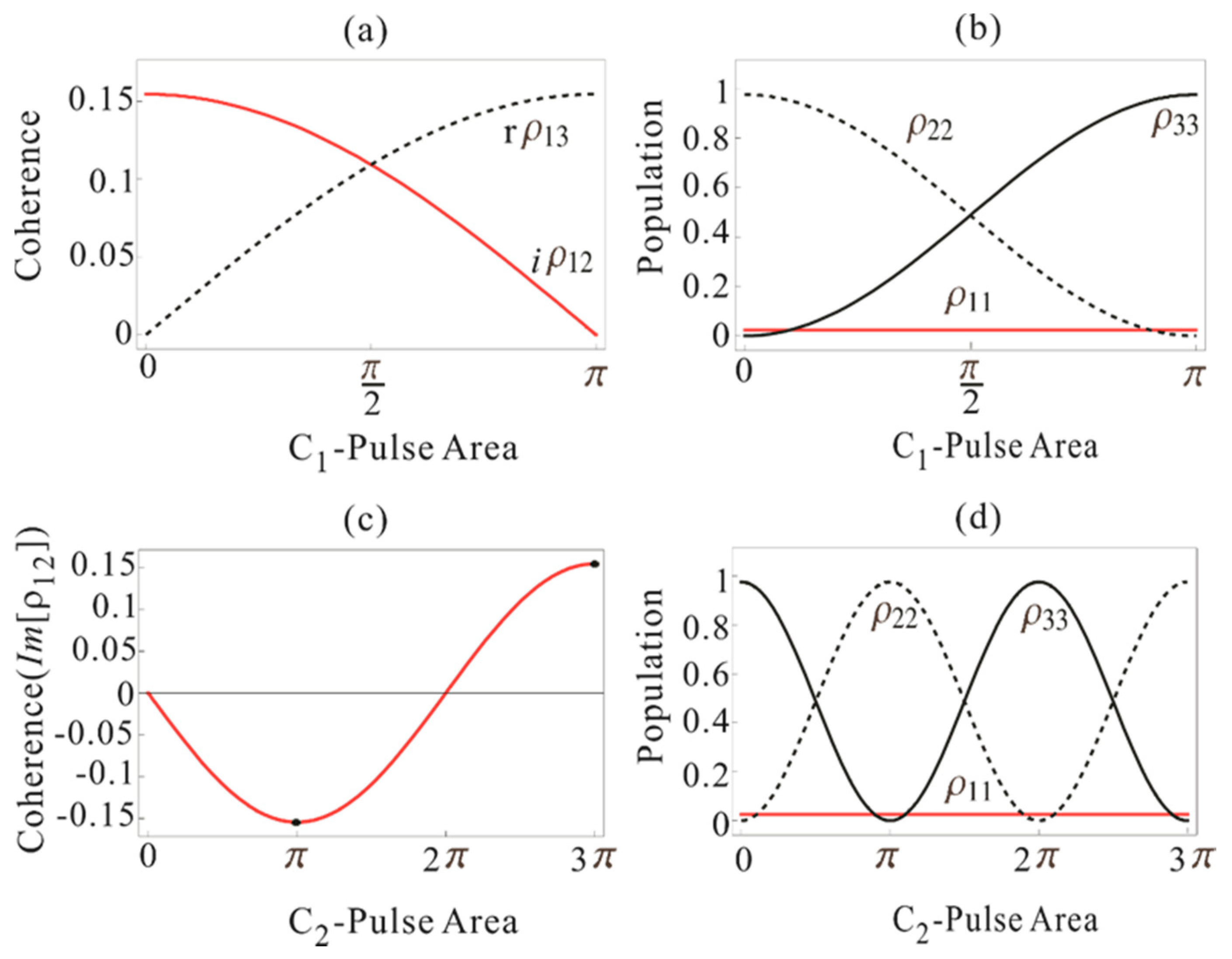
3.2.1. C1-Pulse
3.2.2. C2-Pulse
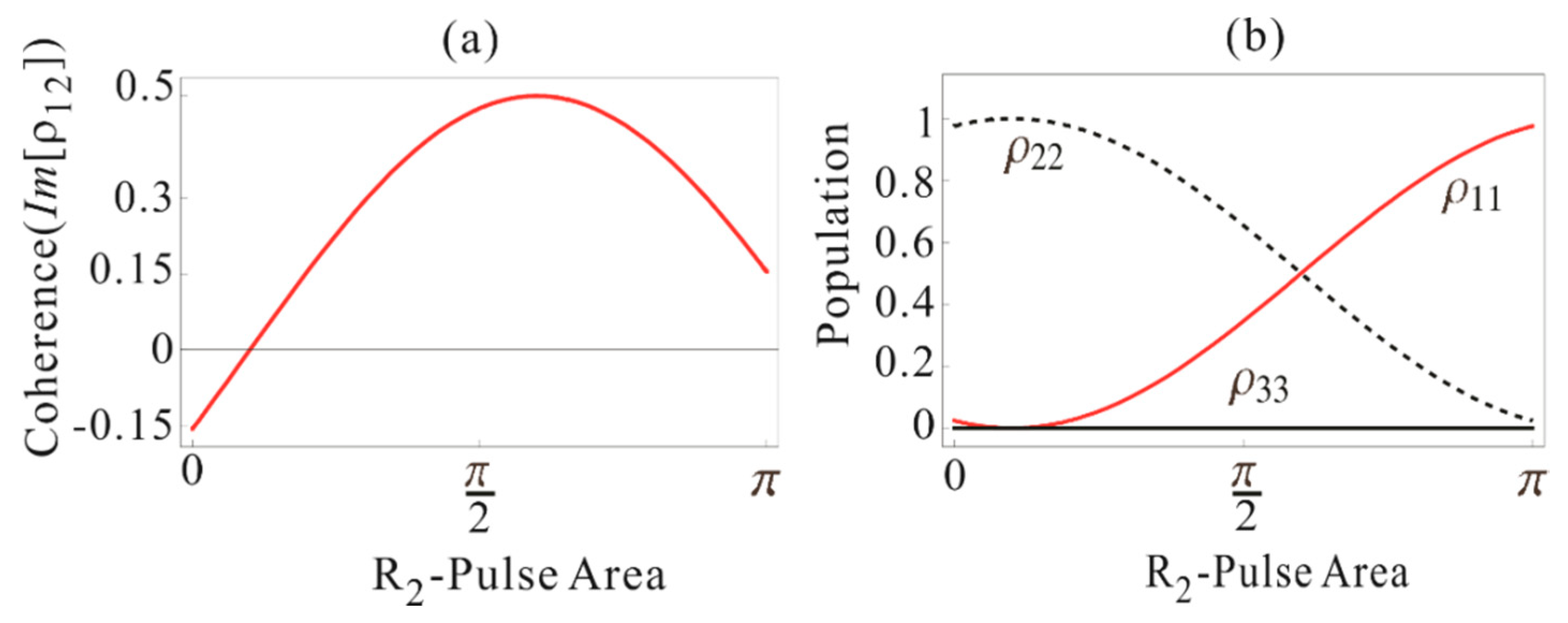
3.2.3. R2-Pulse
4. Conclusions
Author Contributions
Funding
Conflicts of Interest
Appendix A

References
- Moiseev, S.A.; Kröll, S. Complete reconstruction of the quantum state of a single-photon wave packet absorbed by a Doppler-broadened transition. Phys. Rev. Lett. 2001, 87, 173601. [Google Scholar] [CrossRef]
- Moiseev, S.A.; Tarasov, V.F.; Ham, B.S. Quantum memory photon echo-like techniques in solids. J. Opt. B Quantum Semiclassical Opt. 2003, 5, S497–S502. [Google Scholar] [CrossRef]
- Kurnit, N.A.; Abella, I.D.; Hartmann, S.R. Observation of a photon echo. Phys. Rev. Lett. 1964, 13, 567. [Google Scholar] [CrossRef]
- Wootter, W.K.; Zurek, W.H. A single quantum cannot be cloned. Nature 1982, 299, 802. [Google Scholar] [CrossRef]
- Togan, E.; Chu, Y.; Trifonov, A.; Jiang, L.; Maze, J.; Childress, L.; Dutt, M.V.G.; Sørensen, A.S.; Hemmer, P.R.; Zibrov, A.; et al. Quantum entanglement between an optical photon and a solid-state spin qubit. Nature 2010, 466, 730. [Google Scholar] [CrossRef] [Green Version]
- Macfarlane, M.R.; Shelby, R.M. Coherent transient and holeburning spectroscopy of rare earth ions in solids. In Spectroscopy of Solids Containing Rare Earth Ions; Kaplyanskii, A., Macfarlane, R.M., Eds.; Elsevier: Amsterdam, The Netherlands, 1987. [Google Scholar]
- Riedmatten, H.; Afzelius, M.; Staudt, M.U.; Simon, C.; Gisin, N. A solid-state light-matter interface at the single-photon level. Nature 2008, 456, 773. [Google Scholar] [CrossRef]
- Tittel, W.; Afzelius, M.; Chanelière, T.; Cone, R.; Kröll, S.; Moiseev, S.; Sellars, M.J. Photon-echo quantum memory in solid state systems. Laser Photon. Rev. 2010, 4, 244. [Google Scholar] [CrossRef]
- Hétet, G.; Longdell, J.J.; Alexander, A.L.; Lam, P.K.; Sellars, M.J. Electro-optic quantum memory for light using two-level atoms. Phys. Rev. Lett. 2008, 100, 023601. [Google Scholar] [CrossRef] [Green Version]
- Hedges, M.P.; Longdell, J.J.; Li, Y.; Sellars, M.J. Efficient quantum memory for light. Nature 2010, 465, 1052. [Google Scholar] [CrossRef]
- Ham, B.S. Atom phase controlled noise-free photon echoes. arXiv 2011, arXiv:1101.5480v2. [Google Scholar]
- Ham, B.S. Collective atom phase controls in photon echoes for quantum memory applications I: Population inversion removal. Adv. Appl. Sci. Res. 2018, 9, 32. [Google Scholar]
- Ham, B.S. A wavelength-convertible quantum memory: Controlled echo. Sci. Rep. 2018, 8, 10675. [Google Scholar] [CrossRef]
- Duan, L.-M.; Lukin, M.D.; Cirac, J.I.; Zoller, P. Long-distance quantum communication with atomic ensembles and liner optics. Nature 2001, 414, 413. [Google Scholar] [CrossRef] [Green Version]
- Sangouard, N.; Simon, C.; Riedmatten de, H.; Gisin, N. Quantum repeaters based on atomic ensembles and linear optics. Rev. Mod. Phys. 2011, 83, 33. [Google Scholar] [CrossRef] [Green Version]
- Longdell, J.J.; Fraval, E.; Sellars, M.J.; Manson, N.B. Stopped light with storage times greater than one second using electromagnetically induced transparency in a solid. Phys. Rev. Lett. 2015, 95, 063601. [Google Scholar] [CrossRef] [Green Version]
- Ham, B.S. Ultralong quantum optical data storage using an optical locking technique. Nat. Photon. 2009, 3, 518. [Google Scholar] [CrossRef]
- Ham, B.S. Coherent control of collective atom phase for ultralong, inversion-free photon echoes. Phys. Rev. A 2012, 85, 049905. [Google Scholar] [CrossRef] [Green Version]
- Langer, L.; Poltavtsev, S.V.; Yugova, I.A.; Salewski, M.; Yakovlev, D.R.; Karczewski, G.; Wojtowicz, T.; Akimov, I.A.; Bayer, M. Access to long-term optical memories using photon echoes retrieved from semiconductor spin. Nat. Photon. 2014, 8, 851. [Google Scholar] [CrossRef]
- Ham, B.S. Atom phase-locked coherence conversion using optical locking for ultralong photon storage beyond the spin T2 constraint. New J. Phys. 2012, 14, 013003. [Google Scholar] [CrossRef]
- Damon, V.; Bonarota, M.; Louchet-Chauvet, A.; Chanelière, T.; Le Gouët, J.-L. Revival of silenced echo and quantum memory for light. New J. Phys. 2011, 13, 093031. [Google Scholar] [CrossRef]
- Arcangeli, A.; Ferrier, A.; Goldner, P. Stark echo modulation for quantum memories. Phys. Rev. A 2016, 93, 062303. [Google Scholar] [CrossRef] [Green Version]
- McAuslan, D.L.; Ledingham, P.M.; Naylor, W.R.; Beavan, S.E.; Hedges, M.P.; Sellars, M.J.; Longdell, J.J. Photon-echo quantum memories in inhomogeneously broadened two-level atoms. Phys. Rev. A 2011, 84, 022309. [Google Scholar] [CrossRef] [Green Version]
- Ham, B.S. Gaussian beam profile effectiveness on double rephasing photon echoes. arXiv 2017, arXiv:1701.04291. [Google Scholar]
- Ham, B.S. Control of photon storage time using phase locking. Opt. Exp. 2010, 18, 1704. [Google Scholar] [CrossRef]
- Ullah, R.; Ham, B.S. Understanding of collective atom phase control in modified photon echoes for a near-perfect storage time-extended quantum memory. Entropy 2020, 22, 900. [Google Scholar] [CrossRef]
- Hahn, J.; Ham, B.S. Rephasing halted photon echoes using controlled optical deshelving. New J. Phys. 2011, 13, 093011. [Google Scholar] [CrossRef]
- Zhong, M.; Hedges, M.; Ahlefeldt, R.; Bartholomew, J.G.; Beavan, S.E.; Wittig, S.M.; Longdell, J.L.; Sellars, M.J. Optical addressable nuclear spin in a solid with a six-hour coherence time. Nature 2015, 517, 177. [Google Scholar] [CrossRef]
- Sargent, M., III; Scully, M.O.; Lamb, W.E., Jr. Laser Physics; Addison-Wesley: Boston, MA, USA, 1974. [Google Scholar]
- Hahn, E.L.; Shiren, N.S. Application of the area theorem to phonon echoes. Phys. Lett. A 1971, 37, 265. [Google Scholar] [CrossRef]
- Afzelius, M.; Usmani, I.; Amari, A.; Lauritzen, B.; Walther, A.; Simon, C.; Sangouard, N.; Minář, J.; De Riedmatten, H.; Gisin, N.; et al. Demonstration of atomic frequency comb memory for light with spin-wave storage. Phys. Rev. Lett. 2010, 104, 040503. [Google Scholar] [CrossRef] [Green Version]
- Fraval, E.; Sellars, M.J.; Longdell, J.J. Method of extending hyperfine coherence times in Pr3+:Y2SiO5. Phys. Rev. Lett. 2004, 922, 077601. [Google Scholar] [CrossRef] [Green Version]


© 2020 by the authors. Licensee MDPI, Basel, Switzerland. This article is an open access article distributed under the terms and conditions of the Creative Commons Attribution (CC BY) license (http://creativecommons.org/licenses/by/4.0/).
Share and Cite
Ullah, R.; Ham, B.S. Analysis of Controlled Rabi Flopping in a Double Rephasing Photon Echo Scheme for Quantum Memories. Entropy 2020, 22, 1007. https://doi.org/10.3390/e22091007
Ullah R, Ham BS. Analysis of Controlled Rabi Flopping in a Double Rephasing Photon Echo Scheme for Quantum Memories. Entropy. 2020; 22(9):1007. https://doi.org/10.3390/e22091007
Chicago/Turabian StyleUllah, Rahmat, and Byoung S. Ham. 2020. "Analysis of Controlled Rabi Flopping in a Double Rephasing Photon Echo Scheme for Quantum Memories" Entropy 22, no. 9: 1007. https://doi.org/10.3390/e22091007