1. Introduction
High-entropy alloys (HEAs) have recently drawn increased interest because of their distinct compositions, microstructures, and flexible properties. In contrast to conventional alloys, HEAs are composed of more than five principal elements at equal or nearly equal atomic percentages (at.%). HEAs exerts four primary effects: (1) high-entropy effect; (2) sluggish diffusion effect; (3) severe lattice distortion effect; and (4) cocktail effect [
1,
2,
3,
4]. These effects render HEAs more likely to form a simple solid-solution structure rather than an intermetallic compound, which confers distinct properties on HEAs, including high fatigue strength [
5], high hardness [
6], good abrasion resistance and corrosion resistance, high breaking strength at low temperatures [
7,
8,
9,
10], and good softening resistance at elevated temperatures [
11]. The use of HEAs as structural materials under extreme environments has been proposed owing to their desirable mechanical properties and thermodynamic stability.
Previous studies on the irradiation effects of HEAs have mostly focused on irradiation resistance and phase stability. Zhang et al. [
12] evaluated the effects of irradiation on Al
xCoCrFeNi (x = 0.1, 0.75, and 1.5) HEAs under 3 MeV Au
+ ion irradiation at room temperature. Results indicated that compared with conventional nuclear materials, single-phase HEAs based on the face-centered cubic (FCC) structure in the Al
xCoCrFeNi system showed improved radiation resistance; in addition, volume swelling in the Al
xCoCrFeNi alloys in the ascending order was FCC < FCC + BCC < BCC (body-centered cubic). Yang et al. [
13] recently reported that with temperature increased from 523 K to 923 K, the irradiation-induced defect density of Al
0.1CoCrFeNi HEAs decreased, whereas the size of the defect increased. Meanwhile, irradiation led to Ni and Co enrichment as well as Fe, Cr, and Al depletion in dislocation loops and dislocation regions. T. Nagase. et al. [
14] showed that as-sputtered CoCrFeMnNi HEAs maintained good irradiation resistance within a wide temperature range from 298 to 773 K without grain coarsening under fast electron irradiation. Jin et al. studied a Ni-based multicomponent alloy under 3 MeV Ni ion irradiation at 773 K [
15,
16] and found that irradiation-induced volume swelling decreased with an increase in the number of elements in the disordered solid solution under identical irradiation conditions. This finding suggested that irradiation-induced volume swelling was also strongly affected by compositional complexity.
In the last decade, FeCoNi-based HEAs, as one of the successful HEAs, have attracted more and more attention, especially because of its mechanical properties and microstructure evolution [
17]. M. Klimova et al. [
18] studied the microstructure and mechanical properties evolution of the Al-, C-containing CoCrFeNiMn-type high-entropy alloy during cold rolling. They reported that rolling resulted in an increase in strength and a decrease in ductility of the Al-, C-containing CoCrFeNiMn-type alloy. Feng et al. [
19] found that the short range order is positive between Al-Al, Al-Si, Si-Si pairs and negative between Ni-Al, Co-Si, Fe-Co, Ni-Si, and Fe-Si pairs, which leads to an increase in the elastic modulus by sacrificing ductility and isotropy. In addition, the appropriate doping of Y
2O
3 as a reinforcement phase in CoCrFeMnNi HEAs could increase both the room temperature tensile strength and the wear-resistance [
20].
With regard to the irradiation response of HEAs, there are not many researches on the evolution of mechanical properties of FeCoNi-based HEAs after irradiation. Meanwhile, most studies focused on the effect of composition on irradiation-induced swelling and vertical inhomogeneity of radiation damage, and the difference in irradiation response between the phase and phase boundary has rarely been reported. Whether lateral inhomogeneity of irradiation response exists in the HEAs, especially in single-phase FCC structure-based HEAs, has yet to be determined. In the present study, a typical single-phase FCC structure-based CoCrFeCuNi HEA was selected, and the key objective is to determine the irradiation response exerted by He+ ion irradiation. The present study provides an initial examination of the fundamental irradiation behavior of an HEA material, thus offering an insight into the potential of this family of materials for application under extreme environments.
2. Materials and Methods
CoCrFeCuNi HEAs with a diameter of 5 mm and a length of 100 mm were prepared by arc melting a mixture of pure metal (purity > 99.9% wt %) in a Ti-gettered high-purity argon atmosphere. These ingots were remelted at least four times to prevent chemical heterogeneity and were eventually drop-cast into a copper mold. The cast bar was cut into thin pieces, each with a thickness of 2 mm, and then mechanically polished to a mirror finish. Irradiation experiments were conducted in a BNU-400 kV electrostatic accelerator in a test chamber, applying pressure near or below 10−5 torr. The polished samples were irradiated with a 100 keV He+ ion beam at fluences of 2.5 × 10¹⁷ ions/cm2, 5.0 × 10¹⁷ ions/cm2, and 1.0 × 10¹⁸ ions/cm2 at a normal angle at room temperature.
Figure 1 shows the results for ion distribution, irradiation damage (displacement per atom or dpa), and concentration of He atoms with the increases in depth calculated using the Ion Distribution and Quick Calculation of Damage mode in the SRIM (Stopping and Range of Ions in Matter) 2008 code [
21]. As shown in
Figure 1a, when a large number of incident ions enter the HEAs, they form a spatial influence area rather than a specific path owing to collision cascade. The total number of ions is 99,999, and the effective depth of ion influence is ~560 nm. The dpa is determined by the sum of the predicted Co, Cr, Cu, Fe, and Ni vacancy concentrations and recoil events within 0 nm to ~560 nm from the surface. According to
Figure 1b,c, the three curves in each figure linearly change with increased ion doses, implying that the dpa and concentration of He atoms are positively correlated with the total doses of incident ions. Equations (1) and (2) present the method used to extract the irradiation damage (total vacancies produced/atom = dpa) and He atom concentration (in at.%) from SRIM output files [
21].
In addition, the number of atomic displacements reached the peak at a depth of approximately 290 nm, which corresponded to the projected range of the He+ ions in CoCrFeCuNi HEAs. The peak concentrations of the He atoms were approximately 14.9%, 29.8%, and 59.6% under different doses.
The phase structures of pristine and irradiated samples were analyzed by slow-scan X-Ray diffraction (XRD, Philips PW 1050 diffractometer with CuKα radiation, Amsterdam, Netherlands) at 45 kV voltage, 0.01 step size, and 200 mA current for phase analysis with improved accuracy. The microstructure and compositions of pristine and irradiated samples were analyzed by scanning electron microscopy (SEM, HITACHI S-4800, Tokyo, Japan) taken at a working voltage of 20.0 kV and a working distance of 14.3 and 15.0 mm, with energy-dispersive X-ray spectroscopy (EDX, HORIBA X-Max, Kyoto, Japan).
Nanoindentation experiments on pristine and irradiated samples were conducted using the Agilent Technologies Nano Indenter G200 with a stand Berkovich diamond indenter at room temperature (29.0 °C). The hardness measurement parameter included a strain rate of ~0.05 s−1, frequency of ~45 Hz, and harmonic displacement of ~2.0 nm. Each nanoindentation test ran to a maximum of 1000 nm into the indented surface, and all hardness measurement positions were in the matrix phases. Specifically, the sample irradiated at fluences of up to 1.0 × 10¹⁸ ions/cm2, the hardness measurement positions were located apart from the exfoliation of the damaged areas, that is, on the remaining part underneath. The geometry of the tip was standardized from the indentation on fused silica with the same indentation depth, and each sample was subjected to 5 indents with a space wider than 50 μm.
3. Results
3.1. Microstructural Characterization
The XRD patterns of the pristine and irradiated CoCrFeCuNi HEA samples at different doses are presented in
Figure 2. The figure reveals that the samples remained fully crystalline, and the diffraction peaks of CoCrFeCuNi HEAs in both pristine and irradiated samples at 43°, 50°, and 74° are from the typical FCC phases corresponding to (111), (200), and (220) lattice planes, respectively. These findings are similar to those in previous studies [
22,
23].
Figure 2 shows that no obvious phase decomposition occurs under any irradiation condition, which is consistent with high configurational entropy playing a significant role in single-phase stability [
24]. A closer examination reveals that each major peak contains two slightly separated peaks. The left peak of the major split peaks is attributed to the Cu-rich phases, whereas the right peak is attributed to the matrix phases. These findings are consistent with the following EDX results. The separated major peaks are hardly differentiated at low angles because no significant difference in average atomic radius between the Cu-rich phases and matrix phases in CoCrFeCuNi HEA is indicated. Moreover, the diffraction peaks of the irradiated HEAs shift to the left, meaning a slight lattice expansion happens. Meanwhile, the intensity of the diffraction peaks decreases with the increasing of irradiation dose, owing to the increased concentration of defects in the near surface of HEAs.
Irradiation has been known to enhance diffusion in solids by creating defects, such as vacancies and interstitials. These defects fill the irradiated layer with voids, eventually leading to a decrease in crystallinity. Irradiation-induced defects generally lead to structural damage in the HEAs, such as cluster of small defects and dislocation loops [
25]. According to Makinson et al. [
26], the peak diffraction intensity of X-rays depends on the concentration of defects in a material. Meanwhile, peak intensity decreases with an increase in defect concentration, and vice versa. In the present study, the defect concentration induced by He
+ ion irradiation increases with an increase in irradiation dose of up to 1.0 × 10
18 ions/cm
2, leading to a decrease in peak intensity. Moreover, the low solubility of helium in CoCrFeCuNi HEAs leads to its precipitation into bubbles and voids [
27], further decreasing the peak intensities.
3.2. Surface Topography
The SEM images reveal the surface morphology of pristine and irradiated CoCrFeCuNi HEAs at different irradiation doses, as shown in
Figure 3a–d.
Table 1 shows the components of different regions in the microstructures of pristine and irradiated CoCrFeCuNi alloys estimated by EDX spectroscopy. The analysis was conducted on five pristine and five irradiated regions randomly chosen from the samples. The EDX maps showing the elemental distribution of Cr, Co, Fe, Cu, and Ni on the HEAs surface at different doses, are shown in
Figure 4a–d, respectively. The EDX maps show matrix phases enriched with Cr, Fe, Co, and Ni, as well as Cu-rich phases at the phase boundaries with fair amounts of Ni, and no obvious diffusion occurs in the HEA components after irradiation, implying that the composition of HEA is stable after irradiation to some extent. Nevertheless, the distribution of the elements is very homogeneous in both the matrix phases and Cu-rich phases. Moreover, both the matrix phases and Cu-rich phases consist of only one simple phase, which is consistent with previous studies [
28]. According to
Figure 3b–d, when the irradiation dose increases to 5.0 × 10
17 ions/cm
2, the volume swelling of the Cu-rich phases markedly increases in severity. Meanwhile, no significant change is observed in the matrix phases, suggesting the inhomogeneity of radiation resistance on the surface perpendicular to the ion incident direction. The evolution of volume swelling after irradiation is discussed in the subsequent section.
However, at a dose of 1.0 × 10
18 ions/cm
2, cracking and exfoliation occur, and the subsurface becomes visible after the surface flakes off. Wei et al. [
29] reported a similar occurrence on Cu
48Zr
48Al
4 bulk metallic glass composites induced by He
+ ion irradiation at the same dose. When high-energy He
+ ions are bombarded at a target material, most ions take electrons from the matrix to form helium atoms, which can cause distortion, elastic rebound, and stress in the lattice [
30]. With increasing irradiation fluence, irradiation-induced helium gas pressure develops inside the matrix. At a fluence of 1.0 × 10
18 ions/cm
2, excessive pressure of the helium gas was developed inside the irradiated area, which eventually led to cracking and exfoliation [
31,
32], as shown in
Figure 3d.
3.3. Mechanical Behavior
A nanoindentation test was conducted to reveal the average microhardness of the HEA surface and thus investigate the irradiation-induced hardening behavior.
Figure 5 shows typical (a) depth profiles of nanoindentation hardness and (b) dependence of the H
irr/H
unirr ratio on the indentation depth of pristine and irradiated CoCrFeCuNi HEAs at different irradiation doses. The irradiated region and substrate region are consistent with the dpa profiles (see
Figure 1b).
Figure 5a shows that the pristine samples decrease in hardness with increasing indent depth at the indentation depth of h > 50 nm. Such depth-dependent hardness behavior is regarded as the indentation size effect (ISE) [
33]. By contrast, hardness increases with increasing indent depth at the depth of
h < 50 nm is considered as reverse ISE, which is usually caused by uncertainty factors from the surface and the geometrical shape of the Berkovich indenter. Therefore, to exclude uncertainty factors from the surface, we ignored the data in regions shallower than 100 nm in this study. Compared with pristine samples, all irradiated samples exhibited different degrees of hardening at
h > 100 nm. To more clearly characterize the degree of increment, the dependence of the H
irr/H
unirr ratio on the indentation depth of all samples is exhibited in
Figure 5b. Notably, the normalized nanoindentation hardness reaches a peak with an increase in indentation depth. The same peak position on all curves is located at a depth of ~146 nm (the dotted transition line). For the shallower region before the transition line, H
irr/H
unirr increases with an increase in indentation depth, which is similar to the results for other metals [
25] irradiated with similar ions. However, for the deeper region after the transition line, H
irr/H
unirr decreases with an increase in indentation depth.
An irradiation-induced hardened layer forms in the HEAs after He
+ ion implantation. When indented into the sample surface, the hemispheric influence zone beneath the indenter can reach 4 to 10 times the indentation depth. As the indenter presses deeper, if the radius of the influence zone is less than the thickness of the hardened layer, the damage grade effect is exerted, and the hardening ratio increases; otherwise the softer substrate effect is exerted, and the hardening ratio decreases [
34].
To explain the ISE, Nix and Gao [
35] developed a model based on the concept of geometrically necessary dislocations. This model predicts the hardness-depth profile by using the following equation.
where
H is the hardness,
h is the indentation depth,
H0 is the hardness at an infinite depth (i.e., macroscopic hardness), and
h* is the length that characterizes the depth dependence of hardness for a given material and indenter geometry, which depends on the material and shape of the indenter tip (i.e., statistically stored dislocation density) [
36]. To aid the discussion, the hardness data are plotted as
H2 versus 1/
h in
Figure 6.
H0 is the square root of the intercept for the linear fitting of the hardness data in the near-surface region. The value of
H0 excludes the size effect and can be used as a parameter to characterize the hardening effect in HEAs under irradiation.
In
Figure 6, the pristine sample shows good linearity in the range of 100 nm <
h < 1000 nm. Regardless, the irradiated samples exhibit bilinearity with a shoulder at the depth of about 150 nm consisting of the depth of the transition line, (see
Figure 6).
Table 2 lists
H0 and
h* for the pristine samples and irradiated samples calculated by least squares fitting of hardness data in the 100 nm <
h < 1000 nm range according to Equation (3) [
37].
The data in
Table 2 shows that the calculated
H0 first increases and then decreases with an increase in irradiation dose, which is consistent with the hardness results. The calculated
h* decreases systematically, implying a smaller size effect during irradiation, which is consistent with previous studies [
37].
4. Discussion
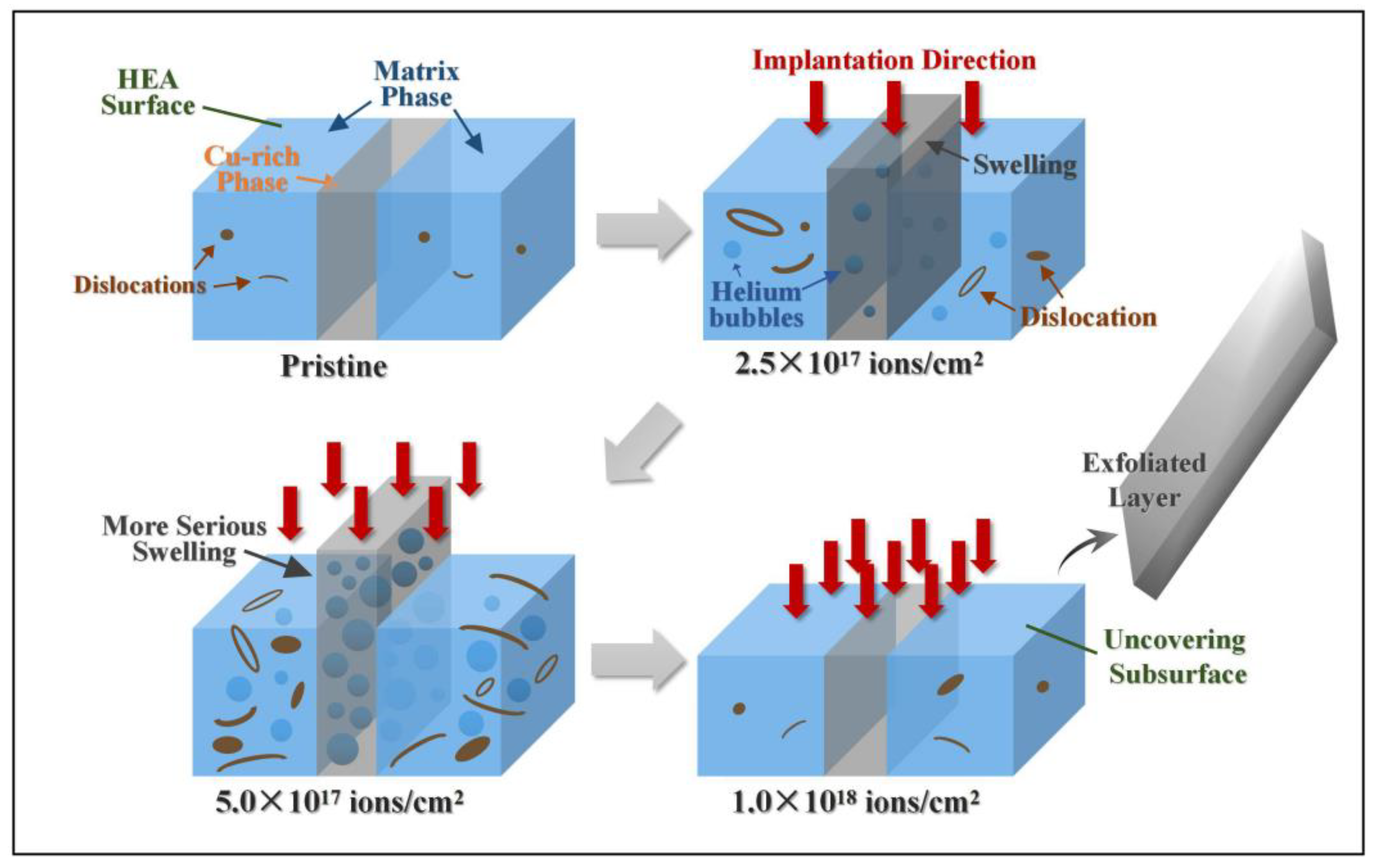
The schematic in
Figure 7 illustrates the swelling effect, as well as the hardening behavior, of Cu-rich phases during He
+ irradiation. With regard to the formation of He bubbles, nuclear loss-induced collisional damage, such as dislocations, voids, and interfaces, act as sinks for point defects. Dislocations can partly absorb more interstitials than vacancies. A large number of vacancies are consequently generated in the HEAs, and vacancy clusters grow and trap He to form He bubbles. For CoCrFeCuNi HEA, the Cu-rich phases appeared as defect-rich phase boundary regions in the matrix phases, similar to grain boundary, which are also favorable nucleation sites of He bubbles [
38]. With the ion dose increasing to 5.0 × 10
17 ions/cm
2, the He concentration increasingly rises and reaches near-saturation [
39] in the matrix phases. Thus, He bubbles tend to migrate and gather toward the Cu-rich phases, resulting in the increased severity of volume swelling, as shown in
Figure 7. We also reported that the irradiation response is inhomogeneous along the ion incident direction because of a perpendicular local shear stress [
40]. Cu-rich phases may act as local low-stress regions because of the more loosely packed He atoms. He bubbles may thus preferentially migrate toward the Cu-rich phases to unload the stress, resulting in the increased severity of volume swelling [
41,
42]. This factor can be potentially influence the volume swelling of Cu-rich phases.
At ion doses ranging from 2.5 × 10
17 ions/cm
2 to 5.0 × 10
17 ions/cm
2, HEAs exhibit marked hardening behavior, which can be attributed to obstacles to dislocation glide, proposed by Orowan and Seeger [
43,
44]. In general, irradiation-induced defect clusters and/or dislocation loops, as well as He bubbles, pin dislocation lines and impede dislocation glide, causing HEAs to harden [
45]. However, as previously mentioned, as the irradiation dose increases, numerous He bubbles migrate and gather toward the Cu-rich phases to form cavities, which may induce swelling and softening of the Cu-rich phases. While the irradiation-induced dislocations continue to increase in the matrix phases, the overall result for the HEA ultimately reflects the hardening effect.
When the ion dose increases to 1.0 × 10
18 ions/cm
2, the hardness of the HEA slightly decreases. To avoid surface irregular interference, we selected the flatter subsurface for hardness testing. Consistent with the SEM micrograph in
Figure 3d, at the highest dose, the uncovering of the subsurface after exfoliation corresponds to a new irradiation plane, except that it is only affected by diminished irradiation effects, and therefore the hardness decreases. In addition, recovery [
46,
47,
48] might occur during irradiation. The thermal-spike effect during long-term irradiation can lead to annealing of defects and annihilation of helium bubbles, thus reducing the hardening effect. We hypothesize that the weakened irradiation effect on the uncovering subsurface, combined with recovery, causes softening of the HEA.
5. Conclusions
CoCrFeCuNi HEAs prepared by arc melting were irradiated with a 100 keV He+ ion beam at fluences of 2.5 × 10¹⁷ ions/cm2, 5.0 × 10¹⁷ ions/cm2, and 1.0 × 10¹⁸ ions/cm2 at room temperature. XRD results proved that all diffraction peak intensities along the (111), (200), and (220) lattice planes decreased regularly, indicating that the irradiated layer was filled with voids, leading to a decrease in crystallinity. When the irradiation dose increased to 5.0 × 10¹⁷ ions/cm2, the irradiation-induced swelling became increasingly severe in the Cu-rich phases, whereas no significant change occurred in the matrix phases. This difference suggested that the degree of swelling varied between the two phases under the same irradiation condition. This finding contributed to the migration and gathering of the He bubble-induced noncompact structure and the lateral inhomogeneity of radiation damage. At a higher dose, 1.0 × 10¹⁸ ions/cm2, cracking and exfoliation occurred revealing the subsurface after the surface flaked off mainly from the excessive pressure of the He gas. Nanoindentaion was performed to indicate that hardening induced by He+ ion irradiation occurred in both irradiated samples. The depth-dependent hardness behavior was explained by the Nix-Gao model. At ion doses of 2.5 × 10¹⁷ ions/cm2 and 5.0 × 10¹⁷ ions/cm2, the HEAs exhibited an obvious hardening behavior, which can be explained by dislocation-dominated hardening effect. When the ion dose reached 1.0 × 10¹⁸ ions/cm2, the hardening effect decreased probably because of the weakened irradiation effect on the uncovered subsurface, combined with the long-term thermal-spike effect-induced recovery.
Author Contributions
Conceptualization, K.Z. and Y.W.; software, W.T.; validation, B.W., K.Z. and Y.W.; formal Analysis, Y.W.; investigation, Y.W. and Y.L.; resources, B.W.; data curation, Y.W. and Y.F.; writing-original draft preparation, Y.W.; writing-review & editing, Y.W. and K.Z.; visualization, Y.W.; supervision, B.W. and K.Z.; project administration, B.W.
Funding
This research was funded by the National Natural Science Foundation of China (Grant No. 51401028, No. 51271193, No. 11402277, No. 11790292) and the Strategic Priority Research Program of the Chinese Academy of Sciences (Grant No. XDB22040303).
Conflicts of Interest
The authors declare no conflict of interest.
References
- Zhang, Y.; Zuo, T.T.; Tang, Z.; Gao, M.C.; Dahmen, K.A.; Liaw, P.K.; Lu, Z.P. Microstructures and properties of high-entropy alloys. Prog. Mater. Sci. 2014, 61, 1–93. [Google Scholar] [CrossRef]
- Yeh, J.-W.; Chen, S.-K.; Lin, S.-J.; Gan, J.-Y.; Chin, T.-S.; Shun, T.-T.; Tsau, C.-H.; Chang, S.-Y. Nanostructured high-entropy alloys with multiple principal elements: Novel alloy design concepts and outcomes. Adv. Eng. Mater. 2004, 6, 299–303. [Google Scholar] [CrossRef]
- Zhang, Y.; Zhou, Y.J.; Lin, J.P.; Chen, G.L.; Liaw, P.K. Solid-solution phase formation rules for multi-component Alloys. Adv. Eng. Mater. 2008, 10, 534–538. [Google Scholar] [CrossRef]
- Yang, X.; Zhang, Y. Prediction of high-entropy stabilized solid-solution in multi-component alloys. Mater. Chem. Phys. 2012, 132, 233–238. [Google Scholar] [CrossRef]
- Tang, Z.; Yuan, T.; Tsai, C.-W.; Yeh, J.-W.; Lundin, C.D.; Liaw, P.K. Fatigue behavior of a wrought Al0.5CoCrCuFeNi two-phase high-entropy alloy. Acta. Mater. 2015, 99, 247–258. [Google Scholar] [CrossRef]
- Senkov, O.N.; Senkova, S.V.; Woodward, C.; Miracle, D.B. Low-density, refractory multi-principal element alloys of the Cr–Nb–Ti–V–Zr system: Microstructure and phase analysis. Acta. Mater. 2013, 61, 1545–1557. [Google Scholar] [CrossRef]
- Huang, P.-K.; Yeh, J.-W.; Shun, T.-T.; Chen, S.-K. Multi-principal-element alloys with improved oxidation and wear resistance for thermal spray coating. Adv. Eng. Mater. 2004, 6, 74–78. [Google Scholar] [CrossRef]
- Hemphill, M.A.; Yuan, T.; Wang, G.Y.; Yeh, J.W.; Tsai, C.W.; Chuang, A.; Liaw, P.K. Fatigue behavior of Al0.5CoCrCuFeNi high entropy alloys. Acta. Mater. 2012, 60, 5723–5734. [Google Scholar] [CrossRef]
- Chuang, M.-H.; Tsai, M.-H.; Wang, W.-R.; Lin, S.-J.; Yeh, J.-W. Microstructure and wear behavior of AlxCo1.5CrFeNi1.5Tiy high-entropy alloys. Acta. Mater. 2011, 59, 6308–6317. [Google Scholar] [CrossRef]
- Gludovatz, B.; Hohenwarter, A.; Catoor, D.; Chang, E.H.; George, E.P.; Ritchie, R.O. A fracture-resistant high-entropy alloy for cryogenic applications. Science. 2014, 345, 1153. [Google Scholar] [CrossRef] [PubMed]
- Lu, Y.; Dong, Y.; Guo, S.; Jiang, L.; Kang, H.; Wang, T.; Wen, B.; Wang, Z.; Jie, J.; Cao, Z.; Ruan, H.; Li, T. A promising new class of high-temperature alloys: Eutectic high-entropy alloys. Sci. Rep.-UK 2014, 4, 6200. [Google Scholar] [CrossRef] [PubMed]
- Xia, S.Q.; Yang, X.; Yang, T.F.; Liu, S.; Zhang, Y. Irradiation resistance in AlxCoCrFeNi high entropy alloys. JOM 2015, 67, 2340–2344. [Google Scholar] [CrossRef]
- Yang, T.; Xia, S.; Guo, W.; Hu, R.; Poplawsky, J.D.; Sha, G.; Fang, Y.; Yan, Z.; Wang, C.; Li, C.; et al. Effects of temperature on the irradiation responses of Al0.1CoCrFeNi high entropy alloy. Scripta Mater. 2018, 144, 31–35. [Google Scholar] [CrossRef]
- Nagase, T.; Rack, P.D.; Noh, J.H.; Egami, T. In-situ TEM observation of structural changes in nano-crystalline CoCrCuFeNi multicomponent high-entropy alloy (HEA) under fast electron irradiation by high voltage electron microscopy (HVEM). Intermetallics 2015, 59, 32–42. [Google Scholar] [CrossRef] [Green Version]
- Jin, K.; Lu, C.; Wang, L.M.; Qu, J.; Weber, W.J.; Zhang, Y.; Bei, H. Effects of compositional complexity on the ion-irradiation induced swelling and hardening in Ni-containing equiatomic alloys. Scripta Mater. 2016, 119, 65–70. [Google Scholar] [CrossRef] [Green Version]
- Jin, K.; Sales, B.C.; Stocks, G.M.; Samolyuk, G.D.; Daene, M.; Weber, W.J.; Zhang, Y.; Bei, H. Tailoring the physical properties of Ni-based single-phase equiatomic alloys by modifying the chemical complexity. Sci. Rep. 2016, 6, 20159. [Google Scholar] [CrossRef] [PubMed] [Green Version]
- Tsai, M.-H.; Yeh, J.-W. High-Entropy Alloys: A Critical Review. Mater. Res. Lett. 2014, 2, 107–123. [Google Scholar] [CrossRef] [Green Version]
- Klimova, M.; Stepanov, N.; Shaysultanov, D.; Chernichenko, R.; Yurchenko, N.; Sanin, V.; Zherebtsov, S. Microstructure and mechanical properties evolution of the Al, C-containing CoCrFeNiMn-type high-entropy alloy during cold rolling. Materials 2017, 11, 53. [Google Scholar] [CrossRef] [PubMed]
- Feng, W.; Qi, Y.; Wang, S. Effects of short-range order on the magnetic and mechanical properties of FeCoNi (AlSi)x high entropy alloys. Metals 2017, 7, 482. [Google Scholar] [CrossRef]
- Liu, X.; Yin, H.; Xu, Y. Microstructure, mechanical and tribological properties of oxide dispersion strengthened high- entropy alloys. Materials 2017, 10, 1312. [Google Scholar] [CrossRef] [PubMed]
- Egeland, G.W.; Valdez, J.A.; Maloy, S.A.; McClellan, K.J.; Sickafus, K.E.; Bond, G.M. Heavy-ion irradiation defect accumulation in ZrN characterized by TEM, GIXRD, nanoindentation, and helium desorption. J. Nucl. Mater. 2013, 435, 77–87. [Google Scholar] [CrossRef]
- Zhu, Z.G.; Ma, K.H.; Wang, Q.; Shek, C.H. Compositional dependence of phase formation and mechanical properties in three CoCrFeNi-(Mn/Al/Cu) high entropy alloys. Intermetallics 2016, 79, 1–11. [Google Scholar] [CrossRef]
- Ma, Y.; Peng, G.J.; Wen, D.H.; Zhang, T.H. Nanoindentation creep behavior in a CoCrFeCuNi high-entropy alloy film with two different structure states. Mat. Sci. Eng. A Struct. 2015, 621, 111–117. [Google Scholar] [CrossRef]
- Kumar, N.A.P.K.; Li, C.; Leonard, K.J.; Bei, H.; Zinkle, S.J. Microstructural stability and mechanical behavior of FeNiMnCr high entropy alloy under ion irradiation. Acta Mater. 2016, 113, 230–244. [Google Scholar] [CrossRef] [Green Version]
- Odette, G.R.; Alinger, M.J.; Wirth, B.D. Recent Developments in Irradiation-Resistant Steels. Annu. Rev. Mater. Res. 2008, 38, 471–503. [Google Scholar] [CrossRef]
- Makinson, J.D.; Lee, J.S.; Magner, S.H.; Angelis, R.J.D.; Weins, W.N.; Hieronymus, A.S. X-ray Diffraction Signatures of Defects in Nanocrystalline Materials. Adv. X-Ray Anal. 2000, 42, 407–411. [Google Scholar]
- Zhang, X.; Mei, X.; Zhang, Q.; Li, X.; Wang, Y.; Wang, Y. Study of irradiation damage induced by He2+ ion irradiation in Ni62Ta38 metallic glass and W metal. Nucl. Instrum. Methods Phys. Res. Sect. B 2017, 406, 548–554. [Google Scholar] [CrossRef]
- Oh, S.M.; Hong, S.I. Microstructure and mechanical properties of equitomic CoCrFeCuNi high entropy alloy. Key Eng. Mater. 2018, 765, 149–154. [Google Scholar] [CrossRef]
- Wei, Y.; Zhang, K.; Wei, B.; Zhao, Z.; Yuan, J. Microstructural evolution and mechanical properties in Cu48Zr48Al4 bulk metallic glass composites induced by He+ ion irradiation. Nucl. Instrum. Methods Phys. Res. Sect. B 2018, 428, 17–23. [Google Scholar] [CrossRef]
- Ghauri, I.M.; Afzal, N. Effects of neutron irradiation on the stress relaxation rate in Al–Cu–Mg alloy. J. Phys. D Appl. Phys. 2007, 40, 6044. [Google Scholar] [CrossRef]
- Rafique, M.; Afzal, N.; Ahmad, R. Impact of 18 MeV He+ ions on the morphological and structural properties of pure Fe. Mater. Res. Express 2017, 4, 096504. [Google Scholar] [CrossRef]
- Zhang, X.; Mei, X.; Zhang, Q.; Li, X.; Qiang, J.; Wang, Y. Damage induced by helium ion irradiation in Fe-based metallic glass. J. Nucl. Mater. 2017, 490, 216–225. [Google Scholar] [CrossRef]
- Pharr, G.M.; Herbert, E.G.; Gao, Y. The indentation size effect: A critical examination of experimental observations and mechanistic interpretations. Annu. Rev. Mater. Res. 2010, 40, 271–292. [Google Scholar] [CrossRef]
- Liu, X.; Wang, R.; Ren, A.; Jiang, J.; Xu, C.; Huang, P.; Qian, W.; Wu, Y.; Zhang, C. Evaluation of radiation hardening in ion-irradiated Fe based alloys by nanoindentation. J. Nucl. Mater. 2014, 444, 1–6. [Google Scholar] [CrossRef]
- Nix, W.D.; Gao, H. Indentation size effects in crystalline materials: A law for strain gradient plasticity. J. Mech. Phys. Solids 1998, 46, 411–425. [Google Scholar] [CrossRef]
- Was, G.S. Fundamentals of radiation materials science: Metals and alloys. Mater. Today 2007, 10, 52. [Google Scholar]
- Kasada, R.; Takayama, Y.; Yabuuchi, K.; Kimura, A. A new approach to evaluate irradiation hardening of ion-irradiated ferritic alloys by nano-indentation techniques. Fusion Eng. Des. 2011, 86, 2658–2661. [Google Scholar] [CrossRef] [Green Version]
- Yu, K.Y.; Liu, Y.; Sun, C.; Wang, H.; Shao, L.; Fu, E.G.; Zhang, X. Radiation damage in helium ion irradiated nanocrystalline Fe. J. Nucl. Mater. 2012, 425, 140–146. [Google Scholar] [CrossRef]
- Nagata, S.; Tsuchiya, B.; Sugawara, T.; Ohtsu, N.; Shikama, T. Helium and hydrogen trapping in W and Mo single-crystals irradiated by He ions. J. Nucl. Mater. 2002, 307–311, 1513–1516. [Google Scholar] [CrossRef]
- Zhang, K.; Hu, Z.; Zhao, Z.; Wei, B.; Li, Y.; Wei, Y. Whiskers growth and self-healing in Ti-based metallic glasses during ion irradiation. Appl. Surf. Sci. 2018, 437, 176–180. [Google Scholar] [CrossRef] [Green Version]
- Van Dillen, T.; Polman, A.; Onck, P.R.; van der Giessen, E. Anisotropic plastic deformation by viscous flow in ion tracks. Phys. Rev. B 2005, 71, 024103. [Google Scholar] [CrossRef]
- Volkert, C.A. Density changes and viscous flow during structural relaxation of amorphous silicon. J. Appl. Phys. 1993, 74, 7107–7113. [Google Scholar] [CrossRef]
- Orowan, E. Symposium on Internal Stresses in Metals and Alloys; Institute of Metals: London, UK, 1948. [Google Scholar]
- Seeger, A.K. On the theory of radiation damage and radiation hardening. In Proceedings of the Second United Nations International Conference on the Peaceful Uses of Atomic Energy, Geneva, Switzerland, 1–13 September 1958; pp. 250–273. [Google Scholar]
- Ou, X.; Anwand, W.; Kögler, R.; Zhou, H.-B.; Richter, A. The role of helium implantation induced vacancy defect on hardening of tungsten. J. Appl. Phys. 2014, 115, 123521. [Google Scholar] [CrossRef] [Green Version]
- Gao, F.; Bacon, D.J.; Howe, L.M.; So, C.B. Temperature-dependence of defect creation and clustering by displacement cascades in α-zirconium. J. Nucl. Mater. 2001, 294, 288–298. [Google Scholar] [CrossRef]
- Fabritsiev, S.A.; Pokrovsky, A.S. Effect of irradiation temperature on microstructure, radiation hardening and embrittlement of pure copper and copper-based alloy. J. Nucl. Mater. 2007, 367–370, 977–983. [Google Scholar] [CrossRef]
- Miyazawa, T.; Nagasaka, T.; Kasada, R.; Hishinuma, Y.; Muroga, T.; Watanabe, H.; Yamamoto, T.; Nogami, S.; Hatakeyama, M. Evaluation of irradiation hardening of ion-irradiated V–4Cr–4Ti and V–4Cr–4Ti–0.15Y alloys by nanoindentation techniques. J. Nucl. Mater. 2014, 455, 440–444. [Google Scholar] [CrossRef]
© 2018 by the authors. Licensee MDPI, Basel, Switzerland. This article is an open access article distributed under the terms and conditions of the Creative Commons Attribution (CC BY) license (http://creativecommons.org/licenses/by/4.0/).

 ,
, 


