
2-DOF Woven Tube Plane Surface Soft Actuator Using Extensional Pneumatic Artificial Muscle

Abstract
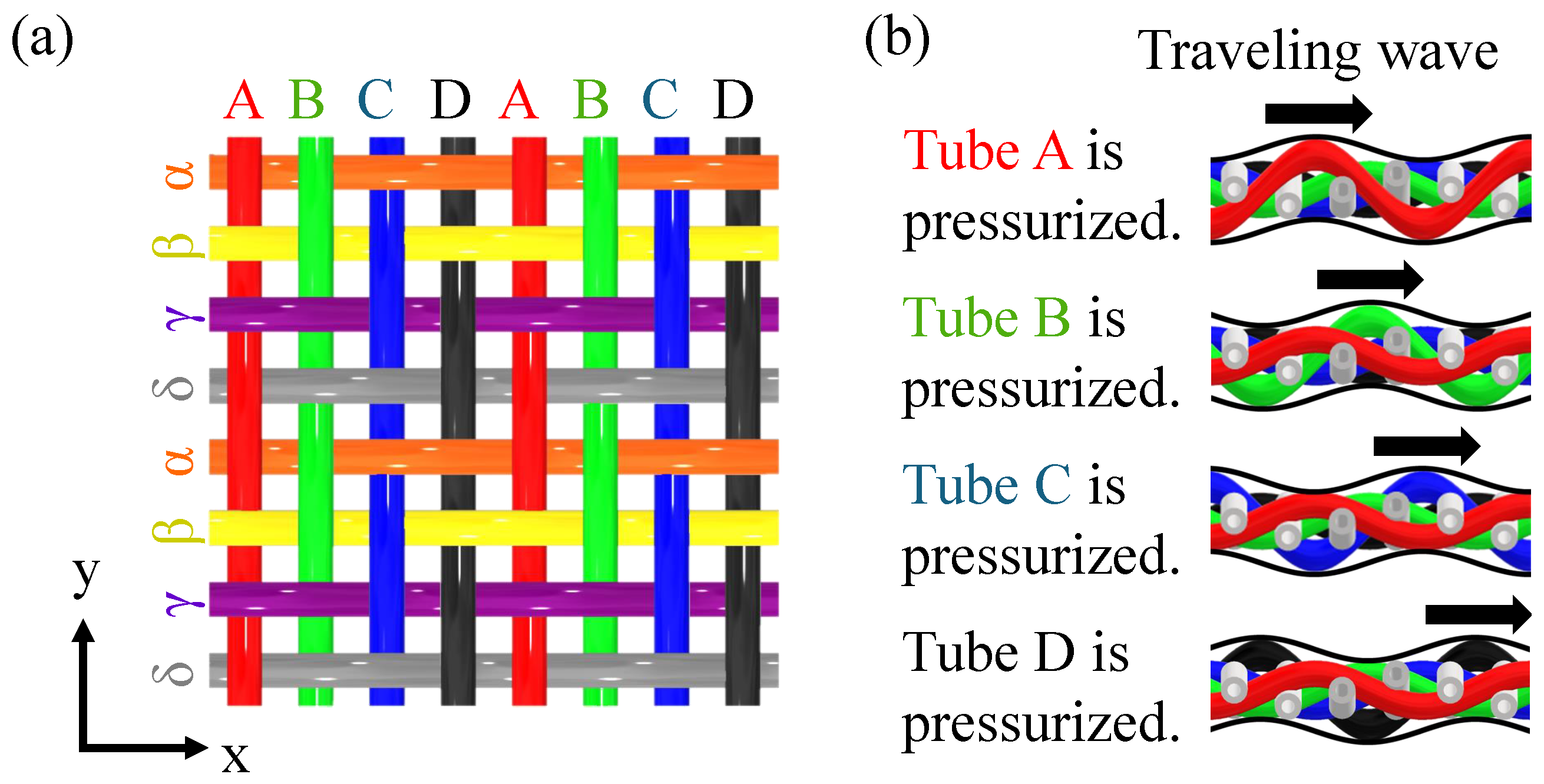
:1. Introduction
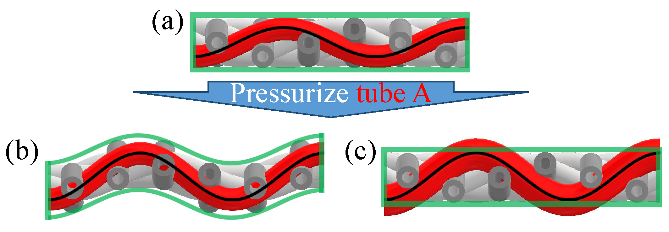
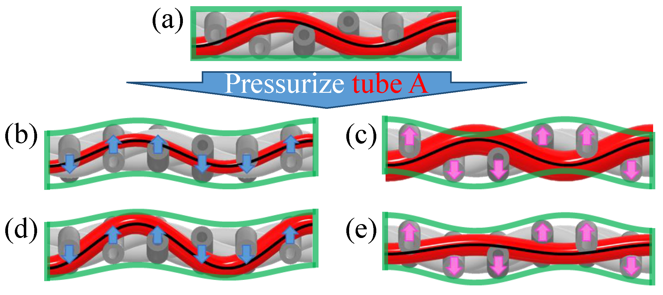
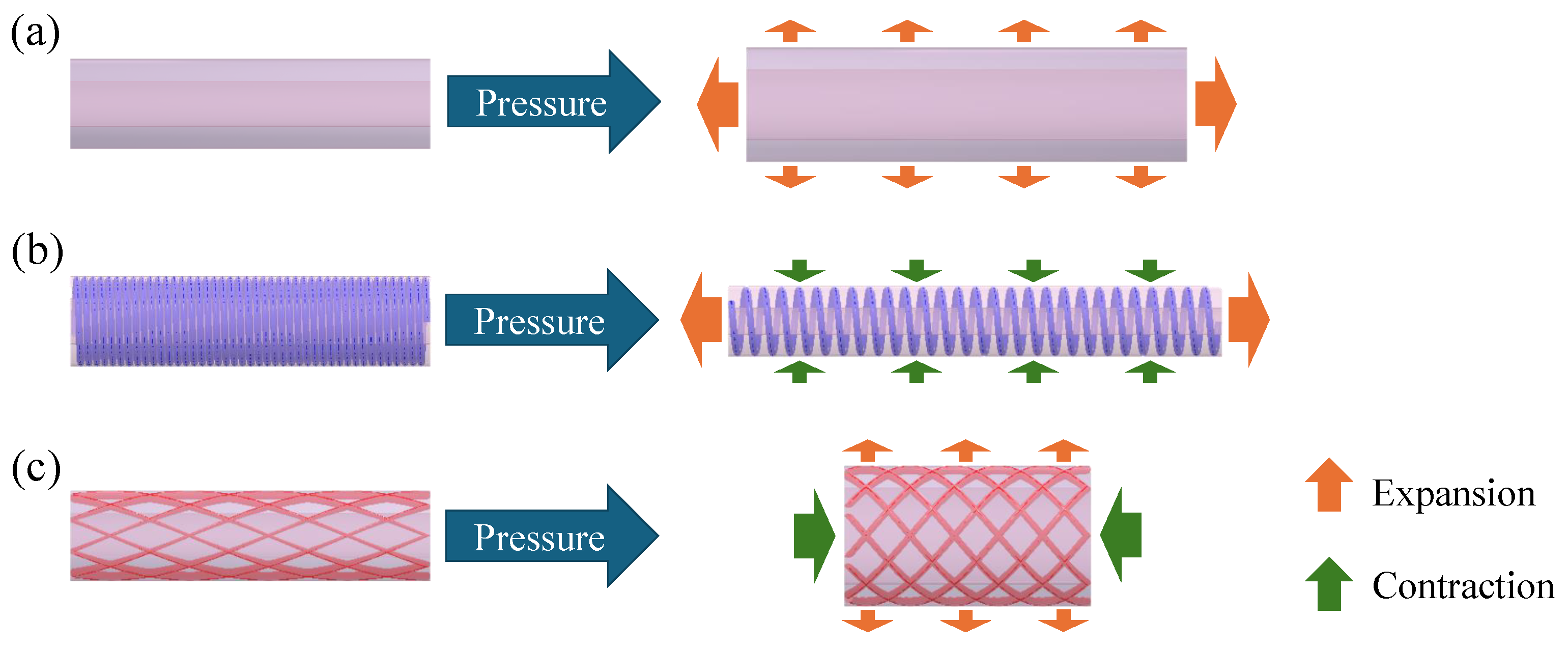
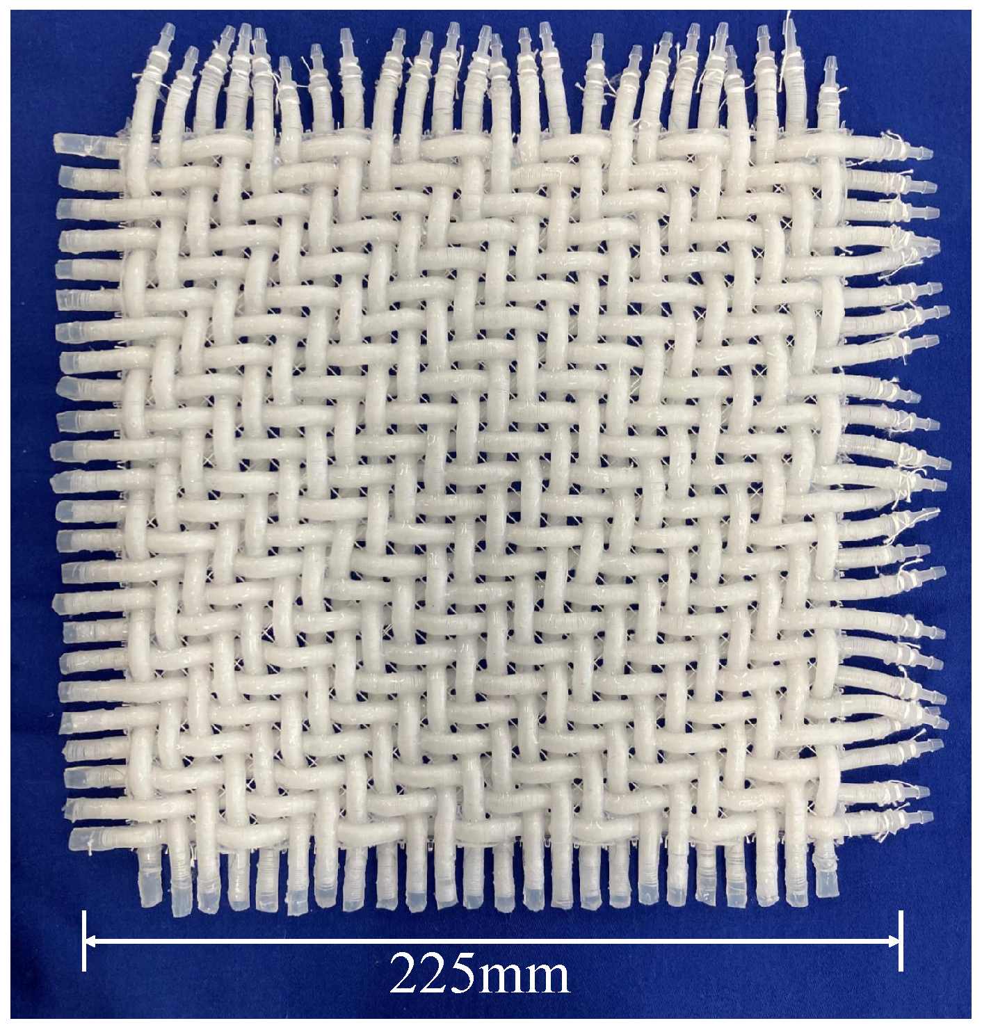
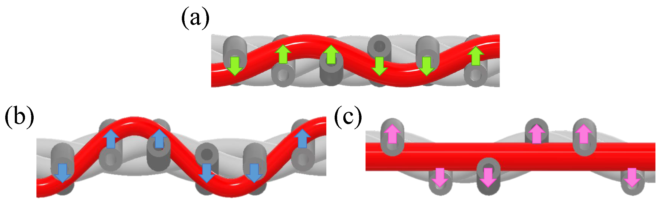
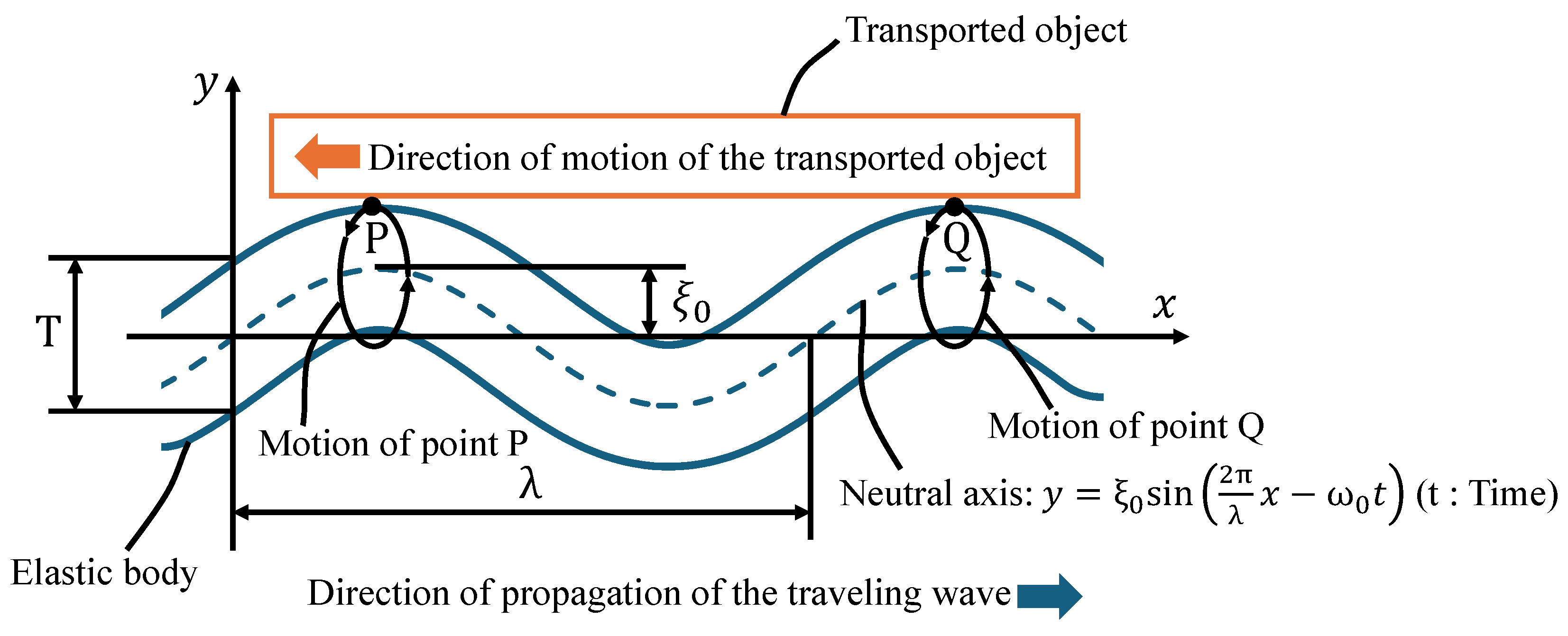
2. Design and Methods
3. Build and Operating Instructions
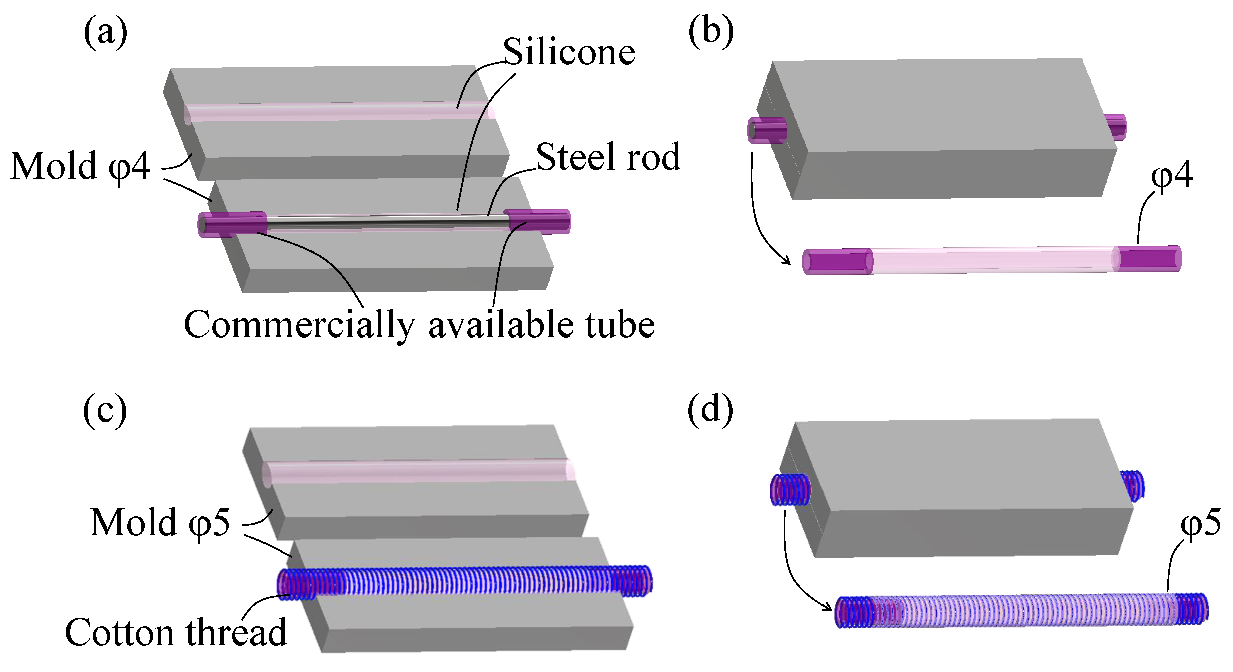
- Commercially available silicone tubes with an inner diameter of 2.5 mm, an outer diameter of 4 mm, and a length of approximately 20 mm were attached to both ends of a metal rod with a diameter of 2.5 mm and a length of 250 mm. Commercially available silicone tubes were connected to the air pressure sources when pressurizing an actuator.
- In Figure 5a, the metal rod with the attached silicone tubes was placed in one part of the mold designed for tubes with an outer diameter of 4 mm, which consisted of two parts in a set. Well-mixed two-component silicone was poured into both parts of the mold.
- In Figure 5b, two parts of the mold were assembled, and after 24 h, the hardened silicone was removed from the mold.
- The metal rod was pulled out from the silicone, and a cotton thread was wound around the silicone.
- In Figure 5c, a well-mixed two-component silicone was poured into two parts of the mold for the tubes with an outer diameter of 5 mm. From step 4, the silicone tube was placed into one part of the mold.
- In Figure 5d, the two mold parts were assembled, and after 24 h, an extensional PAM was produced.

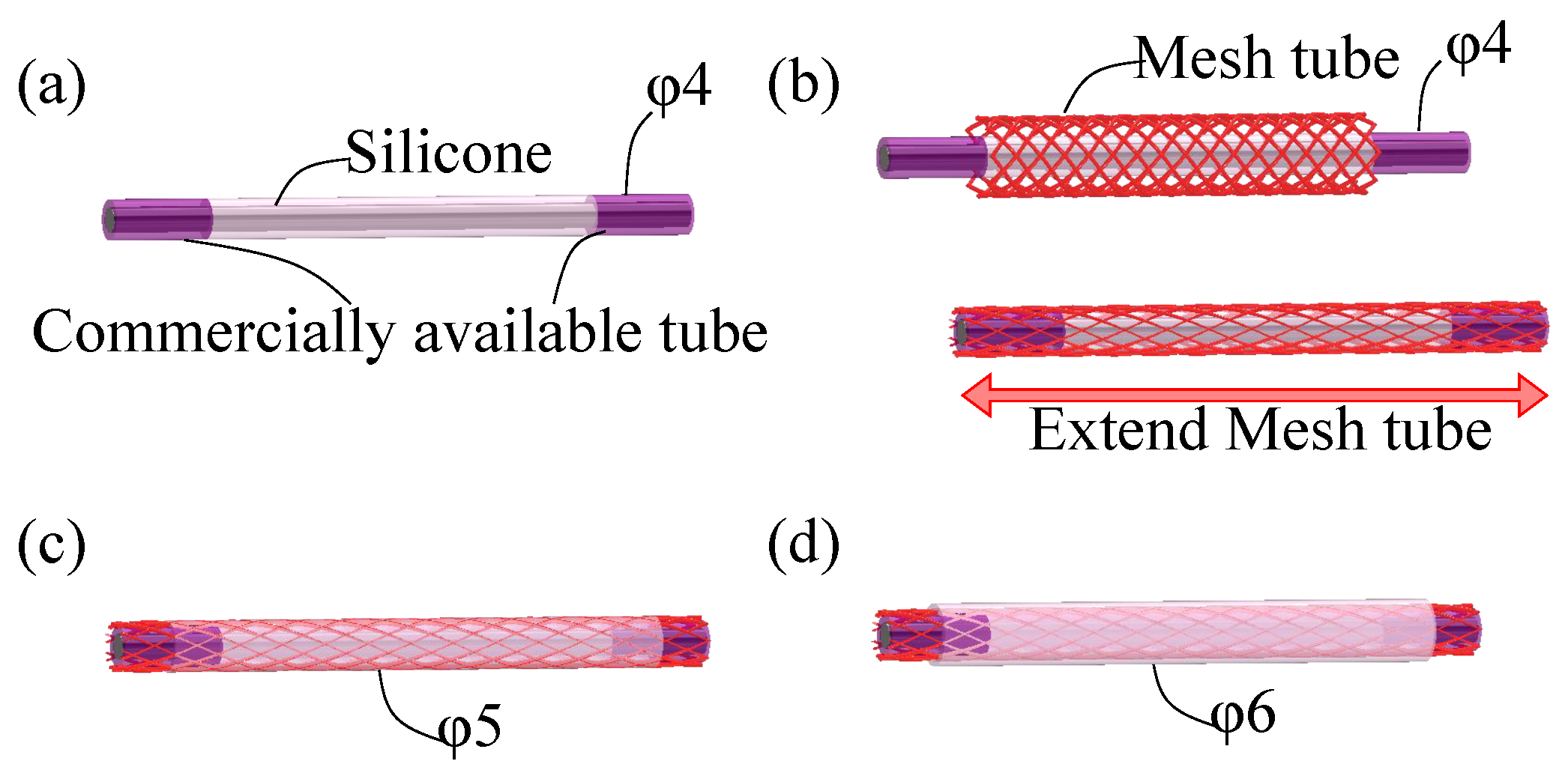
- Shown in Figure 6a, a silicone tube was created in the same way to fabricate the extensional PAM (Steps 1–3).
- Shown in Figure 6b, the silicone tube was covered with a nylon mesh tube and pulled axially from its natural length.
- A contractional PAM with an outer diameter of 5 mm was produced in the same way to fabricate the extensional PAM (Steps 5 and 6) as shown in Figure 6c.
- Using a mold designed for tubes with an outer diameter of 6 mm, an additional silicone layer was created on the outer side in the same way to fabricate the extensional PAM (Steps 5 and 6) as shown in Figure 6d.
- Finally, the metal rod was removed from the contractional PAM.

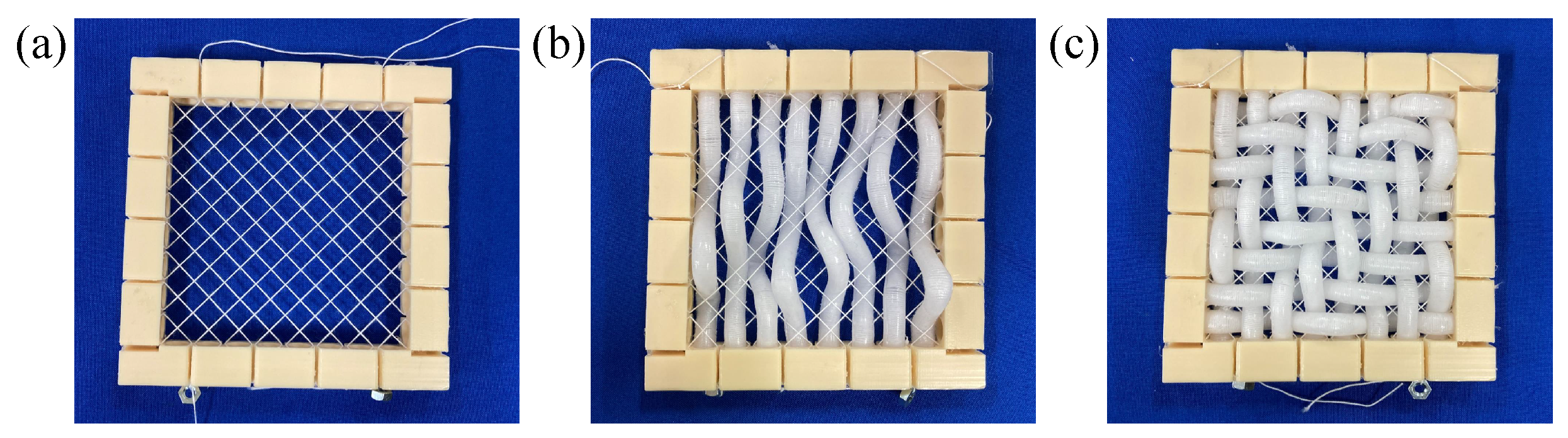
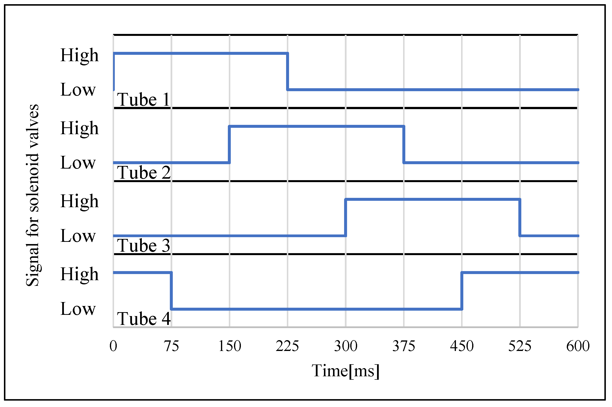
- Diagonally weave threads into the jig as shown in Figure 7a.
- Cut tubes to appropriate lengths. On one side of each tube (approximately 1 cm from the end), seal holes with a well-mixed two-component silicone.
- Weave the tubes on one side of the jig, passing through the threads (Figure 7b). Ensure that the ends with sealed holes from Step 2 are on the same side.
- Weave the tubes into the other side of the jig, passing through the threads from Step 1 and the tubes from Step 3 (Figure 7c). During this process, ensure that the ends of the tubes with sealed holes from Step 2 are on the same side.
- Bond the woven tubes together using silicone.

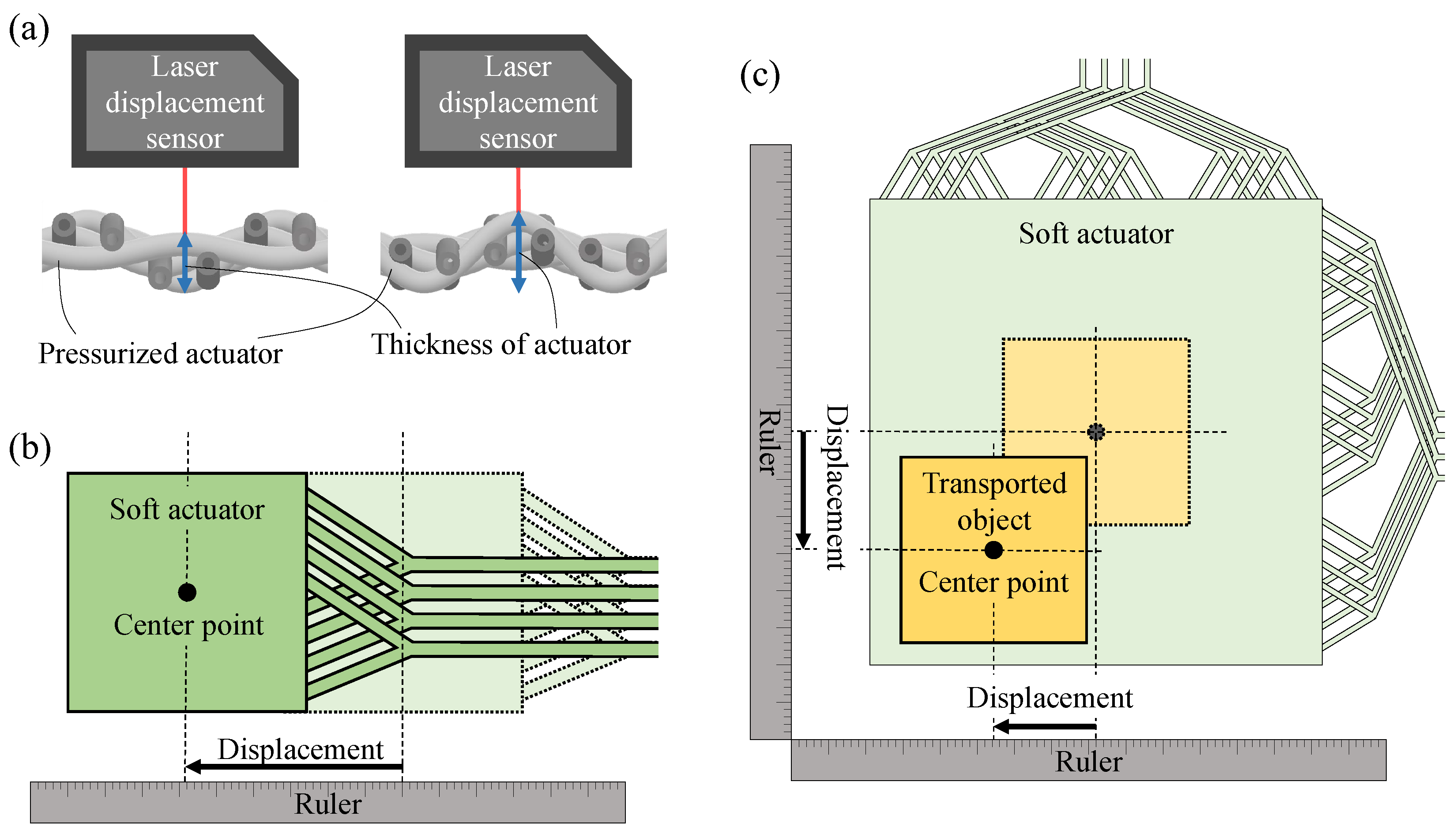
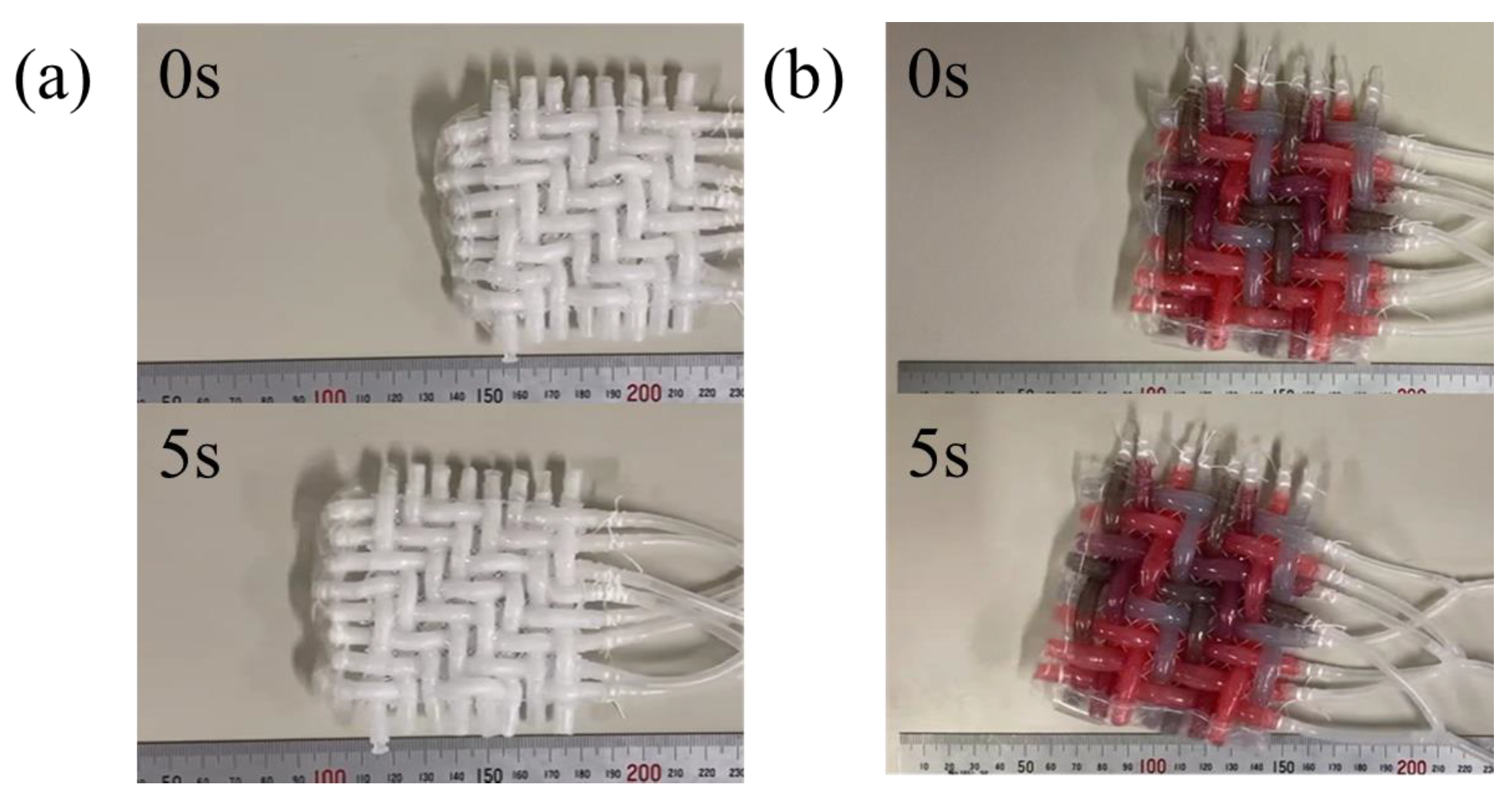
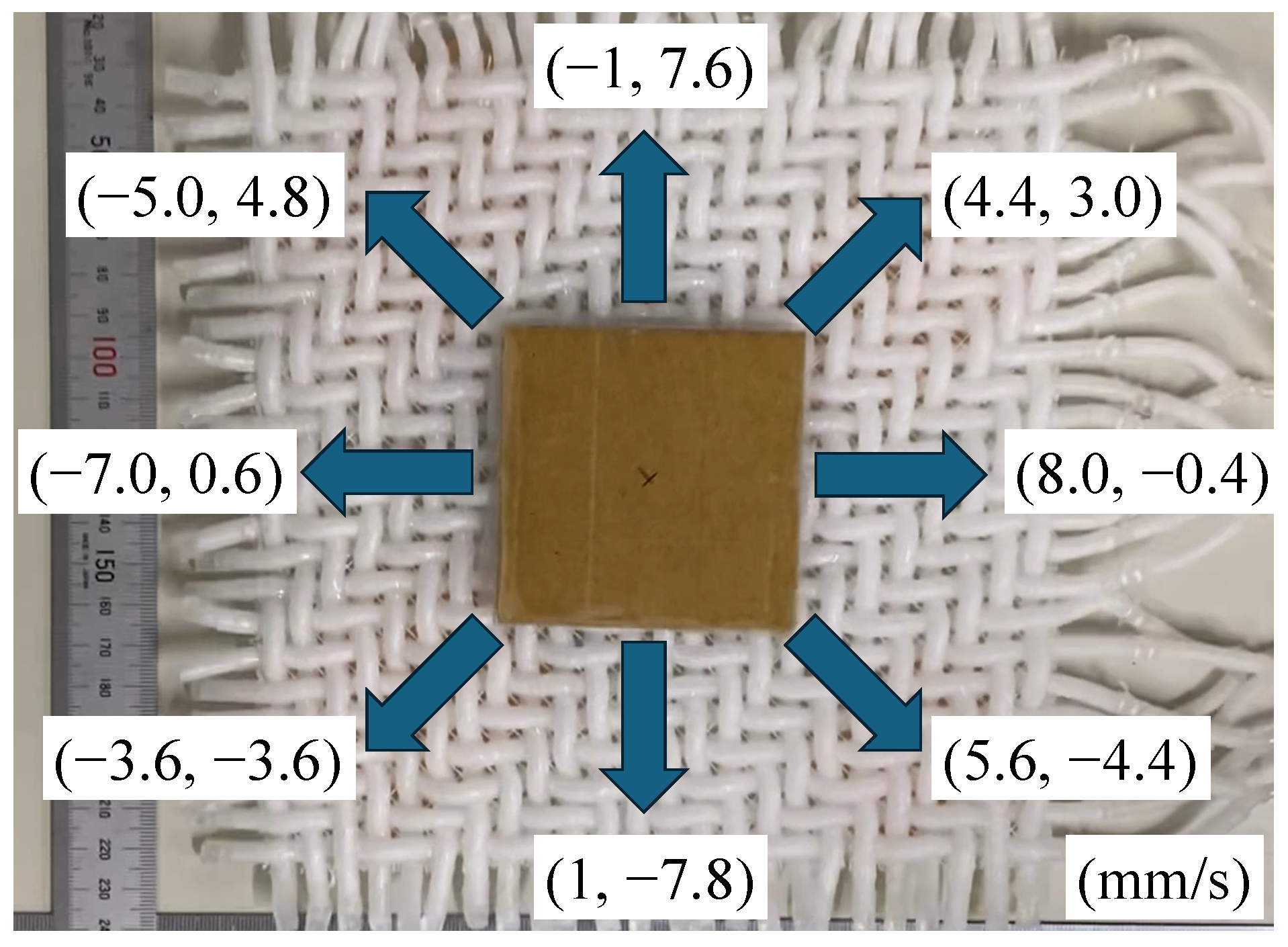
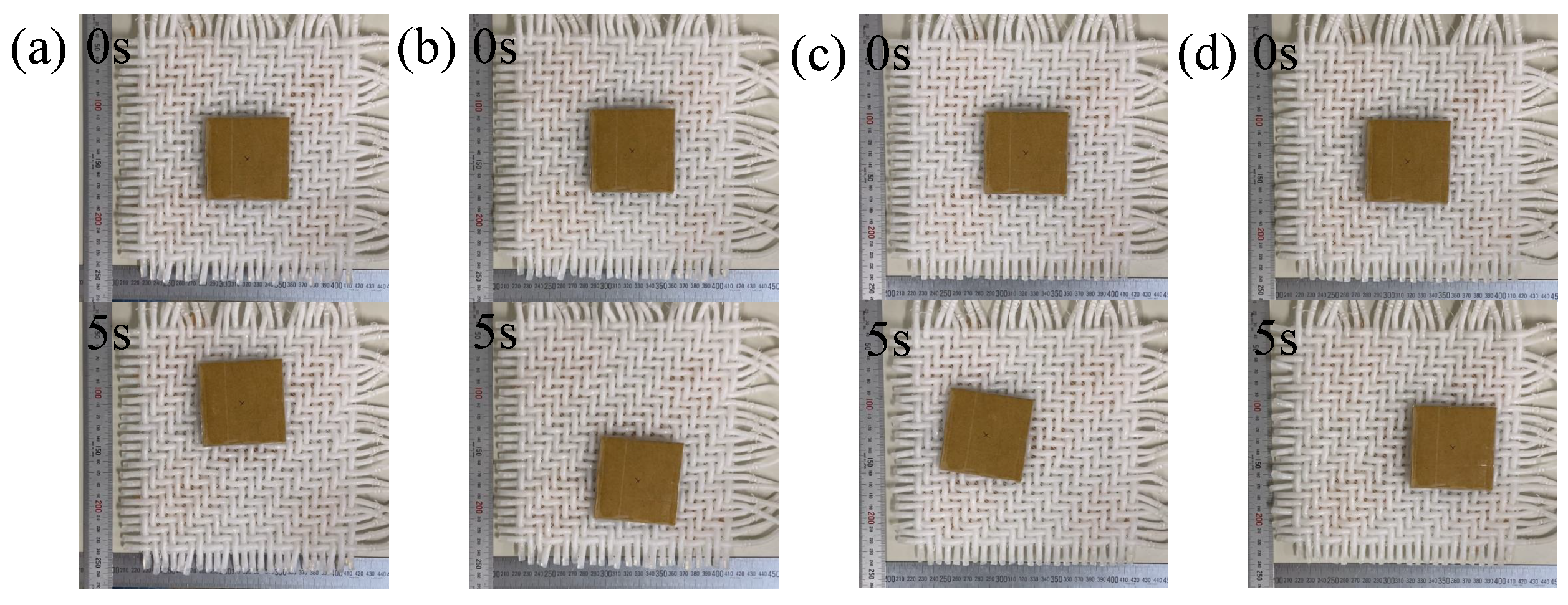
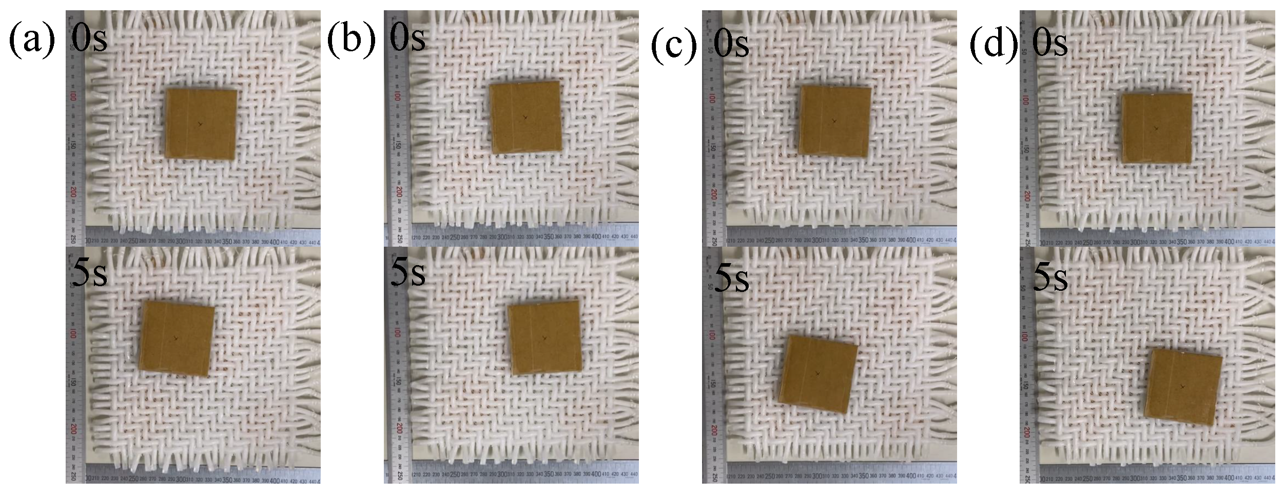
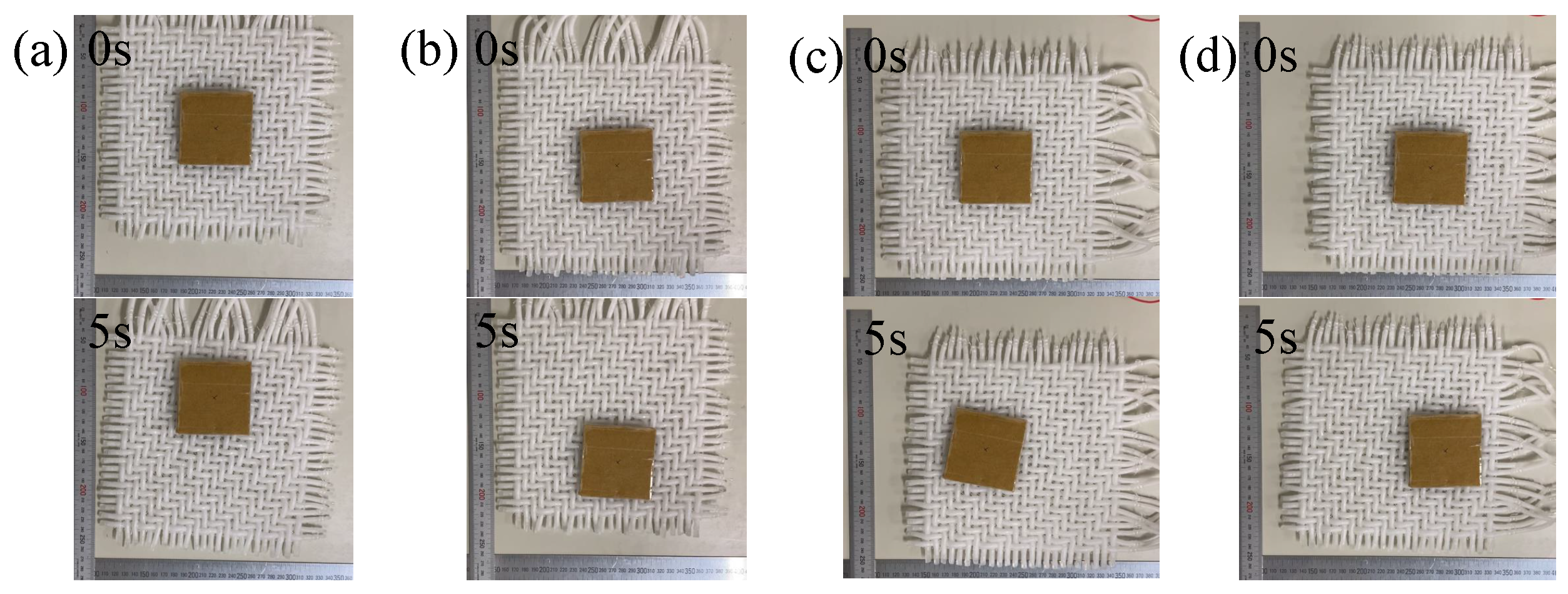
4. Validation
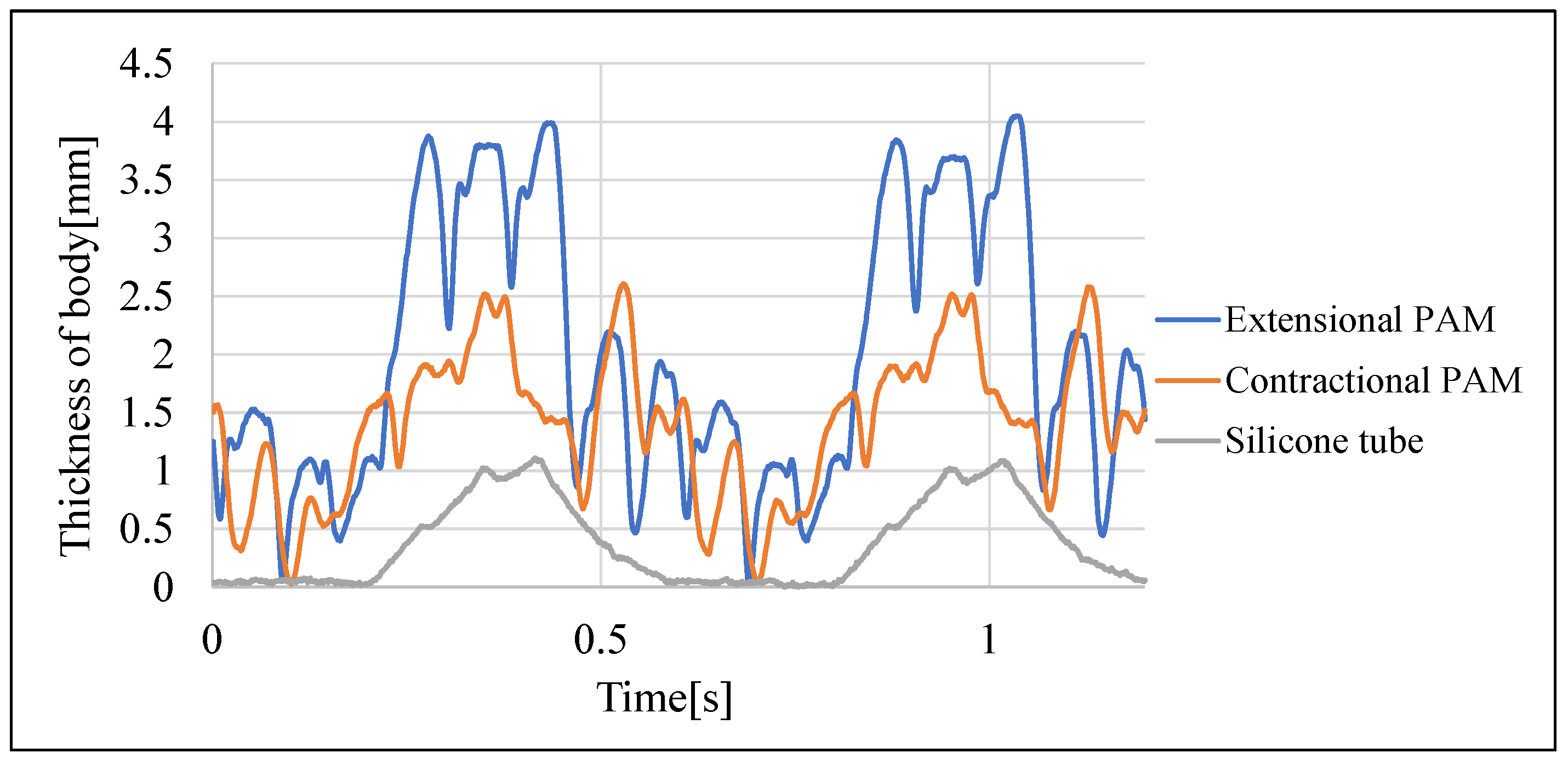
5. Discussion
6. Conclusions
- By periodically pressurizing woven tubes, 2-DOF woven-tube plane-surface soft actuators can be activated.
- The use of extensional PAMs for the actuators was effective in efficiently activating them.
- The actual actuators achieved slower speeds than the theoretical speed because the actual traveling waves in the actuators were discrete, whereas the theoretical speed was calculated under the assumption of continuous traveling waves.
Author Contributions
Funding
Institutional Review Board Statement
Informed Consent Statement
Data Availability Statement
Conflicts of Interest
Abbreviations
| DOF | Degree of Freedom |
| PAM | Pneumatic Artificial Muscle |
References
- Omni Directional Sortation. Available online: https://www.omniawheel.com/conveyor-systems (accessed on 26 October 2023).
- Zaher, W.; Youssef, A.W.; Shihata, L.A.; Azab, E.; Mashaly, M. Omnidirectional-Wheel Conveyor Path Planning and Sorting Using Reinforcement Learning Algorithms. IEEE Access 2022, 10, 27945–27959. [Google Scholar] [CrossRef]
- Abe, K.; Matsui, G.; Tadakuma, K.; Yamano, M.; Tadakuma, R. Development of the omnidirectional transporting table based on omnidirectional driving gear. Adv. Robot. 2020, 34, 358–374. [Google Scholar] [CrossRef]
- Guelpa, V.; Laurent, G.J.; Dahroug, B.; Le Fort-Piat, N. Modular Contact-Free Conveyors for Handling Planar Fragile Objects. IEEE Trans. Robot. 2017, 33, 92–101. [Google Scholar] [CrossRef]
- Chen, X.; Zhong, W.; Li, C.; Fang, J.; Liu, F. Development of a Contactless Air Conveyor System for Transporting and Positioning Planar Objects. Micromachines 2018, 9, 487. [Google Scholar] [CrossRef]
- Zhang, X.; Trakarnchaiyo, C.; Zhang, H.; Khamesee, M.B. MagTable: A tabletop system for 6-DOF large range and completely contactless operation using magnetic levitation. Mechatronics 2021, 77, 102600. [Google Scholar] [CrossRef]
- Liu, Y.; Sun, X.; Zhao, Z.; Zeng, H.; Chen, W. Stability analysis of near-field acoustic levitation considering misalignment and inclination. Int. J. Mech. Sci. 2024, 265, 108901. [Google Scholar] [CrossRef]
- Li, W.; Zhang, P.; Yang, S.; Cai, S.; Feng, K. A novel two-dimensional non-contact platform based on near-field acoustic levitation. Int. J. Mech. Sci. 2024, 265, 108865. [Google Scholar] [CrossRef]
- Trakarnchaiyo, C.; Wang, Y.; Khamesee, M.B. Design of a Compact Planar Magnetic Levitation System with Wrench–Current Decoupling Enhancement. Appl. Sci. 2023, 13, 2370. [Google Scholar] [CrossRef]
- WaveHandling. Available online: https://www.festo.com/us/en/e/about-festo/research-and-development/bionic-learning-network/highlights-from-2013-to-2014/wavehandling-id_33578/ (accessed on 23 November 2023).
- Deng, Z.; Stommel, M.; Xu, W. A Novel Soft Machine Table for Manipulation of Delicate Objects Inspired by Caterpillar Locomotion. IEEE/ASME Trans. Mechatronics 2016, 21, 1702–1710. [Google Scholar] [CrossRef]
- Jang, Y.; Nabae, H.; Endo, G.; Suzumori, K. Analysis of the multi-balloon dielectric elastomer actuator for traveling wave motion. Sensors Actuators Phys. 2022, 333, 113243. [Google Scholar] [CrossRef]
- Watanabe, M.; Tsukagoshi, H. Flexible Sheet Actuator That Generates Bidirectional Traveling Waves. In Proceedings of the 2018 IEEE/ASME International Conference on Advanced Intelligent Mechatronics (AIM), Auckland, New Zealand, 9–12 July 2018; pp. 328–333. [Google Scholar]
- Zhao, T.; Fan, Y.; Lv, J. Photomorphogenesis of Diverse Autonomous Traveling Waves in a Monolithic Soft Artificial Muscle. ACS Appl. Mater. Interfaces 2022, 14, 23839–23849. [Google Scholar] [CrossRef]
- Mansouri, M.; Hsiao-Wecksler, E.T.; Krishnan, G. Toward Design Guidelines for Multidirectional Patient Transfer on a Bed Surface Using Traveling Waves. J. Mech. Robot. 2024, 16, 074501. [Google Scholar] [CrossRef]
- Takeyama, J.; Ichikawa, A.; Hasegawa, A.; Kim, E.; Fukuda, T. A Soft Robot Mimicking snail’s foot. In Proceedings of the 2018 International Symposium on Micro-NanoMechatronics and Human Science (MHS), Nagoya, Japan, 9–12 December 2018; pp. 1–3. [Google Scholar]
- Xin, W.; Pan, F.T.; Li, Y.; Chiu, P.W.Y.; Li, Z. A Novel Biomimic Soft Snail Robot Aiming for Gastrointestinal (GI) Tract Inspection. In Proceedings of the 2020 8th IEEE RAS/EMBS International Conference for Biomedical Robotics and Biomechatronics (BioRob), New York, NY, USA, 29 November–1 December 2020; pp. 1049–1054. [Google Scholar]
- Zhu, R.; Fan, D.; Wu, W.; He, C.; Xu, G.; Dai, J.S.; Wang, H. Soft Robots for Cluttered Environments Based on Origami Anisotropic Stiffness Structure (OASS) Inspired by Desert Iguana. Adv. Intell. Syst. 2023, 5, 2200301. [Google Scholar] [CrossRef]
- Martinez-Sanchez, D.E.; Sandoval-Castro, X.Y.; Cruz-Santos, N.; Castillo-Castaneda, E.; Ruiz-Torres, M.F.; Laribi, M.A. Soft Robot for Inspection Tasks Inspired on Annelids to Obtain Peristaltic Locomotion. Machines 2023, 11, 779. [Google Scholar] [CrossRef]
- Sun, X.; Nose, A.; Kohsaka, H. A vacuum-actuated soft robot inspired by Drosophila larvae to study kinetics of crawling behaviour. PLoS ONE 2023, 18, e0283316. [Google Scholar] [CrossRef]
- Watanabe, M.; Tsukagoshi, H. Soft sheet actuator generating traveling waves inspired by gastropod’s locomotion. In Proceedings of the 2017 IEEE International Conference on Robotics and Automation (ICRA), Singapore, 29 May–3 June 2017; pp. 602–607. [Google Scholar]
- Xu, L.; Chen, H.; Zou, J.; Dong, W.; Gu, G.; Zhu, L.; Zhu, X. Bio-inspired annelid robot: A dielectric elastomer actuated soft robot. Bioinspir. Biomim. 2017, 12, 025003. [Google Scholar] [CrossRef] [PubMed]
- Liu, Z.; Wang, Y.; Wang, J.; Fei, Y. Design and Locomotion Analysis of Modular Soft Robot. Robotica 2022, 40, 3995–4010. [Google Scholar] [CrossRef]
- Zhang, Y.; Yang, D.; Yan, P.; Zhou, P.; Zou, J.; Gu, G. Inchworm Inspired Multimodal Soft Robots with Crawling, Climbing, and Transitioning Locomotion. IEEE Trans. Robot. 2022, 38, 1806–1819. [Google Scholar] [CrossRef]
- Yu, M.; Yang, W.; Yu, Y.; Cheng, X.; Jiao, Z. A Crawling Soft Robot Driven by Pneumatic Foldable Actuators Based on Miura-Ori. Actuators 2020, 9, 26. [Google Scholar] [CrossRef]
- Ge, J.Z.; Calderón, A.A.; Chang, L.; Pérez-Arancibia, N.O. An earthworm-inspired friction-controlled soft robot capable of bidirectional locomotion. Bioinspir. Biomim. 2019, 14, 036004. [Google Scholar] [CrossRef]
- Li, M.; Wang, G.; Wang, J.; Zheng, Y.; Jiao, X. Development of an inchworm-like soft pipe robot for detection. Int. J. Mech. Sci. 2023, 253, 108392. [Google Scholar] [CrossRef]
- Yu, Z.; Peiyu, H.; Bo, Y.; Zhibin, Y.; Dongjie, L.; Guoqi, D. Design and Motion Simulation of a Soft Robot for Crawling in Pipes. Appl. Bionics Biomech. 2023, 2023, 5334604. [Google Scholar] [CrossRef]
- Wan, J.; Sun, L.; Du, T. Design and Applications of Soft Actuators Based on Digital Light Processing (DLP) 3D Printing. IEEE Access 2023, 11, 86227–86242. [Google Scholar] [CrossRef]
- Takayama, T.; Taneda, T. Weaving Method to Avoid Interfere between Inflatable Tubes and Strings for 2D Weaved Tube Plane Surface Soft Actuator. In Proceedings of the 2019 Domestic Conferences of the System Integration (SI) Division, Takamatsu, Japan, 12–14 December 2019; pp. 2888–2889. [Google Scholar]
- Sugano, N. Ultrasonic Motor. J. Horol. Inst. Jpn. 1988, 124, 63–79. [Google Scholar]


| New Prototype 1 | New Prototype 2 | Previous Prototype | |
|---|---|---|---|
| Types of tube used | Extensional PAM | Contractional PAM | Silicone tube |
| Inner diameters of tubes used (mm) | 2.5 | 2.5 | 1.5 |
| Outer diameters of tubes used (mm) | 5 | 6 | 6 |
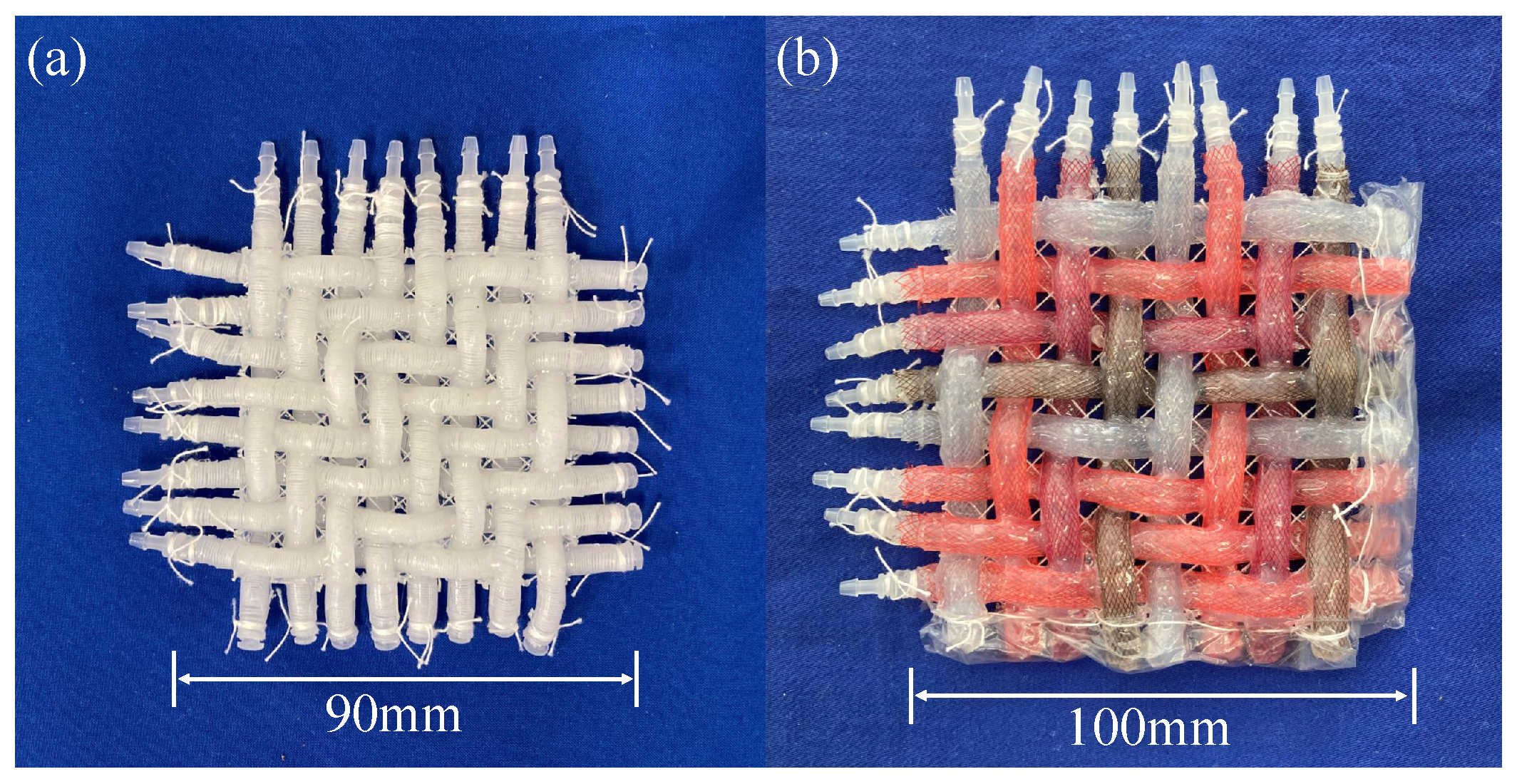
| Numbers of tubes in the prototype | 16 (eight vertical and eight horizontal) | 16 (eight vertical and eight horizontal) | 32 (16 vertical and 16 horizontal) |
| Pitches of tubes in the prototype (mm) | 8 | 10 | 8 |
| Tube lengths in the weaving area (mm) | 70 | 90 | 155 |
| Pressures applied to the prototype (MPa) | 0.2 | 0.2 | 0.15 |
| Transporting Direction | ||||
|---|---|---|---|---|
| Upward | Downward | Leftward | Rightward | |
| (i) Transport velocity of the cardboard relative to the desk (mm/s) | (−0.2, 3.0) | (0.2, −4.6) | (−2.2, 0) | (3.0, 0) |
| (ii) Movement velocity of the body relative to the desk (mm/s) | (0.2, −5.6) | (−0.7, 5.4) | (5.2, −1) | (−5.9, 1) |
| (iii) (i)–(ii) Transport velocity of the cardboard relative to the body (mm/s) | (−0.4, 8.6) | (0.9, −10) | (−7.4, 1) | (8.9, −1) |
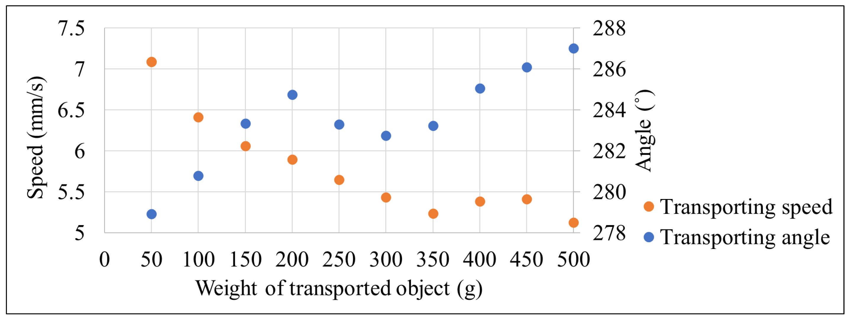
| Weight of Transported Object (g) | ||||||||||
|---|---|---|---|---|---|---|---|---|---|---|
| 50 | 100 | 150 | 200 | 250 | 300 | 350 | 400 | 450 | 500 | |
| Velocity (mm/s) | (1.1, −7.0) | (1.2, −6.3) | (1.4, −5.9) | (1.5, −5.7) | (1.3, −5.5) | (1.2, −5.3) | (1.2, −5.1) | (1.4, −5.2) | (1.5, −5.2) | (1.5, −4.9) |
Disclaimer/Publisher’s Note: The statements, opinions and data contained in all publications are solely those of the individual author(s) and contributor(s) and not of MDPI and/or the editor(s). MDPI and/or the editor(s) disclaim responsibility for any injury to people or property resulting from any ideas, methods, instructions or products referred to in the content. |
© 2024 by the authors. Licensee MDPI, Basel, Switzerland. This article is an open access article distributed under the terms and conditions of the Creative Commons Attribution (CC BY) license (https://creativecommons.org/licenses/by/4.0/).
Share and Cite
Kuriyama, M.; Takayama, T. 2-DOF Woven Tube Plane Surface Soft Actuator Using Extensional Pneumatic Artificial Muscle. Hardware 2024, 2, 50-65. https://doi.org/10.3390/hardware2010003
Kuriyama M, Takayama T. 2-DOF Woven Tube Plane Surface Soft Actuator Using Extensional Pneumatic Artificial Muscle. Hardware. 2024; 2(1):50-65. https://doi.org/10.3390/hardware2010003
Chicago/Turabian StyleKuriyama, Moe, and Toshio Takayama. 2024. "2-DOF Woven Tube Plane Surface Soft Actuator Using Extensional Pneumatic Artificial Muscle" Hardware 2, no. 1: 50-65. https://doi.org/10.3390/hardware2010003