
Active Brazing for Energy Devices Sealing


Abstract
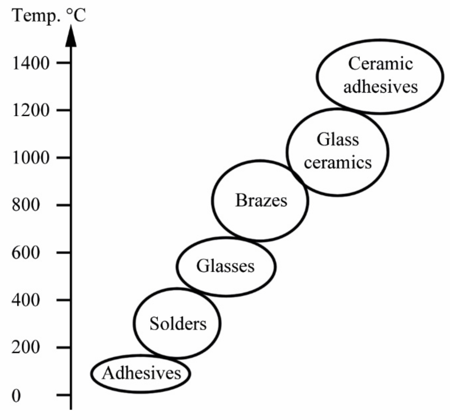
:1. Introduction

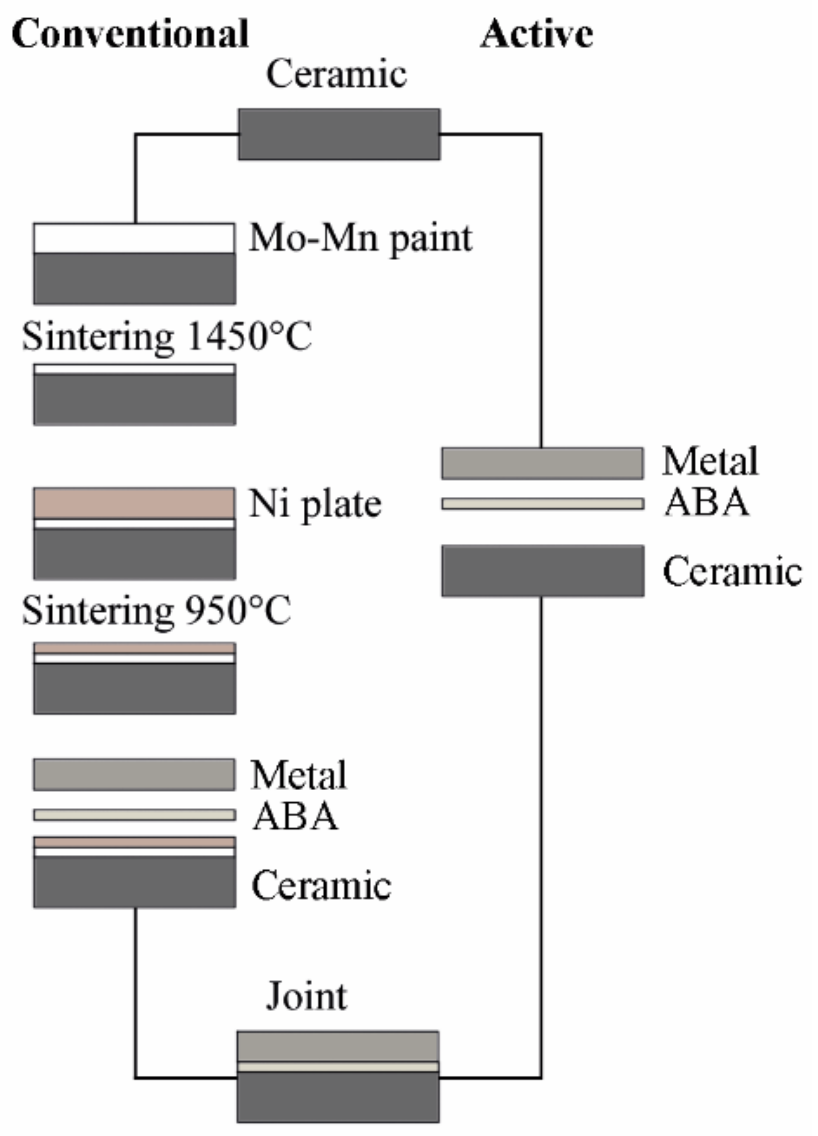
2. Fundamentals of Active Brazing
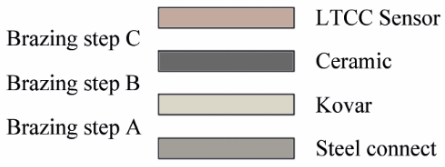
3. Brazement Materials Selection for Water-Vapor Resistant Sensors
3.1. Background
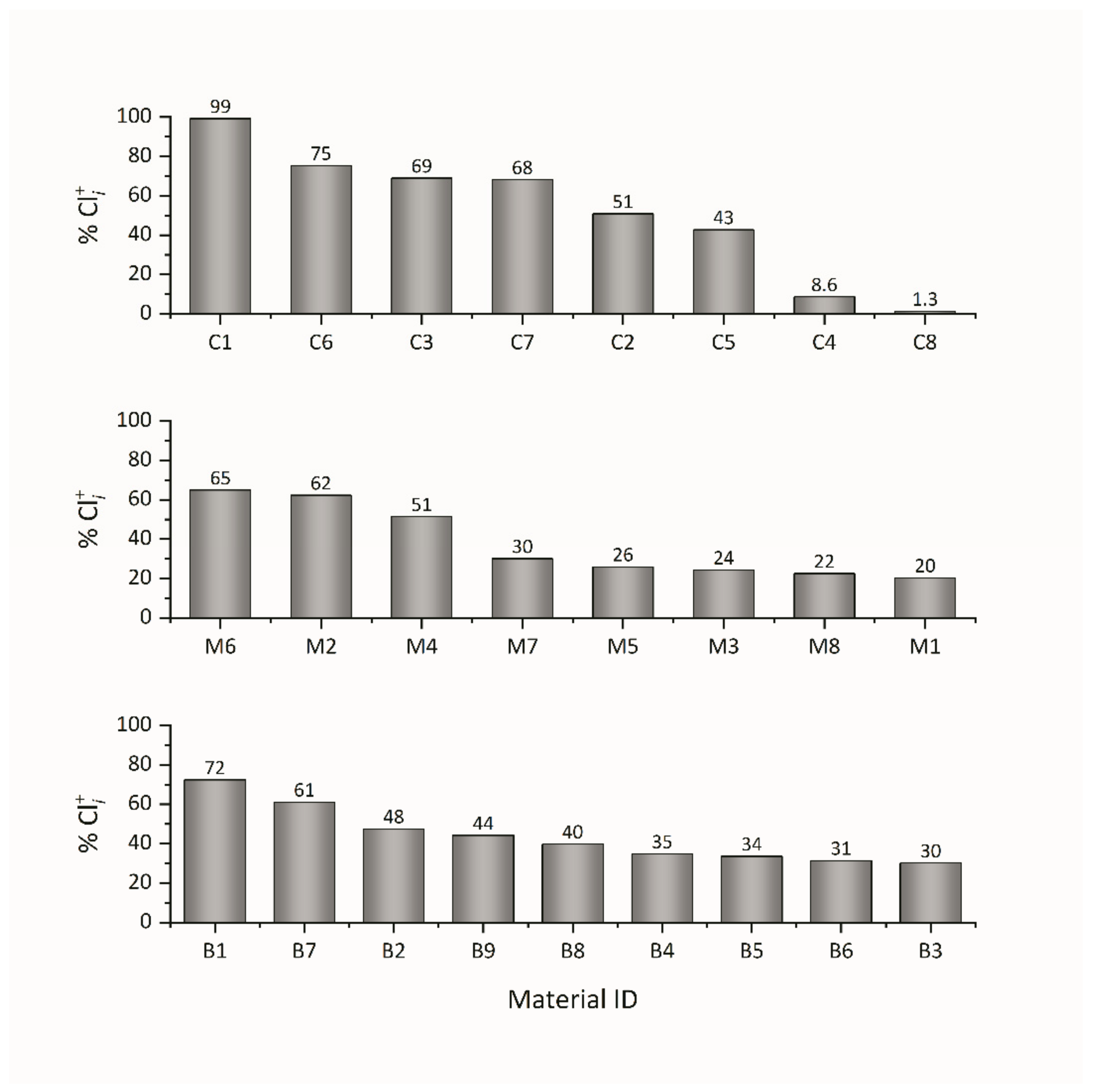
3.2. Multiple Attribute Decision-Making (MADM) Process
3.3. Attributes and Alternatives
3.4. Selected Materials

| CTE 20–500 °C | Young’s Modulus | Shear Modulus | Flexural Strength | Fracture Toughness | Weight Loss Rate a | ||||||||||
|---|---|---|---|---|---|---|---|---|---|---|---|---|---|---|---|
| (ppm/K) | (GPa) | (GPa) | (MPa) | (µg/cm2h) | |||||||||||
| C1 | ZrO2 (98%, 1.9% HfO2, stabilized) | 11.7 | 210 | 81 | 1050 | 6.5 | 0 | ||||||||
| C2 | Yb2SiO5 | 6.3 | 149 | 61 | 215 | 2.3 | 1 | ||||||||
| C3 | Y2SiO5 | 8.3 | 123 | 47 | 100 | 2.2 | 3 | ||||||||
| C4 | Al2TiO5 | 1.6 | 16 | 96 | 40 | 4.0 | 9 | ||||||||
| C5 | Mullite | 5.4 | 151 | 55 | 180 | 2.0 | 11 | ||||||||
| C6 | TiO2 | 9.0 | 228 | 89 | 137 | 3.2 | 22 | ||||||||
| C7 | Al2O3 (99.6%) | 8.2 | 390 | 159 | 470 | 4.0 | 23 | ||||||||
| C8 | SiO2 (99.99%, fused) | 0.7 | 72 | 31 | 104 | 1.1 | 100 | ||||||||
| Ratio b Yield Strength | Ratio b UTS | Ratio b Reduction in Area | Ratio b Elongation | Uniform Corr. | Pitting/ Crevice | Erosion | Sulfide Attack | SICC c | Impingement | Water Quality d | Cost e | ||||
| - | - | - | - | - | - | - | - | - | - | - | - | ||||
| M1 | 304 | 18 | 200 | 1.11 | 0.89 | 0.41 | 0.65 | 1 | 2 | 1 | 1 | 1 | 1 | F | 6 |
| M2 | 316Ti | 19 | 200 | 1.00 | 1.06 | 0.99 | 1.06 | 1 | 2 | 1 | 1 | 1 | 1 | F | 6.5 |
| M3 | 318LN | 15 | 200 | 0.97 | 0.89 | 0.46 | 0.63 | 1 | 2 | 1 | 1 | 1 | 1 | F | 10 |
| M4 | Titanium G2 | 9.7 | 107 | 1.03 | 0.82 | 0.56 | 0.60 | 1 | 1 | 1 | 1 | 1 | 1 | F/B/S | 36 |
| M5 | Sea-Cure | 11 | 217 | 1.05 | 0.89 | 0.50 | 0.55 | 1 | 1 | 1 | 1 | 1 | 1 | F/B/S | 11 |
| M6 | AL-6X | 16 | 195 | 1.02 | 0.97 | 1.02 | 1.02 | 1 | 1 | 1 | 1 | 1 | 1 | F/B/S | 17 |
| M7 | AL-29-4C | 10.8 | 207 | 1.09 | 0.81 | 0.55 | 0.58 | 1 | 1 | 1 | 1 | 1 | 1 | F/B/S | 12 |
| M8 | Inconel 718 | 14.4 | 170 | 0.99 | 0.91 | 0.32 | 0.45 | 2 | 2 | 1 | 4 | 2 | 2 | F/B/S | 100 |
| Liquidus Temp. | Solidus Temp. | Yield Strength | UTS | ||||||||||||
| (°C) | (°C) | (MPa) | (MPa) | ||||||||||||
| B1 | CB2 | 22 | 71 | 970 | 970 | 60 | 130 | ||||||||
| B2 | CB4 | 19 | 80 | 805 | 780 | 230 | 271 | ||||||||
| B3 | Ticusil | 19 | 85 | 900 | 780 | 292 | 339 | ||||||||
| B4 | Cusil–ABA | 19 | 83 | 815 | 780 | 271 | 346 | ||||||||
| B5 | Cusin-1 ABA | 19 | 83 | 806 | 775 | 260 | 402 | ||||||||
| B6 | Incusil–ABA | 18 | 76 | 715 | 605 | 338 | 455 | ||||||||
| B7 | Silver–ABA | 21 | 77 | 912 | 860 | 136 | 282 | ||||||||
| B8 | Gold–ABA | 16 | 87 | 1030 | 1003 | 209 | 334 | ||||||||
| B9 | Au–4Ti | 14 | 82 | 1064 | 1063 | 195 | 310 |
| ABA | Composition | Melting Range | Metal | Strength | Test Type | Geometry | Braze Thickness | Brazing Temp. | Brazing Duration | Atm. | Atm. Pressure | Laser Power | Ref. |
|---|---|---|---|---|---|---|---|---|---|---|---|---|---|
| - | - | (°C) | - | (MPa) | - | - | (µm) | (°C) | (ks) | - | (Pa) | (W) | - |
| Cusil–ABA | Ag35.25Cu1.75Ti | 780–815 | 304 | 88 ± 8 | Shear | Rectangular lap | 50 | 830 | 0.6 | HV | 1 × 10⁻⁵ | [40] | |
| Cusin-1 ABA | (Ag35Cu)97Ti2Sn1 | 775–806 | 304 | 89.8 ± 4 | Shear | Double lap | 30–40 | 800–850 | 0.6 | HV | [41] | ||
| Cusin-1 ABA | (Ag35Cu)97Ti2Sn1 | 775–806 | 304 | 21.9 ± 0.6 | Tensile | Disc/bar tee | 30–40 | 800–850 | 0.6 | HV | [41] | ||
| m-BAg-8 | (Ag28Cu)100-xTix | 304 | 63 | Tensile | Tubular butt | 100 | 900 | 0.6 | HV | 1 × 10⁻³ | [42] | ||
| m-BAg-8 | (Ag28Cu)94Ti6-W | 304 | 13.2 | Tensile | Single lap | 50 | 900 | 1.8 | HV | 3 × 10⁻⁴ | [43] | ||
| Cusil–ABA | Ag35.25Cu1.75Ti | 780–815 | 304 | 13.5 | Tensile | Single lap | 50 | 900 | 1.8 | HV | 3 × 10⁻⁴ | [43] | |
| CB4 | (Ag27.3Cu)97Ti3 | 780–805 | 304 | Rectangular lap | 100 | Ar | 144 | [44] | |||||
| Zrcusil | Ag1Cu2Zr | 304L | 114 | Tensile | ASTM F19 | 985 | 0.3 | UHV | [21] | ||||
| m-BAg-8 | (Ag28Cu)97Ti3 | 780–805 | 321 | 18.4 | Shear | Disc butt | 50 | 850 | 0.6 | HV | 5 × 10⁻³ | [45] | |
| Ticusil | (Ag28Cu)95.5Ti4.5 | 780–900 | 630 | 170 | Shear | Rectangular lap | 100 | 880 | 0.6 | HV | 6 × 10⁻³ | [46] | |
| Incusil–ABA | Ag27.2Cu12.5In1.25Ti | 605–715 | A108 | 42 | Shear | Tubular butt | 200 | 950 | 0.12–0.18 | Ar | 320 | [47] | |
| CB4 | (Ag27.3Cu)97Ti3 | 780–805 | 100Cr6/C45E | 82 | Bending | Butt | 50 | Ar | 300–360 | [48] | |||
| Cusil–ABA | Ag35.25Cu1.75Ti | 780–815 | Kovar | 97 | Tensile | ASTM F19 | 825 | 0.12 | Ar | [21] | |||
| m-BAg-8 | (Ag28Cu)92Ti8 | Kovar | 78 | Tensile | ASTM F19 | 890 | 0.3 | HV | 3 × 10⁻³ | [49] | |||
| Cusil–ABA | Ag35.25Cu1.75Ti | 780–815 | Kovar | 60 ± 15 | Tensile | ASTM F19 | 50 | 844 | 0.12 | V | 4 × 10⁻¹ | [50] | |
| Ticusil | (Ag28Cu)95.5Ti4.5 | 780–900 | Kovar | 67 ± 4 | Shear | Rectangular lap | 100 | 850 | 0.6 | HV | 1 × 10⁻³ | [51] | |
| Cusil–ABA (outdated) | (Ag28Cu)98Ti2 | Kovar | 29 ± 13 | Shear | Rectangular lap | 100 | 840 | 0.6 | HV | 7 × 10⁻² | [52] | ||
| m-BAg-8 | (Ag28Cu)98(TiH2)2 | TiAl | 102 | Shear | Rectangular lap | 100–150 | 880 | 0.6 | HV | 3 × 10⁻⁴ | [53] |
| ABA | Ceramic | Metal | RT Strength | Test Type | Geometry | Braze Thickness | Brazing Temp. | Brazing Duration | Atm. | Atm. Pressure | Load | Ref. |
|---|---|---|---|---|---|---|---|---|---|---|---|---|
| - | - | - | (MPa) | - | - | (µm) | (°C) | (ks) | - | (Pa) | (MPa) | - |
| Ticusil | 3YSZ | Ferritic SS | 40 ± 8 | Shear | Rectangular lap | 100–120 | 915 | 0.3 | HV | 1 × 10⁻⁴ | [54] | |
| Ticusil | 8YSZ | 1.4755 | Rectangular lap | 50 | 900 | 0.6 | HV | 5 × 10⁻³ | [55] | |||
| Ag0.5Al Ag8Cu Ag8Cu0.5Ti | 3YSZ 8YSZ Al2O3 | 1.4760 | Rectangular lap | 970–1150 | 1.2 | Air | [56] | |||||
| Ag0.5Al Ag4Cu Ag8Cu | 3YSZ | 1.4755 (Crofer22H) | Rectangular lap | 100 | 1000 | 0.6 | Air | 1.5 | [9] | |||
| Ag28Cu + TiH2 | 3YSZ | 1.4301 (304) | <∼90 | Shear | Disc/bar | 820–860 | 0.6–3 | HV | 7 × 10⁻³ | [57] | ||
| Ag4CuO | Al2O3 (99.6%) | 1.4760 (Crofer22APU) | ≤115 ± 10 | Shear | Rectangular lap | 76 | 1000–1100 | 0.3 | Air | [58] | ||
| Ag8CuO | 8YSZ | 1.4760 | ≤21.3 at 550 °C | Shear | Rectangular butt | 100 | Air | [59] | ||||
| Ag4CuO | 3YSZ | Aluminized 1.4755 | ≤44.3 | Rectangular lap | ∼200 | 950–1100 | 1.8 | Air | [60] | |||
| Ag2CuO | CGO | Aluminized 1.4755 | 39 ± 3 | Shear | Rectangular butt | 100 | 1000 | 1.2 | Air | 0.1 | [61] | |
| Ag8CuO | YSZ | Coated 1.4760 | 55 ± 3 | Shear | Rectangular lap | ∼150 | 1050 | 1.8 | Air | 1 × 10⁻³ | [62] | |
| AgxCuO | YSZ | 1.4016 (430) | Disc/bar | ∼700 | 950 | 1.8 | Air | [63] | ||||
| Ag–CuO–TiO2 | LSCoF | Fecralloy | 950–1100 | 1.8 | Air | [64] | ||||||
| AgxCuAlO2 | 3YSZ | 1.4845 (310S) | Air | 4.7 × 10⁻³ | [65] | |||||||
| AgxAl2TiO5 | YSZ | 1.4760 | Rectangular lap | ∼29 | 920–950 | 1.2 | Air | [66] | ||||
| Ticusil–Al2TiO5/TiH2 | 8YSZ | 1.4016 | <500 | 880 | 0.3 | [36] | ||||||
| AgxV2O5 | LSCoF | 26 ± 9 | Bending | Rectangular butt | 1000/1100 | 1.8 | Air | [67] | ||||
| Ag5Nb2O5 | YSZ | 1.4845 (310S) | <110 | Shear | Rectangular lap | <250 | 1150 | 1.8 | Air | [68] | ||
| AgxSiO2 | 8YSZ | ≤47 | Shear | Rectangular lap | 1050 | 1.8 | Air | 2 | [69] |
4. Solutions to Energy Devices Sealing
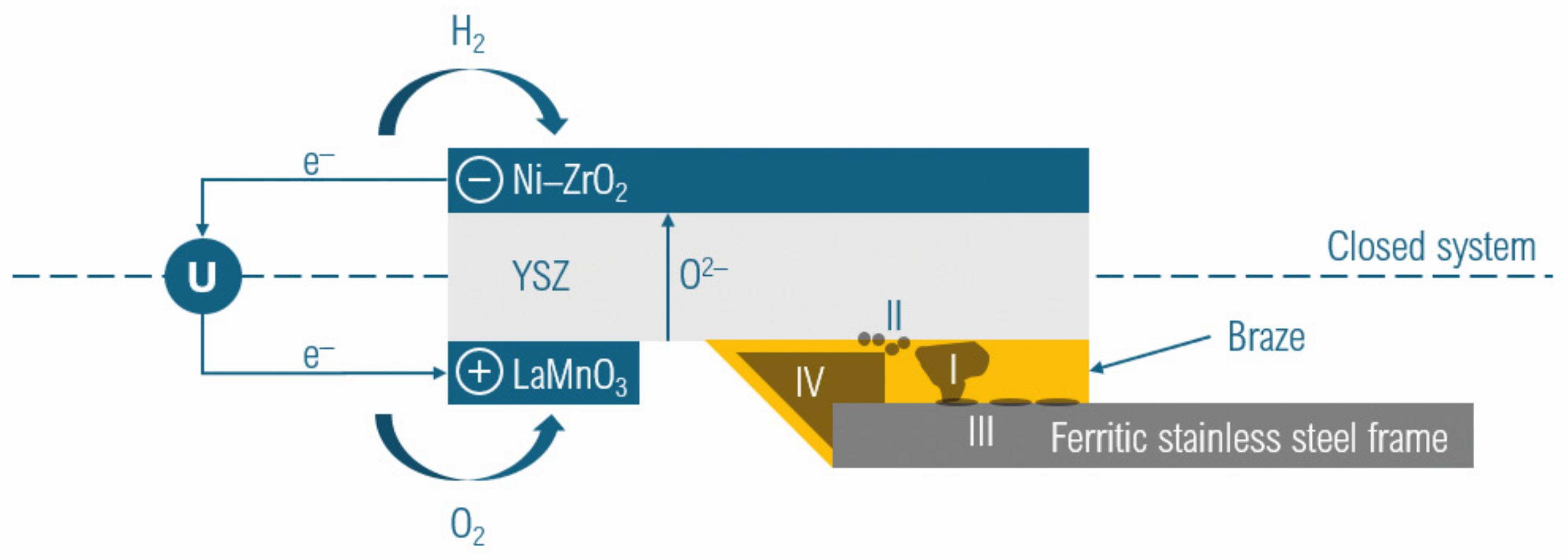
4.1. Nuclear Reactors
4.2. Nuclear Safety Sensors
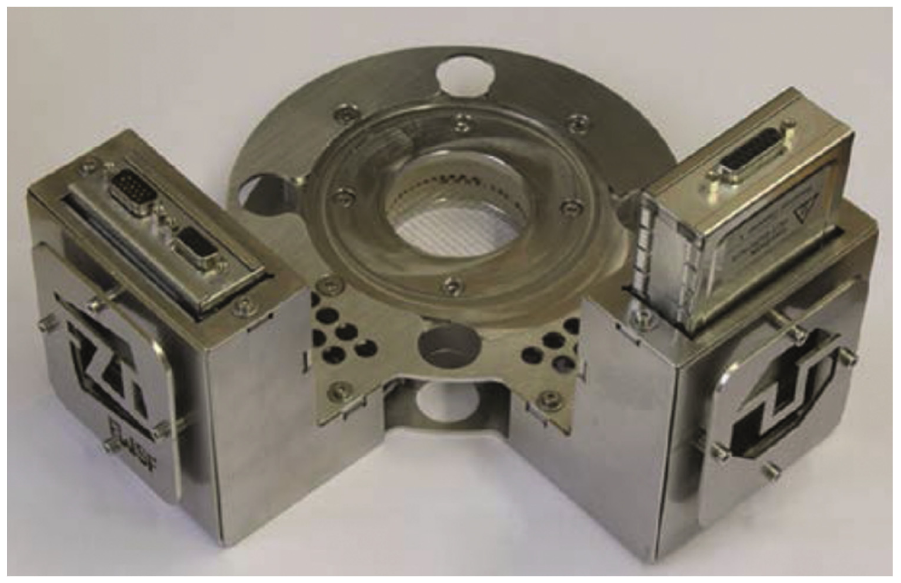
4.2.1. Wire-Mesh Multi-Flow Sensors
4.2.2. Fiber Sensors
4.3. Hydrogen Devices
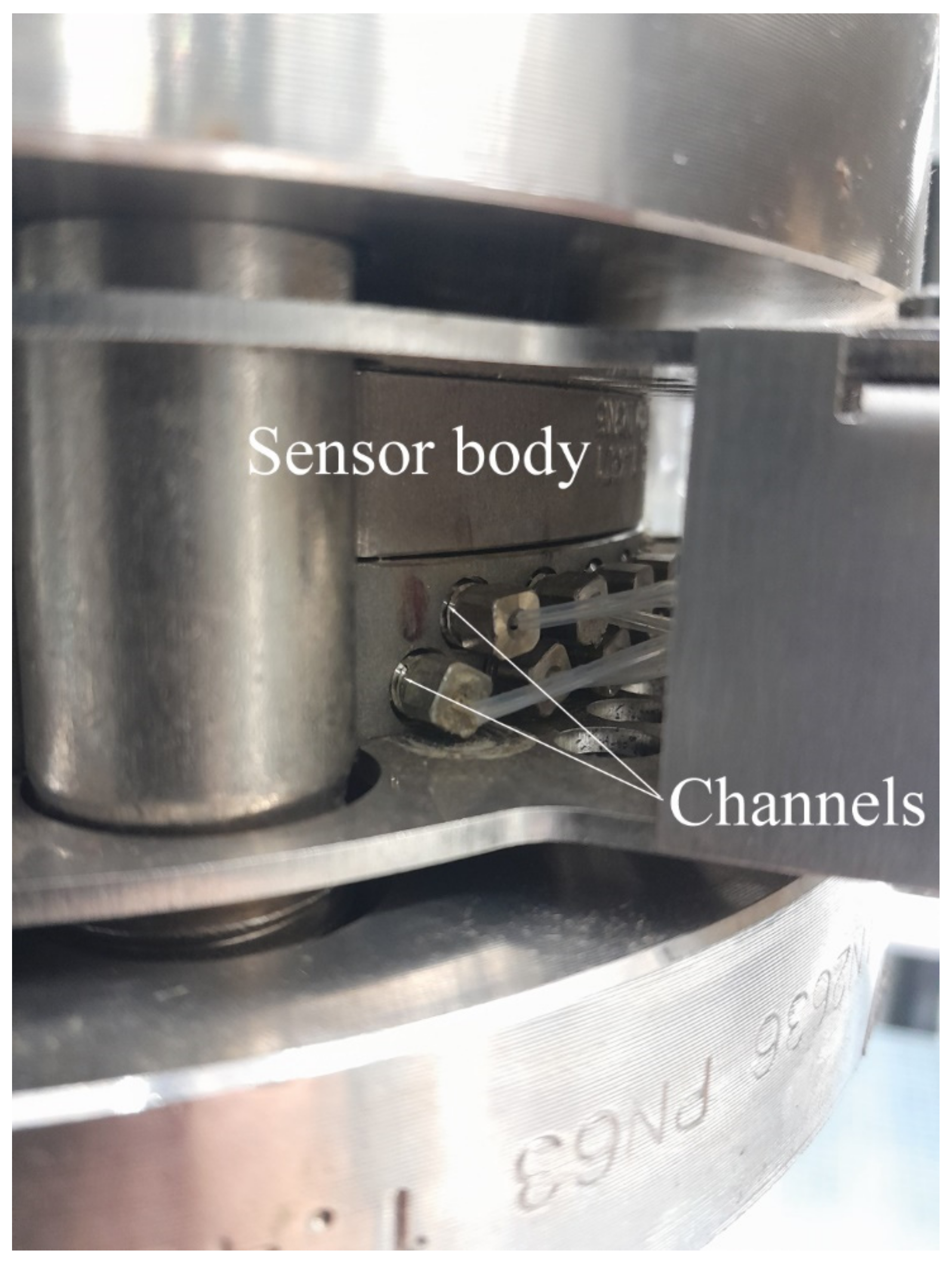
4.3.1. Ceramic-Based Pressure Sensors
4.3.2. SOEC/SOFC
4.4. Thermoelectric Generators (TEGs)
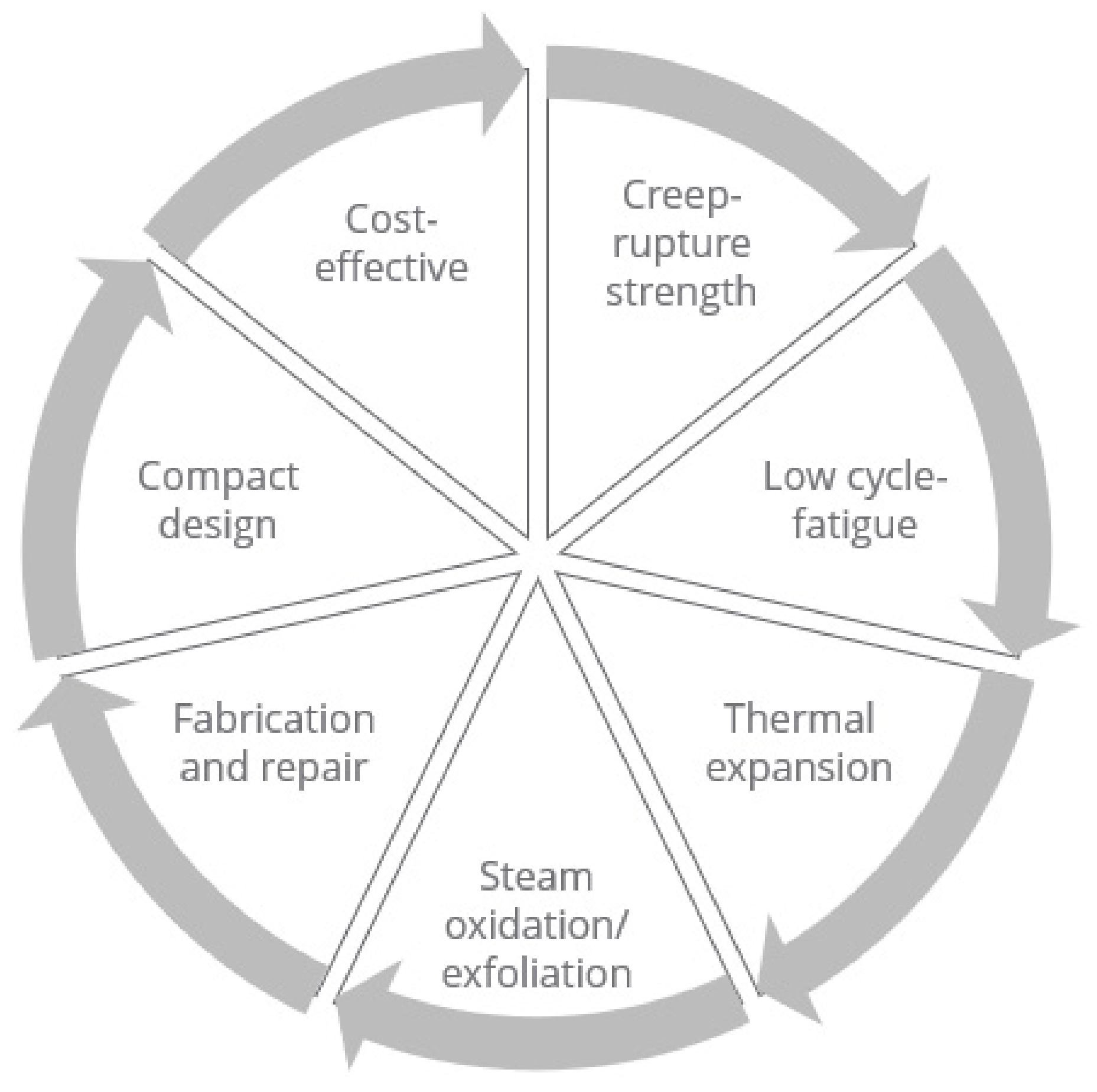
5. Brazement Degradation
5.1. Design Aspects
5.2. Transport Aspects
5.3. Thermal Cycles Aspects
6. Closing Remarks
Author Contributions
Funding
Data Availability Statement
Conflicts of Interest
References
- Weber, F. Konflikte um Die Energiewende; Springer: Wiesbaden, Germany, 2018. (In German) [Google Scholar]
- Elssner, G.; Petzow, G. Metal/Ceramic Joining. ISIJ Int. 1990, 30, 1011–1032. [Google Scholar] [CrossRef]
- Elssner, G.; Petzow, G. Verträglichkeit zwischen Materialkomponenten ın Metall-Keramik-Verbundwerkstoffen. Int. J. Mater. Res. 1973, 64, 280–286. (In German) [Google Scholar] [CrossRef]
- Wang, G.; Lannutti, J.J. Chemical thermodynamics as a predictive tool in the reactive metal brazing of ceramics. Metall. Mater. Trans. A 1995, 26, 1499–1505. [Google Scholar] [CrossRef]
- Mishra, S.; Sharma, A.; Jung, D.H.; Jung, J.P. Recent Advances in Active Metal Brazing of Ceramics and Process. Met. Mater. Int. 2020, 26, 1087–1098. [Google Scholar] [CrossRef]
- Peteves, S.D.; Paulasto, M.; Ceccone, G.; Stamos, V. The reactive route to ceramic joining: Fabrication, interfacial chemistry and joint properties. Acta Mater. 1998, 46, 2407–2414. [Google Scholar] [CrossRef]
- Weil, K.S.; Coyle, C.A.; Darsell, J.T.; Xia, G.G.; Hardy, J.S. Effects of thermal cycling and thermal aging on the hermeticity and strength of silver–copper oxide air-brazed seals. J. Power Sources 2005, 152, 97–104. [Google Scholar] [CrossRef]
- Waetzig, K.; Schilm, J.; Mosch, S.; Tillmann, W.; Eilers, A.; Wojarski, L. Influence of the Brazing Paste Composition on the Wetting Behavior of Reactive Air Brazed Metal–Ceramic Joints. Adv. Eng. Mater. 2021, 23, 2000711. [Google Scholar] [CrossRef]
- Li, C.C.; Kuhn, B.; Brandenberg, J.; Beck, T.; Singheiser, L.; Bobzin, K.; Bagcivan, N.; Kopp, N. Improving Contour Accuracy and Strength of Reactive Air Brazed (RAB) Ceramic/Metal Joints by Controlling Interface Microstructure. Adv. Eng. Mater. 2012, 14, 394–399. [Google Scholar] [CrossRef]
- Akselsen, O.M. Advances in brazing of ceramics. J. Mater. Sci. 1992, 27, 1989–2000. [Google Scholar] [CrossRef]
- Walker, C.A.; Hodges, V.C. Comparing metal-ceramic brazing methods. Weld. J. 2008, 87, 43–50. [Google Scholar]
- Passerone, A.; Muolo, M.L. Joining Technology in Metal-Ceramic Systems. Mater. Manuf. Process. 2000, 15, 631–648. [Google Scholar] [CrossRef]
- Fernie, J.A.; Drew, R.A.L.; Knowles, K.M. Joining of engineering ceramics. Int. Mater. Rev. 2009, 54, 283–331. [Google Scholar] [CrossRef]
- Sivaprahasam, D.; Sujitha, T.; Gowtham, U.; Jayachandran, B.; Gopalan, R. Microstructure and heat transfer characteristics of active brazed Ceramic–Metal joints. Ceram. Int. 2021, 47, 16133–16140. [Google Scholar] [CrossRef]
- Kassam, T.A. A Review of the Alumina/Ag-Cu-Ti Active Metal Brazing Process; CRC Press: Boca Raton, FL, USA, 2018; p. 256. [Google Scholar]
- Asthana, R.; Singh, M. 11—Active metal brazing of advanced ceramic composites to metallic systems. In Advances in Brazing; Sekulić, D.P., Ed.; Woodhead Publishing: Sawston, UK, 2013; pp. 323–360. [Google Scholar]
- Weil, K.S. The state-of-the-art in sealing technology for solid oxide fuel cells. JOM 2006, 58, 37–44. [Google Scholar] [CrossRef]
- Schilm, J.; Rost, A.; Poenicke, A.; Kusnezoff, M.; Michaelis, A. Ceramic Integration Technologies for Solid Oxide Fuel Cells. Int. J. Appl. Ceram. Technol. 2012, 9, 688–699. [Google Scholar] [CrossRef]
- Fernie, J.A.; Hanson, W.B. Best practice for producing ceramic-metal bonds. Ind. Ceram. 1999, 19, 172–175. (In Italian) [Google Scholar]
- Walker, C.A.; Bishop, G.; De Smet, D.J. Single and Double Reaction Layer Formation Using Reduced Active Element Containing Brazing Filler Metals; Sandia National Lab (SNL-NM): Albuquerque, NM, USA, 2015. [Google Scholar]
- Walker, C.A. 16—Metal–nonmetal brazing for electrical, packaging and structural applications. In Advances in Brazing; Sekulić, D.P., Ed.; Woodhead Publishing: Sawston, UK, 2013; pp. 498–524. [Google Scholar]
- Lugscheider, E.; Tillmann, W. Development of new active filler metals in a Ag-Cu-Hf system. Weld. J. Res. Suppl. 1990, 69, 416–421. [Google Scholar]
- Bellosi, A.; Kosmac, T.; Tomsia, A.P. Interfacial Science in Ceramic Joining; Springer Science & Business Media: Dordrecht, The Netherlands, 1998; Volume 58. [Google Scholar]
- Bobzin, K.; Kopp, N.; Wiesner, S. Influence of Filler and Base Material on the Pore Development during Reactive Air Brazing. Adv. Eng. Mater. 2014, 16, 1456–1461. [Google Scholar] [CrossRef]
- Pönicke, A.; Schilm, J.; Kusnezoff, M.; Michaelis, A. Aging Behavior of Reactive Air Brazed Seals for SOFC. Fuel Cells 2015, 15, 735–741. [Google Scholar] [CrossRef]
- Kim, J.Y.; Hardy, J.S.; Weil, K.S. Effects of CuO Content on the Wetting Behavior and Mechanical Properties of a Ag–CuO Braze for Ceramic Joining. J. Am. Ceram. Soc. 2005, 88, 2521–2527. [Google Scholar] [CrossRef]
- Pietruske, H.; Prasser, H.M. Wire-mesh sensors for high-resolving two-phase flow studies at high pressures and temperatures. Flow Meas. Instrum. 2007, 18, 87–94. [Google Scholar] [CrossRef]
- Hampel, U.; Otahal, J.; Boden, S.; Beyer, M.; Schleicher, E.; Zimmermann, W.; Jicha, M. Miniature conductivity wire-mesh sensor for gas-liquid two-phase flow measurement. Flow Meas. Instrum. 2009, 20, 15–21. [Google Scholar] [CrossRef]
- Lucas, D.; Beyer, M.; Krepper, E. TOPFLOW-Experiments, Development and Validation of CFD Models for Steam-Water Flows with Phase Transfer. Final Report; TOPFLOW-Experimente, Modellentwicklung und Validierung von CFD-Codes fuer Wasser-Dampf-Stroemungen mit Phasenuebergang. Abschlussbericht; Helmholtz-Zentrum Dresden-Rossendorf Institut für Sicherheitsforschung: Dresden, Germany, 2011. (In German) [Google Scholar]
- Hosemann, P.; Frazer, D.; Fratoni, M.; Bolind, A.; Ashby, M.F. Materials selection for nuclear applications: Challenges and opportunities. Scr. Mater. 2018, 143, 181–187. [Google Scholar] [CrossRef]
- Hwang, C.L.; Yoon, K.S. Multiple Attribute Decision Making Methods and Applications: A State-of-the-Art Survey; Springer: Berlin/Heidelberg, Germany, 1981; p. 269. [Google Scholar]
- Klemm, H.; Fritsch, M.; Schenk, B. Corrosion of Ceramic Materials in Hot Gas Environment. In 28th International Conference on Advanced Ceramics and Composites B: Ceramic Engineering and Science Proceedings; Lara-Curzio, E., Readey, M.J., Eds.; The American Ceramics Society: Columbus, OH, USA, 2004; Volume 25, pp. 463–468. [Google Scholar]
- Opila, E.J.; Jacobson, N.S.; Myers, D.L.; Copland, E.H. Predicting oxide stability in high-temperature water vapor. JOM 2006, 58, 22–28. [Google Scholar] [CrossRef]
- Ueno, S.; Jayaseelan, D.D.; Ohji, T. Development of Oxide-Based EBC for Silicon Nitride. Int. J. Appl. Ceram. Technol. 2004, 1, 362–373. [Google Scholar] [CrossRef]
- Louthan, M.R.; Caskey, G.R.; Donovan, J.A.; Rawl, D.E. Hydrogen embrittlement of metals. Mater. Sci. Eng. 1972, 10, 357–368. [Google Scholar] [CrossRef]
- Tucker, M.C.; Jacobson, C.P.; De Jonghe, L.C.; Visco, S.J. A braze system for sealing metal-supported solid oxide fuel cells. J. Power Sources 2006, 160, 1049–1057. [Google Scholar] [CrossRef]
- Kobsiriphat, W.; Barnett, S. Ag–Cu–Ti Braze Materials for Sealing SOFCs. J. Fuel Cell Sci. Technol. 2008, 5, 011002. [Google Scholar] [CrossRef]
- Schaefer, R.P.; Flynn, J.E.; Doyle, J.R. Brazing filler metal evaluation for an aircraft gas turbine engine application. Weld. J. 1971, 50, 394s–400s. [Google Scholar]
- Xian, A.P.; Si, Z.Y.; Zhou, L.J.; Shen, J.N.; Li, T.F. An improvement of the oxidation resistance of Ag-Cu eutectic-5 at% Ti brazing alloy for metal/ceramic joints. Mater. Lett. 1991, 12, 84–88. [Google Scholar] [CrossRef]
- Beeranur, R.; Waghmare, K.K.; Singh, R.k. Characterization of Vacuum Brazing of SS 304 and Alumina Ceramic with Active Brazing Alloy. Procedia Mater. Sci. 2014, 5, 969–977. [Google Scholar] [CrossRef]
- Zhu, M.G.; Chung, D.D.L. Improving the strength of brazed joints to alumina by adding carbon fibres. J. Mater. Sci. 1997, 32, 5321–5333. [Google Scholar] [CrossRef]
- Lee, K.-Y. Brazing ceramic to stainless steel enhanced by surface modification. Weld. J. 2007, 86, 35. [Google Scholar]
- Su, C.Y.; Zhuang, X.Z.; Pan, C.T. Al2O3/SUS304 Brazing via AgCuTi-W Composite as Active Filler. J. Mater. Eng. Perform. 2014, 23, 906–911. [Google Scholar] [CrossRef]
- Haferkamp, H.; Bach, F.; von Alvensleben, F.; Kreutzburg, K. Laser Beam Active Brazing of Metal Ceramic Joints; SPIE: Bellingham, WA, USA, 1996; Volume 2703. [Google Scholar]
- Sun, R.J.; Zhu, Y.; Guo, W.; Peng, P.; Li, L.H.; Zhang, Y.; Fu, J.; Li, F.; Zhang, L.X. Microstructural evolution and thermal stress relaxation of Al2O3/1Cr18Ni9Ti brazed joints with nickel foam. Vacuum 2018, 148, 18–26. [Google Scholar] [CrossRef]
- Yang, Z.W.; Yang, J.H.; Han, Y.J.; Wang, Y.; Wang, D.P. Microstructure and mechanical properties of 17-4PH stainless steel and Al2O3 ceramic joints brazed with graphene reinforced Ag-Cu-Ti brazing alloy. Vacuum 2020, 181, 109604. [Google Scholar] [CrossRef]
- Südmeyer, I.; Rohde, M.; Besser, H.; Grein, M.; Liesching, B.; Schneider, J. The Effect of a Homogenizing Optic on Residual Stresses and Shear Strength of Laser Brazed Ceramic/Steel-Joints; SPIE: Bellingham, WA, USA, 2011; Volume 7921. [Google Scholar]
- Rohde, M.; Südmeyer, I.; Urbanek, A.; Torge, M. Joining of alumina and steel by a laser supported brazing process. Ceram. Int. 2009, 35, 333–337. [Google Scholar] [CrossRef]
- Cao, Y.; Yan, J.; Li, N.; Zheng, Y.; Xin, C. Effects of brazing temperature on microstructure and mechanical performance of Al2O3/AgCuTi/Fe–Ni–Co brazed joints. J. Alloys Compd. 2015, 650, 30–36. [Google Scholar] [CrossRef]
- Ali, M.; Knowles, K.M.; Mallinson, P.M.; Fernie, J.A. Evolution of the interfacial phases in Al2O3–Kovar® joints brazed using a Ag–Cu–Ti-based alloy. Philos. Mag. 2017, 97, 718–742. [Google Scholar] [CrossRef]
- Zhu, Q.Y.; Li, S.H.; Hu, K.J.; Liang, X.W.; Cai, Y.Y.; Liu, Z.; Zhang, Y. Enhanced mechanical properties and thermal cycling stability of Al2O3-4J42 joints brazed using Ag–Cu–Ti/Cu/Ag–Cu composite filler. Ceram. Int. 2021, 47, 30247–30255. [Google Scholar] [CrossRef]
- Fukaya, Y.; Kobayashi, T.; Hirai. Joining of Al2O3 and steel using a Cu2O + Cu + Ag-Cu-Ti joining method. Weld. Int. 1991, 5, 230–235. [Google Scholar] [CrossRef]
- Niu, G.B.; Wang, D.P.; Yang, Z.W.; Wang, Y. Microstructure and mechanical properties of Al2O3 ceramic and TiAl alloy joints brazed with Ag–Cu–Ti filler metal. Ceram. Int. 2016, 42, 6924–6934. [Google Scholar] [CrossRef]
- Lin, K.L.; Singh, M.; Asthana, R.; Lin, C.H. Interfacial and mechanical characterization of yttria-stabilized zirconia (YSZ) to stainless steel joints fabricated using Ag–Cu–Ti interlayers. Ceram. Int. 2014, 40, 2063–2071. [Google Scholar] [CrossRef]
- Huang, L.W.; Wu, Y.Y.; Shiue, R.K. The effect of oxygen pressure in active brazing 8YSZ and Crofer 22H alloy. J. Mater. Res. Technol. 2021, 10, 1382–1388. [Google Scholar] [CrossRef]
- Bobzin, K.; Schlaefer, T.; Zhao, L.D.; Kopp, N.; Schlegel, A. Brazing of ceramic-to-ceramic and ceramic-to-metal joints in air. Front. Mech. Eng. China 2010, 5, 125–129. [Google Scholar] [CrossRef]
- Liu, G.W.; Qiao, G.J.; Wang, H.J.; Yang, J.F.; Lu, T.J. Pressureless brazing of zirconia to stainless steel with Ag–Cu filler metal and TiH2 powder. J. Eur. Ceram. 2008, 28, 2701–2708. [Google Scholar] [CrossRef]
- Tillmann, W.; Anar, N.B.; Wojarski, L. Mechanical behavior of reactive air brazed (RAB) Crofer 22 APU-Al2O3 joints at ambient temperature. SN Appl. Sci. 2020, 2, 809. [Google Scholar] [CrossRef]
- Kuhn, B.J.; Wetzel, F.; Steinbrech, R.; Malzbender, J.; Singheiser, L. Mechanical characterization of brazed ceramic/metal joints for SOFC stacks. In Proceedings of the 8th European SOFC Forum, Lucerne, Switzerland, 30 June–4 July 2008. CD-ROM. [Google Scholar]
- Zhou, W.L.; Hu, S.P.; Yang, M.J.; Luo, Y.; Fu, W.; Song, X.G. Reactive air brazing of 3YSZ ceramic to aluminized Crofer22H stainless steel using Ag–CuO fillers. Int. J. Appl. Ceram. Technol. 2022, 19, 2367–2378. [Google Scholar] [CrossRef]
- Si, X.Q.; Cao, J.; Ritucci, I.; Talic, B.; Feng, J.C.; Kiebach, R. Enhancing the long-term stability of Ag based seals for solid oxide fuel/electrolysis applications by simple interconnect aluminization. Int. J. Hydrog. Energy 2019, 44, 3063–3074. [Google Scholar] [CrossRef]
- Si, X.Q.; Wang, D.; Li, C.; Qi, J.L.; Cao, J. Exploring the role of Mn–Co spinel coating on Crofer 22 APU in adjusting reactions with the Ag based sealant during reactive air brazing. J. Mater. Res. Technol. 2022, 16, 608–618. [Google Scholar] [CrossRef]
- Le, S.R.; Shen, Z.M.; Zhu, X.D.; Zhou, X.L.; Yan, Y.; Sun, K.N.; Zhang, N.Q.; Yuan, Y.X.; Mao, Y.C. Effective Ag–CuO sealant for planar solid oxide fuel cells. J. Alloys Compd. 2010, 496, 96–99. [Google Scholar] [CrossRef]
- Weil, K.S.; Hardy, J.S. Development of a New Ceramic-to-Metal Brazing Technique for Oxygen Separation/Generation Applications. In Proceedings of the 2002 Fossil Energy Conference, Pittsburgh, PA, USA, 2 April 2002. [Google Scholar]
- Chen, L.; Li, C.; Si, X.Q.; Wang, X.Y.; Wang, Z.Q.; Cao, J. A novel Ag–CuAlO2 sealant for reactive air brazing of 3YSZ and AISI 310S. Ceram. Int. 2021, 47, 31413–31422. [Google Scholar] [CrossRef]
- Kiebach, R.; Engelbrecht, K.; Grahl-Madsen, L.; Sieborg, B.; Chen, M.; Hjelm, J.; Norrman, K.; Chatzichristodoulou, C.; Hendriksen, P.V. An Ag based brazing system with a tunable thermal expansion for the use as sealant for solid oxide cells. J. Power Sources 2016, 315, 339–350. [Google Scholar] [CrossRef]
- Zink, N.M.; Meier, A.M.; Weil, K.S.; Hardy, J.S. Reactive Air Brazing of LSCoF and Alumina with Ag-V2O5 Alloys for SOFC Applications. In Advances in Ceramic Coatings and Ceramic—Metal Systems: Ceramic Engineering and Science Proceedings; The American Ceramics Society: Columbus, OH, USA, 2005; pp. 341–348. [Google Scholar]
- Sun, Z.; Zhang, L.X.; Li, X.; Zhang, S.S. Reactive air brazing of the YSZ/AISI 310s couples using a novel Ag–Nb2O5 sealant. Ceram. Int. 2020, 46, 5168–5174. [Google Scholar] [CrossRef]
- Wang, Z.Q.; Li, C.; Si, X.Q.; Yang, B.; Huang, Y.X.; Qi, J.L.; Feng, J.C.; Cao, J. Brazing YSZ ceramics by a novel SiO2 nanoparticles modified Ag filler. Ceram. Int. 2020, 46, 16493–16501. [Google Scholar] [CrossRef]
- Barabash, V.; Federici, G.; Rödig, M.; Snead, L.L.; Wu, C.H. Neutron irradiation effects on plasma facing materials. J. Nucl. Mater. 2000, 283–287, 138–146. [Google Scholar] [CrossRef]
- Wu, C.H.; Alessandrini, C.; Bonal, P.; Grote, H.; Moormann, R.; Rödig, M.; Roth, J.; Werle, H.; Vieider, G. Overview of EU CFCs development for plasma facing materials. J. Nucl. Mater. 1998, 258–263, 833–838. [Google Scholar] [CrossRef]
- Barabash, V.; Akiba, M.; Mazul, I.; Ulrickson, M.; Vieider, G. Selection, development and characterisation of plasma facing materials for ITER. J. Nucl. Mater. 1996, 233–237, 718–723. [Google Scholar] [CrossRef]
- Tanabe, T. Revisiting Carbon Materials as Plasma-Facing Materials of a Fusion Reactor. Plasma Phys. Rep. 2019, 45, 300–314. [Google Scholar] [CrossRef]
- Ferraris, M.; Casalegno, V. Integration and joining of ceramic matrix composites. In Ceramic Matrix Composites: Materials, Modeling and Technology; Bansal, N.P., Lamon, J., Eds.; Wiley: Hoboken, NJ, USA, 2014; pp. 549–567. [Google Scholar]
- Giancarli, L.; Golfier, H.; Nishio, S.; Raffray, R.; Wong, C.; Yamada, R. Progress in blanket designs using SiCf/SiC composites. Fusion Eng. Des. 2002, 61–62, 307–318. [Google Scholar] [CrossRef]
- Iveković, A.; Novak, S.; Dražić, G.; Blagoeva, D.; de Vicente, S.G. Current status and prospects of SiCf/SiC for fusion structural applications. J. Eur. Ceram. 2013, 33, 1577–1589. [Google Scholar] [CrossRef]
- Singh, M.; Lara-Curzio, E. Design, Fabrication, and Testing of Ceramic Joints for High Temperature SiC/SiC Composites. ASME J. Eng. Gas Turbines Power 2000, 123, 288–292. [Google Scholar] [CrossRef]
- Riccardi, B.; Nannetti, C.A.; Woltersdorf, J.; Pippel, E.; Petrisor, T. High Temperature Brazing for SiC and SiCf/SiC Ceramic Matrix Composites. Ceram. Trans. 2002, 144, 311–322. [Google Scholar]
- Riccardi, B.; Nannetti, C.A.; Woltersdorf, J.; Pippel, E.; Petrisor, T. Brazing of SiC and SiCf/SiC composites performed with 84Si-16Ti eutectic alloy: Microstructure and strength. J. Mater. Sci. 2002, 37, 5029–5039. [Google Scholar] [CrossRef]
- Ahmad, I.; Silberglitt, R.; Tian, Y.L.; Katz, J.D. Microwave Joining of SiC Ceramics and Composites; Los Alamos National Lab (LANL): Los Alamos, NM, USA, 1997. [Google Scholar]
- Singh, M.; Matsunaga, T.; Lin, H.-T.; Asthana, R.; Ishikawa, T. Microstructure and mechanical properties of joints in sintered SiC fiber-bonded ceramics brazed with Ag–Cu–Ti alloy. Mater. Sci. Eng. A 2012, 557, 69–76. [Google Scholar] [CrossRef]
- Yang, J.; Zhang, X.Y.; Ma, G.L.; Lin, P.P.; Xu, Y.Q.; Lin, T.S.; He, P.; Long, W.M.; Li, J. Microstructural evolution and mechanical property of a SiCf/SiC composite/Ni-based superalloy joint brazed with an Au-Cu-Ti filler. J. Eur. Ceram. 2021, 41, 2312–2322. [Google Scholar] [CrossRef]
- Yang, J.; Zhang, X.; Ma, G.; Lin, P.; Xu, Y.; Liu, Z.; Lin, T.; He, P.; Song, K. A study of the SiCf/SiC composite/Ni-based superalloy dissimilar joint brazed with a composite filler. J. Mater. Res. Technol. 2021, 11, 2114–2126. [Google Scholar] [CrossRef]
- Zhang, Y.; Guo, X.M.; Guo, W.; Zhang, H.Q.; Shao, T.W.; Yu, Z.L. Effect of Cu foam on the microstructure and strength of the SiCf/SiC-GH536 brazed joint. Ceram. Int. 2022, 48, 12945–12953. [Google Scholar] [CrossRef]
- Zhang, X.Y.; Lin, J.C.; Wang, W.; Yu, D.; Ma, G.L.; Lin, T.S.; Lin, P.P.; He, P.; Zhao, J.Q. Directly construct a gradient brazed joint of SiCf-SiC and Ni-based superalloy using a high-temperature AuCuV filler. Mater. Sci. Eng. A 2022, 836, 142722. [Google Scholar] [CrossRef]
- Kapoor, R.R.; Eagar, T.W. Oxidation Behavior of Silver- and Copper-Based Brazing Filler Metals for Silicon Nitride/Metal Joints. J. Am. Ceram. Soc. 1989, 72, 448–454. [Google Scholar] [CrossRef]
- Lee, D.B.; Woo, J.H.; Park, S.W. Oxidation behavior of Ag-Cu-Ti brazing alloys. Mater. Sci. Eng. A 1999, 268, 202–207. [Google Scholar] [CrossRef]
- Anheier, N.C.; Qiao, H.; Berglin, E.J.; Hatchell, B.K. Summary of the Preliminary Optical ICHMI Design Study: A Preliminary Engineering Design Study for a Standpipe Viewport; Pacific Northwest National Lab (PNNL): Richland, WA, USA, 2013. [Google Scholar]
- Prasser, H.M.; Böttger, A.; Zschau, J. A new electrode-mesh tomograph for gas–liquid flows. Flow Meas. Instrum. 1998, 9, 111–119. [Google Scholar] [CrossRef]
- Kickhofel, J.; Yang, J.M.; Prasser, H.M. Designing a high temperature high pressure mesh sensor. Nucl. Eng. Des. 2018, 336, 122–128. [Google Scholar] [CrossRef]
- Twentyman, M.E. High-temperature metallizing. J. Mater. Sci. 1975, 10, 765–776. [Google Scholar] [CrossRef]
- Bao, G.; Suo, Z. Remarks on Crack-Bridging Concepts. ASME Appl. Mech. Rev. 1992, 45, 355–366. [Google Scholar] [CrossRef]
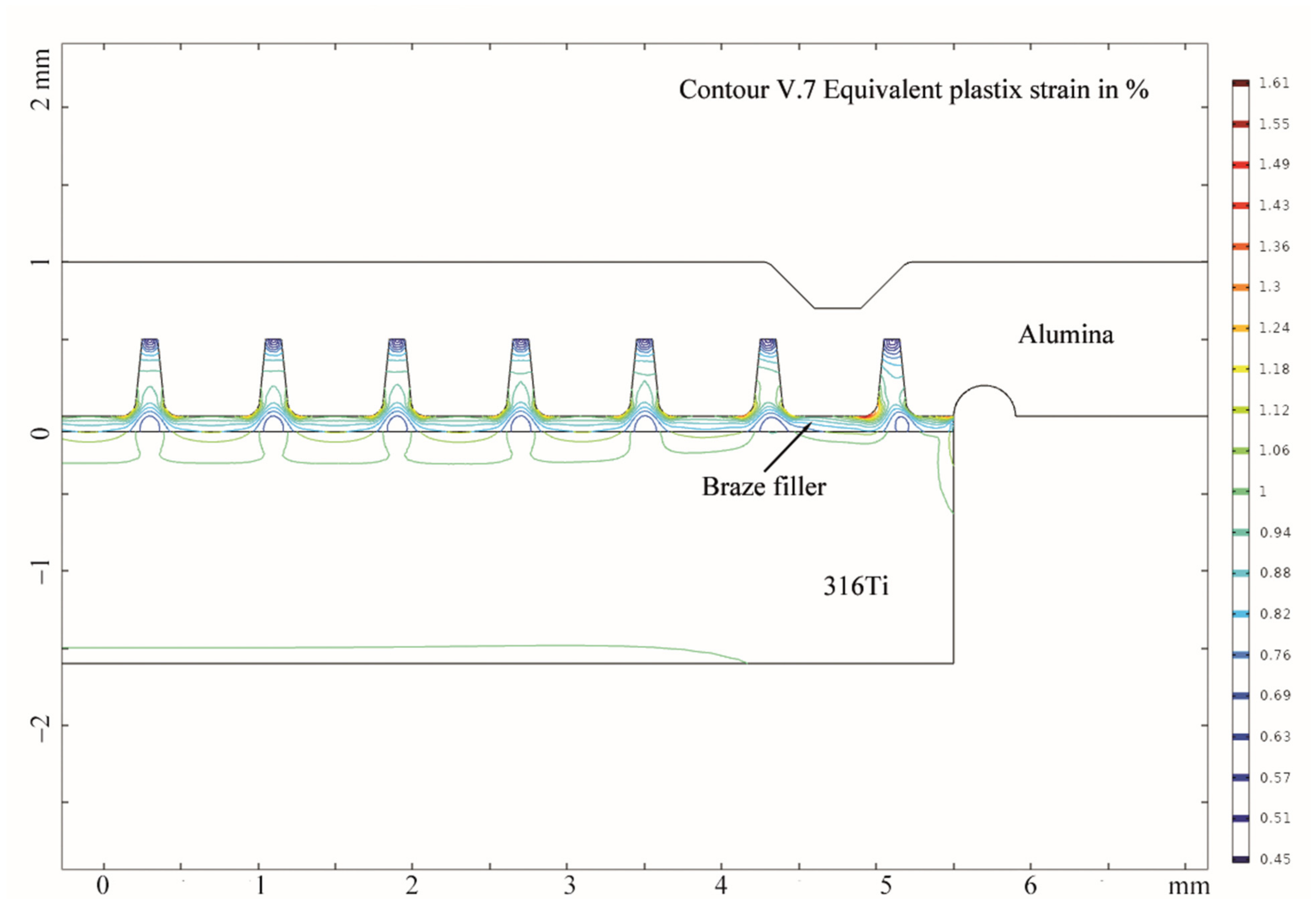
- Feng, J.; Herrmann, M.; Reinecke, A.-M.; Hurtado, A. Interface optimization for thermal residual stress reduction at laser-brazed ceramic-stainless steel joints for miniaturized energy sensors. In Proceedings of the EuroMat 2023, Frankfurt, Germany, 3–7 September 2023. [Google Scholar]
- Feng, J.; Herrmann, M.; Reinecke, A.-M.; Hurtado, A. Deterministic processing of alumina with nanosecond laser pulses for energy applications. In Proceedings of the EuroMat 2023, Frankfurt, Germany, 3–7 September 2023. [Google Scholar]
- Reyes, J.N.; Groome, J.T.; Woods, B.G.; Jackson, B.; Marshall, T.D. Scaling analysis for the high temperature Gas Reactor Test Section (GRTS). Nucl. Eng. Des. 2010, 240, 397–404. [Google Scholar] [CrossRef]
- Aoto, K.; Dufour, P.; Hongyi, Y.; Glatz, J.P.; Kim, Y.; Ashurko, Y.; Hill, R.; Uto, N. A summary of sodium-cooled fast reactor development. Prog. Nucl. Energy 2014, 77, 247–265. [Google Scholar] [CrossRef]
- Lin, C.C. A review of corrosion product transport and radiation field buildup in boiling water reactors. Prog. Nucl. Energy 2009, 51, 207–224. [Google Scholar] [CrossRef]
- Sandlin, S.; Kosonen, T.; Hokkanen, A.; Heikinheimo, L. Use of brazing technique for manufacturing of high temperature fibre optical temperature and displacement transducer. Mater. Sci. Technol. 2007, 23, 1249–1255. [Google Scholar] [CrossRef]
- Schilm, J.; Goldberg, A.; Partsch, U.; Dürfeld, W.; Arndt, D.; Pönicke, A.; Michaelis, A. Joining technologies for a temperature-stable integration of a LTCC-based pressure sensor. J. Sens. Sens. Syst. 2016, 5, 73–83. [Google Scholar] [CrossRef]
- Okamoto, N.; Miura, K.; Kondo, K.; Asano, T.; Banno, H. Brazing technology for low temperature cofired ceramics and its application to MCM. In Proceedings of the 1995 Japan International Electronic Manufacturing Technology Symposium, Omiya, Japan, 4–6 December 1995; pp. 40–43. [Google Scholar]
- Monti, R.; Coppola, F.; Gasbarri, P.; Lecci, U. Residual stress brazing process induced in hybrid package for ISP applications. Acta Astronaut. 2010, 66, 897–913. [Google Scholar] [CrossRef]
- Walker, C.A.; Uribe, F.; Monroe, S.L.; Stephens, J.J.; Goeke, R.S.; Hodges, V.C. High-temperature joining of low temperature cofired ceramics. In Proceedings of the 3rd International Brazing and Soldering Conference, San Antonio, TX, USA, 24–26 April 2006; pp. 54–59. [Google Scholar]
- Ni, M.; Leung, M.K.H.; Leung, D.Y.C. Technological development of hydrogen production by solid oxide electrolyzer cell (SOEC). Int. J. Hydrog. Energy 2008, 33, 2337–2354. [Google Scholar] [CrossRef]
- Weil, K.S.; Coyle, C.A.; Hardy, J.S.; Kim, J.Y.; Xia, G.G. Alternative planar SOFC sealing concepts. Fuel Cells Bull. 2004, 2004, 11–16. [Google Scholar] [CrossRef]
- Kim, J.Y.; Hardy, J.S.; Weil, K.S. Silver-copper oxide based reactive air braze for joining yttria-stabilized zirconia. J. Mater. Res. 2005, 20, 636–643. [Google Scholar] [CrossRef]
- Sun, Y.S.; Driscoll, J.C. A new hybrid power technique utilizing a direct Copper to ceramic bond. IEEE Trans. Electron Devices 1976, 23, 961–967. [Google Scholar] [CrossRef]
- Luo, Y.; Song, X.G.; Hu, S.P.; Xu, Z.Q.; Li, Z.H.; Lei, Y. Reactive air brazing of Al2O3 ceramic with Ag-CuO-Pt composite fillers: Microstructure and joint properties. J. Eur. Ceram. Soc. 2021, 41, 1407–1414. [Google Scholar] [CrossRef]
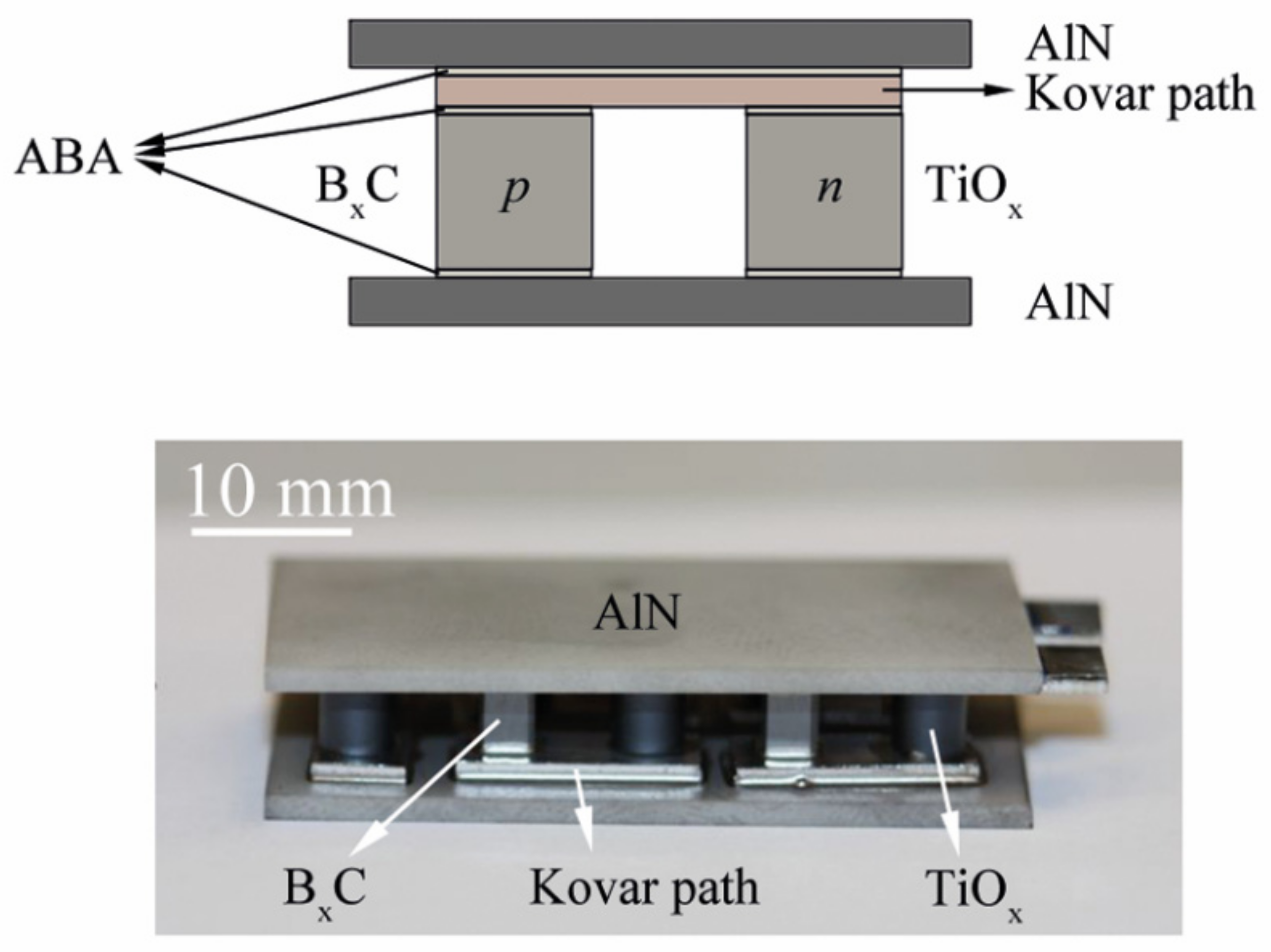
- Conze, S.; Poenicke, A.; Martin, H.P.; Rost, A.; Kinski, I.; Schilm, J.; Michaelis, A. Manufacturing Processes for TiOx-Based Thermoelectric Modules: From Suboxide Synthesis to Module Testing. J. Electron. Mater. 2014, 43, 3765–3771. [Google Scholar] [CrossRef]
- Martin, H.P.; Pönicke, A.; Kluge, M.; Sichert, I.; Rost, A.; Conze, S.; Wätzig, K.; Schilm, J.; Michaelis, A. TiOx-Based Thermoelectric Modules: Manufacturing, Properties, and Operational Behavior. J. Electron. Mater. 2016, 45, 1570–1575. [Google Scholar] [CrossRef]
- Börner, F.D.; Schreier, M.; Feng, B.; Lippmann, W.; Martin, H.P.; Michaelis, A.; Hurtado, A. Development of laser-based joining technology for the fabrication of ceramic thermoelectric modules. J. Mater. Res. 2014, 29, 1771–1780. [Google Scholar] [CrossRef]
- Feng, B.; Martin, H.-P.; Börner, F.-D.; Lippmann, W.; Schreier, M.; Vogel, K.; Lenk, A.; Veremchuk, I.; Dannowski, M.; Richter, C.; et al. Manufacture and Testing of Thermoelectric Modules Consisting of BxC and TiOx Elements. Adv. Eng. Mater. 2014, 16, 1252–1263. [Google Scholar] [CrossRef]
- Mukerjee, S.; Leah, R.; Selby, M.; Stevenson, G.; Brandon, N.P. Chapter 9—Life and Reliability of Solid Oxide Fuel Cell-Based Products: A Review. In Solid Oxide Fuel Cell Lifetime and Reliability; Brandon, N.P., Ruiz-Trejo, E., Boldrin, P., Eds.; Academic Press: Cambridge, MA, USA, 2017; pp. 173–191. [Google Scholar]
- Woirgard, E.; Arabi, F.; Sabbah, W.; Martineau, D.; Theolier, L.; Azzopardi, S. Identification and analysis of power substrates degradations subjected to severe aging tests. Microelectron. Reliab. 2015, 55, 1961–1965. [Google Scholar] [CrossRef]
- Kiebach, W.R.; Knibbe, R.; Frederiksen, K.B.; Chen, M.; Mikkelsen, L.; Hendriksen, P.V. Investigation of Failure Mechanisms in Ti Containing Brazing Alloys Used in SOFC/SOEC Environments. In Proceedings of the ASME 2010 8th International Conference on Fuel Cell Science, Engineering and Technology, Brooklyn, NY, USA, 14–16 June 2010; pp. 655–665. [Google Scholar]
- Qiao, G.J.; Zhang, C.G.; Jin, Z.H. Thermal cyclic test of alumina/kovar joint brazed by Ni–Ti active filler. Ceram. Int. 2003, 29, 7–11. [Google Scholar] [CrossRef]
- Dandapat, N.; Ghosh, S.; Pal, K.S.; Datta, S.; Guha, B.K. Thermal cycling behavior of alumina-graphite brazed joints in electron tube applications. Trans. Nonferrous Met. Soc. China 2014, 24, 1666–1673. [Google Scholar] [CrossRef]


Disclaimer/Publisher’s Note: The statements, opinions and data contained in all publications are solely those of the individual author(s) and contributor(s) and not of MDPI and/or the editor(s). MDPI and/or the editor(s) disclaim responsibility for any injury to people or property resulting from any ideas, methods, instructions or products referred to in the content. |
© 2024 by the authors. Licensee MDPI, Basel, Switzerland. This article is an open access article distributed under the terms and conditions of the Creative Commons Attribution (CC BY) license (https://creativecommons.org/licenses/by/4.0/).
Share and Cite
Feng, J.; Herrmann, M.; Reinecke, A.-M.; Hurtado, A. Active Brazing for Energy Devices Sealing. J. Exp. Theor. Anal. 2024, 2, 1-27. https://doi.org/10.3390/jeta2010001
Feng J, Herrmann M, Reinecke A-M, Hurtado A. Active Brazing for Energy Devices Sealing. Journal of Experimental and Theoretical Analyses. 2024; 2(1):1-27. https://doi.org/10.3390/jeta2010001
Chicago/Turabian StyleFeng, Jian, Marion Herrmann, Anne-Maria Reinecke, and Antonio Hurtado. 2024. "Active Brazing for Energy Devices Sealing" Journal of Experimental and Theoretical Analyses 2, no. 1: 1-27. https://doi.org/10.3390/jeta2010001