1. Introduction
Diminished reality (DR) is a technology that creates the illusion of objects being removed from real space. In contrast to augmented reality (AR), which overlays virtual objects onto real objects to make them appear as if they exist in real space, DR displays a background image over the real object to make it appear as if the object has been removed.
DR is expected to have various applications, such as removing the current scene to recreate a past or future scene and removing obstacles like walls and car bodies to enable safety confirmation from previously impossible viewpoints [
1,
2].
Moreover, by removing such obstacles, DR has the potential to address a challenge in AR where virtual objects cannot be placed due to real-world obstacles. For this purpose, our research aimed to realize a DR application that displays a scene without a target object in the image in real time using the camera of a smartphone. The real-time DR application is also expected to have various uses, such as assisting in interior simulation and live streaming.
Focusing on the method of obtaining the background to hide the target object, DR methods can be classified into two types: observation-type methods that observe the real background and completion-type methods that estimate the background from the region around the target object [
1]. The observation-type method is a DR method that has been used for a long time. This method obtains real background images from multiple viewpoints and past images and uses these images to perform DR. On the other hand, the completion-type method performs DR by guessing scenes in which the object does not exist. In many cases of this method, the object is filled in once and a scene is created in which the object is not present by guessing the background image of the filled-in region. The completion-type method performs DR by removing the object from the scene as a result of completing a filled-in region in the scene.
An example of an observation-type method is the removal of obstructive objects, such as pipes, in a video stream [
3]. Another example is using the difference in viewpoints between a surveillance camera and a camera on a mobile device to enable a perspective view of a building [
4]. Furthermore, a study of a system to reduce car accidents has been reported [
5]. This system transmits camera information from the car in front to the car behind it and removes the car in front from the scene that is viewed from the car behind. In addition, an example has been reported that realizes fast and accurate DR using a 3D model for DR created by observing the background and surrounding environment without the target objects in advance [
6]. Observation-type methods have many requirements, such as advanced preparation and special equipment. Also, they cannot cope with cases where the real background is unobservable. Therefore, this method cannot perform DR in real time. For this reason, observation-type methods are not suitable for DR applications, which are the focus of this research.
Studies using both observation-type and completion-type methods have also been reported [
7,
8,
9]. In these studies, the observation-type method used builds a 3D model of a landscape without objects that need to be removed by moving the camera. The traditional completion-type method used compensates for unobservable regions using PixMix [
10] or other methods that enable inpainting by filling in the regions with patches and pixels from the rest of the image. The observation-type method still has the disadvantage of performing incomplete DR until the construction of the 3D model is completed. Therefore, methods that only use the observation-type method are not suitable for our DR application. A method that combines image processing with the real background information observed in previous frames has also been reported [
11]. However, the contribution of this method, in which real background information is combined with the inpainting results through image processing, requires observation of the hidden area by changing the camera’s position and angle. Also, this method requires an RGB-D camera, unlike our application, which is realized using a smartphone camera. This is because the inpainting results and real background information are created as a 3D model.
The completion-type method guesses the background to be used for DR from the surrounding background information. Therefore, it does not require advance preparation, unlike the observation-type method, and it can be used for areas that cannot be observed by the camera. For these reasons, only the completion-type method was used for our DR application.
Examples of DR using the completion-type method include object removal in panoramic images [
12], the removal of unwanted people and objects in photographs [
13,
14], and the removal of AR markers [
15,
16,
17]. A study of object removal from panoramic images [
12] aimed to remove furniture from a spherical panorama of an indoor scene. The method used in this study fills in the objects in the image once with white. Then, it uses a deep learning network to restore the filled-in area to a scene without objects in it, matching it to the surrounding background. The function of removing unwanted people and objects in a photo [
13,
14] is actually implemented in image editing applications as removing tools. They can remove objects from an image by specifying the objects to be removed. In the examples [
15,
16,
17], AR markers are removed by applying traditional completion-type methods, such as generating backgrounds by calculating information from the surrounding background, and using backgrounds with similar patterns clipped from previous frames.
These completion-type methods using machine learning are more accurate than traditional completion-type methods [
15,
16,
17] in terms of the background image used for DR and can be used for complex backgrounds. However, most of them are used for still images that have already been captured [
12,
13,
14]. Therefore, there is no guarantee that they are suitable for real-time processing, and it is difficult to use these machine learning models under the conditions that were used in the examples for our DR application. Accordingly, in this study, the machine learning model used for the DR application was also examined in order to achieve real-time processing.
There are very few examples of real-time DR using machine learning. A study using real-time DR for buildings has been reported [
18]. This involves recognizing buildings from images of landscapes that include buildings and performing DR in the region that contains the buildings. This method recognizes and removes all architectural objects in a landscape image using semantic segmentation and does not remove arbitrary objects that are specified. It also requires the recognition of a 2D region for DR at each frame. DeepDR, an image inpainting network for DR, has also been reported [
19]. In addition to the RGB images, the depth information is also required as an input for this network. Therefore, this network is not suitable for our application, which is realized using a smartphone camera, because a DR system using this network requires an RGB-D camera.
In the field of mixed reality (MR), which merges the virtual world with the real world, a study using DR based on machine learning has also been reported [
20]. In this study, cars and people were removed in real space, and virtual objects were displayed in their place. However, the types of objects to be removed were limited. In addition, since client servers are used for DR and AR processing, an Internet environment is essential.
In this study, the deletion target is specified by a 3D region. By specifying a completion region that contains the object to be removed instead of the target, the process of detecting the target to be removed can be omitted, and DR for targets with various shapes and sizes can be realized. In addition, it is possible to keep the scene without the specified object even if the viewpoint position or angle changes. Moreover, 3D regions can be specified without relying on background information. A series of application processes can be executed on a laptop connected to a smartphone, eliminating the need for a network environment.
A study evaluating DR for 3D regions has already been reported [
21]. However, the method used for DR is based on a patch search, which can only be used on backgrounds with a regular pattern, making it difficult to use in general environments. The background of the frame specifying the 3D region must be planar in order to project the 3D region from the camera position onto the estimated background plane.
A deep learning network is used for the completion function. To determine which network to use, we compared multiple networks experimentally and selected the network that could provide fast and accurate completion. In addition, by improving the loss function during training, the completion accuracy was significantly improved compared to previous methods.
Our DR application does not require an RGB-D camera. The DR application was run on a smartphone and a laptop computer, and operation at 10 fps was confirmed. We believe that a real-time DR system that can be realized using only a non-top-tier laptop computer and a smartphone can have a variety of applications.
4. Experiment
4.1. Training
A dataset was created using indoor images [
26,
27,
28,
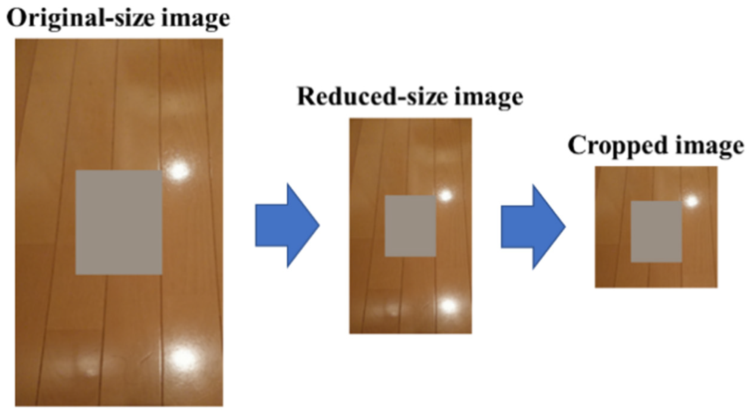
29]. The image size of the dataset was determined as 128 × 128 pixels. Since the collected indoor images were larger than 128 × 128 pixels and were not square, they were first downscaled to 256 pixels on the short side. Then, multiple 128 × 128-pixel images were cropped from the downscaled images to create the dataset. Additionally, left–right inverted images of the cropped images were included in the dataset. A total of 16,094 images were used for training, while 1884 images were used for evaluation. The original indoor images were divided into separate sets for each purpose to ensure that the training and evaluation sets were distinct.
One simple method to train a completion network for DR involves extracting the contour of an object, creating a filled-in image using a single color within the contour, and training it to complete the filled-in region. However, this method has the following disadvantages:
It requires a dataset of combinations of images with the target object to be removed and the same image without the object. Therefore, it is difficult to increase the number of variations in the dataset.
The surrounding pixel values are altered by the light reflected by the object and shadows of the object. As a result, the pixel values of the generated completion images change from the background image without a target object. Therefore, it is difficult to evaluate the completion images accurately.
It is difficult to evaluate completion images where objects in various positions and of various sizes are removed.
To solve the above problems, this study treated the training data images as background images after DR. Then, an object was assumed to be placed on this background image, and a completion region was created to include the object. In this way, an image with a completion region was combined with a background image that was the correct image.
The network is trained to recover the original background from the completion region image. The size of the completion region was determined as w × h (pixels), where w and h were randomly determined to be in the range of 16 to 64.
Figure 10 shows examples of the original images (correct answers) and the images with completion regions (input images).
This approach has the following advantages:
This method can easily increase the number of variations in the dataset rather than having combinations of images with the target object to be removed and the same image without the object.
The effect of the object’s placement on the surrounding pixel values can be suppressed. Therefore, the evaluation of the completion images can also be performed accurately.
Completion images with various positions and various sizes of target objects can be evaluated.
The data with variations may have a positive impact on the training of the network.
In addition, network training was conducted in three phases. The first phase involved training only the completion network. Then, in the second phase, the weights of the completion network were fixed, and only the discriminators were trained. Finally, in the third phase, the completion network and the discriminator were trained in parallel, as if they were competing against each other. The loss function and optimization method were the same as in GLCIC [
23]. The input for the local discriminator was a 64 × 64-pixel image centered on the completion region of the 128 × 128-pixel completion images [
23].
4.2. Evaluation Method
The accuracies of the completion regions of the generated completion images were evaluated using the evaluation images. Since the accuracies of the completion regions depend on the sizes of the completion regions, the accuracies were evaluated for seven different sizes of completion regions (16 × 16, 24 × 24, …, 56 × 56, 64 × 64). The completion accuracies were calculated by averaging the completion accuracies of the 1884 evaluation images for each size of completion region. Furthermore, the average completion accuracy was evaluated for completion regions of various aspect ratios and sizes (VARAS). The completion regions of VARAS were determined randomly in the range of 16 to 64 in length and width. The evaluation indices used were PSNR (peak signal-to-noise ratio), SSIM (structural similarity), and LPIPS (learned perceptual image patch similarity). PSNR and SSIM only evaluate the completion regions, while LPIPS evaluates the entire images. Here, the completion regions of the original images are completed by the output images of the network because the evaluation of perceptual similarity should include not only the completion regions, but also the relationships with the surroundings of the completion regions. The speed of generating the completion images was also measured and compared.
4.3. Comparison of Completion Networks
Figure 11,
Figure 12 and
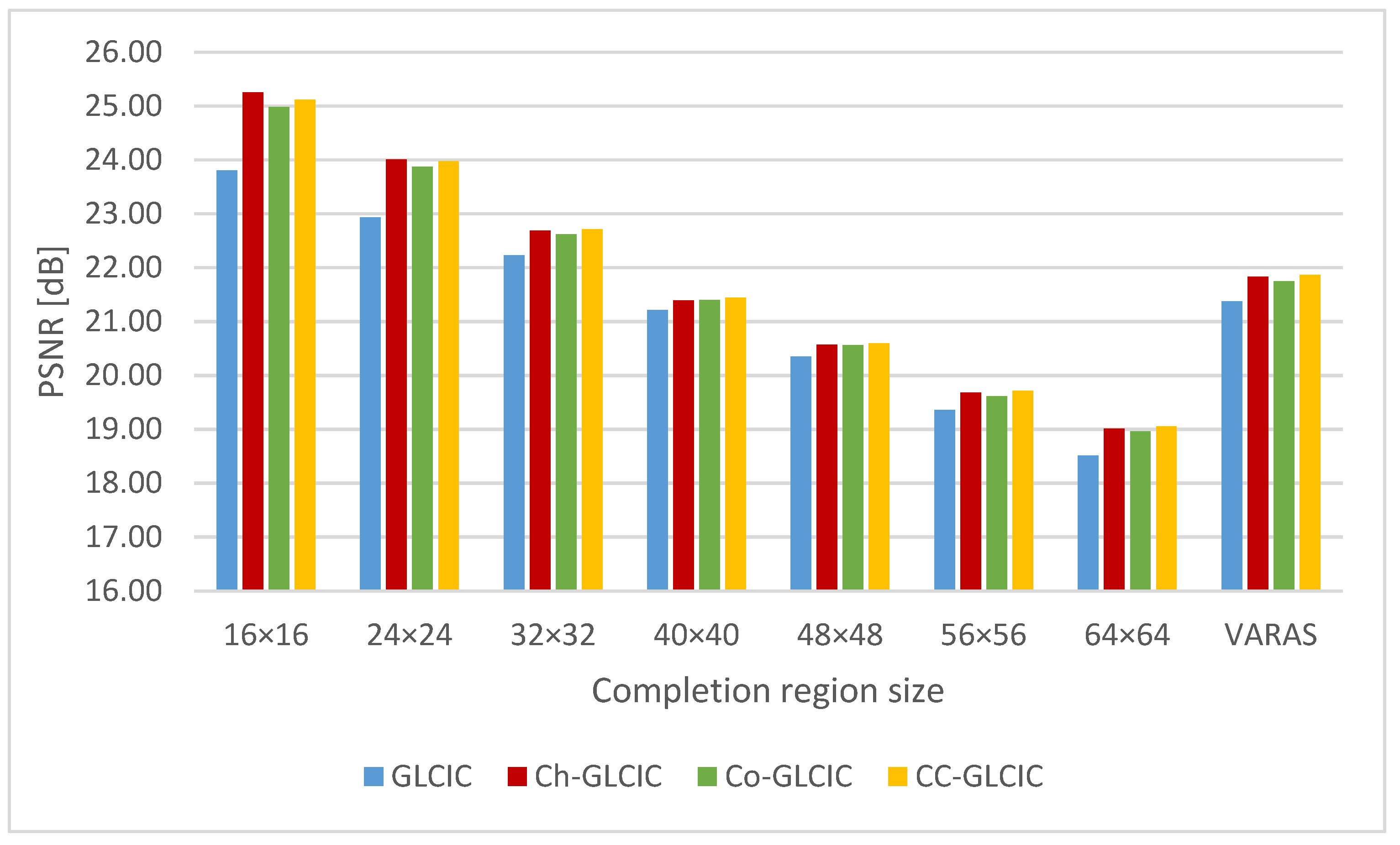
Figure 13 show the completion accuracies of each network for each size of completion region and the completion regions of VARAS. Larger values for PSNR and SSIM represent better evaluations, while smaller values for LPIPS represent better evaluations. Ch-GLCIC, Co-GLCIC, and CC-GLCIC were more accurate than GLCIC in all completion region sizes for all measures. A comparison of Ch-GLCIC, Co-GLCIC, and CC-GLCIC shows that Ch-GLCIC and CC-GLCIC have higher completion accuracies than Co-GLCIC in all measures. In PSNR and SSIM, Ch-GLCIC showed the most improved completion accuracy compared to GLCIC at a 16 × 16-pixel completion region, with PSNR and SSIM being improved by more than 1 dB and 0.08. In LPIPS, Ch-GLCIC showed the most improved completion accuracy compared to GLCIC at a 64 × 64-pixel completion region, with LPIPS improving by approximately 0.024.
Figure 14 shows the sample completion results for each network. These images correspond to the average completion accuracy of Ch-GLCIC at each completion region size. It can be seen that Ch-GLCIC, Co-GLCIC, and CC-GLCIC produce images with fewer differences in terms of color and pattern than GLCIC.
The processing speed of generating the completion images was measured using a notebook PC (Mouse Computer Co., Ltd., Tokyo, Japan) with the following specifications:
OS: Windows10 Pro;
CPU: Core i7-8750H (2.2 Hz);
GPU: GeForce GTX1050 (2 GB).
Table 1 shows the results. Among the four networks, Ch-GLCIC and GLCIC exhibited the fastest generation speeds, which can be attributed to their smaller network sizes compared to Co-GLCIC and CC-GLCIC. The generation speeds of GLCIC and Ch-GLCIC were almost the same, which shows that channel attention does not have a great effect on the generation speed.
Overall, Ch-GLCIC is the only one of the four completion networks that has both a high completion accuracy and high processing speed when generating completion images. Therefore, Ch-GLCIC was chosen as the completion function for our DR application.
4.4. Improvement in Network Training
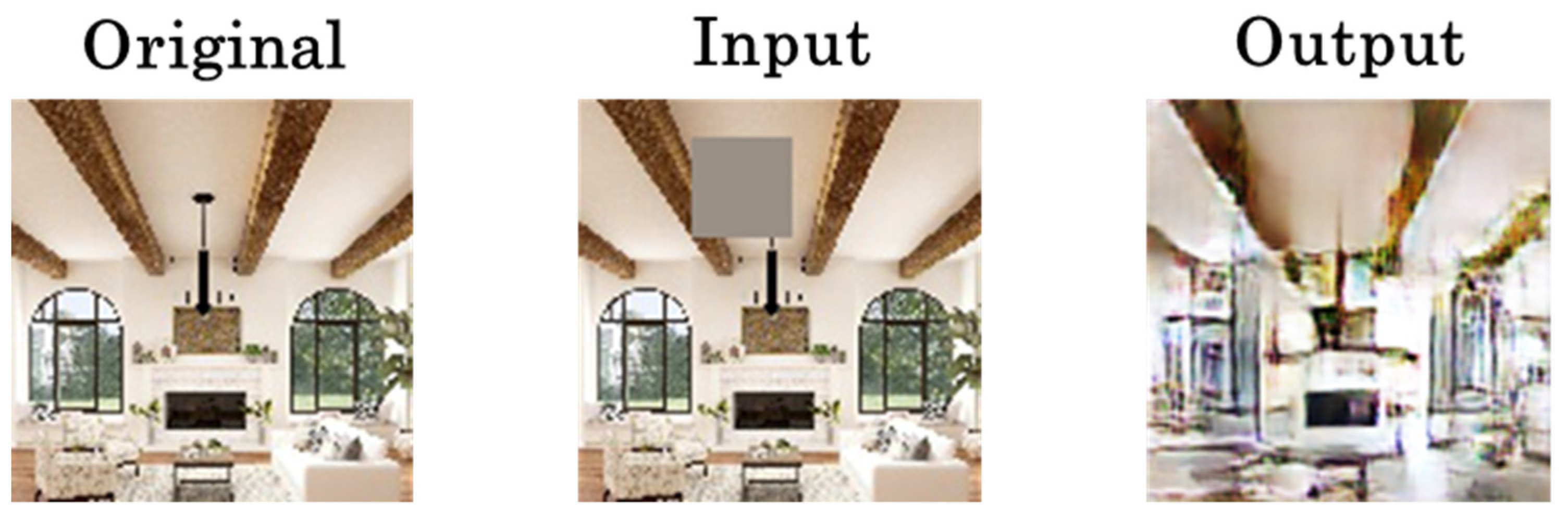
The completion images generated using the completion network are combined with the original image only in the completion region, and the other regions are not used. However, completion regions are completed by the surrounding information. Therefore, if the accuracies of the non-completion regions are low, the accuracies of the completion regions are also expected to be low. On the other hand, the completion network of GLCIC focuses only on the completion region and trains using only the MSE loss in the completion region [
23].
Figure 15 shows an example of the completion network’s output image. Since the MSE loss out of the completion region is not taken into account, the generated image out of the completion region is degraded compared to the original image.
Therefore, we attempted to improve this problem by adding the MSE loss from the completion region to the loss function of the completion network. The new loss function is shown in Equation (1).
In Equation (1), is the MSE loss within the completion region and is the MSE loss outside of the completion region. The training process outside of the completion region is faster than that within the completion region because of the information available in the input image. This may negatively impact training within the completion region due to overtraining outside of the completion region being carried out before training within the completion region reaches its maximum potential. To balance the learning rates inside and outside of the completion region, a weight β is applied outside of the completion region. A β value of 0 corresponds to the conventional loss function.
The completion accuracies were evaluated by varying the value of
β to determine its optimal value. The values of PSNR and SSIM for different values of
β are presented in
Figure 16, where they represent the average values obtained for seven different completion region sizes. As can be observed from
Figure 17, the network trained with the new loss function (
β > 0) performs better than the network trained with the conventional loss function (
β = 0). The highest completion accuracy was achieved when
β was set to 0.5.
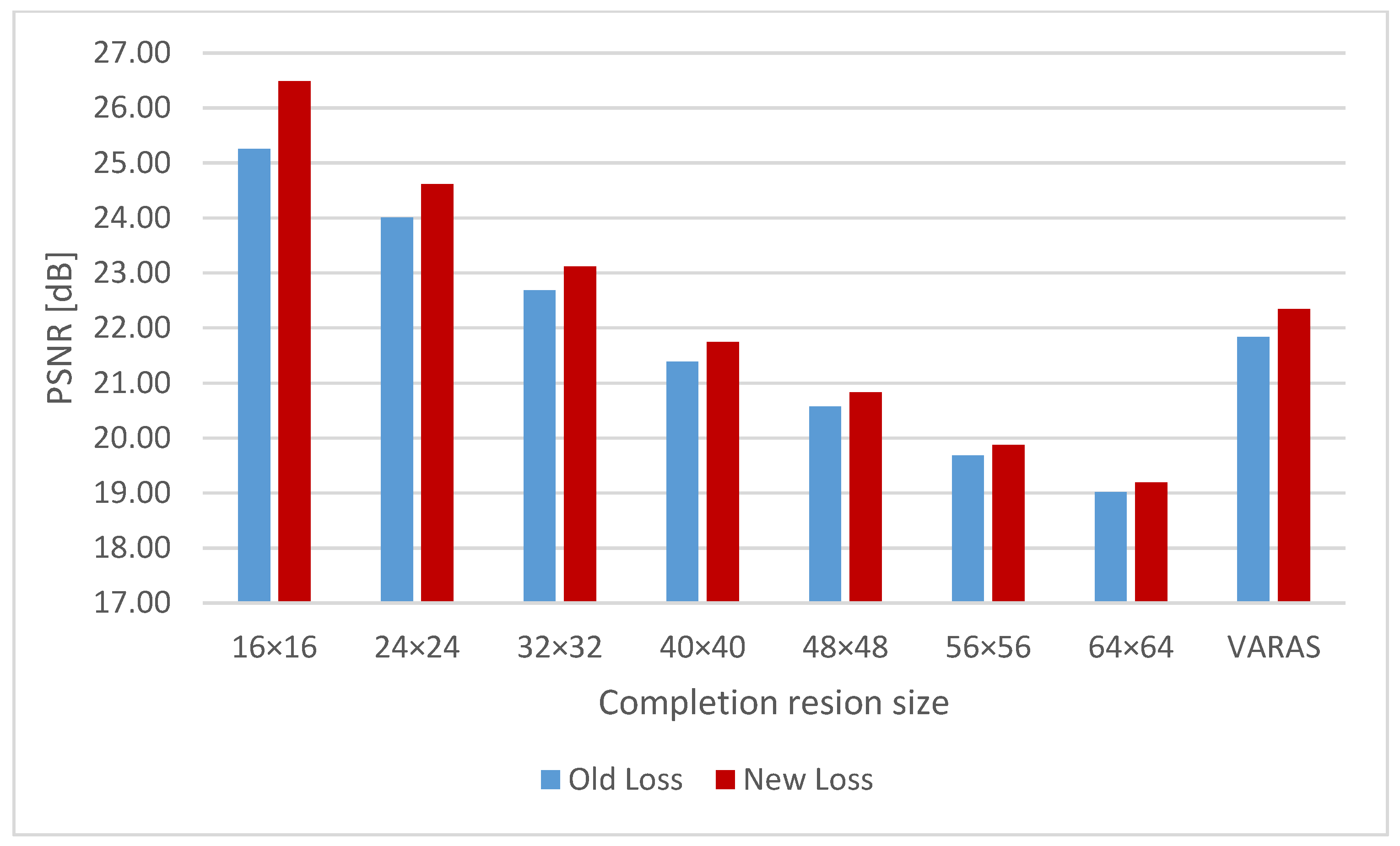
Figure 17,
Figure 18 and
Figure 19 show the completion accuracies of the conventional loss function and the new loss function (
β = 0.5) for seven different completion region sizes and completion regions of VARAS. For all three measures, the completion accuracy was improved by the new loss function. In PSNR and SSIM, the improvement in completion accuracy was most significant at the 16 × 16-pixel completion region, where PSNR and SSIM increased by approximately 1.2 dB and 0.03, respectively. In LPIPS, the largest improvement was seen at the 56 × 56-pixel completion region, with an improvement of approximately 0.004.
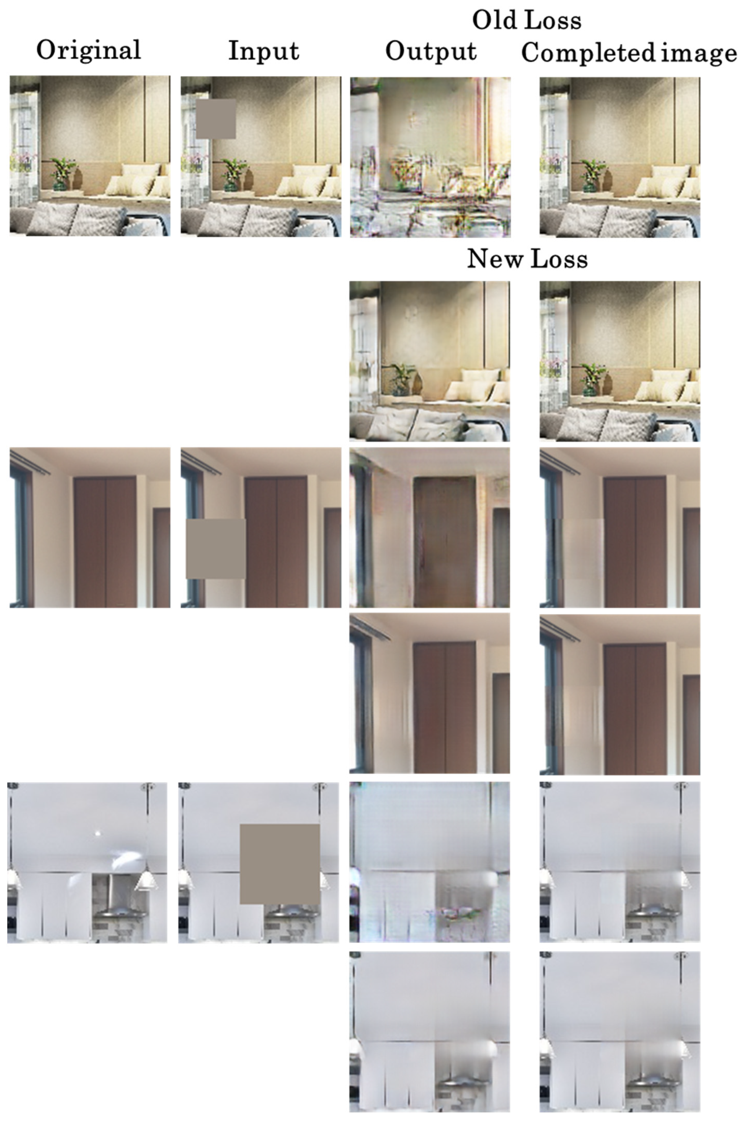
Figure 20 displays examples of completion results for networks trained with both loss functions. The completion images generated by the network using the new loss function have a clearer continuity of edges than the completion images generated by the network using the old loss function. This is because the network using the new loss function generates the entire images with high accuracy, and not only within the completion regions of the completion images. As a result, the final composite images become clearer.
4.5. Operational Experiments of the DR Application
Operational experiments were conducted for the DR application using Ch-GLCIC, which was trained with the improved loss function described in
Section 4.4. The experiments were conducted using a Google Pixel 4 smartphone (Google Inc., Mountain View, CA, USA) connected to a laptop computer via USB.
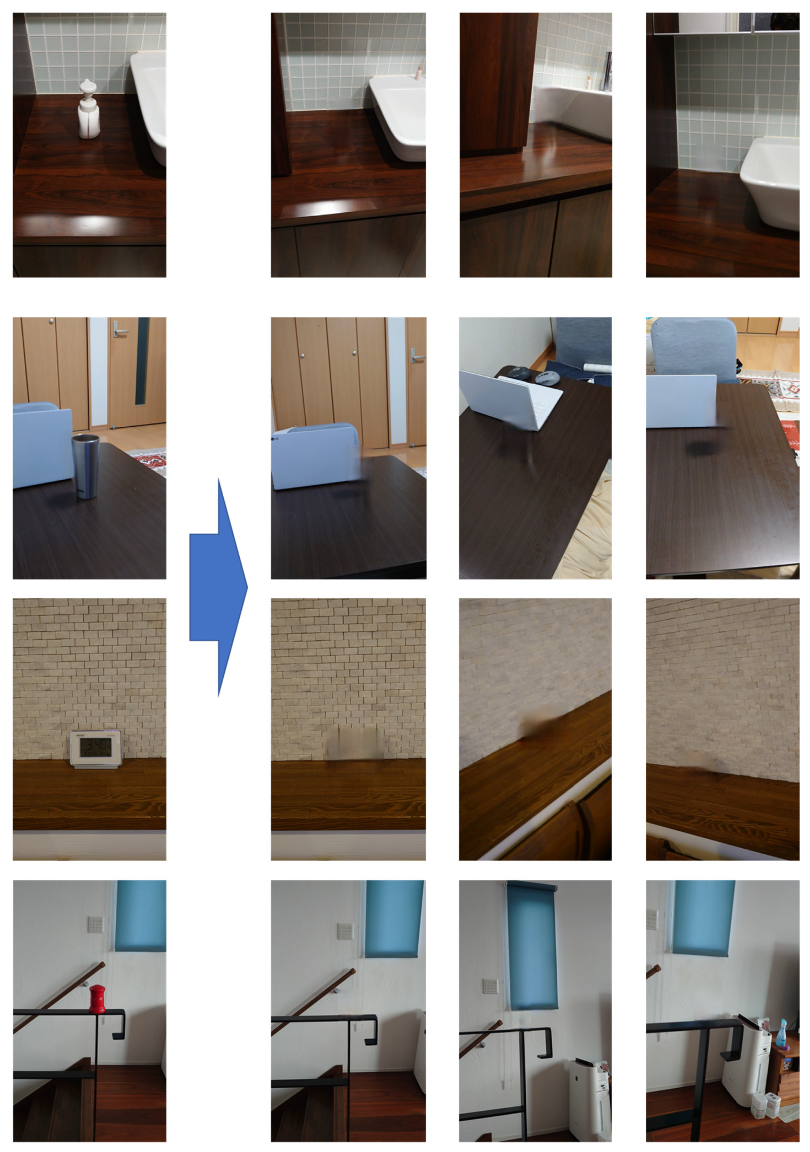
Figure 21 shows examples of the execution results of the DR application. All operational experiments were conducted in environments that were not used to train the network. The results show that by setting up the completion region as the 3D region, the real object can be removed even if the viewpoint changes. Furthermore, as shown in the bottom example in
Figure 21, the object located higher than the plane can be removed since a virtual cylinder can be placed higher than the virtual plane.
The processing speed of the DR application after manually setting the 3D regions (2.5 to 2.8) was 10 fps (please see the
Supplementary Materials Video S1 for more details). Therefore, we consider that the DR application achieved real-time DR.
5. Conclusions
We developed a real-time diminished reality (DR) application using a smartphone camera. The DR application is capable of removing objects inside a 3D region specified by the user in images captured using a smartphone camera. By specifying a 3D region that contains the target object to be removed instead of the target, the process for detecting the deletion target can be omitted, and DR for targets with various shapes and sizes can be realized. In addition, the specified target can be removed even if the viewpoint changes. To achieve fast and accurate DR completion, a suitable deep learning network was employed based on the results of the performance evaluation experiments. As a result, Ch-GLCIC, a network in which channel attention is incorporated into GLCIC, was employed for the DR application. Additionally, the loss function during the training process was improved to enhance the completion accuracy. In the operational experiments, the application was used in rooms that were not included in the training data, and it was found that DR was performed with little sense of discomfort. These results indicate that if the training data are sufficient, it might be possible to use DR applications in environments that are different from those used for the training data. The application can run in real time (10 [fps]) using a non-top-tier notebook PC.
Future research includes further improvements in completion accuracy and processing speed. To improve the completion accuracy, we are considering incorporating additional information into the network input and further refining the network architecture and training approach. Also, since this study prioritized the development of an application that can run in real time on a non-top-tier laptop computer, the completion function of the application did not use the methods for the temporal coherence of the DR results, such as using previous frames, which required additional processing time. However, temporal coherence is an important factor in DR. Therefore, we will consider incorporating a method for temporal coherence, which does not significantly affect the processing time, into our application in the future. The 3D region is specified by the user using the GUI, so the evaluation of the UI would also be suitable for a future study.


